

APP 16-22
User manual
Installation, Operation and
Maintenance Manual
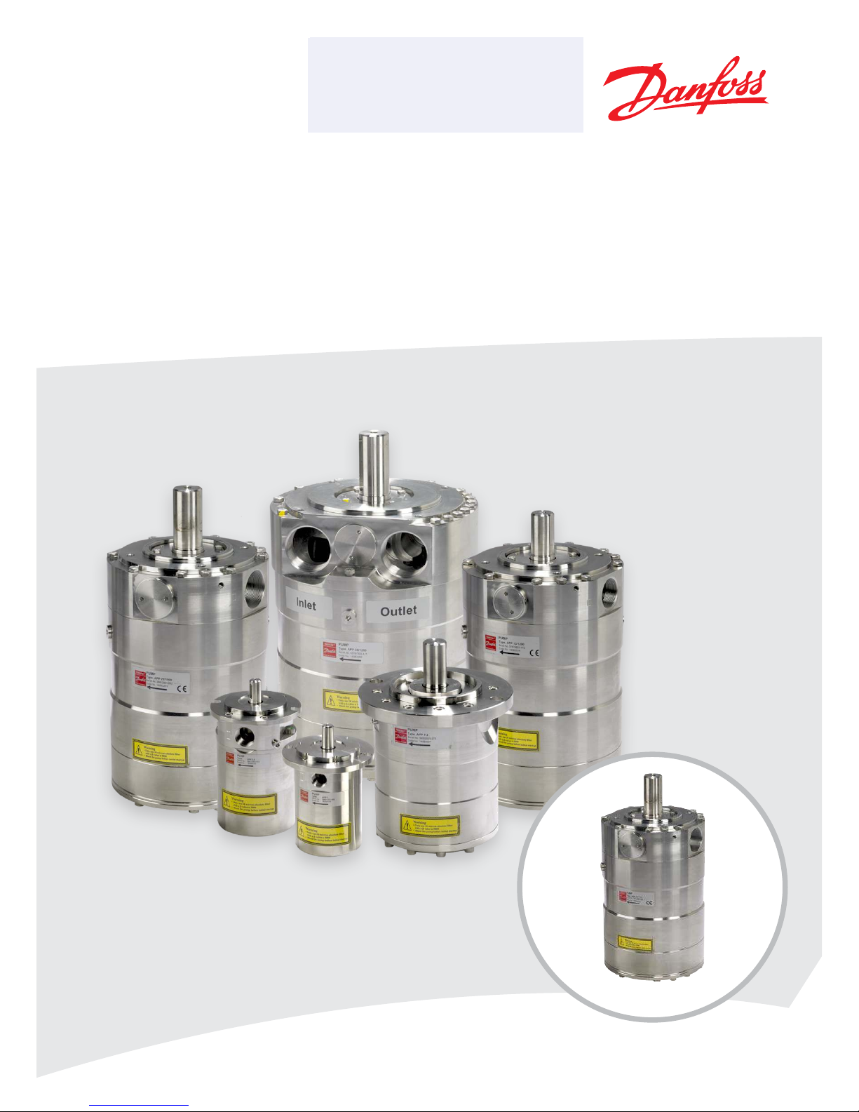
APP pumps (APP 16-22)
MAKING MODERN LIVING POSSIBLE
Lenntech
LQIR#OHQQWHFKFRP Tel. +31-152-610-900
ZZZOHQQWHFKFRP Fax. +31-152-616-289
LQIR#OHQQWHFKFRP Tel. +31-152-610-900
ZZZOHQQWHFKFRP Fax. +31-152-616-289
Lenntech

User manual Installation, Operation and Maintenance APP Pumps (APP 16-22)
2
180R9265 / IOM APP Pumps - v01 / 01.2013
Table of Contents Validity .........................................................................................4
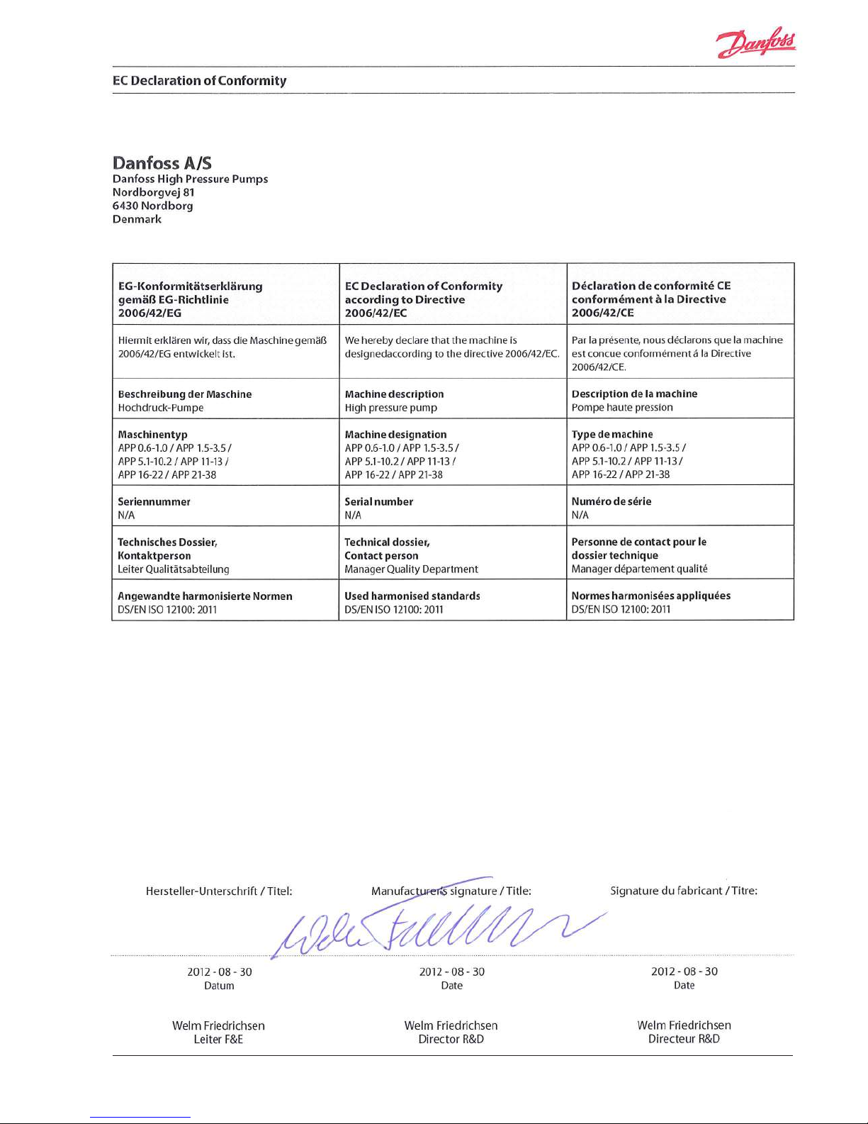
EC Declaration of Conformity
.......................................................................5
1. Introduction ............................................................................6
1.1 General.................................................................................6
1.2 Symbols ................................................................................6
1.3 Manufacturer and customer service address:............................................. 6
2. Safety ..................................................................................7
2.1 General information.....................................................................7
2.2 Preferred system design.................................................................7
2.3 Commissioning and servicing the unit ...................................................7
2.4 Adhere to the following important points ............................................... 7
2.5 In case of doubt .........................................................................7
3. Technical data ..........................................................................8
3.1 Approved applications and operational limits for the pumps .............................8
3.2 Application range .......................................................................8
3.3 Electric motor data...................................................................... 8
3.4 Noise and vibration .....................................................................8
3.5 General arrangement ................................................................... 8
3.6 Space requirement ......................................................................8
3.7 Filtration ................................................................................8
3.8 Properties of water ......................................................................8
3.9 Air bubbles .............................................................................8
3.10 Chemicals...............................................................................8
4. Arrival inspection, transportation, handling, lifting and storage .......................... 9
4.1 Arrival inspection .......................................................................9
4.2 Warning ................................................................................9
4.3 General safety information ..............................................................9
4.4 Transport and handling .................................................................9
4.5 Return to supplier ......................................................................10
4.6 Storage ................................................................................10
5. Installation and commissioning......................................................... 11
5.1 Important dimensions .................................................................11
5.2 Cleanliness............................................................................. 11
5.3 Fluid temperature......................................................................11
5.4 Electrical data.......................................................................... 11
5.5 Local regulations.......................................................................11
5.6 Pre mounting checklist, based on Danfoss preferred system design ..................... 12
5.7 Lifting and positioning .................................................................12
5.8 Mount the dierent equipment ........................................................12
5.9 Electrics ...............................................................................12
5.10 Instrumentation .......................................................................12
5.11 Connections ........................................................................... 12
5.12 Ensure free ow .......................................................................13
5.13 Verify setting of safety/relief valves .....................................................13
5.14 Flush the pump ........................................................................13
5.15 Bleed and remove air from the pump...................................................13
5.16 Verify direction of rotation .............................................................13
5.17 Commissioning ........................................................................13
5.18 Check the lter condition...............................................................13
5.19 Instruct operator and maintenance personnel .......................................... 13
6. Operation of motor pump unit .........................................................14
6.1 General safety information .............................................................14
6.2 What to listen and look for .............................................................14

User manual Installation, Operation and Maintenance APP Pumps (APP 16-22)
3
180R9265 / IOM APP Pumps - v01 / 01.2013
7. Maintenance and service of the pump unit .............................................15
7.1 General safety information .............................................................15
7.2 Service and inspection interval for the pump ...........................................15
7.3 Shut down of the system ...............................................................15
7.4 Disassembling and assembling the pump unit ..........................................15
7.5 Assembling the pump unit .............................................................16
7.6 Procedure for mounting pump back onto electric motor ................................16
7.7 Getting the pump unit back into operation .............................................16
7.8 Storage of the pump ...................................................................16
8. Troubleshooting and scrapping criteria .................................................17
8.1 General safety information .............................................................17
8.2 Operational conditions which can cause pump failures..................................17
8.3 Mechanical failure...................................................................... 17
8.4 Electrical failure........................................................................17
8.5 Responsibility ..........................................................................17
8.6 Scrapping criteria ......................................................................17
Subject index .....................................................................................18
User manual Installation, Operation and Maintenance APP Pumps (APP 16-22)
4
180R9265 / IOM APP Pumps - v01 / 01.2013
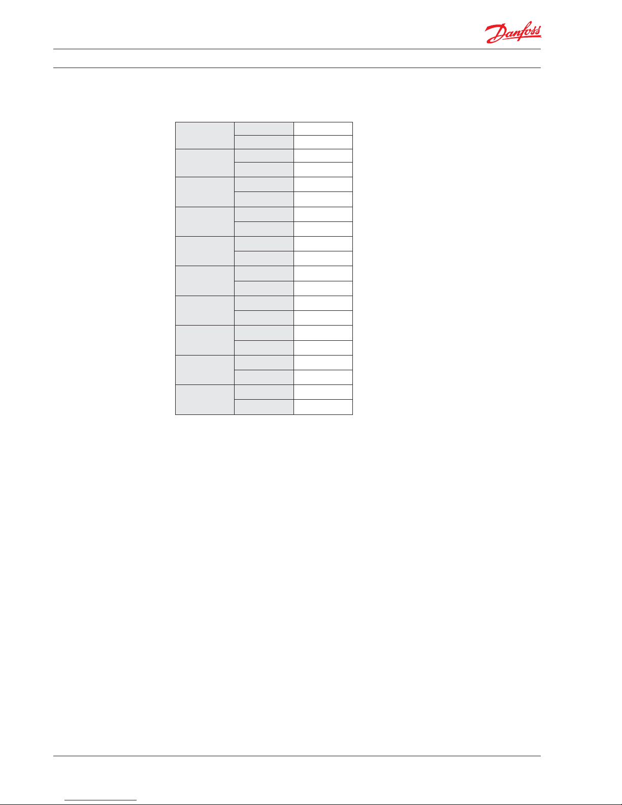
This manual is valid for APP pumps with the following code numbers/serial numbers:Validity
APP 16/1200 Code no. 180 B325 4
Serial no. 01
APP 16/1500 Code no. 180 B3250
Serial no. 01
APP 17/1200 Code no. 180 B3255
Serial no. 01
APP 17/1500 Code no. 180 B3251
Serial no. 01
APP 19/1200 Code no. 18 0B32 56
Serial no. 01
APP 19/1500 Code no. 180 B3252
Serial no. 01
APP 21/1200 Code no. 180B3051
Serial no. 05
APP 21/1500 Code no. 180B3052
Serial no. 03
APP 22/1200 Code no. 180 B3257
Serial no. 01
APP 22/1500 Code no. 180 B3253
Serial no. 01
5
180R9265 / IOM APP Pumps - v01 / 01.2013
EU Declaration of Conform-
ity
User manual Installation, Operation and Maintenance APP Pumps (APP 16-22)
6
180R9265 / IOM APP Pumps - v01 / 01.2013
1.1 General
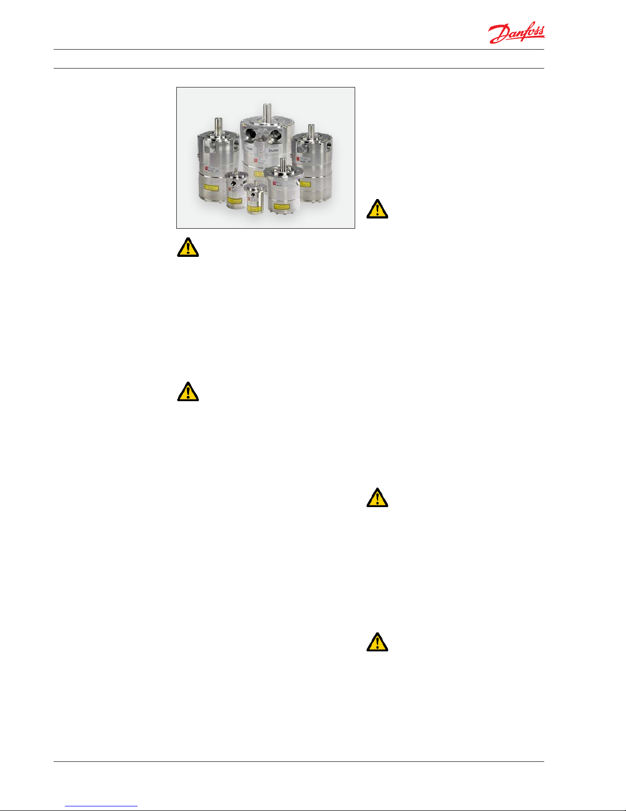
The APP pumps and pump units are manufactured by Danfoss A/S, and are sold and marketed
by a net of authorized distributors world wide.
This manual contains the necessary instructions
for the installation, operation and service of the
pumps used in a Sea Water Reverse Osmosis
(SWRO) or Brackish Water Reverse Osmosis
(BWRO) system.
The APP pumps must not be used for other
purposes than those recommended and
specied without rst consulting your local
pump distributor.
Use of the pump in other applications not
suitable for the pump unit can cause damages to
the pump unit, with risk of personal injury.
All personnel being responsible for operation
and maintenance of the pump unit must read
and fully understand these instructions,
especially the section “Safety” before:
tTransportation of the motor pump unit
tLifting the unit
tInstalling the pump unit
t
Connecting the motor pump unit to the
water system
t
Connecting the electric motor and instrumentation
tCommissioning the unit
t
Servicing the motor pump unit, mechanic
and electric parts
tDecommissioning the motor pump unit
The pump must always be installed and used in
accordance with existing national/local
sanitary, safety regulations and laws.
It is the responsibility of the safety ocer or
the chief operator to assure compliance with all
local regulations that are not taken into
account in this manual.
Changing the pumps’ or motor pump units’
operational limits and hardware:
t
Changes to the delivered pump or motor
pump system may only be done with a
written approval from Danfoss RO Solutions.
t Operation outside the Danfoss specications
requires a written approval from Danfoss RO
Solutions.
t If any changes are made without written
approval the warranty will automatically
become void.
Ensure that these instructions are always
readily available to all personnel concerned.
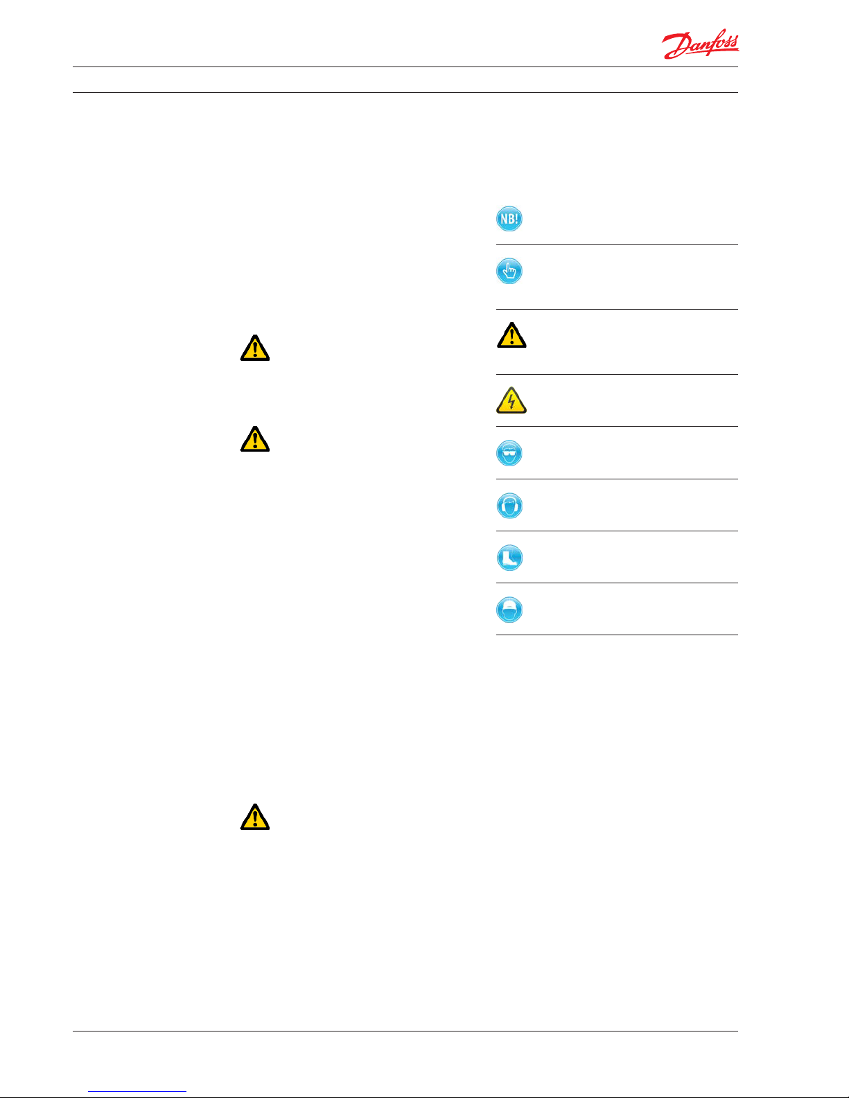
1.2 Symbols
Indicates something to be noted by the
reader
Indicates a situation which will or could
result in damage to the pump and its
function
Indicates a situation which will or could
result in personal injury and/or damage
to the pump
Electrical hazard - Indicates a high-
voltage warning
Safety glasses required
Hearing protection required
Safety shoes required
Safety helmet required
1.3 Manufacturer and customer service
address:
Danfoss A/S
RO Solutions
Nordborgvej 81, D25
DK-6430 Nordborg
Denmark
Tel ep hon e: +45 7488 4024
Fax: +45 7445 3831
Email: ro-solutions@danfoss.com
Homepage: www.ro-solutions.com
Your local Danfoss pump distributor can be
found on our homepage.
Data sheets and instructions on all accessories
are available on www.ro-solutions.danfoss.com
CE Declaration of Conformity can be found on
page 5.
1. Introduction
User manual Installation, Operation and Maintenance APP Pumps (APP 16-22)
7
180R9265 / IOM APP Pumps - v01 / 01.2013
2.1 General information
Dangers that can arise from not following the
instructions:
When the pump or pump system is managed by
untrained personal, there is a danger of:
tDeath or fatal injuries
tCostly damages and claims
Electrical
hazard
All electrical installation work must only be
carried out by authorized personnel in
accordance with EN60204-1 and/or local
regulations.
Install a lockable circuit breaker to avoid
inadvertent starting.
Protect the motor and other electrical equipment from overloads with suitable equipment.
!
Protective
garments
must be wor n
It is recommended to place a local safety switch
near by the pump, enabling service personal to
cut power for the electric motor. This prevents
unintentionally starting the unit during servicing.
Always wear suitable safety clothing when
handling the pump.
When working near the pump system, safety
proof boot/shoes, safety glasses, ear protection
and safety helmet must always be worn.
Under certain operational conditions the surface
of the pump can be above 60°C / 140°F.
Under these conditions the pump must be
labelled with a “Danger Hot” sign.
When using an electric motor, the motor must
always be supplied with adequate cooling
ventilation.
When using an electric motor together with a
VFD, the motor must be designed for operation
with VFD. VFD operation may increase the
temperature inside the electric motor if the
motor is not designed for VFD operation.
Before start-up, the settings for all protective
devices, for example, sensors/switches and
safety valves must be veried and free ow from
safety valves must be ensured.
All pipe and hose connections must be stressfree mounted, securely fastened to the pumps
and well supported. Improper installation will or
could result in personal injury and/or damage to
the pump.
Use of this manual does not relieve operation
and maintenance personnel of the responsibility of applying normal good judgment in the
operation and care of the pump and its
components.
2.2 Preferred system design
Danfoss recommends building systems with a
high degree of safety. See Danfoss preferred
system design and PI&D in Data sheet and
Instruction which are found in appendix 1 (Data
sheet) and 2 (APP pump instruction).
It is always the system builders responsibility that
the system design does not cause any kind of
hazard and is adapted to local regulations and
standards.
Proper installation, care of start up and shutdown devices and over-pressure protection
equipment is essential.
2.3 Commissioning and servicing the unit
It is recommended that commissioning and
servicing are carried out by a minimum of two
people, where one is acting as a supervisor.
2.4 Adhere to the following important
points
t
Before using the pump/pump unit it is very
important to read and understand this user
manual.
t Do not try to lift the pump unit manually;
most of the pumps weight more than
20 kilos, see specic weight for the pump
in the Data sheet, which is found in
appendix 1.
t Do not run the pump if it is completely dry
and not bleeded.
t Do not mount the pump without the bell
housing and a exible coupling.
t Do not try to start the unit before the
system components are mounted, bleeded
and adjusted.
2.5 In case of doubt
Please contact Danfoss A/S in case of doubt.
Contact information are listed in section 1.3,
Manufacturer and customer service address.
2. Safety
User manual Installation, Operation and Maintenance APP Pumps (APP 16-22)
8
180R9265 / IOM APP Pumps - v01 / 01.2013
3.1 Approved applications and operational
limits for the pumps
The pump and the pump units are designed for
the use in a Sea Water Reverse Osmosis (SWRO)
or Brackish Water Reverse Osmosis (BWRO)
systems.
The APP pumps must not be used for other
purposes than those recommended and
specied without rst consulting your local
pump distributor.
Use of the pump in other applications not
suitable for the pump unit can cause damages
to the pump unit, with risk of personal injury.
For system integration of the pumps, please
see Data sheet and Instruction which are found
in appendix 1 (Data sheet) and 2 (APP pump
instruction).
3.2 Application range
See Data sheet in appendix 1.
3.3 Electric motor data
See recommended motor in Data sheet,
appendix 1 or IOM for motors, appendix 3. The
motors mentioned are the most common used
motors by Danfoss High Pressure Pumps.
3.4 Noise and vibration
Noise level for a motor pump unit with a
”standard” motor measured according to
EN ISO 3744:2010, see Data sheet in appendix 1.
Possibilities to reduce noise and vibration are
described in the same Data sheet.
3.5 General arrangement
Dimensions for the dierent pumps, see Data
sheet in appendix 1.
3. Technical data
3.6 Space requirement
For service and replacement of the complete
motor pump unit, it is recommended having
sucient space around the unit.
For easy access to the unit, at least 1 meter/
40 inches available space should be kept free
around the pump. When working with high
pressures, space demands should reect the
required safety requirements.
3.7 Filtration
(10µm absolute [ß10 =5000])
Requirements are specied in Data sheet,
appendix 1 and APP pump instruction, appendix
2.
Danfoss recommends not to build a lter bypass
function or use lters with an integrated bypass.
If the above recommendation is not followed the
warranty for the pump will automatically
become void.
It should be possible to monitor the condition of
the lter via the dierential/delta pressure across
the lter.
Using insucient ltration or a lter bypass
can cause a failure or decreased service life of
the pumps.
3.8 Properties of water
It is recommended NOT to use the pumps in feed
water concentrations higher than 50,000 ppm
TDS without consulting your local Danfoss pump
distributor.
3.9 Air bubbles
Large bubbles in a pressurised RO system can
result in damage to piping, equipment and the
pumps.
All air must be bleeded from both the lowpressure and high-pressure side before the RO
system is pressurised. Special consideration
should also be given to air bubbles in feed ow
and continuously feed into the pumps as it else
can give cavitation.
3.10 Chemicals
The pumps should not be exposed to any
chemicals that can result in damage to piping,
equipment and internal parts of the pumps.
User manual Installation, Operation and Maintenance APP Pumps (APP 16-22)
9
180R9265 / IOM APP Pumps - v01 / 01.2013
4.1 Arrival inspection
The pump is packed in a cardboard or wood box
with plugs in the port connections to protect the
pumps from damage during transportation.
Immediately check the shipment for damage on
arrival and make sure that the name plate/type
designation is in accordance with the packing
slip and your order.
Remove all packing materials immediately after
delivery. In case of damage and/or missing parts,
a report should be drawn up and presented to
the carrier at once.
4.2 Warning
Before any lifting operation is performed,
environmental conditions must be taken into
consideration (Ex-rated areas, wind speed, wet/
dry conditions, lifting height, etc.).
4.3 General safety information
Personnel involved in lifting and transporting the
equipment (see Safety, chapter 2) must be
trained in handling and safety procedures when
lifting heavy loads. Many of the pumps and
pump units weigh more than 20 kilos, which
requires lifting slings and suitable lifting devices;
e.g. an overhead crane or industrial truck to be
used as minimum.
4.4 Transport and handling
Small pumps which have a weight below 20 kilos
(weight can be found in the Data sheet in
appendix 1) can be handled by hand if they are
not mounted together with an electric motor.
The weight of a small pump with a motor will be
above 20 kilos.
Pumps which have a weight above 20 kilos (see
Data sheet, appendix 1) must be handled by
using lifting eyes and slings.
Never use only one sling and make sure the
slings does not slip o the pump.
When the pump is mounted together with an
electric motor, the pump unit always weight
more than 20 kilos and must be handled by using
slings around the pump unit.
4. Arrival inspection,
transportation,
handling, lifting and
storage
User manual Installation, Operation and Maintenance APP Pumps (APP 16-22)
10
180R9265 / IOM APP Pumps - v01 / 01.2013
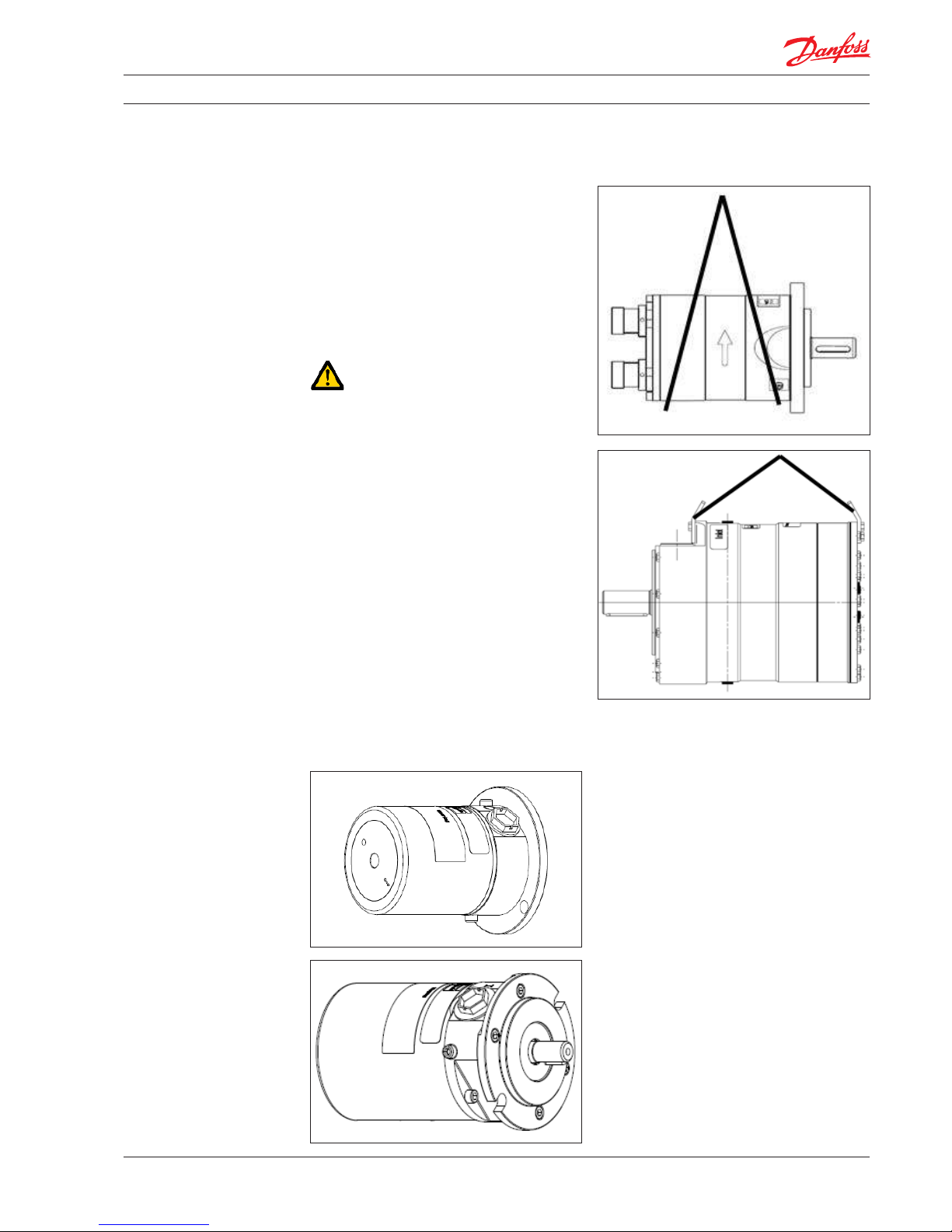
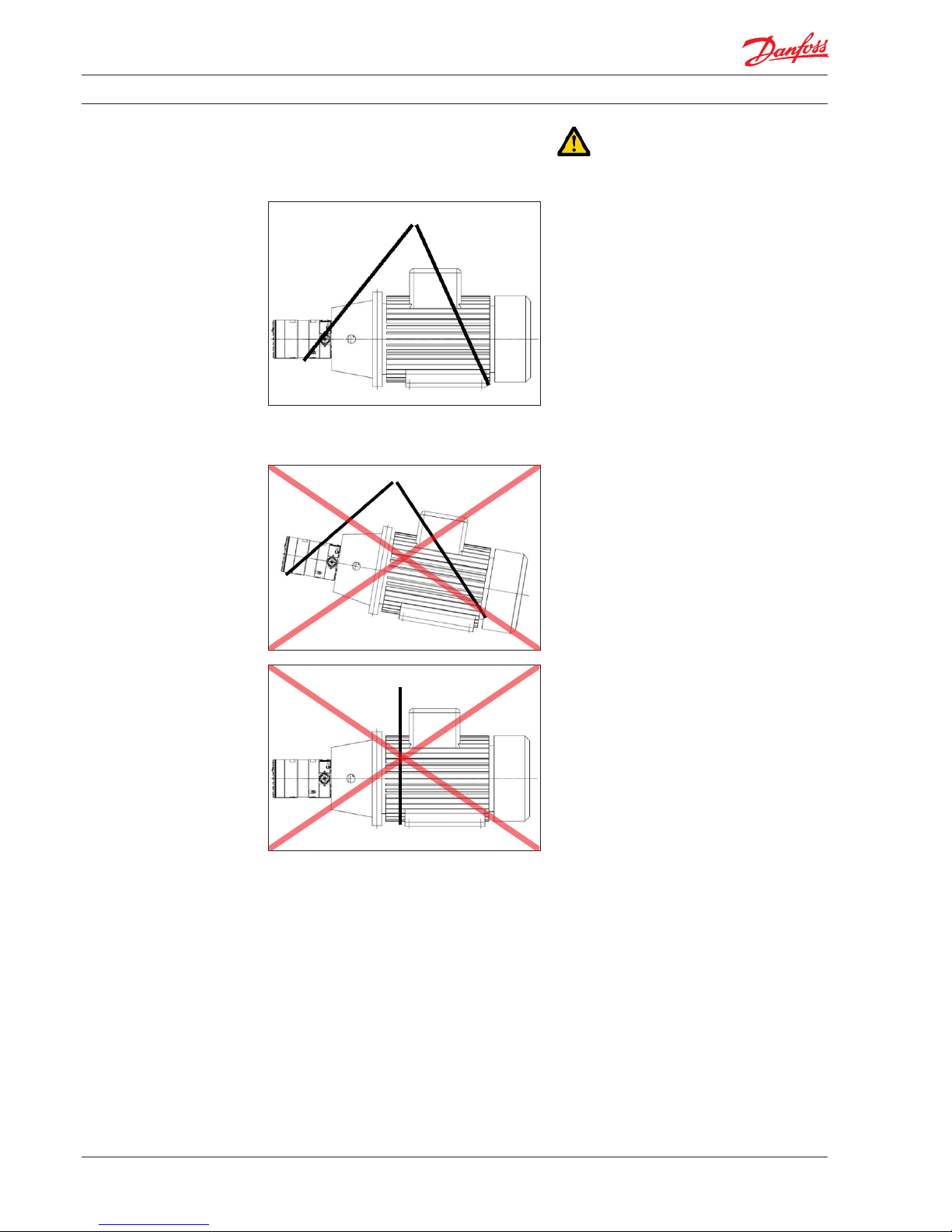
See below examples of where to/not to attach
the lifting slings on the pump unit:
Correct lifting with 2 separate slings:
When lifting the pump unit, one sling must be
attached to the electric motor and one sling
around the pump.
Only some motors and pumps have specic
lifting eyes.
Do not use connections/nozzles for lifting!
Do not use only one sling!
Make sure that the unit/load is balanced before
attempting to lift, as the centre of the mass is
dierent from pump to pump and pump unit to
pump unit.
How to mount the pump and the electric motor
correctly together, see Data sheet in appendix 1
or APP pump instruction in appendix 2.
Wrong lifting:
Incorrect lifting can result in personally injury
and/or damage to the pump unit.
4.5 Return to supplier
Please see maintenance chapter 7.
4.6 Storage
Each pump is tested before shipment and
therefore holds water, so for storage temperature and frost protection see Data sheet in
appendix 1 or APP pump instruction in appendix
2.
The pumps are NOT delivered frost protected
from the factory.
User manual Installation, Operation and Maintenance APP Pumps (APP 16-22)
11
180R9265 / IOM APP Pumps - v01 / 01.2013
5.1 Important dimensions
Physical dimensions and connections for the
pump unit are described in Data sheet,
appendix 1.
5.2 Cleanliness
It is very important that the tubes and pipes are
completely clean: no dirt, chips or burrs are
allowed. Flush all piping before connecting the
high pressure pump to ensure the system is
clean. Internal surfaces of the piping must not be
corroded. If dirt or rust is not removed, the pump
and the valves can be damaged and in the worst
case damaged beyond repair!
5.3 Fluid temperature
Before start-up, the uid and pump housing
temperature must be above the minimum
start-up temperature, see Data sheet,
appendix 1.
5.4 Electrical data
Check voltage, current frequency and rated
power on the electric motor and VFD setting
name plate on both the motor and the VFD.
5.5 Local regulations
Commissioning must always be done in
accordance with valid regulations and local
standards.
5.6 Pre mounting checklist, based on
Danfoss preferred system design
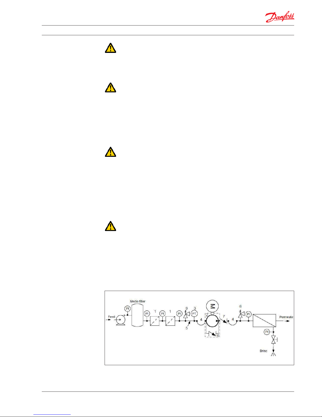
Schematic 1: Recommended system design
5. Installation and
commissioning
User manual Installation, Operation and Maintenance APP Pumps (APP 16-22)
12
180R9265 / IOM APP Pumps - v01 / 01.2013
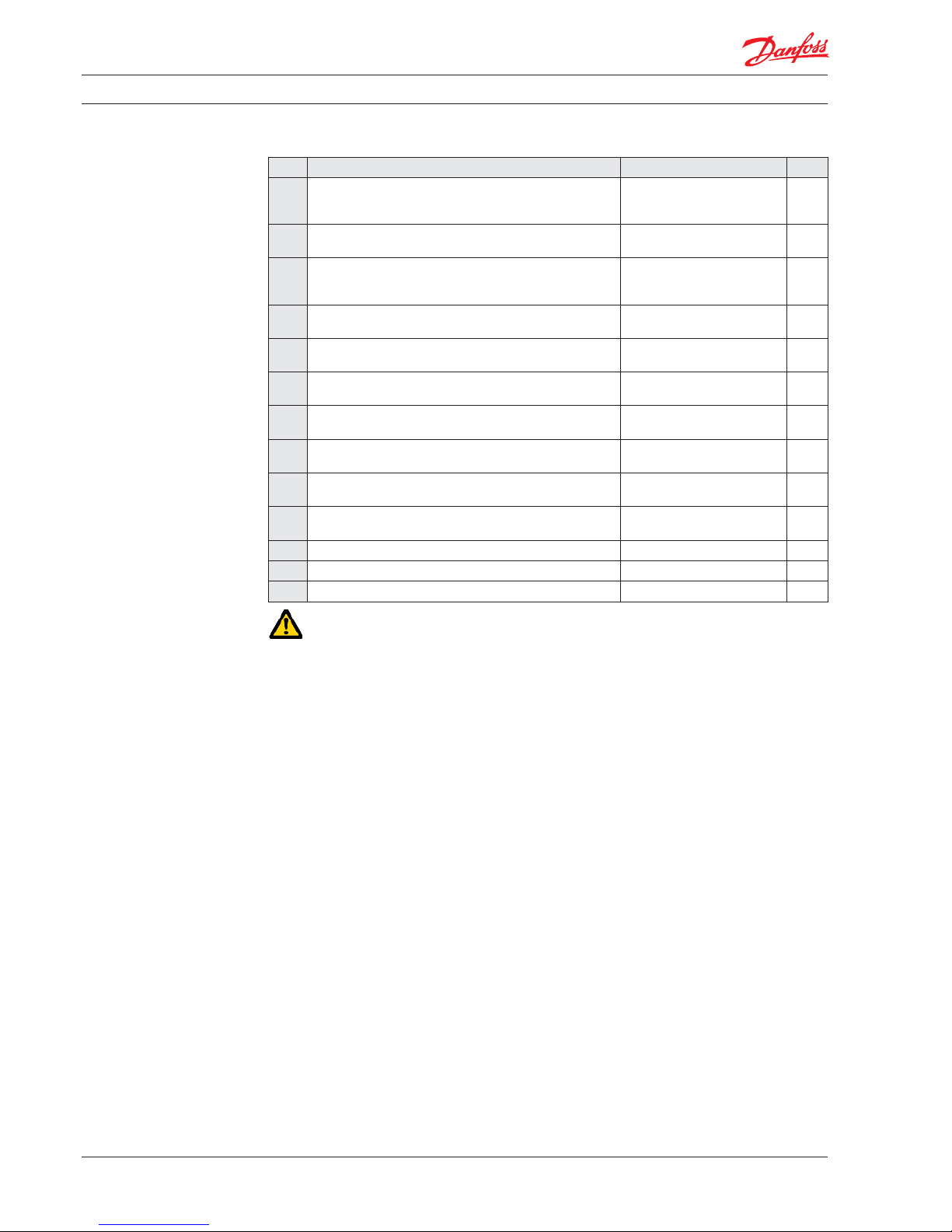
Table 1: Check points when assembling and commissioning system
Check points Comment OK ?
CP1 Ensure that the environmental conditions are safe. See Arrival inspection,
transportation, handling,
lifting and storage, chapter 4.
CP2 Minimum and maximum start-up temperature for uid and
pump.
See Data sheet or Instruction,
appendices 1 and 2.
CP3 Filtration condition (10µm absolute (ß10 = 5000) See Danfoss requirements in
Data sheet and Instruction,
appendices 1 and 2
CP4 Power supply for electric motor and VFD. See Data sheet for the used
motor and VFD, appendix 1.
CP5 Safety circuit / breaker must be sized for the motor and
environment (corrosion and humidity)
See Data sheet for the used
safety circuit.
CP6 Bolts and screws must conform to environmental conditions
as well as uid and torque requirements.
CP7 Instrumentation, pressure switch should be designed to
conform to the environment (corrosion and humidity).
See Data sheet for the used
equipment.
CP8 Check the factory settings of the safety/relief valves or
pressure relief valves (8 & 9).
See Data sheets for the used
valves.
CP9 Check the settings of the pressure transmitter/switch (3) set
at min. inlet pressure.
See Data sheet or Instruction,
appendices 1 and 2.
CP10 Check that all pressure indicators (PI) are selected to be able
to measure the system pressure range.
Scaling should at least be 1 Bar
or more precise.
CP11 Check coupling distance ( air gab – movement of the spider ) 3 – 5 mm
CP12 Check correct connections on the pump ( in & outlet)
CP13 Check piping for possible air gaps.
5.7 Lifting and positioning
Lift the pump unit onto base (Remember
vibration dampers, if needed). Fasten the motor
to the base.
See also chapter 4, Arrival inspection, transportation, handling, lifting and storage.
5.8 Mount the dierent equipment
(connections, pipes, tubes, check and safety/relief
valves, etc.)
t
The hard piping and exible hoses used must
be of proper design and must be installed in
accordance with the manufacturer’s recommendations. (see also Data sheet for Hose
and hose ttings and Instruction for
Assembling Hose kit - both available on
www.ro-solutions.danfoss.com).
t Misalignment of the hard pipes may place
stress on the pump port connection and may
damage the pump.
tPrevent excessive external pipe load.
t Do not connect piping by applying external
force (use of wrenches, crane, etc.) Piping
must be aligned without residual stress.
t Do not mount expansion joints so that their
force applies internal pressure on the pump
connections.
5.9 Electrics
All electrical installation work must be carried
out by authorized personnel in accordance with
EN60204-1 and/or local regulations. (see also
Safety, chapter 2)
Mount the safety circuit breaker, turn the circuit
o and lock it in the o position.
Mount the power cable on the electric motor.
If a VFD is used, adjust the protective motor
switch/VFD to the current limits found on name
plate of the electric motor.
5.10 Instrumentation
The pressure switch/sensor should be mounted
as close to the pump as possible. It is recommended to test the pressure/sensor switch via an
instrumentation manifold.
Mount the pressure switch/sensors according to
the manufacturer’s instructions.
5.11 Connections
Mount connections and maybe check valve(s).
Mount and tighten as specied.
User manual Installation, Operation and Maintenance APP Pumps (APP 16-22)
13
180R9265 / IOM APP Pumps - v01 / 01.2013
5.12 Ensure free ow
Ensure that the ow from safety/relief valves 8
and 9 is completely unhindered. A blocked
safety/relief valve can cause excessive build-up
of pressure and thereby cause dangerous
situations and damage to the whole system.
5.13 Verify setting of safety/relief valves
Make sure, the safety/relief valves 8 and 9 are
placed correctly.
Check the pressure settings on the name plates
of the safety/relief valves. If they are OK,
continue. Otherwise replace the safety/relief
valves.
5.14 Flush the pump
Fully open the pressure valve at the brine site.
Close all the bleeding and draining plugs on the
high pressure pump.
Start the feed pump and ensure that the ow
from the feed pump to the high pressure pump
is unhindered.
5.15 Bleed and remove air from the pump
Open bleeding plugs. Keep the plugs open until
only water leaves the high pressure pump.
5.16 Verify direction of rotation
An arrow can be found on the pump or pump
unit. The direction of rotation must always follow
the arrow.
Unlock the safety circuit breaker. Start the motor
for 1 second and observe the direction of
rotation either looking on the fan of the motor or
on the coupling true the hole in the bell housing
(not available on all bell houses). If the motor is
turning the wrong direction, switch two phases
in the connection box of the motor or reprogram
the direction in VFD.
5.17 Commissioning
tClose all the bleeding and draining plugs.
tOpen the pressure valve at the brine site.
t Switch the safety circuit breaker on for both
motor(s) and VFD(s).
tStart the feed pump.
tStart the high pressure pump.
t If a VFD or a soft starter is used a ramp up
time of minimum 10 second is required to
avoid damage of internal pump parts.
t Monitor the inlet pressure and outlet
pressure of the high pressure pump and
look for leakages.
t Check the pressure indicator function by
slowly closing the valves. The pump unit
should stop when the minimum inlet
pressure and maximum outlet pressure has
been reached.
t Adjust the pressures to the specied inlet
and outlet pressure for the system and let
the pump unit run until the electric motor
and pump temperature is stable.
t If the system is running within the system
design limits, the system is released for
operation.
5.18 Check the lter condition
Evaluate dirt found in lter, replace lter
elements, if necessary.
5.19 Instruct operator and maintenance
personnel
Before using the pump/pump unit, the personnel
must be instructed in using the pump/pump
unit, its function, components, documentation
and safety.
Danfoss oers commissioning and service at
system manufacturer’s location. Rate quotes are
oered upon request.

User manual Installation, Operation and Maintenance APP Pumps (APP 16-22)
14
180R9265 / IOM APP Pumps - v01 / 01.2013
6.1 General safety information
Before inspecting the pump unit, read the Safety
chapter 2 in this user manual.
6.2 What to listen and look for
If the following is observed, please act as
indicated:
A) Re-check all bolts and, if necessary, contact
the maintenance department in order to
have all bolts tighten to the specied levels.
B) Leakage – if a small leak dripping from the
bell housing is observed, contact the
maintenance department.
C) Leakage – if there is a large leak, the unit
should be stopped as soon as possible.
Contact the maintenance department.
D) High frequency tones – safety/relief valves
are either damaged or running very close
to their cracking pressure, stop the unit
immediately. Contact the maintenance
department.
E) Non-standard noise or vibration from the
pump requires the unit to be stopped
immediately. Contact the maintenance
department.
F) Very high temperatures – can indicate one
or more damaged parts inside the pump.
The pump then needs to be stopped
immediately and inspected before running
again. Contact the maintenance department.
G) Drop in ow and/or pressure - can indicate
wear on one or more parts inside the
pump. The pump needs to be stopped
immediately and inspected before running
again. Contact the maintenance department.
H) Other observations or troubles, please see
appendix 7, Right and Wrong or the Trouble
shooting guide, appendix 6.
Both appendices give good advises on
design, installation, wiring and troubleshooting.
If the pump is not stopped for inspection, it can
lead to damage of the pump. See also service
and warranty section in the Data sheet, appendix
1; APP pump instruction or Instruction for
recommended service intervals in appendix 2
and 4.
Danfoss oers service of the pump at the system
manufacturer’s location as well as training in
servicing the pump. Quotes are oered upon
request.
Danfoss recommends at the same time also to
check the lter and membrane condition and
evaluate dirt found, replace lter and membrane
elements if necessary.
6. Operation of motor
pump unit

User manual Installation, Operation and Maintenance APP Pumps (APP 16-22)
15
180R9265 / IOM APP Pumps - v01 / 01.2013
7. Maintenance and
service of the pump
unit
7.1 General safety information
Before servicing the pump unit, it is necessary to
read and understand this user manual, especially
the Safety, chapter 2. Remember to wear suitable
safety equipment according to Safety, chapter 2.
7. 2 Service and inspection interval for the
pump
Maintenance and service intervals are depending
on the cleanness level of the water, hydraulic
load and temperature of the pump unit. The
most important parameter is the cleanness of the
water.
See the section Service and warranty in the Data
sheet, appendix 1, APP pump instruction and
Instruction for recommended service intervals in
appendix 2 and 4.
For spare parts and service tools, please see Parts
list, appendix 5.
Danfoss oers service of the pump at the system
manufacturer’s location and training in servicing
the pump. Quotes are oered upon request.
7. 3 Shut down of the system
A) Open the pressure valves at the brine site
to release the pressure.
B) Stop the high pressure pump.
C) Stop the feed pump.
D) Turn on the motor safety circuit breaker for
both the high pressure pump, the feed
pump and the VDF if used and lock them.
Only the employees servicing the pump
unit should be able to unlock/activate the
switch again.
E) Open bleeding and drain plugs. Wait until
the pump and system are emptied for
water.
F) Slowly unscrew and remove the bolts and
gaskets from the in/out hoses or pipes, be
careful about jets of water. Be aware that
there still can be pressure in the system,
which will be released when unscrewing
and removing the bolts and gaskets.
G) Attach the lifting equipment to the pump
unit. For instructions on lifting the
complete pump unit, see chapter 4, Arrival
inspection, transportation, handling, lifting
and storage.
H) For the small pumps unscrew the bolts
holding the pump to the bell housing and
for the bigger pumps, unscrew the bolts
holding the pump and bell housing to the
motor and afterwards unscrew the bolts/
nuts holding the pump and bell housing
together.
I) Carefully pull the pump out of the bell
housing by using lifting equipment, if
necessary.
J) Hold the pump in dierent positions above
a drip tray; this should allow most of the
left-over water trapped in the pump to drip
out. Clean and dry the pump surface and
plug the bleeding and draining plugs.
K) Move the pump to a clean and safe location
where the pump can be inspected/
serviced.
7. 4 Disassembling and assembling the
pump unit
A) Remove all connections from the pump.
B) Disassemble the pump according to the
Disassembling and Assembling Instruction
(availabl e at w ww.ro-solutions.danfoss.com
At the website you can also nd the
Changing pistons instructions for APP 11-13
and APP 16-22 as well as for APP 21-38).
Clean all the parts and surfaces with a uid
compatible with the materials found in the
pump. Wipe the parts clean and dry with a
dry and lint-free cloth.
C) Inspect all parts including shaft seal and if
necessary, replace them; see Parts list,
appendix 5 and APP pump instruction,
appendix 2 or general instruction for
Recommended service intervals, appendix
4.
D) If the pump is going to be returned to
Danfoss for repair or a warranty claim, it is
important that Danfoss, besides your
contact information and reason for
returning, gets the below information
before shipping.
After Danfoss has been informed about the
return, you will receive a return number
and a template to ll out. One copy should
be attached to the shipment and one copy
should be sent to the E-mail address on the
template.
Returns without a return number will be
rejected !!!

User manual Installation, Operation and Maintenance APP Pumps (APP 16-22)
16
180R9265 / IOM APP Pumps - v01 / 01.2013
7. 5 Assembling the pump unit
Assemble the pump according to the Disassembling and Assembling Instruction
(availabl e at w ww.ro-solutions.danfoss.com).
7. 6 Procedure for mounting pump back
onto electric motor
Do always follow the procedure delivered with
the instructions from the coupling manufacturer!
Mount the exible coupling and bell housing
according to the Data sheet, appendix 1 and APP
pump instruction, appendix 2.
7.7 Getting the pump unit back into
operation
Find instructions of how to put the pump unit
back into operation in chapter 4, Arrival inspection, transportation, handling, lifting and storage
and Installation and commissioning, chapter 5.
7. 8 Storage of the pump
If the pump has to be shut down for a longer
period or put on the shelf, instructions can be
found in Storage-chapter in Data Sheet, appendix 1 or APP pump instruction, appendix 2.

User manual Installation, Operation and Maintenance APP Pumps (APP 16-22)
17
180R9265 / IOM APP Pumps - v01 / 01.2013
8. Troubleshooting and
scrapping criteria
8.1 General safety information
Before inspecting the pump unit, it is necessary
to read and understand this user manual,
especially the Safety chapter 2.
Remember to wear suitable safety equipment
according to Safety chapter 2.
8.2 Operational conditions which can cause
pump failures
The following conditions can cause a pump
failure :
t5IFQVNQJTSVOOJOHESZ
t5IFJOMFUQSFTTVSFJTUPPIJHI
t5IFJOMFUQSFTTVSFJTUPPMPX
t5IFWJTDPTJUZPGUIFøVJEJTUPPIJHI
t5IFUFNQFSBUVSFPGUIFøVJECFJOH
pumped is too high.
t5IFBNCJFOUUFNQFSBUVSFJTUPPIJHI
t5IFQVNQJTSVOOJOHBHBJOTUBCMPDLFE
port/closed manual valve.
t5IFQVNQJTPQFSBUJOHBUBQSFTTVSFBCPWF
the operational specication.
t5IFQVNQJTSVOOJOHXJUIBOPOTQFDJöFE
approved uid.
t5IFQVNQJTSVOOJOHJOUIFXSPOH
direction.
t5IFöMUSBUJPOJTJOTVóDJFOU
t5IFQVNQJTOPUCFJOHTFSWJDFEBDDPSEJOH
to Danfoss specications (end of life).
t5IFSFJTFYDFTTJWFNFDIBOJDBMMPBEPOUIF
shaft coupling and piping.
8.3 Mechanical failure
If the pump is running dry, the temperature will
quickly increase which can be dangerous,
depending on how long time the pump is
running dry.
If there is any leaking at start up or leaking arises
during operation, the high pressure can lead to
eye or skin damage.
Leaking can result in ooding, which again can
cause a risk of slipping, tripping or falling.
If water is dripping into the electric motor; it can
lead to electric shock, re, short of circuit or even
death. In order to avoid water dripping into the
electric motor, see Installation and commissioning, chapter 5 and Operation, chapter 6.
Electrical
hazard
8.4 Electrical failure
If the wiring/connection of the electric motor is
not correct or the earth connection is missing, it
can lead to electric shock, burn damages, re or
even death.
If a VFD is used and wrongly programmed, it can
damage the pump and lead to high temperatures or other dangers.
Therefore all electrical installation work must
only be carried out by authorized personnel in
accordance with EN60204-1 and/or local
regulations.
8.5 Responsibility
Danfoss takes no responsibility for any other
abnormal injuries, risks or damages that could
arise caused by abnormal conditions, vibrations,
corrosion, abrasives, foreign objects or excessive
temperatures and shall not be liable for any
consequential or incidental damages.
8.6 Scrapping criteria
Whether the pump can be repaired or need to be
scrapped depends on how damaged the internal
parts are or how damaged the whole unit is.
Please use appendix 6, Trouble shooting guide as
guideline or send the pump to Danfoss headquarter in Denmark for evaluation.
For other observations or troubles, please see
appendix 7, Right and Wrong which gives good
advises in design, installation, wiring and
troubleshooting.

User manual Installation, Operation and Maintenance APP Pumps (APP 16-22)
18
180R9265 / IOM APP Pumps - v01 / 01.2013
Danfoss ca n accept no responsi bility for pos sible errors in ca talogues, bro chures and other pr inted material. D anfoss reserve s the right to alter it s products wit hout notice.
This also ap plies to produc ts already on orde r provided that su ch alterations ca n be made without su bsequential cha nges being nece ssary in speci cations alread y agreed.
All trade marks in this mater ial are proper ty of the respec tive companies . Danfoss and the Danf oss logotyp e are trademark s of Danfoss A/S. Al l rights reser ved.
Danfoss A/S
High Pressure Pumps
DK-6430 Nordborg
Denmark
A
Address
. . . . . . . . . . . . . . . . . . . 6, 7, 15
Air bubbles . . . . . . . . . . . . . . . . . . . . . 8
Appendix
. . . .7, 8, 9, 10, 11, 12, 14, 15, 16, 17
Application range
. . . . . . . . . . . . . . . . . 8
Approval . . . . . . . . . . . . . . . . . . . . . . . 6
Arrival
. . . . . . . . . . . . . . . . . 9, 12, 15, 16
Assembling
. . . . . . . . . . . . . . . . 12, 15, 16
B
Bleed
. . . . . . . . . . . . . . . . . . . 7, 8, 13, 15
C
Checklist . . . . . . . . . . . . . . . . . . . . . . 11
Check points
. . . . . . . . . . . . . . . . . . . 12
Chemicals . . . . . . . . . . . . . . . . . . . . . . 8
Cleanliness
. . . . . . . . . . . . . . . . . . . . 11
Commissioning . . . . . .6, 7, 11, 12, 13, 16, 17
Connections
. . . . . . . . . . 7, 9, 10, 11, 12, 15
Coupling . . . . . . . . . . . . . . 7, 12, 13, 16, 17
D
Danger
. . . . . . . . . . . . . . . . . . . .7, 13, 17
Data sheet . . . . . . 7, 8, 9, 10, 11, 12, 14, 15, 16
Declaration of Conformity
. . . . . . . . . 5, 6
Design
. . . . . . . . . . . . 7, 8, 9, 11, 12, 14, 17
Distributor. . . . . . . . . . . . . . . . . . . . 6, 8
Dimensions
. . . . . . . . . . . . . . . . . . . 8, 11
Disassembling . . . . . . . . . . . . . . . . 15, 16
E
Electric motor
. 6, 7, 8, 9, 10, 11, 12, 13, 16, 17
Electrical failure
. . . . . . . . . . . . . . . . . 17
Electrical hazard . . . . . . . . . . . . . . . . . . 6
Electrics
. . . . . . . . . . . . . . . . . . . . . . 12
EU Declaration of Conformity
. . . . . . . . . 5
F
Fail ure
. . . . . . . . . . . . . . . . . . . . . .8, 17
Filter condition . . . . . . . . . . . . . . . . . . 13
Filtration . . . . . . . . . . . . . . . . . . 8, 12, 17
Flow
. . . . . . . . . . . . . . . . . . . 7, 8, 13, 14
Fluid
. . . . . . . . . . . . . . . . . . .11, 12, 15, 17
Flush
. . . . . . . . . . . . . . . . . . . . . . 11, 13
G
General information
. . . . . . . . . . . . . . . 7
Guideline . . . . . . . . . . . . . . . . . . . . . 17
H
Handling. . . . . . . . . . . . . . . 7, 9, 12, 15, 16
I
Inspection. . . . . . . . . . . . . 9, 12, 14, 15, 16
Installation
. . . . . . . . .6, 7, 11, 12, 14, 16, 17
Instruction. . . . . . . . 6, 7, 8, 10, 12, 14, 15, 16
Instrumentation
. . . . . . . . . . . . . . . .6, 12
Introduction . . . . . . . . . . . . . . . . . . . .6
M
Maintenance
. . . . . . . . . .6, 7, 10, 13, 14, 15
Mechanical failure. . . . . . . . . . . . . . . . 17
Mounting
. . . . . . . . . . . . . . . . . . . . . 16
N
Name plate
. . . . . . . . . . . . . . 9, 11, 12, 13
Noise
. . . . . . . . . . . . . . . . . . . . . . . . 14
L
Leaking. . . . . . . . . . . . . . . . . . . . . . . 17
Lifting
. . . . . . . . . . . . . 6, 9, 10, 12, 15, 16
Local regulations . . . . . . . . . 6, 7, 11, 12, 17
O
Operation
. . . . . . . . .6, 7, 8, 9, 13, 14, 16, 17
Operational conditions . . . . . . . . . . .7, 17
P
Piping. . . . . . . . . . . . . . . . . . 8, 11, 12, 17
Positioning
. . . . . . . . . . . . . . . . . . . . 12
Preferred system design
. . . . . . . . . . . 7, 11
Pre mounting . . . . . . . . . . . . . . . . . . . 11
Protection . . . . . . . . . . . . . . . . . . 6, 7, 10
R
Relief valve
. . . . . . . . . . . . . . . .12, 13, 14
Responsibility . . . . . . . . . . . . . . . 6, 7, 17
Return
. . . . . . . . . . . . . . . . . . . . . 10, 15
Rotation
. . . . . . . . . . . . . . . . . . . . . . 13
S
Safety
. . . . . . . . . .6, 7, 8, 9, 12, 13, 14, 15, 17
Safety valve . . . . . . . . . . . . . . . . . . . . .7
Scrapping criteria
. . . . . . . . . . . . . . . . 17
Serial number
. . . . . . . . . . . . . . . . . . . 4
Servicing. . . . . . . . . . . . . . . . . 6, 7, 14, 15
Shut down. . . . . . . . . . . . . . . . . . . 15, 16
Space requirement
. . . . . . . . . . . . . . . . 8
Spare part . . . . . . . . . . . . . . . . . . . . . 15
Start up
. . . . . . . . . . . . . . . . . . . . . . 7, 17
Storage . . . . . . . . . . . . . . . 9, 10, 12, 15, 16
Symbols
. . . . . . . . . . . . . . . . . . . . . . . 6
System . . . . . . . . . . 6, 7, 8, 11, 12, 13, 14, 15
Systems
. . . . . . . . . . . . . . . . . . . . . 7, 8
T
Table of content
. . . . . . . . . . . . . . . . . . 2
Technical data . . . . . . . . . . . . . . . . . . . 8
Tem pe rat ure
. . . . .7, 10, 11, 12, 13, 14, 15, 17
Transportation
. . . . . . . . . . . 6, 9, 12, 15, 16
Trouble shooting . . . . . . . . . . . . . . 14, 17
V
Valve
. . . . . . . . . . . . 7, 11, 12, 13, 14, 15, 17
W
Warning
. . . . . . . . . . . . . . . . . . . . . 6, 9
Subject index

Front page for Appendices
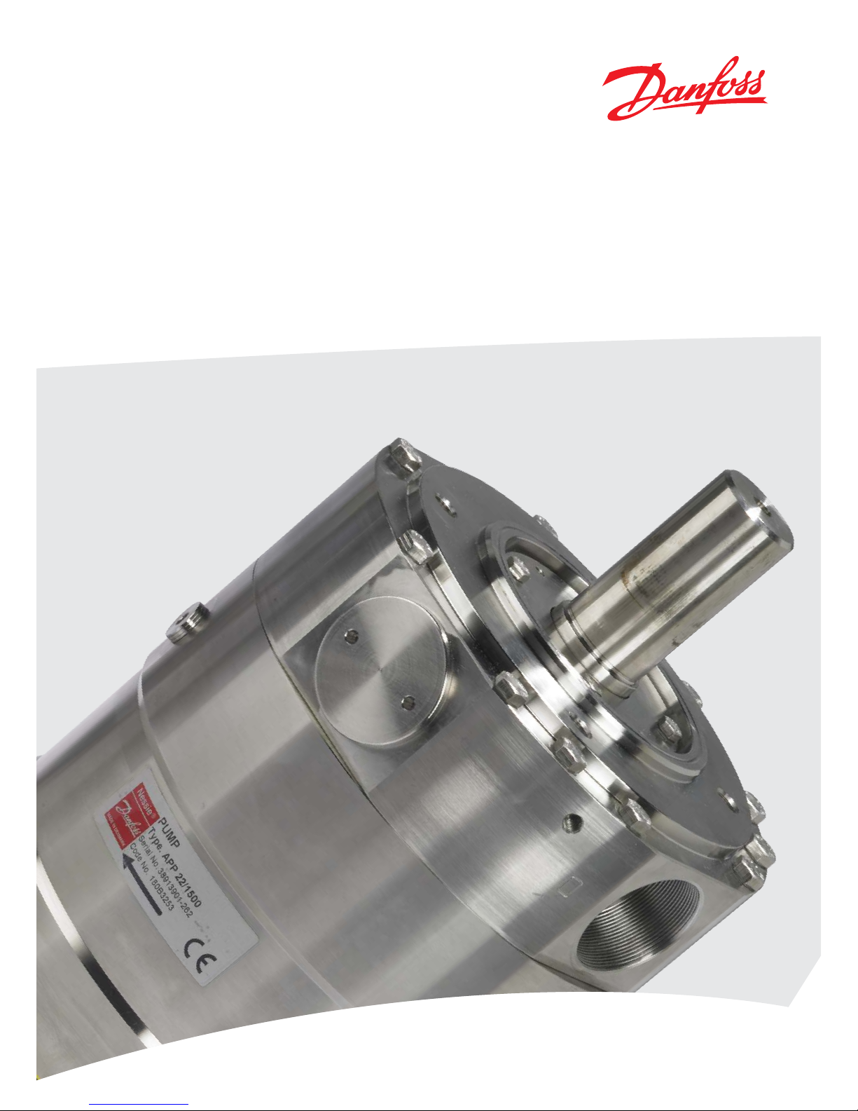
APP 16-22
User manual
Appendices for Installation,
Operation and Maintenance Manual
APP pumps (APP 16-22)
MAKING MODERN LIVING POSSIBLE

User manual Appendices for IOM Manual for APP Pumps (APP 16-22)
2
180R9265 / IOM APP 16-22 Append ices - v02 / 01.2013
Table of Contents 1. Data sheet for APP 16-22 pumps (521B1183)..............................................3
2. APP pump instruction APP 11-13 and APP 16-22 (180R9223) .............................15
3. IOM Electric motors (180R9230)..........................................................27
4. Recommended service intervals for APP pumps (180R9199) . . .. . . . . . .. . . . .. . . . . . .. . . . .. .31
5. APP parts list (521B0941)................................................................35
6. Trouble shooting guide .. ... .. ... .. ..... ..... .. ... .. ..... ..... .. ... .. ..... ..... .. ... .. .41
7. Right and wrong (180R9042) ...........................................................51
1. Data sheet for APP
16-22 pumps (521B1183)
ro-solutions.com
Data sheet
Data sheet
APP 16-22
MAKING MODERN LIVING POSSIBLE
4
180R9265 / IOM APP 16-22 Append ices - v02 / 01.2013
Data sheet APP 16-22
APP 16-22 pumps are designed to supply low
viscosity and corrosive uids under high
pressure, e.g. in seawater reverse osmosis
ltration applications and for high pressure salt
water pumping.
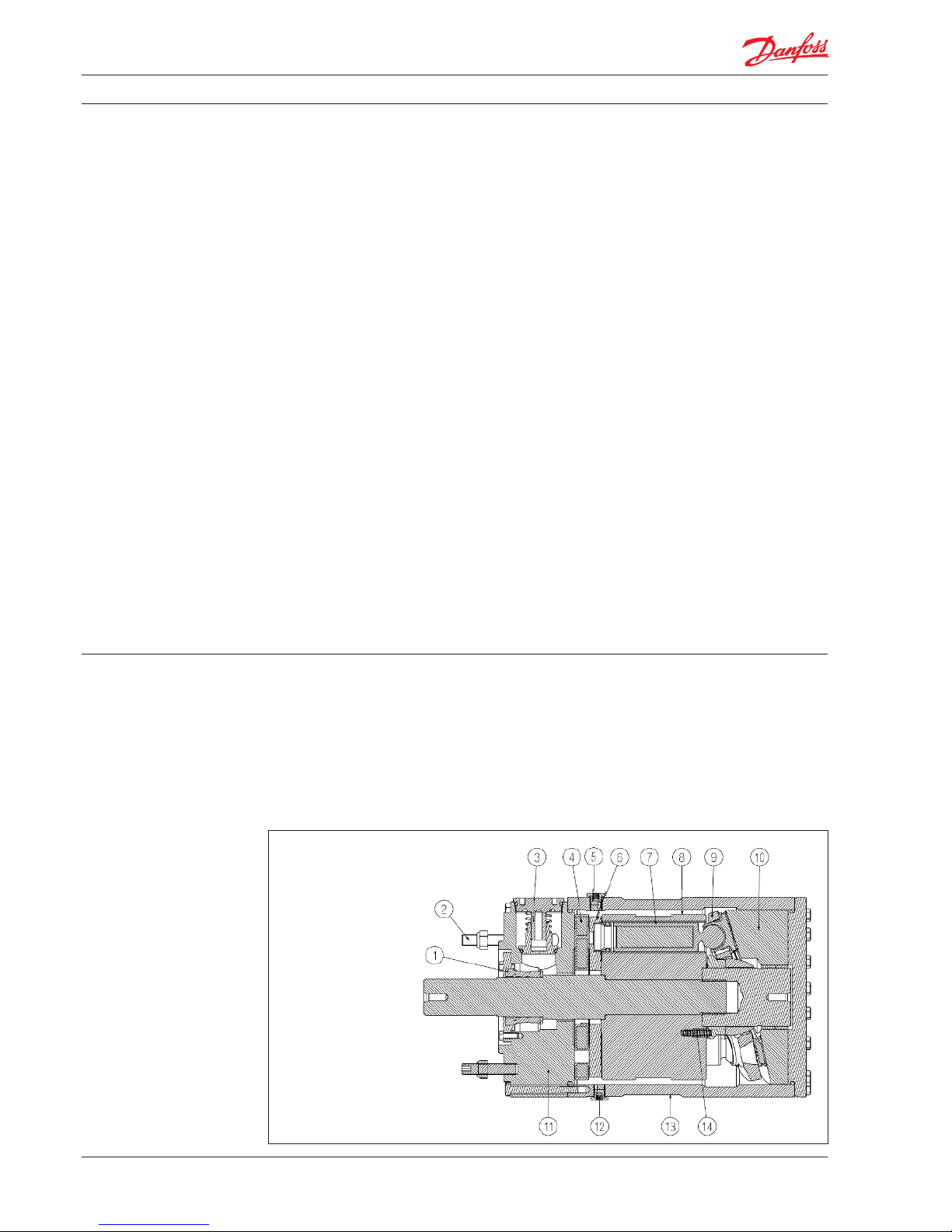
The pumps are based on the positive displacement principle (axial piston design) which
enables a very light and compact design, and
they are designed so that the lubrication of the
moving parts in the pumps is provided by the
uid itself. No oil lubrication is thus required.
The pumps are supplied with an integrated
ushing valve that allows the salt water to ow
from inlet to the outlet, when the pump is not
running.
1. General information
1: Shaf t Sealing
2: Bolts for bell housing
3: Flushing valve
4: Port plate
5: Bleeding plug
6: Valve/thrust plate
7: Piston/shoe
8: Cylinder barrel
9: Retainer ring
10: Swash plate with bearing
11: Port ange with bearing
12: Drain plug
13: Housing
14: Springs
1. General information
2. Benets
3. Technical data
4. Variants
5. Flow at dierent rpm
6. Flushing valve
7. Power requirements
8. Temperature and corrosion
8.1 Operation
8.2 Storage
9. Noise level
10. Filtration
11. Dimensions
12. Dimensions, complete unit
13. Installation
13.1 Mounting
13. 2 Open-ended system with direct water supply
13. 3 RO system with APP pump
14. Service
14.1 Warranty
14. 2 Maintenance
14. 3 Repair
Data sheet for
APP 16-22 pumps (521B1183)
Table of Contents
5
180R9265 / IOM APP 16-22 Append ices - v02 / 01.2013
Data sheet APP 16-22
t One of the smallest and lightest pumps on
the market
t Can be powered by a combustion engine
provided that a special coupling is used.
t Long service life / No preventive mainte-
nance required in the warranty period.
t Generates insignicant pulsations in the
pressure line.
tNo oil lubricant required
tIntegrated ushing valve
t All parts of the pump are made of non-
corrosive materials, e.g. Duplex (EN1.4462/
UNS S31803-S32205) and Super Duplex
(EN1.4410/UNS S32750) stainless steel and
carbon reinforced PEEK
tHigh eciency
2. Benets
3. Technical data
APP Pumps APP 16
120 0
APP 16
150 0
APP 17
120 0
APP 17
150 0
APP 19
120 0
APP 19
150 0
APP 22
120 0
APP 22
150 0
Code number 180 B325 4 18 0B325 0 18 0B32 55 180 B3251 180B 3256 18 0B32 52 180 B3257 180B 3253
Geometric displacement cm³/rpm 235 18 5 252 19 8 272 220 311 252
in³/rpm 14. 3 11 . 3 15. 4 12 .1 16 .6 13. 4 19 .0 15. 4
Rated ow at max speed
1)
m³/h 16 15. 8 17. 2 16 .9 18. 8 18. 8 21.5 21.7
gpm 70.4 69.6 75.7 74 .4 82.8 82.8 94.7 95.5
Outlet min. Pressure
2)
bar 30 30 30 30 30 30 30 30
psi 435 435 435 435 435 435 435 435
Outlet max. Pressure,
continuous
3)
bar 80 70 80 70 80 70 80 70
psi 116 0 1015 116 0 1015 1160 1015 116 0 1015
Inlet min. Pressure bar 2 2 2 2 2 2 2 2
psi 29 29 29 29 29 29 29 29
Inlet max. Pressure, continuous bar 5 5 5 5 5 5 5 5
psi 72.5 72.5 72.5 72.5 72.5 72.5 72.5 72.5
Inlet max. Pressure, peak bar 10 10 10 10 10 10 10 10
psi 145 145 145 145 145 145 145 145
Max. Speed continuous rpm 120 0 15 00 1200 150 0 120 0 15 00 1200 150 0
Min. Speed continuous rpm 700 70 0 700 700 700 700 700 700
Power requirement at max.
speed and 60 bar outlet
pressure
kW 32 31 35 33 38 37 43 43
hp 42 .9 41.6 46.9 44.3 51.0 49.6 57.7 57.7
Torque at 60 bar outlet
pressure
Nm 258 196 276 210 299 236 341 273
lbf-ft 190 .3 14 4.6 203.6 15 4.9 220.5 174.1 251.5 201.4
Weight kg 78 78 78 78 78 78 78 78
lb 172 17 2 17 2 17 2 172 17 2 17 2 172
Integrated ushing valve Yes Yes Ye s Yes Yes Yes Ye s Yes
1)
Typical average ow at 60 bar (870 psi)
2)
For lower pressure, please contact Danfoss
RO Sales Organization
3)
For higher pressure, please contact Danfoss
RO Sales Organization
The pump is designed according to EN809.
All parts included in the pumps are designed to
provide long service life, i.e. long service life with
a constantly high eciency and minimum
service required.
The pumps are xed displacement pumps in
which the ow is proportional to the number of
revolutions of the input shaft and the pump
displacement.

6
180R9265 / IOM APP 16-22 Append ices - v02 / 01.2013
Data sheet APP 16-22
t Available as ATEX certied. Category 2,
zone 1 and category 3, zone 2.
t Available with material certicates on
wetted parts
For more details on the variants, please contact
the Danfoss RO Solutions Sales Organisation
4. Variants
5. Flow at dierent rpm When using the diagrams shown below, it is easy
to select the pump which ts the application
best if the ow required and the rotation speed
(rpm) of the pump are known.
5,00
8,00
11,00
14,00
17,00
20,00
23,00
700 800 900 1000 1100 1200
m3/h
rpm
1200 rpm version
APP 22
APP 19
APP 17
APP 16
5,00
8,00
11,00
14,00
17,00
20,00
23,00
700 800 900 1000 1100 1200 1300 1400 1500
m3/h
rpm
1500 rpm version
APP 22
APP 19
APP 17
APP 16
Furthermore, these diagrams shows that the ow
can be changed by changing the rotation speed
of the pump. The ow/rpm ratio is constant, and
the “required “ ow can be obtained by changing
the rotation speed to a corresponding value.
Thus, the required rpm can be determined as:
Required ow × Rated rpm
Required rpm =
Rated ow

7
180R9265 / IOM APP 16-22 Append ices - v02 / 01.2013
Data sheet APP 16-22
6. Flushing valve
0
0,5
1
1,5
2
2,5
3
0 50 100 150 200 250 300 350 400
Pressure drop [bar]
Flow [l/min]
Flushing Valve characteristic
7. Power requirements
Pump
model
Flow Pressure rpm Calc.
factor
60 bar 70 bar 80 bar
l/min m
3
/h gpm 870 psi 1015 psi 1160 psi
APP 16
1200
267 16.0 70.5 32 kW 38 kW 43 kW 1180 496
APP 16
1500
263 15.8 69.5 31 kW 36 kW 41 kW 1480 511
APP 17
1200
287 17.2 75.8 35 kW 40 kW 46 kW 1180 498
APP 17
1500
281 16.9 74.2 33 kW 38 kW 44 kW 1480 513
APP 19
1200
314 18.8 82.9 38 kW 44 kW 50 kW 1180 499
APP 19
1500
313 18.8 82.7 37 kW 43 kW 49 kW 1480 509
APP 22
1200
358 21.5 94.6 43 kW 50 kW 57 kW 1180 501
APP 22
1500
362 21.7 95.6 43 kW 50 kW 57 kW 1480 507
The power requirements can be determined using one of the following guiding equations:
l/min × bar 16.7 × m
3
/h × bar 0.26 × gpm × psi
Required power = [kW] or [kW] or [kW]
Calc. factor Calc. factor Calc. factor
1 hp = 0.75 kW
1 kW = 1.34 hp
1 gpm = 3.79 l/min
1 l/min = 0.26 gpm
1 m
3
/h = 4.40 gpm
1 gpm = 0.23 m
3
/h

8
180R9265 / IOM APP 16-22 Append ices - v02 / 01.2013
Data sheet APP 16-22
8.1 Operation
The chart on the next page illustrates the
corrosive resistance of dierent types of stainless
steel related to NaCl concentration and temperature.
All critical parts of the APP water pump are made
of Super Duplex.
If the water pump is operated at high salinity,
always ush the water pump with fresh water at
operation stop in order to minimize the risk of
crevice corrosion.
8.2 Storage
Frost protection is required at temperatures
below 2°C. Danfoss recommends to use DOWFROST from DOW Chemical Company or Chilsafe
mono propylene glycol from Arco Chemical
Company.
8. Temperature and
corrosion
316L
Super Duplex
80
º
C
70
60
50
40
30
20
100
160 1600
1000
16000
10 000
160000
100 000
CI
-
ppm
NaCI
ppm
Duplex
NaCl vs. temperature
9. Noise level The sound pressure levels, L PA, 1 m *) db(A) for
APP 16-22 pumps are typically 82 dB(A) at
60 bar/1500rpm and 84 dB at 80 bar/1500rpm.
Generally, noise will be reduced if speed is
reduced and vice versa. Use exible hoses in
order to minimize vibrations and noise.
Since the pump is typically mounted on a bell
housing or frame, the noise level must be
determined for the complete unit (system). It is
therefore very important that the motor/pump
unit is mounted correctly on a frame with
antivibration isolation to minimize vibrations and
noise.
The noise level is inuenced by:
t The speed of the pump, high rpm create
more noise than low rpm
t Rigid mounting of the pump generates
more noise than exible mounting
t Pipe mounting direct to the pump
increases the noise level compared to a
exible hose
t If using a VFD the motors can produce
higher noise values depending on the
operation point.
t
*) 1 meter from the pump unit surfaces (reference box) acc. to EN ISO 20361 section 6.2.
Deviation σTOT = ± 1,6 dB(A)
Fluid temperature:
+2° C to +50° C (+35.6° F to 122° F) - dependent
on the NaCl concentration
Ambient temperature:
+2° Cto +50° C (+35.6° F to 122° F)
Storage temperature:
-40° C to +70° C (-40° F to 158° F) – provided
that the pump is drained of uid and stored
”plugged”.

9
180R9265 / IOM APP 16-22 Append ices - v02 / 01.2013
Data sheet APP 16-22
As water has very low viscosity, the APP pumps
have been designed with very narrow clearance
in order to control internal leakage rates and
improve component performance. Therefore it is
important that the inlet water is ltered properly
to minimize the wear of the pump.
The main lter must have a ltration eciency of
99.98% at 10 μm. We recommend to use
precision depth lter cartridges rated 10μm abs.
ß10>5000 (equivalent to a ltration eciency of
99.98%). Bag lters and string wound lter
cartridges typically have only 50% ltration
eciency. This means that for each 100,000 particles reaching the lter, 50,000 particles pass
through it compared to only 20 particles in a
lter with an eciency of 99.98%.
For more information on the importance of
proper ltration, please consult our publication
“Filtration” (code number 521B1009), which also
will provide you with an explanation of ltration
denitions and a guidance on how to select the
right lter.
10. Filtrat ion
11. Dimensions
Outlet
O I

10
180R9265 / IOM APP 16-22 Append ices - v02 / 01.2013
Data sheet APP 16-22
12. Dimensions,
complete unit
Description APP 16 – APP 22
Parallel key,
DIN 6885
mm
12 × 8 × 70
In 0.47 × 0.31 × 2.76
Bleeding G ¼”, Hexagon AF
= 6 mm
Inlet port M52 x 1.5; depth 21 mm
Outlet port M52 x 1.5; depth 21 mm
Pump mounting ange 125 B 4
Accessories Ty pe Code no.
2” inlet hose
kit 2 m/79”
2” Victaulic 18 0Z02 98
2” inlet Vic.
Super Duplex
2” Victaulic 18 0Z0165
Non-return
valve (outlet)
Super Duplex
2” Victaulic
(OD 63 mm)
180 H025 6
For more details on the accessories, please contact the Danfoss RO Solutions Sales Organisation.
Accessories

11
180R9265 / IOM APP 16-22 Append ices - v02 / 01.2013
Data sheet APP 16-22
13. Installation 13.1 Mounting
The gure below illustrates how to mount the
pump and connect it to the electric motor/
combustion engine.
If alternative mounting is required, please
contact Danfoss RO Sales Organization for
further information.
To ensure easy mounting of the exible coupling
without using tools, the tolerances must be
dimensioned accordingly.
Note: Any axial and radial loads on the pump
shaft must be avoided.
Pump A (mm)
(P)
B (mm)
(HD)
C (mm)
(H)
D (mm)
(A)
E (mm)
(B)
F (mm)
(LB)
G (mm) IEC Electric motor
APP 16 450 560 225 356 286 675 262 37 kW, IEC 225 S4
APP 17 450 560 225 356 311 705 262 45 kW, IEC 225 M4
APP 19 55 0 615 250 406 349 775 265 55 kW, IEC 250 M4
APP 22 55 0 680 280 457 368 835 265 75 kW, IEC 280 S4
Note: Examples of dierent pump/motor sizes
and drawing dimensions are only for IEC
motors and couplings. Please always check
required motor power and dimensions.
13. 2 Open-ended system with direct water
supply
In order to eliminate the risk of cavitation, a
positive inlet pressure is always to be maintained.
Please see technical data (section 3.) for specic
pressure values.
1. Place the lter (1) in the water supply line in
front of the pump.
2. Place a monitoring pressure switch (2) - set
at min. inlet pressure - between lter and
pump inlet.
The monitoring switch must stop the pump
at pressures lower than min. inlet pressure.
Please see technical data (section 3.) for
specic pressure values
3. Install a low pressure safety valve or a
pressure relief valve (3) in order to avoid
system or pump damage in case the pump
stops momentarilly or spinning backwards.
3
Note: If a non return valve is mounted in the
inlet line, a low pressure relief valve is also
required between non return valve and pump
as protection against high pressure peaks.
A: Flexible coupling
B: Bell housing
C: Motor shaf t
Ensure 3-5 mm (0.12-0.2 inches) air gap
between coupling parts.

12
180R9265 / IOM APP 16-22 Append ices - v02 / 01.2013
Data sheet APP 16-22
13. 3 RO system with APP pump
1. Dimension the inlet line to obtain minimum pressure loss (large ow, minimum
pipe length, minimum number of bends/
connections, and ttings with small
pressure losses).
2. Place an inlet lter (1) in front of the APP
pump (2). Please consult section 10,
“Filtration” for guidance on how to select
the right lter. Thoroughly clean pipes and
ush system prior to start-up.
3. Place a monitoring pressure switch (3) set
at min. inlet pressure between lter and
pump inlet. The monitoring switch must
stop the pump at pressures lower than
minimum pressure.
4. Use exible hoses (4) to minimize vibrations
and noise.
5. In order to eliminate the risk of damage
and cavitation, a positive pressure at the
inlet (5) is always to be maintained at min.
inlet pressure and max. inlet pressure.
Recommend to install safety valve or a
pressure relief valve (9) in order to avoid
high pressure peaks in case the pump stops
momen tarilly or spinning backwards.
6. For easy system bleeding and ushing, a
bypass non-return vavle (6) is integrated in
the APP pump.
7. A non-return valve (7) in outlet can be
installed in order to avoid backspin of the
pump. The volume of water in the membrane vessel works as an accumulator and
will send ow backwards in case of the
pump stops momentarily.
8. A safety valve or a pressure relief valve (8)
can be installed in order to avoid system
damage as the Danfoss APP pump creates
pressure and ow immediately after
start-up, regardless of any counterpressure.
Note: If a non return valve is mounted in the
inlet line, a low pressure relief valve is also
required between non return valve and pump
as protection against high pressure peaks.
14. Service 14.1 Warranty
Danfoss APP pumps are designed for long
operation, low maintenance and reduced
lifecycle costs.
Provided that the pump has been running
according to the Danfoss specications, Danfoss
guarantees 8,000 hours service-free operation,
however, max. 18 months from date of production.
If Danfoss recommendations concerning
system-design are not followed, it will strongly
inuence the life of the APP pumps.
14. 2 Maintenance
After 8,000 hours of operation it is strongly
recommended to inspect the pump and
change any worn parts, e.g. pistons and shaft
seal. This is done in order to prevent a potential
breakdown of the pump.
If the parts are not replaced, more frequent
inspection is recommended according to our
guidelines.
Pump shutdown:
The APP pumps are made of Duplex/Super
Duplex materials with excellent corrosion
properties. It is, however, always recommended
to ush the pump with freshwater when the
system is shut down.
14. 3 Repair
In case of irregular function of the APP, please
contact the Danfoss RO Solutions Sales
Organisation.

13
180R9265 / IOM APP 16-22 Append ices - v02 / 01.2013
Data sheet APP 16-22

14
180R9265 / IOM APP 16-22 Append ices - v02 / 01.2013
Data sheet APP 16-22
Danfoss ca n accept no responsi bility for pos sible errors in ca talogues, bro chures and other pr inted material. D anfoss reserve s the right to alter it s products wit hout notice.
This also ap plies to produc ts already on orde r provided that su ch alterations ca n be made without su bsequential cha nges being nece ssary in speci cations alread y agreed.
All trade marks in this mater ial are proper ty of the respec tive companies . Danfoss and the Danf oss logotyp e are trademark s of Danfoss A/S. Al l rights reser ved.
Danfoss A/S
High Pressure Pumps
DK-6430 Nordborg
Denmark

2. APP pump instruction
APP 11-13 and APP 16-22
(180 R922 3)
www.ro-solutions.com
Instruction
APP pump instruction
APP 11-13 and APP 16-22
MAKING MODERN LIVING POSSIBLE

16
180R9265 / IOM APP 16-22 Append ices - v02 / 01.2013
Instruction APP pump instruction APP 11-13 and APP 16-22
1. Identication
Pump
Type APP
Serial no.
Code no.
NESSIE
©
MADE IN DEN MARK
APP pump instruction
APP 11-13 and APP 16-22
(180 R922 3)
Table of Contents
1. Identication
2. System design
2.1 Open-ended systems with direct water supply
2.2 Preferred RO system design and P&ID
2.3 Reversible pumps
2.4 General comments on
3. Building up the pump unit
3.1 Mounting
3.2 Direction of rotation
3.3 Orientation
3.4 Protection against too high outlet pressure
3.5 Connections
4. Initial start-up
5. Operation
5.1 Te mpe ra tur e
5.2 Pressure
5.3 Dry running
5.4 Disconnection
5.5 Storage
5.5.1 Recommended procedure
6. Service
6.1 Warrant y
6.2 Maintenance
6.3 Repair
7. EC Declaration of Conformity

17
180R9265 / IOM APP 16-22 Append ices - v02 / 01.2013
2. System design The design of the system must ensure that
self-emptying of the pump during standstill is
avoided.
The inlet pressure of the pump must never
exceed the outlet pressure. This may typically
occur in boosted or open-ended systems with
direct water supply.
2.1 Open-ended systems with direct
water supply
The pump is supplied with water direct from a
feed pump.
In order to eliminate the risk of cavitation, a
positive inlet pressure of at least 2 bar(29 psi) is
always to be maintained, but it must not exceed
5 bar (72.5 psi) continuously.
1. Place the lter (1) in the water supply line in
front of the pump.
2. Place a monitoring pressure switch (3)
between lter and pump inlet - set at min.
2 bar (29 psi) inlet pressure. The monitoring
pressure switch must stop the pump at
pressures lower than 2 bar (29 psi ) inlet
pressure.
3. Install a low pressure safety valve or a low
pressure relief valve (4) in order to avoid
system or pump damage in case the pump
stops momentarily ( high pressure peaks )
or starts spinning backwards.
Note: If a non return valve (2) is mounted in the
inlet line, a low pressure relief valve is also
required between non return valve and pump
as protection against high pressure peaks.
Inlet
Outle t
1
2
3
PS
4
Instruction APP pump instruction APP 11-13 and APP 16-22

18
180R9265 / IOM APP 16-22 Append ices - v02 / 01.2013
2.2 Preferred RO system design and P&ID
1. Dimension the inlet line to obtain minimum pressure loss (large ow, minimum
pipe length, minimum number of bends/
connections, and ttings with small
pressure losses).
2. Place an inlet lter (1) in front of the APP
pump (2). Please consult the Danfoss lter
data sheet for guidance (521B1009) on how
to select the right lter. Thoroughly clean
pipes and ush system prior to start-up.
3. Place a monitoring pressure switch (3) set
at min. inlet pressure between lter and
pump inlet. The monitoring switch must
stop the pump at pressures lower than
minimum pressure.
4. Use exible hoses (4) to minimize vibrations
and noise.
5. In order to eliminate the risk of damage
and cavitation, a positive pressure at the
inlet (5) is always to be maintained at min.
inlet pressure and max. inlet pressure.
Recommend to install safety valve or a
pressure relief valve (9) in order to avoid
high pressure peaks in case the pump stops
momentarily or starts spinning backwards.
6. For easy system bleeding and ushing, a
bypass non-return vavle (6) is integrated in
the APP pump.
7. A non-return valve (7) in outlet can be
installed in order to avoid backspin of the
pump. The volume of water in the membrane vessel works as an accumulator and
will send ow backwards in case of the
pump stops momentarily.
8. A safety valve or a pressure relief valve (8)
can be installed in order to avoid system
damage as the Danfoss APP pump creates
pressure and ow immediately after
start-up, regardless of any counter
pressure.
Note: If a non return valve is mounted in the
inlet line, a low pressure relief valve is also
required between non return valve and pump
as protection against high pressure peaks.
2.3 Reversible pumps
If exposed to high pressure in the outlet while the
electric motor is not energized, the pump will
start spinning backwards. This will not harm the
pump as long as the pressure in the inlet does not
exceed the max. pressure peak of 10 bar (145 psi).
If a non-return valve is mounted in the inlet line,
a low-pressure relief valve is also required as
protection against high-pressure pulses and high
pressure in general.
Alternatively a high-pressure check valve can be
mounted in the pump discharge line to prevent
the pump from reversing.
The dotted setup ensures that the inlet pressure
does not exceed 10 bar (145 psi), when a
non-return valve is mounted in the inlet.
Attention: In order to avoid the risk of cavitation, the inlet pressure at the pump must be
min. 2 bar (29 psi).
The inlet line connection must be properly
tightened, as possible entrance of air will cause
cavitation.
2.4 General comments on
Filtration
A good ltration is vital to ensure a long and
trouble free life of the pump.
As water has very low viscosity, the APP pumps
have been designed with very narrow clearance
in order to control internal leakage rates and
improve component performance. Therefore it is
important that the inlet water is ltered properly
to minimize the wear of the pump.
The main lter must have a ltration eciency of
99.98% at 10 µm. We recommend to use
precision depth lter cartridges rated 10µm abs.
ß10>5000 (equivalent to a ltration eciency of
99.98%). Bag lters and string wound lter
cartridges typically have only 50% ltration
eciency. This means that for each 100,000
particles reaching the lter, 50,000 particles pass
through it compared to only 20 particles in a
lter with an eciency of 99.98%.
Instruction APP pump instruction APP 11-13 and APP 16-22

19
180R9265 / IOM APP 16-22 Append ices - v02 / 01.2013
For more information on the importance of
proper ltration, please consult our data sheet
“Filtration” (521B1009), which also will provide
you with an explanation of ltration denitions
and a guidance on how to select the right lter.
Monitoring
It is recommended to continuously monitor the
following conditions:
tlter clogging
tpressure (inlet- and outlet side of the pump)
3. Building up the
pump unit
3.1 Mounting
1. Mount the coupling ush or maximum
1 mm oset from the pump shaft end.
Ensure an air gap between coupling and
pump ange of min. 4 mm (0.16 inch).
2. Mount the bell housing on pump. Secure
nuts with the right torque.
3. Measure the longest distance “A” from top
of bell housing to the button of coupling
claw.
4. Mount the coupling on motor shaft. Ensure
the coupling and motor ange are not in
contact with each other.
5. Measure from motor ange to the top of
the coupling. That measurement “B” shall
be 3-5 mm (0.12 - 0.2 inch) shorter than the
measurement “A”.
6. Adjust respectively, verify the measurement, and secure both couplings with the
right torques on the locking screws (see
coupling operation & mounting instruction).
7. Mount the elastic gear ring and mount the
bell housing/pump on the motor. After
mounting it must be possible to move the
elastic gear ring 3-5 mm (0.12 - 0.2 inch)
axial “C”. The check can be done through
the inspection hole of bell housing. Secure
ange bolts with the right torque.
A: Elastic coupling
B: Bell housing
C: Motor shaft
D: Pump ange
1: Bolts and nuts: torque 75 Nm ±5 Nm
2: Bolts and nuts: torque 40 Nm ±4 Nm
3: Torque see table below
C
1
2
3
2
1
Thread
size
M4 M5 M6 M8 M10 M12 M16
Torque
(Nm)
1,5 2 4,8 10 17 40 80
Instruction APP pump instruction APP 11-13 and APP 16-22

20
180R9265 / IOM APP 16-22 Append ices - v02 / 01.2013
If alternative mounting is desired, please contact
the Danfoss RO Solutions Sales Organisation.
Choose proper tolerances to ensure an easy
mounting of the elastic coupling without use of
tools.
Please take care to observe the recommended
length tolerances of the chosen coupling, as an
axial force on the pump will damage the pump.
3.2 Direction of rotation
Is indicated by means of an arrow on the pump
label.
3.3 Orientation
The pump can be mounted/orientated in any
horizontal direction with the inlet and the outlet
pointing upwards, downwards or to either side.
C
C
C
C
C
C
C
C
C - Bleeding
Instruction APP pump instruction APP 11-13 and APP 16-22
Pump
Type APP
Serial no.
Code no.
NESSIE
©
MADE IN DEN MARK

21
180R9265 / IOM APP 16-22 Append ices - v02 / 01.2013
3.5 Connections
3.4 Protection against too high
outlet pressure
The pump should be protected against too high
outlet pressure by means of a safety valve or a
pressure relief valve. The valve should be placed
as close to the pump as possible. The opening
characteristics of the valve must not result in
peak pressures higher than 80 bar (1,160 psi).
Both the inlet and outlet lines must be exible
soft hoses.
The valve outlet must not be connected
directly to the pump suction line. It must be
connected directly to the drain.
Inlet
Outlet
Outlet
Inlet
I
O
C
D
C
I : Inlet
O : Outlet
C : Bleeding
D : Parallel key
Instruction APP pump instruction APP 11-13 and APP 16-22

22
180R9265 / IOM APP 16-22 Append ices - v02 / 01.2013
Instruction APP pump instruction APP 11-13 and APP 16-22
Description APP 11 - APP 13
Parallel key,
DIN 6885
mm
10 × 8 × 45
inch
0.39 × 0.31 × 1.77
Bleeding
G ¼”, Hexagon AF = 6 mm
Inlet port
M42 x 1.5; depth 17 mm
Outlet port
M42 x 1.5; depth 17 mm
Pump mounting
ange
125 B 4
Accessories Ty pe Code no.
2” inlet hose kit
2 m / 79”
2” Victaulic 180Z0298
2” inlet Vic.
Super Duplex
2” Victaulic 180Z0166
Non-return
valve (outlet)
Super Duplex
1,5” Victaulic
(OD 48,3 mm)
180 H0053
For more details on the accessories, please
contact the Danfoss RO Solutions Sales
Organisation.
Description APP 16 – APP 22
Parallel key,
DIN 6885
mm
12 × 8 × 70
In
0.47 × 0.31 × 2.76
Bleeding
G ¼”, Hexagon AF = 6 mm
Inlet port
M52 x 1.5; depth 21 mm
Outlet port
M52 x 1.5; depth 21 mm
Pump mounting
ange
125 B 4
Accessories Ty pe Code no.
2” inlet hose
kit 2 m/79”
2” Victaulic 180Z 0298
2” inlet Vic.
Super Duplex
2” Victaulic 180Z 0165
Non-return
valve (outlet)
Super Duplex
2” Victaulic
(OD 63 mm)
180 H02 56
For more details on the accessories, please
contact the Danfoss RO Solutions Sales
Organisation.
APP 11 - APP 13
APP 16 – APP 22

23
180R9265 / IOM APP 16-22 Append ices - v02 / 01.2013
Instruction APP pump instruction APP 11-13 and APP 16-22
4. Initial start-up 1. Flush inlet line before connecting the
pump, to remove possible impurities from
pipes, hoses etc.
2. Connect pump inlet to inlet line and ush
the pump for 5 min. by means of the
internal ushing valve, to remove possible
impurities from pipes, hoses etc.
3. Loosen top bleeding plug “C” (see item 3.3)
using an allen key (only plugs with internal
hexagan sockets). Retighten the plug,
when water appears from the bleeding
plug.
4. Make sure that the direction of rotation of
the electric motor corresponds to the
direction of rotation of the pump (see label
on pump).
5. Now the pump is ready for start-up.
Warning:
Make sure that the direction of rotation of the
electric motor corresponds to the direction of
rotation of the pump (see label on pump).
Otherwise the pump will be damaged if a
check valve is placed between pump and feed
pump.

24
180R9265 / IOM APP 16-22 Append ices - v02 / 01.2013
Instruction APP pump instruction APP 11-13 and APP 16-22
5. Operation
In case of lower operating temperatures, please
contact the Danfoss RO Solutions Sales Organisation.
5.1 Te mp er at ur e
316L
Super Duplex
80
º
C
70
60
50
40
30
20
100
160 1600
1000
16000
10 000
160000
100 000
CI
-
ppm
NaCI
ppm
Duplex
5.2 Pressure
The inlet pressure for APP 11-13 and APP 16-22
must be min. 2 bar (29 psi) and max. 5 bar
(72,5 psi).
At lower pressures the pump will cavitate,
resulting in damage of the pump.
Max. inlet pressure peak (e.g. in case the pump
stops momentarily) up to 10 bar (145 psi) are
acceptable.
Max. pressure on the pump’s outlet line should
be limited at 80 bar (1,160 psi) continuously.
NB: The pump unit should include a pressure
gauge on the high pressure side.
5.3 Dry running
When running, the pump must always be
connected to the water supply in order to avoid
damage if it should run dry.
5.4 Disconnection
If the inlet line is disconnected from the water
supply, the pump will be emptied of water
through the disconnected inlet line. When
starting up again, follow the bleeding pro cedure
described under section 4: Initial start up.
5.5 Storage
When preparing the pump for long-term storage
or for temperatures below the freezing point,
ush the pump with an anti-freeze medium type
monopropylene glycol to prevent internal
corrosion or frost in the pump.
For further information on anti-freeze media,
please contact the Danfoss RO Solutions Sales
Organisation.
5.5.1 Recommended procedure
1. Disconnect the water supply to the pump.
2. Through the lower bleeding plug, empty
the pump housing of water and close it
again.
3. Connect the pump to a tank containing
anti-freeze additive. Connect a hose to the
inlet port of the pump and via another
hose return the ow from the outlet port to
the tank with anti-freeze additives.
4. Quickly start and stop the pump. Make
sure that the pump does not run dry.
The pump is now protected against
internal corrosion and frost.
Fluid temperature:
Min. +2° C to max. +50° C
(Min. +35.6° F to max. +122° F)
Ambient temperature:
Min. +2°C to max. +50°C
(Min. +35.6°F to max. +122°F)
The chart below illustrates the corrosive
resistance of dierent types of stainless steel
related to NaCl concentration and temperature.
The APP water pump is made of Duplex and
Super Duplex. If the water pump is operated
above the Super Duplex line, always ush water
pump with fresh water at operation stop in order
to minimise the risk of crevice corrosion.
Storage temperature:
Min. -40°C to max. +70°C
(Min. -40°F to max. +158°F)

25
180R9265 / IOM APP 16-22 Append ices - v02 / 01.2013
Instruction APP pump instruction APP 11-13 and APP 16-22
6. Service 6.1 Warranty
Danfoss APP pumps are designed for long
operation, low maintenance and reduced
lifecycle costs.
Provided that the pump has been running
according to the Danfoss specications, Danfoss
guarantees 8,000 hours service-free operation,
however, max 18 months from date of production.
If Danfoss recommendations concerning
system-design are not followed, it will strongly
inuence the life of the APP pumps.
6.2 Maintenance
After 8,000 hours of operation it is strongly
recommended to inspect the pump and change
any worn parts, e.g. pistons and shaft seal. This is
done in order to prevent a potential breakdown
of the pump. If the parts are not replaced, more
frequent inspection is recommended according
to our guidelines.
Stand still
The APP pumps are made of Duplex/Super
Duplex materials with excellent corrosion
properties. It is however, always recommended
to ush the pump with freshwater when the
system is shut down.
6.3 Repair
In case of irregular function of the APP, please
contact the Danfoss RO Solutions Sales
Organisation.

26
180R9265 / IOM APP 16-22 Append ices - v02 / 01.2013
Instruction APP pump instruction APP 11-13 and APP 16-22
Danfoss ca n accept no responsi bility for pos sible errors in ca talogues, bro chures and other pr inted material. D anfoss reserve s the right to alter it s products wit hout notice.
This also ap plies to produc ts already on orde r provided that su ch alterations ca n be made without su bsequential cha nges being nece ssary in speci cations alread y agreed.
All trade marks in this mater ial are proper ty of the respec tive companies . Danfoss and the Danf oss logotyp e are trademark s of Danfoss A/S. Al l rights reser ved.
Danfoss A/S
High Pressure Pumps
DK-6430 Nordborg
Denmark

27
180R9265 / IOM APP 16-22 Append ices - v02 / 01.2013
3. IOM Electric motors
(180 R923 0)
Electric Motors
Motor Manual
hoyermotors.com
Manual
180R9230

28
180R9265 / IOM APP 16-22 Append ices - v02 / 01.2013
1. General
This manual concerns the following types of standard
induction motors from Hoyer:
HMA2, HMC2, HMD, HMT, MS, Y2E1, Y2E2, YDT
These motors are manufactured in accordance with IEC/EN
60034-4 and IEC/EN 60072.
Motors are rated for the ambient temperature range -20°C
to +40°C and site altitudes ≤1000 m above sea level.
Low-voltage motors are components for installation in
machinery. They are CE marked according to the Low
Voltage Directive 2006/95/EC
2. Transport and storage
Check the motor for external damage immediately upon
receipt and, if found, inform the forwarding agent right
away. Check all rating plate data, and compare it with the
requirement of the motor.
Turn the shaft by hand to check free rotation, remove
transport locking if used.
Transport locking must be used again for internal transport
also. It is also important that transport locking is used when
motors are transported mounted on equipment.
All motors should be stored indoors, in dry, vibration- and
dust-free conditions.
Lifting eyebolts must be tightened before use. Damaged
eyebolts must not be used, check before use. Lifting eyes at
motor must not be used to lift the motor when it is attached
to other equipment.
Before commissioning, measure the insulation impedance.
If values are ≤ 10M at 25°C, the winding must be oven dried.
The insulation resistance reference is halved for each 20°C
rise in motor temperature.
It is recommended that shafts are rotated periodically by
hand to prevent grease migration.
3. Installation
The motor must be fixed on a stable, clear and flat foundation.
It must be sufficiently rigid to withstand possible short
circuit forces.
It is important to ensure that the mounting conditions do
not cause resonance with the rotational frequency and the
doubled supply frequency.
Only mount or remove drive components (pulley, coupling,
etc.) using suitable tools, never hit the drive components
with a hammer as this will cause damage to the bearing.
The motor are balancing with half key, ensure that the drive
components are also the same.
Correct alignment is essential to avoid bearing, vibration
and shaft failure.
Use appropriate methods for alignment.
Re-check the alignment after the final tightening of the
bolts or studs.
Check that drain holes and plugs face downwards. We
recommend opening the drain hole for motors placed
outdoors and not running 24 hours / day, so that the motor
can breathe, thus ensuring a dry motor.
4. Electrical connection
Work is only permitted to be carried out by qualified
specialists and must to be carried out in accordance with
local regulations.
Before work commences, ensure that all power is switched
off and cannot be switched on again. This also applies to the
auxiliary power circuits, e.g. anti-condense heaters.
Check that supply voltage and frequency are the same as
rated data.
Motors can be used with a supply deviation of ± 5% voltage
and ± 2% frequency, according to IEC60034-1
Connection diagrams for main supply and accessory as PTC
or heater are located inside the terminal box.
Connections must be made in such a way as to ensure that
a permanently safe electrical connection is maintained,
both for the main supply and the earth connection.
We recommend that crimped connections are made in
accordance with IEC 60352-2.
Tightening torques for terminal board screws:
Ensure that the terminal box is clean and dry.
Unused glands must be closed.
Check the terminal box gasket before it is remounted.
5. Maintenance
Inspect the motor at regular intervals, keep it clean and
ensure free ventilation air flow, check the condition of
shaft seals and replace if necessary. Both electrical and
mechanical connections must be checked and tightened if
necessary.
Thread M5 M6 M8 M10 M12 M16 M20
T.(Nm) 2.5 3.5 7 12 18 35 55
Motor Manual

29
180R9265 / IOM APP 16-22 Append ices - v02 / 01.2013
Bearing size and type are specified on the rating plate.
Motor types HMA2 and HMC2 is as standard with lifetime
greased bearing with motor size ≤225.
Motor types MS and Y2E is as standard with lifetime greased
bearing with motor size ≤160.
Typical duty hours for lifetime lubricated bearings.
Motors with a re-greasing system must be lubricated with
high quality lithium complex grease, NLGI grade 2 or 3, with
a temperature range of between -40°C to +150°C.
Motors are normal fitted with a data plate with greasing
information; if it is missing use the following re-greasing
intervals.
Grease the motor while running, open the grease outlet plug
and let the motor run 1-2 hours before the outlet grease
plug is closed again.
Grease the motor for the first time during commissioning.
The following applies in general for both lifetime lubricated
and re-lubricated bearings:
At 60Hz the time will be reduced by app. 20%.
Data for vertically mounted motors are half of the above
values.
The table values are based on an ambient temperature of
25°C. The values must be halved for every 15K increase in
bearing temperature.
Higher speed operations, e.g. frequency converter drive will
require shorter greasing intervals. Typically, doubling the
speed will reduce the values by 50%.
6. Special note for Atex Zone 22 motors.
Notice for the use of electrical equipment in areas with
combustible dust.
Designation of motor according to EC directive:
Ex II 3D T125°C, IP55.
The dust hazardous 3-phase asynchronous motors are
in accordance with European standard EN 50281-1-1.
Combustible dust areas will be found in agricultural areas
and in industrial environments.
Only one electrical installation may be installed in one
specified area (zone).
Only certificated cable glands for category 2D may be used.
Unused glands must be closed.
Connections must be made in such a way as to ensure that
a permanently safe electrical connection is maintained,
both for the main supply and earth connection.
Installations must be in accordance with actual standards
for installation in the Zone 22 area.
It is recommended that EN 50281-2 is followed according
temperature and dust on the motor surface.
The use of motors with so much surface dust that the
motor temperature increases is not permitted.
Regularly cleaning is recommended.
The radial shaft sealing ring is part of the ATEX certification.
It is important that the ring is always intact.
The shaft sealing must be regularly checked, and if dry
it must be lubricated. It is recommended that the seal is
re-lubricated regularly.
Always use the original seal ring when replaced.
Replacing bearings also means replacing the seals.
All machines must be inspected regularly for mechanical
damage.
The user is responsible for changing parts in accordance
with the lifetime of parts, in particular:
bearings, grease and lubrication of shaft sealing.
Maintenance, repairs and replacement on zone 22 motors
must only be carried out by qualified specialists.
Frame size Poles Typical lifetime
56 – 160 2 – 8 40.000h
180 2 35.000h
200 2 27.000h
225 2 23.000h
180 – 225 4 – 8 40.000h
Frame Grease 2 pole 4 pole 6 pole 8 pole
size (g) (h) (h) (h) (h)
160 20 4200 7000 8500 8500
180 20 4200 7000 8500 8500
200 25 3100 6500 8500 8500
225 25 3100 6500 8500 8500
250 35 2000 6000 7000 7000
280 35 2000 6000 7000 7000
315 50 1500 5500 6500 6500
355 60 1000 4000 5000 6000
400 80 800 3000 4000 6000
Motor Manual

Motor Manual

4. Recommended service
intervals for APP pumps
(180 R9199)
Instruction
Recommended service intervals
for APP pumps
MAKING MODERN LIVING POSSIBLE

32
180R9265 / IOM APP 16-22 Append ices - v02 / 01.2013
Instruction Recommended service intervals for APP pumps
Nr. Qty. Description Material Service interval
11Housing, main bearing Duplex, PEEK No need for service
11, 125,
211*
1 Mounting ange/
end ange
Wetted part: Duplex
Dry part: AISI 316L
No wear part
121, 181* 1 Port ange Duplex No wear part
31 1 Swash plate Super Duplex 40,000 hours
66 5/7/9 Piston Super Duplex and PEEK Recommended inspection
on a yearly basis and
evaluated acc. to app. 1
92 1 Valve plated Super Duplex 24,000 hours
91 1 Port plate Super Duplex, PEEK 24,000 hours
61 1 Cylinder barrel Super Duplex 40,000 hours
65 1 Retaining plate Super Duplex 24,000 hours
64 1 Retaining ball Super Duplex 40,000 hours
71 1 Retaining guide Super Duplex 40,000 hours
62 1/4 Spring Duplex 40,000 hours
63 1 Spring guiede Duplex or PP 40,000 hours
142 1 Stop for shaft seal PP No wear part
124, 215* 1 Shaft seal Hasteloy and NBR It is good practice to
change the seal af ter each
disassembly of the pump
125 1 Cover/ange for
shaft seal
Super Duplex No wear part
93 5/7/9 Back-up ring Te on 24,000 hours
* O-ring (overall) NBR 24,000 hours
* Screw (overall) AISI 316 No wear part
* Pin (overall) AISI 316, Duplex or PEEK No wear part
152 1 Valve cone (ushing valve) Duplex or PEEK 40,000 hours
3, 129* 2 Bleeding screw Duplex No wear part
67 1 Parallel key AISI 302 40,000 hours
1. General information This guideline provides information on the
recommended service intervals. The recommendation is based upon good engineering practice
and on experience gained from operation even
under extreme conditions.
The recommendation is for guidance only.
2. Design/features
Danfoss APP pumps are designed for long
operation and low maintenance and life cycle
costs.
Danfoss guarantees 8,000 hours service free
operation, however max. 18 months from date of
production. After 8,000 operation hours it is
recommended to inspect the pump and replace
worn parts, if any.
If the Danfoss recommendations concerning
system-design (see our data sheet) are not
followed, the service life of the APP pumps might
be aected.
The recommended service intervals on the
dierent parts in the APP pumps appear from the
table below:
1. General information
2. Design/features
3. Appendix 1
Recommended service
intervals for APP pumps
(180 R9199)
Table of Contents
* depends on pump size

33
180R9265 / IOM APP 16-22 Append ices - v02 / 01.2013
Instruction Recommended service intervals for APP pumps
3. Appendix 1 Pistons:
The pistons are the heart of the pump regarding
service.
If the pistons break down, the pump will suer a
breakdown.
In case of doubt - the pistons must be replaced.
The pictures below is ment as a guideline for
evaluating the wear of the sliding surface.
Cavitation of the piston shoes.
New inspection is required in 3,000-4,000 hours.
Cavitation of the piston shoes.
All pistons must be replaced within the next
500-1,000 hours.
Cavitation of the piston shoes.
All pistons must be replaced within the next
100-200 hours.
Cavitation of the piston shoes.
All pistons must be replaced immediately.
Abrasive wear of the piston shoes.
All pistons must be replaced immediately.

34
180R9265 / IOM APP 16-22 Append ices - v02 / 01.2013
Instruction Recommended service intervals for APP pumps
Danfoss ca n accept no responsi bility for pos sible errors in ca talogues, bro chures and other pr inted material. D anfoss reserve s the right to alter it s products wit hout notice.
This also ap plies to produc ts already on orde r provided that su ch alterations ca n be made without su bsequential cha nges being nece ssary in speci cations alread y agreed.
All trade marks in this mater ial are proper ty of the respec tive companies . Danfoss and the Danf oss logotyp e are trademark s of Danfoss A/S. Al l rights reser ved.
Danfoss A/S
High Pressure Pumps
DK-6430 Nordborg
Denmark

5. APP parts list
(521B0941)
Parts list
APP Pumps
APP 0.6-38 / APM 0.8-2.9 /
APPW 5.1- 10.2
MAKING MODERN LIVING POSSIBLE
APP 16-22
APP 16-22

36
180R9265 / IOM APP 16-22 Append ices - v02 / 01.2013
Parts list APP 0.6-38 / APM 0.8-2.9 / APPW 5.1-10.2
15. APP 16 - 19
Note:
The parts listed are not sold
separately, only in various kits
Exploded view, see next page.
180B4206 – Seal set
(APP 16-19)
180B4205 – Cylinder barrel set
(APP 16-19)
180B4204 – Valve plate set
(APP 16-19)
180B4201 – Retainer set
(APP 16-19)
180B4221 – Piston set
(APP 16-19)
180B4219 – Swash plate
(APP 16 / 1200 rpm)
180B4215 – Swash plate
(APP 16 / 1500 rpm )
180B4218 – Swash plate
(APP 17 / 1200 rpm)
180B4216 – Swash plate
(APP 17 / 1500 rpm)
180B4220 – Swash plate
(APP 19 / 1200 rpm)
180B4217 – Swash plate
(APP 19 / 1500 rpm)
180B4203 – Flushing valve set
(APP 16-19)
Pos. Qnt. Designation Material
11Housing Dup lex / PEEK
2 1 Pin (Ø6 x 10) AISI 316 x
2 2 Pin (Ø6 x 10) AISI 316 x x
32Bleeding plug Super Duplex x
4 2 O-ring, (Ø11.0 x 2.0 ) NBR
5 12 Screw (M 8 x 30) AISI 316 x
9 1 O-ring, (Ø182 x 4.0 ) NBR x xxxxxx
10 2 O-ri ng, (Ø9.19 x 2.62) NBR x
11 1 End ange Duplex
12 1 Lifting eye AISI 316 xxxxxx
31 1 Swash plate Super Duplex / PEEK x
31 1 Swash plate Super Duplex / PEEK x
31 1 Swash plate Super Duplex / PEEK x
31 1 Swash plate Super Duplex / PEEK x
31 1 Swash plate Super Duplex / PEEK x
31 1 Swash plate Super Duplex / PEEK x
34 2 Pin ( Ø10.5 x 20) Duplex x xxxxxx
61 1 Cylinder barrel Super Duplex /
Duplex / PEEK
x
62 7 Spring Duplex x
63 1 Spring guide PP x
64 1 Retainer ball Super D uplex x
65 1 Re tainer plate Super Duplex x
66 7 Piston Super Duplex / PEEK x
67 1 Key (12x8x70) AISI 316
81 3 Pin (Ø6,4 x 40) Super Duplex x
91 1 Port plate Sup er Duplex / PEEK x
92 1 Valve plate Super Duplex x
93 7 Back-up ring PTFE x x
94 7 O-ring, (Ø30.2 x 3.0) NBR x x
121 1 Por t ange Duplex / PEEK
122 1 O -ring, (Ø68 x 2.0) NBR x
123 1 O -ring, (Ø182 x 4.0) NBR x
124 1 Shaft seal (Ø45) Hastelloy/NBR x
125 1 Cover for shaft seal Super Duplex
126 2 Pin (Ø10.5 x 20) Duplex x x
127 4 Screw (M6 x 16.0) AISI 316 x
128 10 Screw (M8 x 75) AISI 316 x
129 1 Lif ting eye AISI 316
142 1 Stop for shaft seal PP x
144 4 Tailstock screw (M12 x 60) AISI 316
145 4 Check nut M12 AISI 316
151 1 O-ring, (Ø35 x 3) FPM 75 x x
152 1 Valve cone Sup er Duplex x
153 1 Spring (Ø1.9 x Ø25.0 x 33.7) Duplex x
154 1 Plug/guide Supe r Duplex x
155 1 O-ring, (Ø47.22 x 3.53) NBR x x
Instruction xxxxxxxxxxxx
APP 16 - 19

37
180R9265 / IOM APP 16-22 Append ices - v02 / 01.2013
Parts list APP 0.6-38 / APM 0.8-2.9 / APPW 5.1-10.2
16. Exploded view
APP 16 - 19
Exploded view
APP 16 - 19

38
180R9265 / IOM APP 16-22 Append ices - v02 / 01.2013
Parts list APP 0.6-38 / APM 0.8-2.9 / APPW 5.1-10.2
17. APP 22
180B4206 – Seal set
(APP 22)
180B4205 – Cylinder barrel set
(APP 22)
180B4204 – Valve plate set
(APP 22)
180B4201 – Retainer set
(APP 22)
180B4200 – Piston set
(APP 22)
180B4202 – Swash plate
(APP 22 / 1200 rpm)
180B4218 – Swash plate
(APP 22 / 1500 rpm)
180B4203 – Flushing valve set
(APP 22)
Pos. Qnt. Designation Material
11Housing Duplex / PEEK
2 2 Pin (Ø6 x 10) AISI 316 x
2 2 Pin (Ø6 x 10) AISI 316 xxx
32Bleeding plug Super Duplex x
4 2 O-ring, (Ø11.0 x 2.0 ) NBR x
5 12 Screw (M8 x 30) AISI 316 x
9 1 O-ring, (Ø182 x 4.0 ) NBR x xx
10 2 O-ring, (Ø9.19 x 2.62) NBR x
11 1 End ange Duplex
12 1 Lifting eye AISI 316 xx
31 1 Swash plate Super Duplex / PEEK x
31 1 Swash plate Super Duplex / PEEK x
34 2 Pin (Ø10.5 x 20) Duplex x xx
61 1 Cylinder barrel Super Duplex / Duplex / PEEK x
62 7 Spring Duplex x
63 1 Spring guide PP x
64 1 Retainer ball Super Duplex x
65 1 Retainer plate Super Duplex x
66 7 Piston Super Duplex / PEEK x
67 1 Key (12 x 8 x 70) AISI 316
81 3 Pin (Ø6,4 x 40) Super Duplex x
91 1 Port plate Super Duplex / PEEK x
92 1 Valve plate Super Duplex x
93 7 Back-up ring PTFE x x
94 7 O-ring, (Ø30.2 x 3.0) NBR x x
121 1 Port ange Duplex / PEEK
122 1 O-ring, (Ø68 x 2.0) NBR x
123 1 O-ring, (Ø182 x 4.0) NBR x
124 1 Shaft seal Hastelloy/NBR x
125 1 Cover for shaft seal Super Duplex
126 2 Pin (Ø10.5 x 20) Duplex x x
127 4 Screw (M6 x 16.0) AISI 316 x
128 10 Screw (M8 x 75) AISI 316 x
129 1 Lifting eye AISI 316
142 1 Stop for shaft seal PP x
144 4 Tail stock screw (M12 X 60) AISI 316
145 4 Check nut M12 AISI 316
151 1 O-ring, (Ø35 x 3) FPM 75 x x
152 1 Valve cone Super Duplex x
153 1 Spring (Ø1.9 x Ø25.0 x 33.7) Duplex x
154 1 Plug/guide Super Duplex x
155 1 O-ring, (Ø47.22 x 3.53) NBR x x
Instruction xxxxxxxx
Note:
The parts listed are not sold
separately, only in various kits
Exploded view, see next page.
APP 22

39
180R9265 / IOM APP 16-22 Append ices - v02 / 01.2013
Parts list APP 0.6-38 / APM 0.8-2.9 / APPW 5.1-10.2
18 . Exploded view
APP 22
Exploded view
APP 22

40
180R9265 / IOM APP 16-22 Append ices - v02 / 01.2013
Parts list APP 0.6-38 / APM 0.8-2.9 / APPW 5.1-10.2
Danfoss ca n accept no responsi bility for pos sible errors in ca talogues, bro chures and other pr inted material. D anfoss reserve s the right to alter it s products wit hout notice.
This also ap plies to produc ts already on orde r provided that su ch alterations ca n be made without su bsequential cha nges being nece ssary in speci cations alread y agreed.
All trade marks in this mater ial are proper ty of the respec tive companies . Danfoss and the Danf oss logotyp e are trademark s of Danfoss A/S. Al l rights reser ved.
23. Tool sets
Danfoss A/S
High Pressure Pumps
DK-6430 Nordborg
Denmark
Designation
180B4188 – Tool set (APP 0.6-1.0 Compact)
180B4142 – Tool set (APP 0.6-1.0)
180B4148 – Tool set (APP 1.5-3.5)
180B4162 – Tool set (APP 5.1-10.2)
180B4230 - Tool set (APP 11-13)
180B4222 – Tool set (APP 16-22)
180B4172 – Tool set (APP 21-38)
Shaft bush x
Press bush x
Drift x
Torx T30 x
Shaft bush Ø18 xx
Press Bush Ø18 xx
Allen Key 4mm x
Allen Key 5mm x
Allen Key 6mm xxxx
Shaft bush Ø35 x
Shaft seal extractor Ø35 xx
Press bush Ø35 xx
Adjustable pin wrench xxxx
Combination wrench 10mm xxxx
Combination wrench 13mm xxx
Nut M8x6.5x13 xxx
Guide bolt M8x140mm x
Shaft seal extractor Ø45 xx
Press Bush Ø45 xx
Eye bolt M8 xx
Press bush for valve plate xx
Stop for retainer plate x
Screw M8x20 xxx
Screw M8x70 xx
Screw M8x140 x
Lifting eye x
Note:
The parts listed are not sold
separately, only in various kits.
Tool sets

6. Trouble shooting guide
Guideline
Trouble shooting guide
for APP pumps
MAKING MODERN LIVING POSSIBLE

42
180R9265 / IOM APP 16-22 Append ices - v02 / 01.2013
Instruction Trouble shooting guide for APP pumps
Trouble shooting guide
for APP pumps
Table of Contents
Trouble shooting sh bone chart
1. No ow/no pressure
2. Reduced ow/reduced pressure
3. High torque on electric motor
4. Noise from pump
5. Noise from installation
6. Typical signs of wear
6.1 Valve plate
6.2 Port plate
6.3 Swash plate

43
180R9265 / IOM APP 16-22 Append ices - v02 / 01.2013
Instruction Trouble shooting guide for APP pumps
Trouble shooting
sh bone chart
1. No ow/pressure
3. High torque on el. motor
4. Noise from pump
5. Noise from installation
2. Reduced ow/pressure
1.1 Dry running
1.2 Pump reversing
1.3 No rotation of el ectric motor
1.4 No rotation of pump
1.5 Axial force on p ump shaft
1.6 Pump damage
2.1.5 Pre-treatment
2.1.8 Main ltration
2.1 Wear in pump
(internal leakag e)
2.1.9 Type of uid
2.1.11 High uid temperature
4.1 Air in uid
4.2 Bleedi ng conditions of pump
4.3 M in/max nominal
inlet pressure
4.4 Pump reversing
4.5 High rota tion speed (RPM)
4.6 Outlet pre ssure
5.1 Inlet/outlet co nnections
(hoses/pipes)
5.2 Le ngth/dimensions of
inlet/outlet lin e
5.3 Hose stin ess
5.4 Hoses /pipes mounted
directly on f rame
5.5 Vi bration damper under the
electric mo tor
3.1 Too high outlet pressur e
from pump
3.3 Constant tor que
3.4 Water pump damage
4.7 Soft star t/stop
PUMP FAILED
3.2 Pump star ts against pressure
2.2 Low inle t pressure
2.3 RPM

44
180R9265 / IOM APP 16-22 Append ices - v02 / 01.2013
Instruction Trouble shooting guide for APP pumps
1. No ow/no pressure
Cause Remedy Comments
1.1 Dry running
(no water supply to the pump)
If no water comes out of the pump:
1.1.1 Check that inlet valve is open.
1.1.2 Check that booster pump is running.
Mount a low pressure switch in front of the
pump and check its set point/ function. The low
pressure switch ensures that the pump does
not start until the inlet pressure has reachedminimuminlet pressure (see Data sheet)
1.2 Pump reversing
(electric motor is running the wrong direction,
i.e. counter-clockwise)
1.2.1 Change the phase on the electric motor to
make it run clockwise.
WARN ING:
- The pumpmust not run withoutwater
formore than a few seconds.
- If the pump takes in water from the high-
pressure outlet line, it builds up pressure in
pump housing and will eventually break
down.
Rotation direction for the APP pump is shown
by an arrow on the sticker on the side of the
pump.
1.3 No rotation of electric motor 1.3.1 Check that main switch is switched on.
1.3.2 Check the electricity at the facility.
1.3.3 Ensure that motor relay is switched on.
1.3.4 Ensure that fuse is not blown.
1.3.5 Ensure that booster pump is started.
1.3.6 Check that the monitor switches are
working correctly.
1.3.7 Disconnect pump from electric motor and
check that the motor is capable of running
with no load.
If motor-type relay or the electrical fuse is
blown, check that electric motor is sized
correctly.
1.4 No rotation of pump 1.4.1 Ensure that coupling between electric
motor and pump is connected.
1.4.2 Check if coupling is damaged.
1.4.3 Check that electric motor is sized correctly
1.4.4 Check that the electrical installation is
correctly sized.
1.4.5 Contact Danfoss Sales oce for guidelines
in how to troubleshoot internal pump
parts.
1.5 Axial load on pump shaft
(may cause high internal leakage)
Only applying to APP 0.6 to APP 3.5 and APP 21
to APP 26 only
1.5.1 Ensure that the air gap between the two
coupling parts is min 5 mm. It should
always be possible to move the plastic part
on the coupling at least 3 mm.
To ensure easymounting of the exible
coupling without using tools, the tolerances
must be dimensioned accordingly.
WARN ING:
Any axial and/or radial loads on the shaft
must be avoided. Any axial or radial load will
cause breakdown.
A Flexible coupling
B Bell housing
C Motor shaft
1.6 Pump damage
(the internal parts may be damaged)
1.6.1 Contact Danfoss sales oce for guidelines
in how to troubleshoot internal pump
parts.
Instructions on internal elements
180R9092/180R9085 for APP 0.6 -1.0
180R9091/180R9147/180R9089 for APP 1.5-3.5
180R9093/180R9090 for APP 5.1-10.2
180R9228/180R9227 for APP 11-13 and APP 16-22
180 R9121/180 R9139 for AP P 21-3 8
– are available on www.ro-solutions.com.
ABC

45
180R9265 / IOM APP 16-22 Append ices - v02 / 01.2013
Instruction Trouble shooting guide for APP pumps
Cause Remedy Comments
2.1 Wear on pump
Large internal leakage due to:
- Pre-treatment
- Main ltration
- Fluid type
- High uid temperature
2.1.1 Dismantle the pump.
2.1.2 Check valve plate.
Valve plate has marks/scratches on the
surface facing the port plate. Minor wear
on valve plate can cause large internal
leakage. See Index 6.1
2.1.3 Check port plate.
Port plate has marks/scratches on the
surface facing the valve plate. Minor wear
on port plate can cause large internal
leakage. See Index 6.2
2.1.4 Check cylinder barrel.
Liners in cylinder barrel may be scratched
or worn. Insert a piston in the liner and
check the t. If there is any space
(clearance) between liner and piston, liner
or piston is worn.
2.1.5 Analyse uid for content of particles.
2.1.6 Check that lters are OK and working
correctly.
2.1.7 Install correct pre-lter (1μm nom.
string-wound lter).
2.1.8 Check that the correct lter type is used
(particles in uidmust not exceed 10 μm).
Danfoss RO Solutions supply lters.
Please contact Danfoss sales oce.
2.1.9 The APP pump is designed for seawater
operation; for any other uid, please
contact Danfoss sales oce for further
help.
2.1.10 If uid temperature is above 50°C, stop
the pump immediately.
2.1.11 Check internal parts (see above).
See instruction on replacement criteria
(521B0925).
Are available on www.ro-solutions.com
Typical signs of wear:
Polished surface all over the swash plate.
Normally, only half of the swash plate = the
pressure side is polished. See index 6.3.
If the ring is missing, the piston is very worn.
The lters can be bypassed, even if they are
correctly mounted. Some lters can create
channelling where particles can pass trough the
lter in tunnels. String wound lters are
typically channelling lters. A string wound
lter may have a ltration eciency of only
50%, which will cause internal wear and must
always be followed by a main lter.
Insucient ltration means that too many or
too large hard par ticles can pass the main lter
because it is damaged, bypassed or simply too
poor. Filtration eciency must be 99.98%
(Beta = 5000) at 10 μmto prevent abnormal
wear of the pump.
Temperature > 50° C will cause wear on internal
pump parts. Mount a temperature switch and
check its set point / function. The temperature
switch will ensure that the pump stops at uid
temperatures > 50° C.
2.2 Low inlet pressure 2. 2.1 Check that booster pump supplies the
right pressure/ow.
2.2.2 Check if lters require replacement.
If the pressure drop across the lters is too high,
the booster pump does not deliver sucient
ow/pressure. No pressure or low pressure
results in cavitation and insucient internal
lubrication causing wear on internal pump
parts.
Mount a low-pressure switch before the pump
and check its set point/ function. The lowpressure switch ensures that the pump does
not start until the inlet pressure has reached
1 bar.
2.3 Rotation speed (RPM) 2.3.1 If VFD-operated, check frequency.
2.3.2 Check that rotation speed of the electric
motor is as stated on name plate on
electric motor. Check that the motor rotor
winding is not damaged.
Speeds below 700 rpm result in insucient
internal lubrication causing wear on the
internal pump par ts.
2. Reduced ow/reduced pressure

46
180R9265 / IOM APP 16-22 Append ices - v02 / 01.2013
Instruction Trouble shooting guide for APP pumps
Cause Remedy Comments
3.1 Too high outlet pressure from pump 3.1.1 Check uid salinity.
3.1.2 Check temperature.
3.1.3 Check pressure drop across RO membrane.
Pump conditions may change (more salt, lower
water temperature or scaling of RO membrane)
causing higher pressure, resulting in higher
motor torque.
3.2 Pump starts against pressure 3.2.1 Check that electric motor is correctly sized.
3.2.2 Check internal parts (see item 2.1).
3.2.3 Systems with more than one electric
motor installed:
Start motors simultaneously.
Pumps run in parallel with cascade start, may
switch o the motor relay due to too high
torque caused by high outlet pressure.
3.3 Constant torque 3.3.1 Please contact Danfoss sales oce. If the electric motor is too small for the APP
pump it cannot provide sucient torque.
3.4 Water pump damage 3.4.1 Dismantle pump and check for wear. Too heavy damage in the pump will increase
friction causing a high torque (see item 6,
Typical signs of wear).
3. High torque on electric motor

47
180R9265 / IOM APP 16-22 Append ices - v02 / 01.2013
Instruction Trouble shooting guide for APP pumps
4. Noise from pump
Cause Remedy Comments
4.1 Air in uid 4.1.1 Ensure that the entire inlet line is bled
before starting up the system.
4.1.2 Ensure that air cannot enter into the inlet
line.
Small air bubbles will accumulate and create
large bubbles causing internal cavitation and
thus making the pump very noisy.
WARN ING:
The pump can only run fewminutes with air in
the uidwithout being damaged.
4.2 Bleeding conditions of pump 4.2.1 Follow the instructions “Initial start-up”
supplied with the new pump.
4.2.2 Ensure that the pump is completely bled
before start-up.
The pump and the inlet line must be completely bled before start-up, otherwise the
pump will cavitate and make high noise.
WARN ING:
The pump can only run few minutes with air in
the uid without being damaged.
4.3 Min/max nominal inlet pressure 4.3.1 Ensure that inlet pressure is between 1
and 5 bar.
4.3.2 Check the pump for internal damage.
Too high inlet pressure causes too high
pressure inside the pump damaging the pistons
and eventually the pump.
Inlet pressure below 1 bar causes cavitation and
insucient internal lubrication resulting in wear
on internal pump parts.
Mount a low-pressure switch before the pump
and check its set point/ function. The low-pressure switch will ensure that the pump does not
start until the inlet pressure has reached 1 bar.
4.4 Pump reversing 4.4.1 Dismantle pump and check if anything is
broken or worn (See “1. No ow”, item 1.2
Pump reversing”).
WARN ING:
The pump must not run without water
for more than a few seconds. If the pump
takes in water from the high- pressure
outlet line, it builds up pressure and will
eventually be damaged.
If pump rotates in wrong direction, it will take in
water fromthe high-pressure outlet line.
Pressure will be built up inside the pump and it
will eventually be damaged.
4.5 High rotation speed (RPM) 4.5.1 If electric motor RPM is too high, dismantle
pump and check for damage.
4.5.2 If the RPM is within the specied range of
the pump data sheet and abnormal noise
remains, dismantle pump and check for
damage.
Higher RPM than specied in the pump data
sheet results in wear of the pistons, i.e. pistons
may be damaged.
High RPM will also increase pressure pulsations
from the pump, and the noise level will
increase.
If RPM is changed, noise frequency will also
change.
4.6 Outlet pressure 4.6.1 If outlet pressure is too low, check set
point of outlet pressure valve.
4.6.2 If outlet pressure is lower than mentioned
in the pump data sheet, please contact
Danfoss A/S RO Solutions Technical
Support.
4.6.3 If outlet pressure has exceeded its
maximum, check set point of outlet
pressure valve.
4.6.4 Check internal parts for wear/damage.
At too low outlet pressure, the pump will create
higher pressure pulsations and thus make
noise. Too low pressure also causes insucient
internal lubrication and wear on internal parts.
Pump may eventually be damaged.
Too high outlet pressure may damage the
pump.
4.7 Soft start/stop 4.7.1 Check if noise is normal when the pump is
running at operation speed.
4.7.2 If noise is abnormal at operation speed,
check internal parts (see above).
Noise frequency changes during soft start-up/
stop.

48
180R9265 / IOM APP 16-22 Append ices - v02 / 01.2013
Instruction Trouble shooting guide for APP pumps
5. Noise from installation
Cause Remedy Comments
5.1 Inlet/outlet connections (hoses/pipes) 5.1.1 Use exible hoses at inlet/outlet connec-
tions. Danfoss A/S can provide exible
hoses. Please contact Danfoss sales oce
for further information.
5.1.2 Mount the connections to the frame by a
vibration damper mounting plate.
Non-exible connectionsmounted directly on
the frame will cause even small pressure
pulsations from pump and create vibrations in
the system/plant.
5.2 Length/dimension of inlet/outlet line 5.2.1 Increase pipe diameter and/or reduce the
number of bends.
Too small pipes or too many bends may create
too fast ow/turbulence through the pipes and
thus increase the noise level.
5.3 Hose stiness 5.3.1 Use amore exible hose. Danfoss A/S can
provide exible hoses. Please contact
Danfoss sales o ce for further information.
Too sti hoses cannot damp the small pressure
pulsations from the pump, and subsequently
vibrations occur in the system/plant.
5.4 Hoses/pipes mounted directly on frame 5.4.1 Mount the connections to the frame by a
vibration damper mounting plate.
If the hoses are mounted directly on the frame,
the small pressure pulsations from the pump
can be transferred to the frame and the rest of
the system/plant.
5.5 Vibration damper under the electric motor 5.5.1 Mount a vibration damper below the
motor/pump.
When no damper is installed below the electric
motor, vibrations from the motor and pump
may be transferred to the frame/r est of the
system/plant.

49
180R9265 / IOM APP 16-22 Append ices - v02 / 01.2013
Instruction Trouble shooting guide for APP pumps
6. Typical signs of wear
6.1 Valve plate
Picture 1
A normally worn valve plate has no mark s/scratches but only a slightly
polished surface.
No scratches or marks should be felt. The surface must be at and level.
Picture 2
Scratches
A worn valve plate has scratches, and/or a polished surface. Even small
scratches will give a loss of ow.
Picture 3 A good way to identify a worn valve plate is to hold a straight knife edge
over the valve plate. When holding it up to the light, it will be possible to
see any space between the knife edge and the valve plate. See picture 3.
If any light can be seen between the two arrows on the picture, the valve
plate is worn.
If any scratches or marks can be felt by running a ngernail over the surface,
the valve plate is worn.
The valve plate on picture 3 is highly damaged.

50
180R9265 / IOM APP 16-22 Append ices - v02 / 01.2013
Instruction Trouble shooting guide for APP pumps
Danfoss ca n accept no responsi bility for pos sible errors in ca talogues, bro chures and other pr inted material. D anfoss reserve s the right to alter it s products wit hout notice.
This also ap plies to produc ts already on orde r provided that su ch alterations ca n be made without su bsequential cha nges being nece ssary in speci cations alread y agreed.
All trade marks in this mater ial are proper ty of the respec tive companies . Danfoss and the Danf oss logotyp e are trademark s of Danfoss A/S. Al l rights reser ved.
Danfoss A/S
High Pressure Pumps
DK-6430 Nordborg
Denmark
Picture 1
If the port plate has scratches, level dierences or both between the arrows,
the port plate must be replaced.
Even small scratches or wear will cause loss of ow.
To check: See item 6.1, picture 3
6.2 Port plate
6.3 Swash plate
Picture 1
If the swash plate is polished 360°, it is an indication of insucient ltration.
The surface of the swash plate must be plane and even at same level all
over. To check this, please see item 6.1, picture 3.
If the surface has any marks/scratches it is worn/damaged and a new one
is required.
Please contact Danfoss sales oce for further information
Scratches
Level dierences between
dull and shining PEEK

7. Right and wrong
(180 R90 42)
MAKING MODERN LIVING POSSIBLE
180R9042
Right and wrong
Trouble shooting guide for water hydraulic systems

Choice of material
.
Rubber
.
Plastic
. Stainless steel
1.
.
Iron
.
Copper
. Brass
. Aluminium
Always use system components made
of corrosion proof materials
Non-corrosion proof materials
may cause damage
Choice of lter
2.
Install a 10 micron absolute filter with
pressure switch
< 10
mm abs.
> 10
mm
Return filter with bypass valve and
poorer filterability than 10
m will
damage the system
Filter location
3.
Locate the return filter in the return line
immediately before the tank
Placing the return filter upstream of the
final load may damage the pump
Pump location
4.
Pump always to be placed below water
surface level
Pump location above water surface
level will cause damage
Water supply
7.
System to be filled via filter
Filling system with unfiltered
water causes damage
6.
Pressure Relief valve
Pressure relief valve to be mounted
vertically or with vertical outlet and
connected to return hose or tank
Coupling the pressure relief valve outlet
directly to the pump inlet may damage
the pump
Suction conditions
5.
System to be dimensioned to provide
a suction pressure of the pump inlet of
max. 0.1 bar vacuum
Poor suction conditions will cause
malfunction and damage the pump
Design

Installation
Impurities
8.
Prior to installation, burrs and chips and
other impurities must be removed from
pipes and hoses, eg with a felt plug
Chips or other impurities in the system
may cause damage
Sealing
9.
Fittings in screwed components to be
sealed with O-rings or bonded seals
Using teflon tape or packing yarn in
joints may cause damage
Grease
10.
Correctly limited quantities of grease
prevent seizing
Too much grease may develop
biofilm causing operational failures
Water supply
13.
Fill system with water before starting
to ensure lubrication and cooling
Starting without water will cause
damage
Coupling
12.
Ensure always to have 3 mm distance
between coupling flanges
Insufficient distance and/or misalignment between the coupling flanges
will damage the pump
= min. 3 mm
0 mm
Assembly of coupling
11.
The coupling must be easy and simple
to assemble (see product instruction)
Never use force when assembling the
coupling parts, as this will damage the
motor/pump

Wiring
Level indicator
14.
Rotation direction
15.
Bleeding
16.
Level and temperature indicators
must be fitted. Follow installation
instructions
Missing or incorrectly connected level
and temperature indicators cause
damage
Check pump drive motor rotation
direction matches that of the pump
prior to installation
Incorrect rotation direction will
damage the pump
Bleeding the pump will ensure correct
cooling and lubrication
Insufficient bleeding may cause damage (not applicable to Power Packs)
Starting procedure
Observing the starting procedure will
ensure problem-free operation
If the system is not cleaned before
starting, the filter will clog
Cleaning procedure
1. Fill cold water into the system via the return filter and
bleed the pump (Power Packs PPH 4 - 6.3 - 10 and 12.5 are
self-bleeding)
2. Start and bleed the system -without pressure by opening
the bypass valve
3. Add the cleaning agent to give 3% agent/water solution
4. Run the system for 60 min. and activate all components as
often as possible to ensure effective flushing with the
cleaning agent
5. Empty the system of the cleaning agent solution
Flushing procedure
6. Fill cold water through the return filter and bleed the
pump (Power Packs PPH 4 - 6.3 - 10 and 12.5 are
self-bleeding)
7. Run the system for 30 min. and activate all components as
often as possible
8. Empty the system of the water
9. Alternatively the system may be flushed by running the
unit without the return hose while continuously filling up
water. The flushing should continue until there is no trace
of cleaning agent in the return water
10. Change the return filter element, fill cold water through
the return filter and bleed the pump during start up
11. The system is now ready for operation
Starting procedure
?
1
2
2-3
days
60 min.

Open ended water systems
Trouble shooting
No water supply
.
Is the water supply ok?
.
Is water supplied to the pump?
.
Is water coming
out of the tap?
.
Are all taps open?
.
Is the electric motor of
the pump unit rotating?
.
Is the water in the tank
very hot? Ie above 50
o
.
Lower inlet
temperature or
provide better cooling
.
Is the control light
for “low pump suction
pressure” on?
.
The filter is clogging
.
Is the power supply ok?
.
Are control lights on?
.
Is the filter clogged?
.
Is the filter control
light on?
.
Is water coming
through the filter?
.
Replace filter element
.
Turn on the tap for
water supply
.
Replace filter element
.
A blown fuse / or short
circuit?
. Check power supply
and fuses and contact
electrician
Contact serviceman
Stamp
No
Yes
No
No
No
No
No
No
No
Yes
Yes
Yes
Yes
Yes
Yes
Yes

56
180R9265 / IOM APP 16-22 Append ices - v02 / 01.2013
Trouble shooting
Closed water systems
The system
does not work
.
Is there sufficient water
in the tank?
No
Yes
No
No
No
Yes
Yes
Yes
Yes
.
Is the water in the tank
very hot? Ie above 50
o
.
Is the power supply ok?
.
Are control lights on?
.
Is the filter clogged?
.
Is the filter control
light on?
.
Replace filter element
Contact serviceman
Stamp
.
Fill water into the system
.
Trace leakage, if any
.
A blown fuse/or short
circuit?
. Check power supply
and fuses and contact
electrician
.
At temperatures
higher than 50o the
pump drive cuts out.
Consequently the
cooler must be
checked/cleaned
.
Is the electric motor of
the pump unit rotating?
No

User manual Appendices for IOM Manual for APP Pumps (APP 16-22)
57
180R9265 / IOM APP 16-22 Append ices - v02 / 01.2013

Contact information Danfoss A/S
58
180R9265 / IOM APP 16-22 Append ices - v02 / 01.2013
Danfoss ca n accept no responsi bility for pos sible errors in ca talogues, bro chures and other pr inted material. D anfoss reserve s the right to alter it s products wit hout notice.
This also ap plies to produc ts already on orde r provided that su ch alterations ca n be made without su bsequential cha nges being nece ssary in speci cations alread y agreed.
All trade marks in this mater ial are proper ty of the respec tive companies . Danfoss and the Danf oss logotyp e are trademark s of Danfoss A/S. Al l rights reser ved.
User manual Appendices for IOM Manual for APP Pumps (APP 16-22)
Lenntech
LQIR#OHQQWHFKFRP Tel. +31-152-610-900
ZZZOHQQWHFKFRP Fax. +31-152-616-289
LQIR#OHQQWHFKFRP Tel. +31-152-610-900
ZZZOHQQWHFKFRP Fax. +31-152-616-289
Lenntech
 Loading...