

Page 1
Service guide
APP pumps
APP 11-13 and APP 16-22
Disassembling and assembling
hpp.danfoss.com
Page 2
Service guide | Disassembling and Assembling, APP 11-13 and APP 16-22
Table of Contents Contents
1. Introduction .............................................................................................................................................................. 2
2. Disassembling the pump ..................................................................................................................................... 3
3. Assembling the pump .......................................................................................................................................... 6
4. Disassembling and assembling of the swash plate ..................................................................................11
5. Disassembling and assembling of cylinder barrel and valve plate .....................................................12
6. Disassembling and assembling of the flush valve ....................................................................................12
7. Changing pistons ..................................................................................................................................................13
8. Assembling ..............................................................................................................................................................15
9. When should the pistons be replaced? .........................................................................................................17
10. Exploded view APP 11-13 ..................................................................................................................................18
11. Exploded view APP 16-19 ..................................................................................................................................19
12. Exploded view APP 22 .........................................................................................................................................20
This document covers the instructions for disassembling and assembling the axial piston pumps
APP 11-13 and APP 16-22.
1. Introduction
Tools provided with toolset 180B4222:
• 10 mm combination wrench
• 13 mm combination wrench
• 6 mm allen key
• Adjustable pin wrench
• Stop for retainer plate
• Press bush for valve plate
• Extractor
• M8x20 mm allen screw
• Press bush (Plastic)
• M8 mm eye bolt
• M8 mm nut
• M8 x 70 mm screw
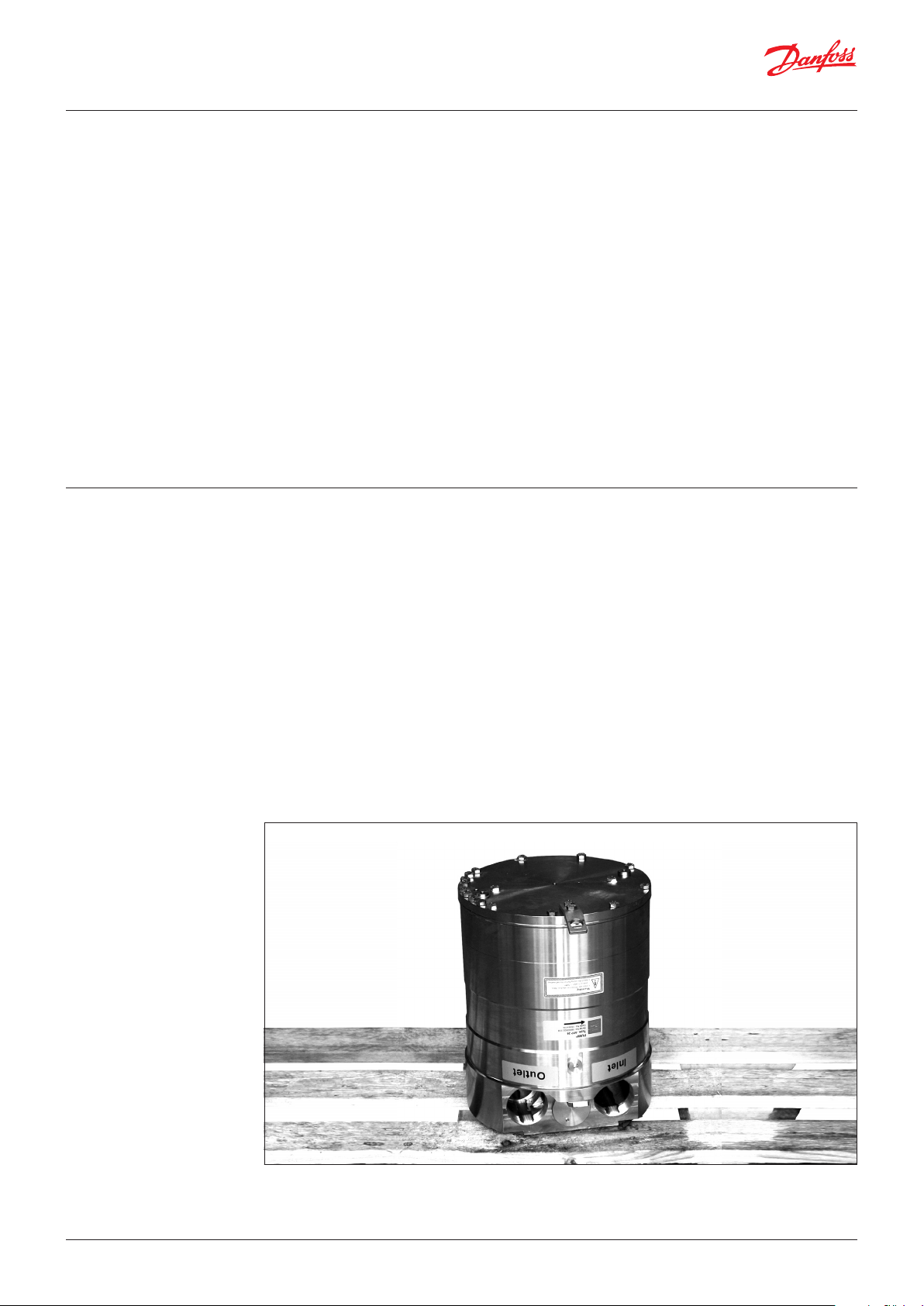
Place the pump on a pallet or other stable
surface above the ground. Ensure that the pump
cannot roll. It must be possible to place the pump
vertically with the shaft pointing downwards.
This can be done between two pallets or
between two boards on a pallet provided that
the distance is minimum 100 mm.
For a better understanding of the pump, please
see the exploded view on page 18, 19 and 20.
WARNING:
Do not reuse disassembled O-rings or shaft
seal as they might be damaged. Always use
new O-rings.
Important: It is essential that the pump is
serviced in conditions of absolute cleanliness.
© Danfoss | DCS (im) | 2017.062 | 180R9228 | 521B1181 | DKCFN.PI.013.V3.02
Page 3
Service guide | Disassembling and Assembling, APP 11-13 and APP 16-22
2. Disassembling the
pump
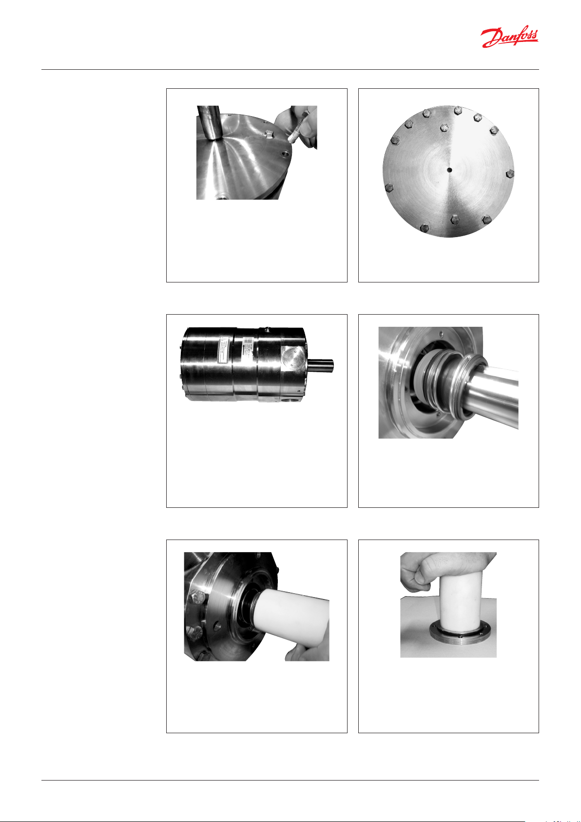
1. Disconnect the pump from the rest of the
system.
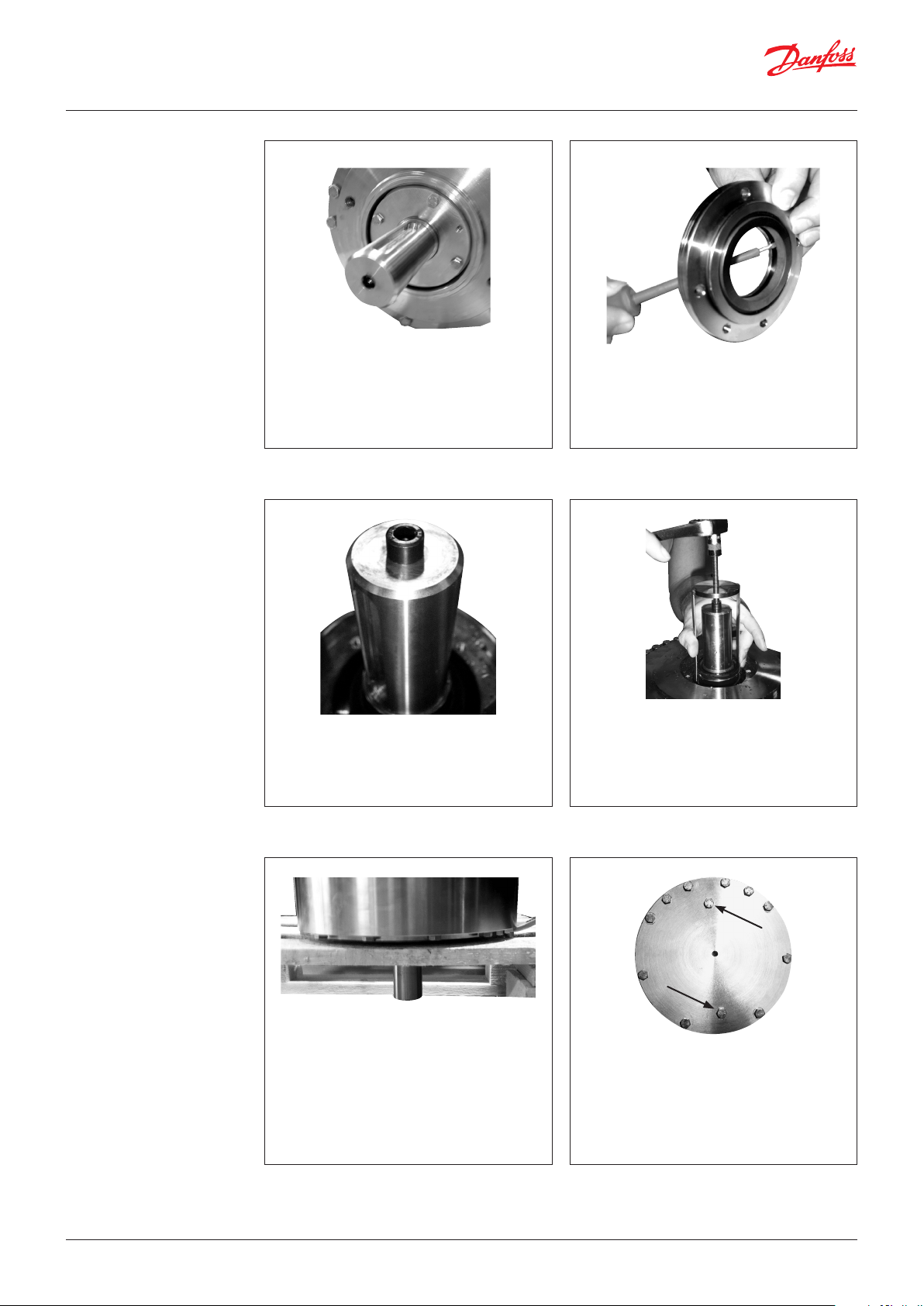
2. Using a 10 mm combination wrench,
unscrew the four bolts from shaft seal
flange.
If shaft seal flange is stuck, screw in two
bolts in holes in the flange to remove it.
3. Remove ceramic ring from flange by
carefully pushing it from the back of the
sealing ring.
4. Mount the M8 allen screw from the tool
set in the top of the shaft.
5. Wet the shaft and shaft seal with clean
filtered water.
7. Turn pump into vertical position with shaft
pointing downwards. Ensure minimum
100 mm (3,94 inch) free space for the shaft.
6. Carefully remove the shaft seal assembly
using the shaft seal extractor supplied in
the toolset. The extractor must fit
underneath the shaft seal. Press the arms
of the extractor together when turning the
bolt.
8. Using a 13 mm combination wrench,
remove all the bolts on the mounting
flange except the three shown in the next
picture.
WARNING:
Do not loosen the two screws keeping
swash plate in place.
© Danfoss | DCS (im) | 2017.06 180R9228 | 521B1181 | DKCFN.PI.013.V3.02 | 3
Page 4
Service guide | Disassembling and Assembling, APP 11-13 and APP 16-22
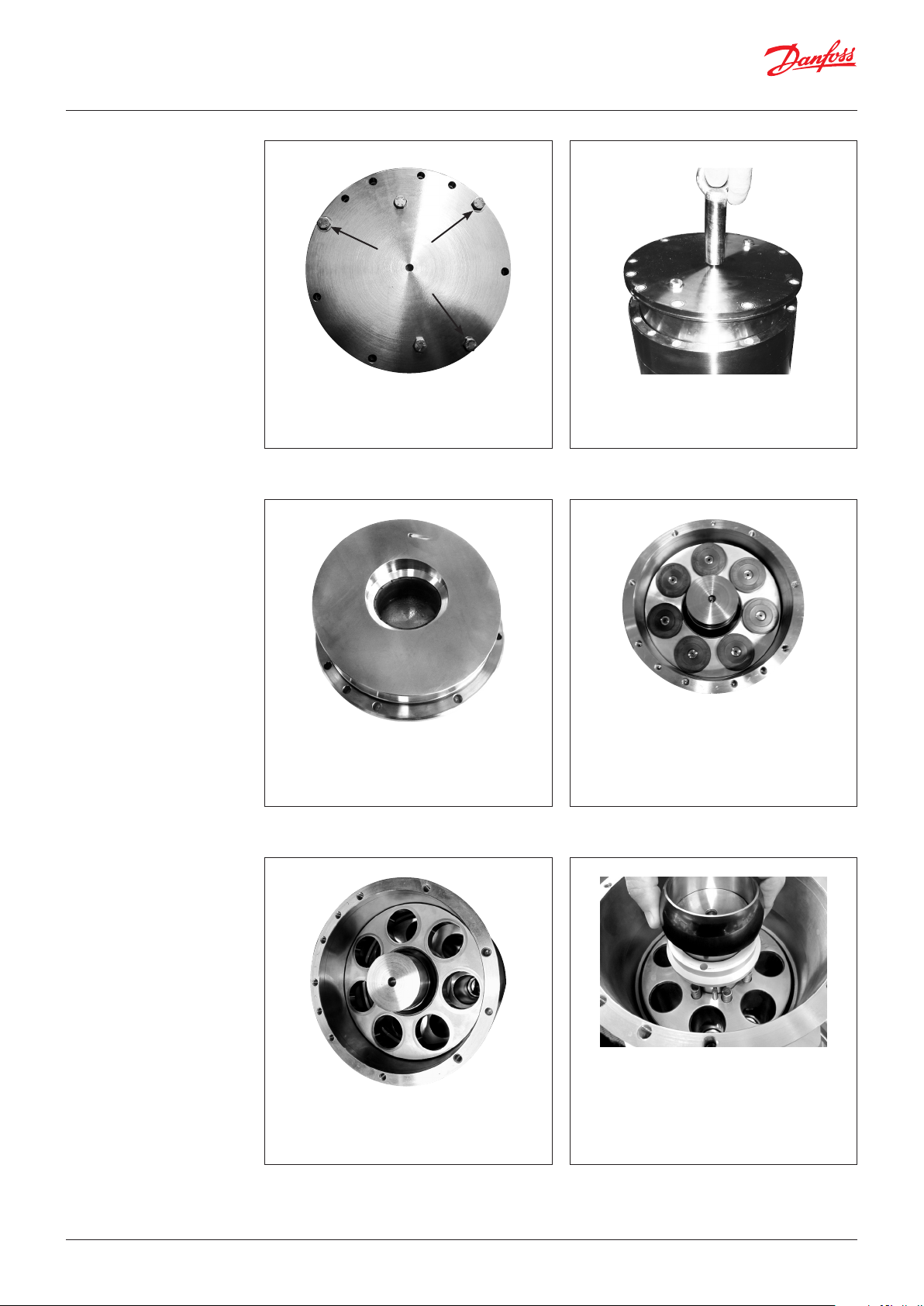
9. Unscrew the remaining three bolts. Turn
each bolt one round at the time to make
sure that the flange is removed as straight
forward as possible.
10. Screw the eye bolt in the M8 hole in the
middle of the flange. Pull it straight
upwards.
11. Swash plate must be placed so that its
surface is not scratched. For further
disassembling of swash plate, see page 11.
13. Remove the retainer plate and the retainer
ball.
Note: As the retainer ball is not attached
to the retainer plate, it might fall out.
12. Remove by hand the pistons one by one.
Be careful not to scratch the pistons. Tilt
the retainer plate to horizontal position for
easy removal of pistons, if required.
WARNING:
Do not use any tools.
14. Remove the retainer guide, the 4 springs
and the spring guide.
© Danfoss | DCS (im) | 2017.064 | 180R9228 | 521B1181 | DKCFN.PI.013.V3.02
Page 5
Service guide | Disassembling and Assembling, APP 11-13 and APP 16-22
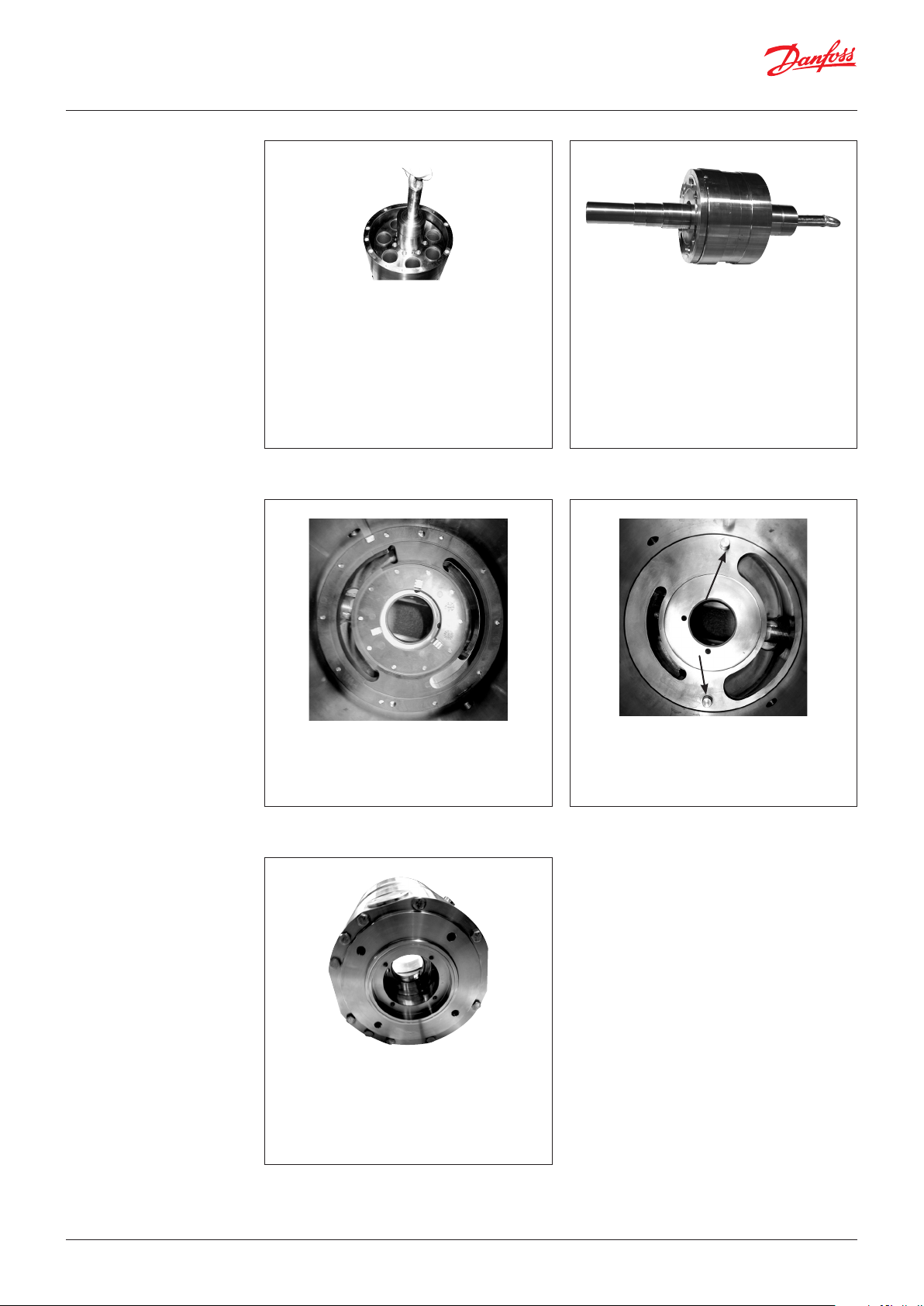
15. Mount a 8 mm eye bolt in the cylinder
barrel. Pull straight upwards. A continuous
lift will elevate the cylinder barrel out of
housing. This can only be done if shaft seal
is removed.
WARNING:
If the cylinder barrel is dropped or
lowered too fast into housing, the main
bearing/shaft bearing might be
damaged. It is not replaceable.
16. Place cylinder barrel upside down.
For further disassembling of cylinder
barrel and valve plate see page 12.
17. Remove the port plate by hand.
19. Place the pump horizontally.
20. Remove the remaining screws in port
flange by using a 13 mm combination
wrench. Carefully separate house and port
flange. Ensure that pin for the positioning
house is not lost.
18. Remove, by hand, the two pins.
Note: The following operation is only
necessary if O-ring on port flange is to
be changed.
21. For further disassembling of flush
valve, see page 12.
© Danfoss | DCS (im) | 2017.06 180R9228 | 521B1181 | DKCFN.PI.013.V3.02 | 5
Page 6
Service guide | Disassembling and Assembling, APP 11-13 and APP 16-22
3. Assembling the pump
WARNING:
Do not use silicone when assembling the
pump. Do not reuse disassembled O-rings;
they might be damaged. Always use new
O-rings.
Note:
Place the pump on a pallet or other stable
surface above the ground. Ensure that
the pump cannot roll. It must be possible
to place the pump vertically with the
shaft pointing downwards. This can be
done between two pallets or between
two boards on a pallet provided that the
distance is minimum 50 mm.
Important:
It is essential that the pump is serviced in
conditions of absolute cleanliness. All parts
must be absolute clean before mounting.
1. Lubrication:
• To prevent seizing-up, lubricate all
threads with PTFE lubrication type.
• O-rings inside pump may be lubricated
only with clean filtered water.
• O-rings for port flange, mounting flange
and flushing valve must be lubricated.
• It is important to lubricate ALL parts to
be assembled with clean filtered water
(Especially all PEEK parts).
3. Insert guide pin for positioning housing
on port flange. Ensure that two screw
holes can be reached from below.
2. Place port flange with O-ring pointing
upwards.
4. Mount the O-ring. Remember lubrication
of the O-ring with clean filtered water.
5. Position housing by aligning pin hole over
guide pin.
6. Gently press downwards. Be careful not to
squeeze the O-ring. If O-ring is damaged
the pump will leak.
© Danfoss | DCS (im) | 2017.066 | 180R9228 | 521B1181 | DKCFN.PI.013.V3.02
Page 7
Service guide | Disassembling and Assembling, APP 11-13 and APP 16-22
7. Screw in at least two screws from below.
8. Place housing horizontally. Screw in the
rest of the screws on port flange. Tighten
screws according to exploded view.
9. Place pump vertically. Place 10.5 mm pins
in port flange.
10. Position port plate by using the two pins.
Do not use force for this operation.
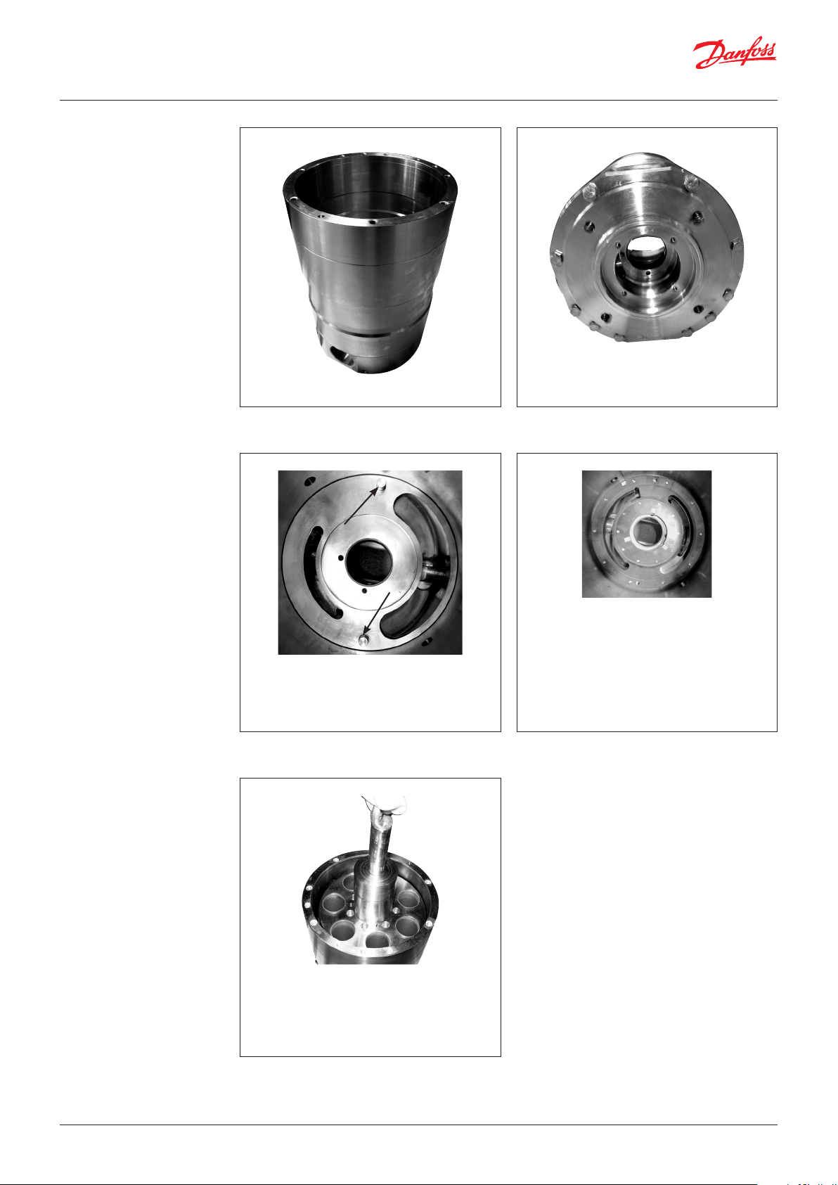
13. Make sure there is enough free space for
the shaft beneath the housing. Minimum
100 mm (3,94 inch). Carefully lower
cylinder barrel into housing.
11. Ensure port plate is fitted tightly against
the bottom.
IMPORTANT:
Lubricate port plate with clean filtered
fresh water.
If valve plate is disassembled from
cylinder barrel please see page 12
before continuing.
12. Screw eye bolt in cylinder barrel.
WARNING!
If cylinder barrel is dropped or lowered
too fast into housing, main bearing and
shaft bearing might be damaged.
Replacement can only be done at
Danfoss, Nordborg.
14. Unscrew M8 eye bolt.
© Danfoss | DCS (im) | 2017.06 180R9228 | 521B1181 | DKCFN.PI.013.V3.02 | 7
Page 8
Service guide | Disassembling and Assembling, APP 11-13 and APP 16-22
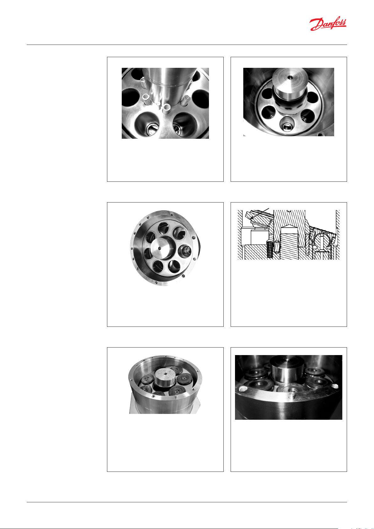
15. Place the 7 springs and 3 pins in cylinder
barrel. The pin holes are assymetric.
17. Place retainer plate in cylinder barrel.
Note:(Remember to lubricate the
retainer plate and cylinder bushings
with clean filtered water).
16. Place the spring guide and the retainer
guide on the cylinder shaft.
18. Ensure that retainer plate is oriented
correctly, i.e. with its slant surfaces
pointing downwards.
19. Place pistons in retainer plate and
cylinder barrel, When pistons are placed,
tilt retainer plate for easier placement of
swash plate.
If swash plate has been disassembled from
mounting flange, see page 11 for assembly
of swash plate.
20. Place the guide pin in the housing.
21. Lubricate piston shoes and swash plate
with clean filtered water.
22. Mount assembled swash plate, using the
guide pin.
© Danfoss | DCS (im) | 2017.068 | 180R9228 | 521B1181 | DKCFN.PI.013.V3.02
Page 9
Service guide | Disassembling and Assembling, APP 11-13 and APP 16-22
23. Place three bolts in mounting flange.
(Remember lubrication as stated in
paragraph 1 page 6.)
Turn each bolt one round at a time to
ensure mounting flange is mounted as
straight downwards as possible.
Be careful not to squeeze the O-ring.
24. Screw in the rest of the bolts and tighten all
screws according to exploded view.
25. Place pump horizontally to get access to
shaft.
26. Lubricate shaft with clean filtered water.
28. Use plastic press bush assembly tool
provided with large diameter pointing
towards seal, to press seal against
shoulder of stop for shaft seal.
27. Place stop for shaft seal and new shaft seal
on shaft.
WARNING: Ensure that carbon ring is
pointing outwards. Do not reuse the shaft
seal, due to risk of leakage.
29. Press new ceramic ring into shaft seal
flange, using plastic tool provided.
WARNING:
Ensure that the face with rubber seal is
positioned against shoulder in shaft
seal flange. Ensure that ceramic ring is
pointing outwards.
© Danfoss | DCS (im) | 2017.06 180R9228 | 521B1181 | DKCFN.PI.013.V3.02 | 9
Page 10

Service guide | Disassembling and Assembling, APP 11-13 and APP 16-22
30. Remove old O-ring and fit new one on
shaft seal flange.
32. Tighten the bolts with a torque according
to exploded view.
31. Place shaft seal flange on shaft.
© Danfoss | DCS (im) | 2017.0610 | 180R9228 | 521B1181 | DKCFN.PI.013.V3.02
Page 11

Service guide | Disassembling and Assembling, APP 11-13 and APP 16-22
4. Disassembling and
assembling of the
swash plate
WARNING:
Make sure that the surface on the swash
plate does not get any marks.
1. Place the swash plate upside down.
Remove the 2 bolts holding the swash
plate. Remove the mounting flange from
the swash plate.
O-rings
Guide pins
2. Check that the O-ring and pin are in good
condition (Provided with sealing set).
3. Change the O-ring on the mounting
flange.
5. Mount the assembled part on the
pump.
(Remember to lubricate the O-ring).
4. Mount the swash plate on the 2 pins.
Carefully by hand tilt the unit to
horizontal position and mount the 2 bolts
which hold the swash plate. Tighten the
bolts with a torque of 30 Nm +/-2 Nm.
Finally check the surface on the swash
plate for any marks or foreign particles.
© Danfoss | DCS (im) | 2017.06 180R9228 | 521B1181 | DKCFN.PI.013.V3.02 | 11
Page 12

Service guide | Disassembling and Assembling, APP 11-13 and APP 16-22
5. Disassembling and
assembling of cylinder
barrel and valve plate
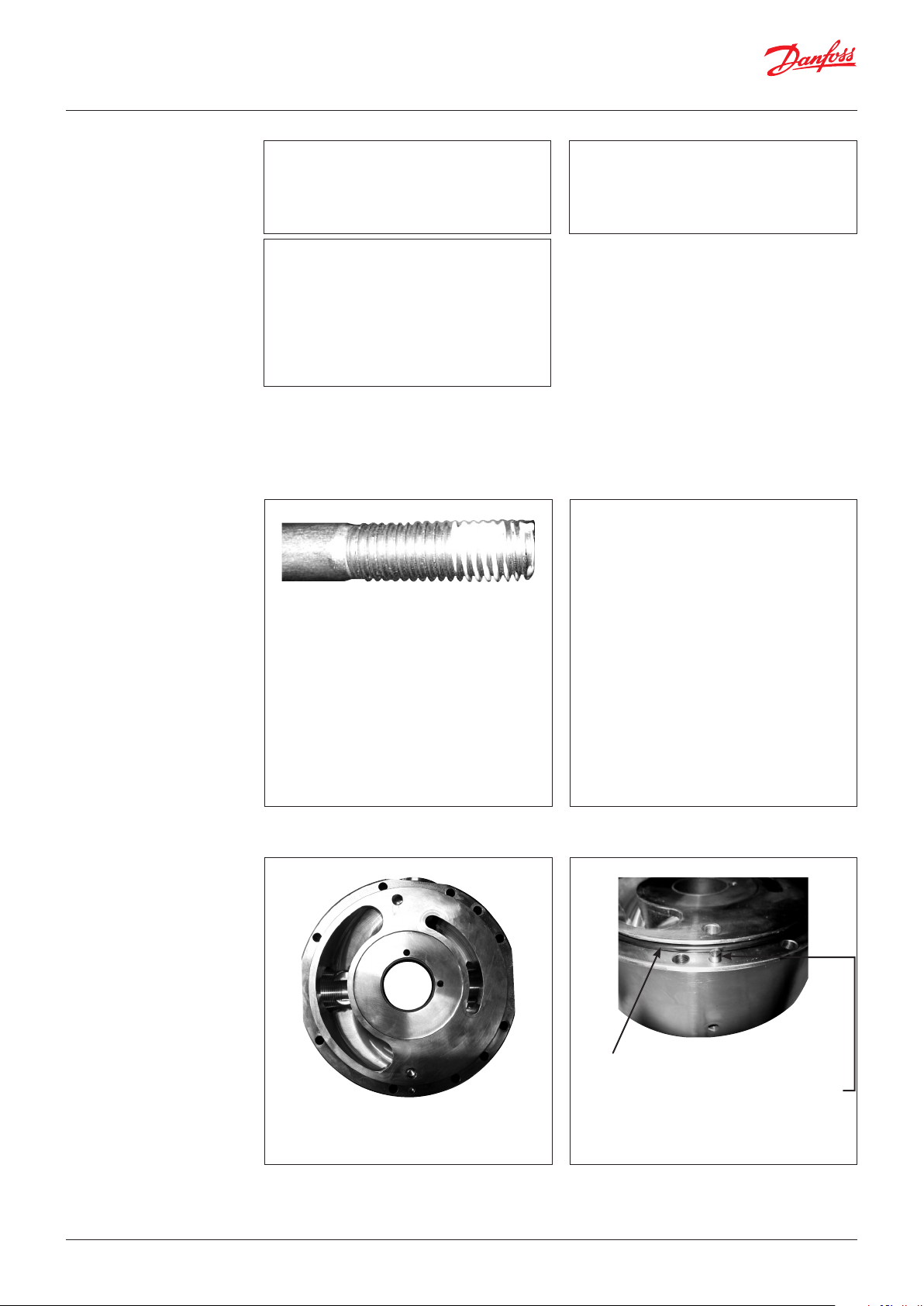
1. Push a screwdriver into the hole between
cylinder barrel and valve plate. Carefully
push downward the screwdriver so that it
makes a gap between cylinder barrel and
valve plate. Use this gap to put in another
screwdriver and loosen the valve plate
from the cylinder barrel.
Mount
backup
rings first
Mount then
O-rings
2. Remove the O-rings and backup rings. If
they have been removed they can not be
reused.
Mount the new back-up rings on the valve
plate first and then mount the O-rings.
6. Disassembling and
assembling of the
flush valve
3. Lubricate the new O-rings/back-up rings
and the liners in the cylinder barrel with
clean filtered water. Lower the valve plate
upside down on the cylinder barrel. Place
the press bush for valve plate (provided in
tool set) like on the picture. Screw the bolt
into the shaft of the cylinder barrel. Turn
the nut slowly clockwise. The valve plate
must slide carefully into the cylinder
barrel. Stop when the gap between
cylinder barrel and valve plate is 1-2 mm.
1. Unscrew the flush valve counter-clockwise
by using a pin wrench.
4. Remove the press bush again by screwing
the nut counter-clockwise.
Turn the nut slowly clockwise. The valve
plate must slide gently into the cylinder
barrel. Stop when the gap between
cylinder barrel and valve plate is 1–2 mm.
2. Remove the O-rings (green and black). If
necessary, change the valve cone, spring
and plug. If the spring is changed it is
important that it is located like on the
picture. The end of the spring must be
against the shoulder of the valve cone.
3. Put a little amount of grease on the thread
on the plug. Screw it into the port flange.
Tighten with a torque according to
exploded viewv.
© Danfoss | DCS (im) | 2017.0612 | 180R9228 | 521B1181 | DKCFN.PI.013.V3.02
Page 13

Service guide | Disassembling and Assembling, APP 11-13 and APP 16-22
7. Changing pistons
Tools needed are:
• 13 mm combination wrench
• 6 mm allen key
Service kit see parts list 521B0941
Note: It is essential that the pump is
serviced in conditions of absolute
cleanliness.
1. Disconnect the pump from the system, or
close all connection pipes (water supply).
Bleed water from the pump.
3. Unscrew the remaining 3 screws using
the combination wrench and turn each
screw a couple of rounds at the time, to
ensure the swash plate is loosened as
straight backwards as possible.
Note: There is nothing to hold the swash
plate!
Warning: Never unscrew the 2 screws
marked with coloured sealer.
2. Loosen all screws on the pump except the
3 screws as shown in the picture above,
using the 13 mm combination wrench.
4. Remove the flange/swash plate carefully.
© Danfoss | DCS (im) | 2017.06 180R9228 | 521B1181 | DKCFN.PI.013.V3.02 | 13
Page 14

Service guide | Disassembling and Assembling, APP 11-13 and APP 16-22
5. Place the swash plate upside down to
avoid scratches on the surface.
7. It is recommended to place the pistons
upside down on an even clean base/
surface.
Warning: Ensure that the piston shoes
and piston surfaces are not damaged or
scratched during removal.
6. Carefully remove the pistons one by one.
8. Remove the retainer plate.
9. Inspect the piston bushings in the cylinder
barrel for scratches or othe damages.
Small scratches are accepted if there are
no hard particles in the bushings.
If any worn pistons are found, all pistons must
be replaced. See page 17.
© Danfoss | DCS (im) | 2017.0614 | 180R9228 | 521B1181 | DKCFN.PI.013.V3.02
Page 15

Service guide | Disassembling and Assembling, APP 11-13 and APP 16-22
8. Assembling
Important: It is essential that the pump is
serviced in conditions of absolute
cleanliness.
All parts must be absolute clean before
mounting
1. Carefully push the retainer plate in place. 2. Ensure that the retainer plate is oriented
correctly with its slant surfaces pointing
downwards.
3. Insert all the pistons randomly.
© Danfoss | DCS (im) | 2017.06 180R9228 | 521B1181 | DKCFN.PI.013.V3.02 | 15
4. Tilt the retainer plate for easy insert of the
swash plate. Place the pin in the housing.
Page 16

Service guide | Disassembling and Assembling, APP 11-13 and APP 16-22
5. Replace the O-ring on mounting flange.
7. Mount the 3 screws as shown below. Turn
each screw a couple of rounds at the time,
to ensure the swash plate is pulled as
straight forward as possible.
Note: Be careful not to squeeze/damage
the O-ring.
6. Carefully insert the swash plate into the
housing.
8. Insert the remaining screws and cross
tighten them according to exploded view.
9. Connect the pump to the rest of the
system. Bleed the pump.
Follow the start-up procedures, see
instruction 180R9223.
© Danfoss | DCS (im) | 2017.0616 | 180R9228 | 521B1181 | DKCFN.PI.013.V3.02
Page 17

Service guide | Disassembling and Assembling, APP 11-13 and APP 16-22
9. When should the pistons
be replaced?
This section provides guides on how to determine whether the pistons of APP 11-13 and 16-22
are worn and should be replaced.
Note: If the pistons break down, the pump
will suffer a disastrous breakdown.
1. INo wear or cavitation of the piston shoe.
New inspection is required within 4,000
hours.
In case of doubt - the pistons must be replaced.
If any worn pistons are found, all pistons must be
replaced.
The pictures below are meant as guideline for
evaluating the wear of the sliding surface.W
2. Cavitation of the piston shoes.
New inspection is required within 2,000
hours.
3.. Cavitation of the piston shoes.
All pistons must be replaced within the
next 1,000 hours.
© Danfoss | DCS (im) | 2017.06 180R9228 | 521B1181 | DKCFN.PI.013.V3.02 | 17
Page 18

Service guide | Disassembling and Assembling, APP 11-13 and APP 16-22
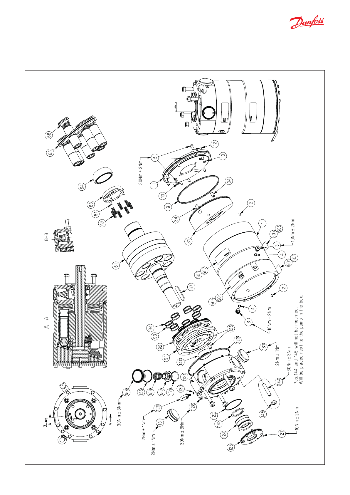
10. Exploded view
APP 11-13
lbf ft]
[22.13 lbf ft ± 2.21
[7.38 lbf ft ± 1.47 lbf ft]
[7.38 lbf ft ± 1.47 lbf ft]
[22.13 lbf ft ± 2.21 lbf ft]
[1.47 lbf ft ± 0.74 lbf ft]
[22.13 lbf ft
± 2.21 lbf ft]
[1.47 lbf
ft ± 0.74 lbf ft]
[22.13 lbf ft
± 2.21 lbf ft]
[1.47 lbf ft
± 0.74 lbf ft]
[7.38 lbf ft ± 1.47 lbf ft]
© Danfoss | DCS (im) | 2017.0618 | 180R9228 | 521B1181 | DKCFN.PI.013.V3.02
Page 19
Service guide | Disassembling and Assembling, APP 11-13 and APP 16-22
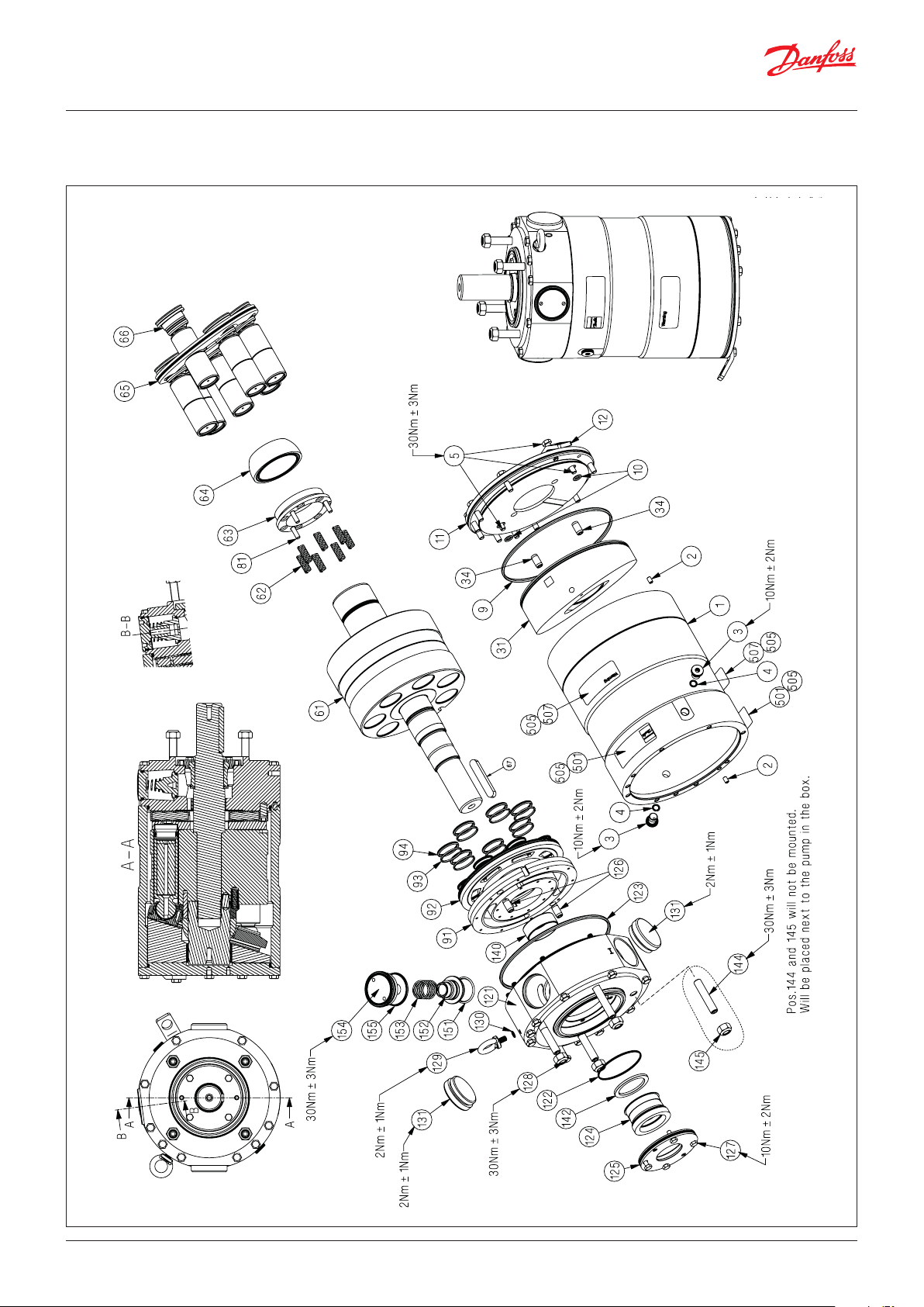
11. Exploded view
APP 16-19
[22.13 lbf ft ± 2.21 lbf ft]
[7.38 lbf ft ± 1.47 lbf ft]
± 1.47 lbf ft]
[7.38 lbf ft
[22.13 lbf ft ± 2.21 lbf ft]
[1.47 lbf ft
± 0.74 lbf ft]
[7.38 lbf ft ± 1.47 lbf ft]
[1.47 lbf ft
± 0.74 lbf ft]
[22.13 lbf ft ± 2.21 lbf ft]
[1.47 lbf ft
± 0.74 lbf ft]
[22.13 lbf ft
± 2.21 lbf ft]
© Danfoss | DCS (im) | 2017.06 180R9228 | 521B1181 | DKCFN.PI.013.V3.02 | 19
Page 20
Service guide | Disassembling and Assembling, APP 11-13 and APP 16-22
12. Exploded view
APP 22
[22.13 lbf ft ± 2.21 lbf ft]
[7.38 lbf ft ± 1.47 lbf ft]
[1.47 lbf ft
± 0.74 lbf ft]
[22.13 lbf ft ± 2.21 lbf ft]
± 1.47 lbf ft]
[7.38 lbf ft
[1.47 lbf ft
± 0.74 lbf ft]
[22.13 lbf ft ± 2.21 lbf ft]
[1.47 lbf ft
± 0.74 lbf ft]
[22.13 lbf ft
± 2.21 lbf ft]
[7.38 lbf ft ± 1.47 lbf ft]
© Danfoss | DCS (im) | 2017.0620 | 180R9228 | 521B1181 | DKCFN.PI.013.V3.02
Page 21

Service guide | Disassembling and Assembling, APP 11-13 and APP 16-22
© Danfoss | DCS (im) | 2017.06 180R9228 | 521B1181 | DKCFN.PI.013.V3.02 | 21
Page 22

Service guide | Disassembling and Assembling, APP 11-13 and APP 16-22
© Danfoss | DCS (im) | 2017.0622 | 180R9228 | 521B1181 | DKCFN.PI.013.V3.02
Page 23

Service guide | Disassembling and Assembling, APP 11-13 and APP 16-22
© Danfoss | DCS (im) | 2017.06 180R9228 | 521B1181 | DKCFN.PI.013.V3.02 | 23
Page 24
Danfoss A/S
High Pressure Pumps
DK-6430 Nordborg
Denmark
© Danfoss | DCS (im) | 2017.06
180R9228 | 521B1181 | DKCFN.PI.013.V3.02 | 24
 Loading...