


Data sheet
Data sheet
APP Pumps
APP 0.6-1.0 / APP 1.5-3.5 /
APP pumps
APP (W) 5.1-10.2 / APP 11-13 /
APP 0.6-1.0 / APP 1.5-3.5 / APP (W) 5.1-10.2 /
APP 16-22 / APP 21-46
APP 11-13 / APP 16-22 / APP 21-43
hpp.danfoss.com.
ro-solutions.com

Data sheet | APP 0.6-46 / APP (W) 5.1-10.2 pumps
Table of Contents
1. Introduction ............................................................................3
2. Benets.................................................................................3
3. Application examples ...................................................................3
4 Technical data ..........................................................................4
4.1 APP 0.6-1.0..............................................................................4
4.2 APP 1.5-3.5..............................................................................5
4.3 APP (W) 5.1-10.2 .........................................................................6
4.4 APP 11-13 ...............................................................................7
4.5 APP 16-22...............................................................................8
4.6 APP 21-30 ...............................................................................9
4.7 APP 38-46 .............................................................................10
5. Flow at dierent rpm...................................................................11
5.1 APP 0.6-1.0 ow curves measured at 80 barg ( 1160 psig ) ...............................11
5.2 APP 1.5-3.5 ow curves at 80 barg (1160 psig) ...........................................12
5.3 APP (W) 5.1-10.2 ow curves at 80 barg (1160 psig) ......................................13
5.4 APP 11-13 ow curves at 60 barg (870 psig) .............................................14
5.5 APP 16-22 ow curves at 60 barg (870 psig) .............................................15
5.6 APP 16-22 ow curves at 60 barg (870 psig) .............................................16
5.7 APP 21-30 ow curves at 60 barg (870 psig) .............................................17
5.8 APP 21-38 ow curves at 60 barg (870 psig) .............................................18
5.9 APP 46 ow curves 60 barg (870 psig) ..................................................19
6 Flushing valve curves ..................................................................20
6.1 APP 0.6–1.0 integrated ushing valve ..................................................20
6.2 APP 1.5–3.5 integrated ushing valve ...................................................20
6.3 APP 5.1-10.2 Flushing valve not available................................................21
6.4 APP 11-13 integrated ushing valve.....................................................21
6.5 APP 16–22 integrated ushing valve ....................................................21
6.6 APP 21–46 integrated ushing valve ...................................................22
7. Motor requirements....................................................................23
7.1 Calculation factor for APP 0.6-1.0 .......................................................23
7.2 Calculation factor for APP 1.5-3.5 .......................................................23
7.3 Calculation factor for APP (W) 5.1-10.2 ..................................................23
7.4 Calculation factor for APP 11-13.........................................................23
7.5 Calculation factor for APP 16-22 ........................................................23
7.6 Calculation factor for APP 21-46 ........................................................23
8. Temperature and corrosion.............................................................24
8.1 Temperature ...........................................................................24
9. Installation.............................................................................24
9.1 Filtration ...............................................................................25
9.2 RO system with direct supply: ..........................................................25
10. Dimensions and connections...........................................................27
10.1 APP 0.6-1.0.............................................................................27
10.2 APP 1.5-3.5.............................................................................28
10.3 APP (W) 5.1-10.2 ........................................................................29
10.4 APP 11-13 ..............................................................................30
10.5 APP 16-22..............................................................................31
10.6 APP 21-26 and APP 30/1500.............................................................32
10.7 APP 30/1200 and APP 38-46 ............................................................33
11. Dimensions with motor unit............................................................34
11.1 APP 0.6-3.5.............................................................................34
11.2 APP (W) 5.1-10.2 ........................................................................35
11.3 APP 11.0-13.0...........................................................................36
11.4 APP 16.0-22.0 ..........................................................................37
11.5 APP 21.0-38.0 ..........................................................................38
11.6 APP 46.................................................................................39
12. Accessories ............................................................................40
12.1 Accessories for APP (W) 5.1–10.2 ........................................................40
12.2 Accessories for APP 11–13 ..............................................................40
12.3 Accessories for APP 16–22 ..............................................................40
12.4 Accessories for APP 21–46 .............................................................40
13. Se rvice.................................................................................41
2
AI274333290009en-000701| 11.2021
Data sheet | APP 0.6-46 / APP (W) 5.1-10.2 pumps
1. Introduction
This data sheet is valid for APP pumps both non
ATEX and ATEX certied. ATEX certied pumps
are indicated by Ex in the type designation example APP 0.6 Ex.
The Danfoss range of APP high-pressure pumps
is designed according to EN 809 for use in RO
applications with low viscosity and corrosive
uids such as:
• Sea water
• Brackish water
• Waste water (APP W)
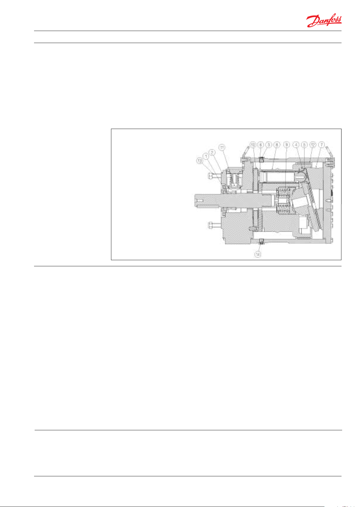
1: Shaft sealing
2: Port ange
3: Bleeding plug
4: Retainer plate
5: Piston/shoe
6: Valve plate
7: Swash plate
8: Cylinder barrel
9: Springs
10: Port plate
11: Flushing valve
(not available on
APP 5.1-10. 2)
12: Housing
13: Tail stock screws
14: Drain plug
Danfoss APP pumps are positive displacement
pumps with axial pistons that move a xed
amount of water in each cycle. Flow is proportional to the number of input shaft revolutions
(rpm). Unlike centrifugal pumps, they produce
the same ow at a given speed no matter what
the discharge pressure.
Below sectional drawing is an example of an
APP pump. The sectional drawing for the specic
pump sizes are to be found in the pump
instruction.
2. Benets
• Zero risk of lubricant contamination:
- Oil lubricants are replaced with the
pumped medium, water, so there is no
contamination risk from the pump.
• Low maintenance costs:
- Ecient design and all-stainless steel
construction ensure exceptionally long
life. When Danfoss specications are
met, service intervals of 8,000 hours can
be expected. Service is easy, and can be
carried out on-site due to the simple
design and few parts.
• Low energy costs:
- The highly ecient axial piston design
provides the lowest energy
consumption of any comparable pump
on the market.
• Easy installation:
- The most compact and lightest design
available.
- The pump can be installed vertically
and horizontally.
- No pulsation dampeners necessary due
to extremely low pressure pulsation.
3. Application examples Danfoss APP pumps are built into a broad range
of RO desalination plants around the world:
• Containerized solutions for hotels, resorts
and residences on islands and in coastal
regions
- Powered directly by electric motors or
combustion engines (with special
coupling).
- All pumps except APP (W) 5.1 - 10.2 are
supplied with an integrated ushing
valve that allows the uid to ow
from inlet to the outlet, when the pump
is not running.
• High reliability:
- All parts are made of high corrosion
resistant materials e.g. Duplex
(EN1.4462/ UNS S31803) and
Super Duplex (EN1.4410/UNS S32750)
stainless steel and carbon reinforced
PEEK.
• Certied quality:
- Pumps available as ATEX certied.
- For other certications, please see data
sheets for APP S (all super duplex) and
APP S 674 (API).
- Positive Material Identication (PMI)
report available on request.
- IATF 16949, ISO 9001, ISO 14001.
• Mobile systems for humanitarian and
military organizations
• Onboard systems for ships and yachts
• Oshore platforms for the oil and gas
industry
• Municipal and regional waterworks
AI274333290009en-000701 | 11.2021
3
Data sheet | APP 0.6-46 / APP (W) 5.1-10.2 pumps
4 Technical data
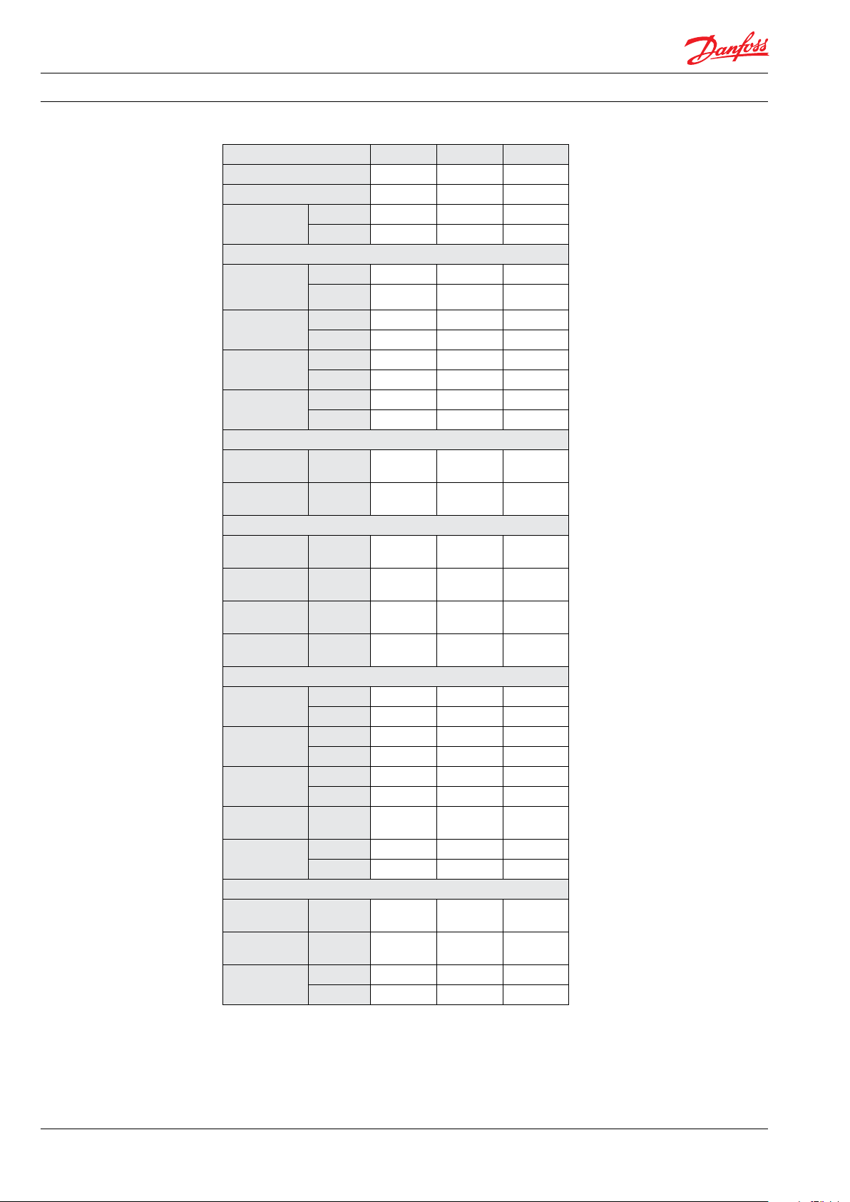
4.1 APP 0.6-1.0
Pump size APP 0.6 APP 0.8 APP 1.0
Code number APP 180B3048 180B3037 180B3049
Code number APP ATEX
Geometric
displacement
Pressure
Max. outlet
1)
pressure
continuous
Min. outlet
1)
pressure
2)
Inlet pressure
continuous
Max. inlet
pressure peak
Speed
Min. speed
continuous
Max. speed
2)
continuous
Typical ow - Flow curves available in item 5
1000 rpm at
max. pressure
1500 rpm at
max. pressure
1200 rpm at
max. pressure
1800 rpm at
max. pressure
Technical specications
3)
Media
temperature
Ambient
temperature
Weight (dry)
Sound pressure
level, LPA 1m
Footprint with
IEC motor
5)
6)
Typical motor size
Max. speed at
max. pressure
3000 rpm at
max. pressure
Torque at max.
outlet pressure
4)
180 B3148 180B3137 180B3149
cm³/rev. 4.07 5.08 6.30
in³/re v. 0.25 0.31 0.38
barg 83 83 83
psig 120 0 1200 12 00
barg 20 20 20
psig 290 290 290
barg 0.5 - 5 0.5 - 5 0.5 - 5
psig 7.3 - 72.5 7.3 - 72.5 7.3 - 72.5
barg 10 10 10
psig 145 145 145
rpm 700 700 700
rpm 3450 3450 3450
m³/ h 0.22 0.29 0.36
m³/ h 0.34 0.43 0.54
gpm 1.18 1.52 1.90
gpm 1.78 2.28 2.84
°C 2 - 50 2 - 50 2 - 50
°F 36 - 122 36 - 122 36 - 122
°C 0-50 0-50 0-50
°F 32 - 122 32 - 122 32 - 122
kg 5.2 5.2 5.2
11. 5 11.5 11.5
dB(A) 74 74 74
m² 0.1 0 .1 0.14
foot² 1.08 1.08 1. 51
kW 2.2 3.0 4.0
HP 3 5 5
Nm 5.8 7.2 8.9
lbf-ft 4.2 5.3 6.6
1)
For lower an d higher pressure , please contact D anfoss.
2)
For spee ds above 3000 rpm th e pump must be boos ted at a pressure
of 2-5 barg (29 - 72.5 psig).
3)
Depend ent on the NaCI conce ntration - see chap ter 8.
4)
Category 2, Zone 1 or Categor y 3, Zone 2.
4
AI274333290009en-000701| 11.2021
5)
A-weigh ted sound pressur e level at 1 m from the pum p unit
surfa ces (reference box) a cc. to EN ISO 20361 section 6 .2. The noise
measurem ents are perf ormed acc. to EN ISO 3744:2010 on a mot or-
pump unit at m ax. pressure and s peed.
6)
Max. area covered with recommended motor conguration
(excl. of spa ce to service pump)
Data sheet | APP 0.6-46 / APP (W) 5.1-10.2 pumps
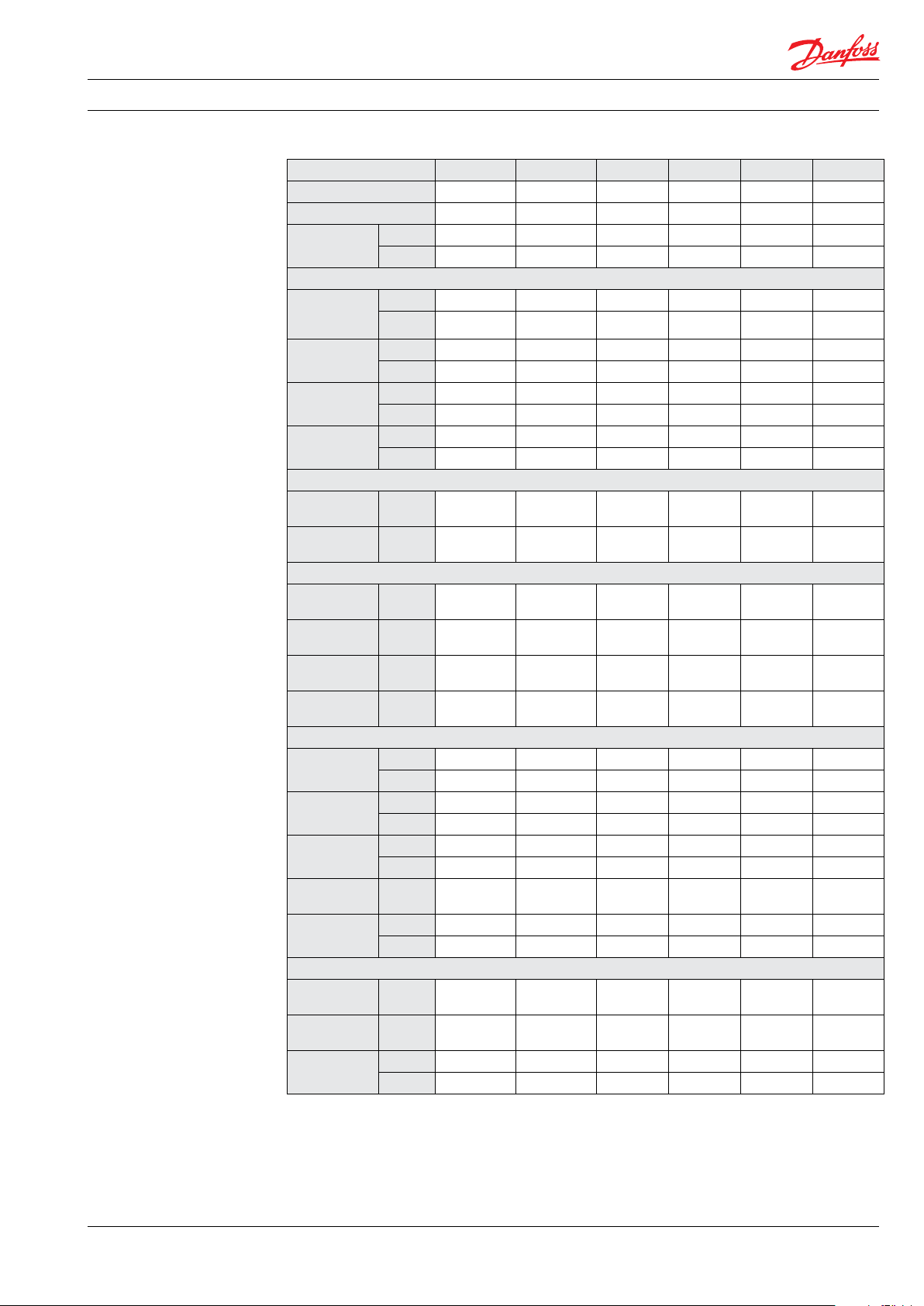
4.2 APP 1.5-3.5
Pump size APP 1.5 APP 1.8 APP 2.2 APP 2.5 APP 3.0 APP 3.5
Code number APP 180B30 43 180B3044 180B3045 180B3046 180B3030 180 B3032
Code number APP ATEX4)180 B3143 180B3144 18 0B3145 180B3146 18 0B3130 18 0B3132
Geometric
displacement
Pressure
Max. outlet
pressure
continuous
Min. outlet
pressure
Inlet pressure
continuous
Max. inlet
pressure peak
Speed
Min. speed
continuous
Max. speed
continuous
Typical ow - Flow curves available in item 5
1000 rpm at
max. pressure
1500 rpm at
max. pressure
1200 rpm at
max. pressure
1800 rpm at
max. pressure
Technical specications
3)
Media
temperature
Ambient
temperature
Weight (dry)
Sound
pressure level
Footprint with
IEC motor
Typical motor size
Max. speed at
max. pressure
3000 rpm at
max. pressure
Torque at max.
outlet pressure
cm³/rev.
in³/rev.
1)
barg 83 83 83 83 83 83
psig 120 0 1200 1200 120 0 1200 1200
1)
barg 20 20 20 20 20 20
psig 290 290 290 290 290 290
barg 0.5 - 5
psig 7.3 - 72.5
barg 10 10 10 10 10 10
psig 145 145 145 145 145 145
rpm 700 700 700 700 700 700
rpm 3450
m³/ h 0.53 0.57 0.73 0.90 1.02 1.19
m³/ h 0.79 0.86 1.09 1.34 1.54 1.79
gpm 2.80 3.03 3.83 4.73 5.41 6.30
gpm 4.19 4.55 5.75 7. 09 8.12 9.46
°C 2 - 50 2 - 50 2 - 50 2 - 50 2 - 50 2 - 50
°F 36 - 122 36 - 122 36 - 122 36 - 122 36 - 122 36 - 122
°C 0 - 50 0 - 50 0 - 50 0 - 50 0 - 50 0 - 50
°F 32 - 122 32 - 122 32 - 122 32 - 122 32 - 122 32 - 122
kg 8.6 8.6 8.6 8.6 8.6 8.6
lb 17 17 17 17 17 17
dB(A) 77 77 77 81 81 81
5)
m² 0.15 0.16 0.21 0.21 0.30 0.30
6)
foot² 1.61 1.72 2.26 2.26 3.23 3.23
kW 5.5 5.5 7.5 7.5 11 11
HP 7. 5 7.5 10.0 15.0 15. 0 15.0
Nm 13.0 13.9 17.4 21.3 24.5 28.7
lbf-ft 9.6 10. 3 12. 8 15.7 18.1 21. 2
9.31 10.04 12.52 15.35 17. 70 20.54
0.57 0.61 0.76 0.94 1.08 1.25
2)
2)
7.3 - 72.5 2)7.3 - 72.5
2)
0.5 - 5
3450
2)
2)
0.5 - 5
3450
2)
2)
2)
0.5 - 5 0.5 - 5
7.3 - 72.5 7.3 - 72.5
3000 3450
2)
2)
2)
0.5 - 5
7.3 - 72.5
3000
1)
For lower an d higher pressure , please contact D anfoss.
2)
For spee ds above 3000 rpm th e pump must be boos ted at a pressure
of 2-5 barg (29 - 72.5 psig).
3)
Depend ent on the NaCI conce ntration - see chap ter 8.
4)
Category 2, Zone 1 or Categor y 3, Zone 2.
AI274333290009en-000701 | 11.2021
5)
A-weigh ted sound pressur e level at 1 m from the pum p unit
surfa ces (reference box) a cc. to EN ISO 20361 section 6 .2. The noise
measurem ents are perf ormed acc. to EN ISO 3744:2010 on a mot or-
pump unit at m ax. pressure and s peed.
6)
Max. area covered with recommended motor conguration
(excl. of spa ce to service pump)
5

Data sheet | APP 0.6-46 / APP (W) 5.1-10.2 pumps
4.3 APP (W) 5.1-10.2
Pump size APP (W) 5.1 APP (W) 6.5 APP (W) 7.2 APP (W) 8.2 APP (W) 10.2
Code number APP 180B3005 180B3006 180 B3007 180B3008 180B3010
Code number APP ATEX
Code number APP W 180B3075 180B3076 180B3077 18 0B3078 180B3080
Geometric
displacement
Pressure
Max. outlet
pressure
continuous
Min. outlet
pressure
Inlet pressure
continuous
Max. inlet
pressure peak
Speed
Min. speed
continuous
Max. speed
continuous
Typical ow - Flow curves available in item 5
1000 rpm at max.
pressure
1500 rpm at max.
pressure
1200 rpm at max.
pressure
1800 rpm at max.
pressure
Technical specications
3)
Media
temperature
Ambient
temperature
Weight (dry)
Sound pressure
5)
level
Footprint with
IEC motor
6)
Typical motor size
Max. speed at
max. pressure
1200 rpm at max.
pressure
Torque at max.
outlet pressure
1)
For lower an d higher pressure , please contact D anfoss.
2)
For spee ds above 1500 rpm the pump m ust be boosted at a p ressure
of 2-5 barg (29 - 72.5 psig).
3)
Depend ent on the NaCI conce ntration - see chap ter 8.
4)
Category 2, Zone 1 or Categor y 3, Zone 2.
cm³/rev. 50.2 63.3 70. 3 80.4 100. 5
in³/re v. 3.06 3.86 4.29 4.91 6.13
1)
barg 83 83 83 83 83
psig 120 0 1200 120 0 120 0 120 0
1)
barg 20 20 20 20 20
psig 290 290 290 290 290
2)
barg 0.5 - 5 0.5 - 5 0.5 - 5 0.5 - 5 0.5 - 5
psig 7.3 - 72.5 7.3 - 72.5 7.3 - 72.5 7.3 - 72.5 7.3 - 72.5
barg 5 5 5 5 5
psig 72.5 72.5 72.5 72.5 72.5
rpm 700 700 700 700 700
2)
rpm 1800 1800 1800 1800 1800
m³/ h 2.79 3.57 4.01 4.62 5.83
m³/ h 4.19 5.36 6.01 6.93 8.75
gpm 14.75 18. 87 21.16 24.39 30.82
gpm 22.13 28.31 31.74 36.59 46.23
°C 2 - 50 2 - 50 2 - 50 2 - 50 2 - 50
°F 35.6 - 122 35.6 - 122 35.6 - 122 35.6 - 122 35.6 - 122
°C 0 - 50 0 - 50 0 - 50 0 - 50 0 - 50
°F 32 - 122 32 - 122 32 - 122 32 - 122 32 - 122
kg 30 30 30 30 30
lb 66 66 66 66 66
dB(A) 78 78 78 78 78
m² 0.32 0.33 0.33 0.35 0.43
foot² 3.44 3.55 3.55 3.77 4.63
kW 15.0 18 .5 22 22 30
HP 20 20 20 20 25
Nm 70 81 98 112 141
lbf-ft 52 65 73 83 10 4
4)
180B3105 180 B3106 180B3107 180B3108 18 0B 3110
5)
A- weighte d sound pressure l evel at 1 m from the pump u nit
surfa ces (reference box) a cc. to EN ISO 20361 section 6 .2. The noise
measurem ents are perf ormed acc. to EN ISO 3744:2010 on a mot or-
pump unit at m ax. pressure and s peed.
6)
Max. area covered with recommended motor conguration
(excl. of spa ce to service pump)
6
AI274333290009en-000701| 11.2021
Data sheet | APP 0.6-46 / APP (W) 5.1-10.2 pumps
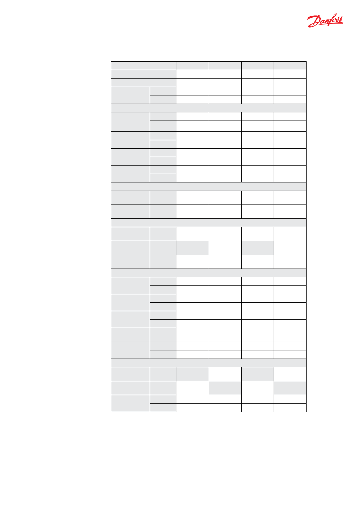
4.4 APP 11-13
Pump size AP P 11/1200 APP 11/150 0 APP 13/1200 APP 13/1500
Code number APP 18 0B3212 180B 3211 180 B3214 180B3213
Code number APP ATEX
Geometric
displacement
Pressure
Max. outlet
pressure
continuous
Min. outlet
pressure
Inlet pressure
continuous
Max. inlet
pressure. peak
Speed
Min. speed
continuous
Max. speed
continuous
Typical ow - Flow curves available in item 5
1000 rpm at
max. pressure
1500 rpm at
max. pressure
1200 rpm at
max. pressure
Technical specications
2)
Media
temperature
Ambient
temperature
Weight (dry)
Sound pressure
4)
level
Footprint with
IEC motor
5)
Typical motor size
Max. speed at
max. pressure
1200 rpm at
max. pressure
Torque at max.
outlet pressure
cm³/rev. 166.4 137. 4 197. 5 166.4
in³/re v. 10 .15 8.38 12 .05 10.15
1)
barg 83 70 83 70
psig 1200 1015 1200 1015
1)
barg 10 10 10 10
psig 145 145 145 145
barg 2 - 5 2 - 5 2 - 5 2 - 5
psig 29 - 72.5 29 - 72.5 29 - 72.5 29 - 72.5
barg 10 10 10 10
psig 145 145 145 145
rpm 700 700 700 700
rpm 1200 1500 1200 1500
m³/ h 9.22 7.50 11.0 7 9.23
m³/ h
gpm 48.71 39.61 58.51 48.75
°C 2 - 50 2 - 50 2 - 50 2 - 50
°F 35.6 - 122 35.6 - 122 35.6 - 122 35.6 - 122
°C 0 - 50 0 - 50 0 - 50 0 - 50
°F 32 - 122 32 - 122 32 - 122 32 - 122
kg 78 78 78 78
lb 172 172 172 172
dB(A) 85 85 85 85
m² 0.48 0.48 0.54 0.54
foot² 5.17 5 .17 5.81 5.81
kW 30.0 37. 0
HP 40.0 50.0
Nm 229 166 274 204
lbf-ft 169 123 202 150
3)
180B3222 180B3221 180B3224 180B3223
11. 25
13. 84
1)
For lower an d higher pressure , please contact D anfoss.
2)
Depend ent on the NaCI conce ntration - see chap ter 8.
4)
Category 2, Zone 1 or Categor y 3, Zone 2.
AI274333290009en-000701 | 11.2021
4)
A-weigh ted sound pressur e level at 1 m from the pum p unit
surfa ces (reference box) a cc. to EN ISO 20361 section 6 .2. The noise
measurem ents are perf ormed acc. to EN ISO 3744:2010 on a mot or-
pump unit at m ax. pressure and s peed.
5)
Max. area covered with recommended motor conguration
(excl. of spa ce to service pump)
7
Data sheet | APP 0.6-46 / APP (W) 5.1-10.2 pumps
4.5 APP 16-22
Pump size APP 16/1200 APP 16/1500 APP 17/120 0 APP 17/1500 A PP 19/120 0 APP 19/1500 APP 22/1200 APP 22/1500
Code number APP 18 0B325 4 180B3250 180B3255 180B3251 180B3256 180B3252 180B3257 180B3253
Code number APP ATEX3)180B326 4 180B3260 180B3265 180B3261 180B3266 180B3262 180B3267 180B3263
Geometric
displacement
Pressure
Max. outlet
pressure
continuous
Min. outlet
pressure
Inlet pressure
continuous
Max. inlet
pressure peak
Speed
Min. speed
continuous
Max. speed
continuous
Typical ow - Flow curves available in item 5
1000 rpm at
max. pressure
1500 rpm at
max. pressure
1200 rpm at
max. pressure
Technical specications
2)
Media
temperature
Ambient
temperature
Weight (dry)
Sound pressure
4)
level
Footprint with
IEc motor
Typical motor size
Max. speed at
max. pressure
1200 rpm at
max. pressure
Torque at max.
outlet pressure
cm³/rev. 234.6 188.3 253.3 19 7.5 272.3 219.7 310.6 253.3
in³/re v. 14.32 11.49 15.46 12 .05 16.62 13.41 18.95 15.46
1)
barg 83 70 83 70 83 70 83 70
psig 12 00 1015 1200 1015 1200 1015 1200 1015
1)
barg 10 10 10 10 10 10 10 10
psig 145 145 145 145 145 145 145 145
barg 2 - 5 2 - 5 2 - 5 2 - 5 2 - 5 2 - 5 2 - 5 2 - 5
psig 29 - 72.5 29 - 72.5 29 - 72.5 29 - 72.5 29 - 72.5 29 - 72.5 29 - 72.5 29 - 72.5
barg 10 10 10 10 10 10 10 10
psig 145 145 145 145 145 145 145 145
rpm 700 700 700 700 700 700 700 700
rpm 120 0 1500 120 0 1500 1200 150 0 1200 1500
m³/ h 13.38 10.67 14.57 11. 25 15.71 12 .55 18.06 14 .61
m³/ h 16.01 16.88 18 .82 21.92
gpm 70.70 56.40 76.98 59.44 82.98 66.30 95.43 7 7.21
°C 2 - 50 2 - 50 2 - 50 2 - 50 2 - 50 2 - 50 2 - 50 2 - 50
°F 35.6 - 122 35.6 - 122 35.6 - 122 35.6 - 122 35.6 - 122 35.6 - 122 35.6 - 122 35.6 - 122
°C 0 - 50 0 - 50 0 - 50 0 - 50 0 - 50 0 - 50 0 - 50 0 - 50
°F 32 - 122 32 - 122 32 - 122 32 - 122 32 - 122 32 - 122 32 - 122 32 - 122
kg 78 78 78 78 78 78 78 78
lb 17 2 17 2 17 2 172 172 172 172 172
dB(A) 84 84 84 84 84 84 84 84
m² 0.54 0.58 0.59 0.59 0.76 0.76 0.80 0.80
5)
foot² 5.81 6.26 6.35 6.35 8.18 8.18 8.61 8 .61
kW 37. 0 37. 0 45.0 55.0
HP 60.0 60.0 75.0 75.0
Nm 316 223 343 234 372 263 426 305
lbf-ft 233 165 253 173 275 194 314 225
1)
For lower an d higher pressure , please contact D anfoss.
2)
Depend ent on the NaCI conce ntration - see chap ter 8.
4)
Category 2, Zone 1 or Categor y 3, Zone 2.
4)
A-weigh ted sound pressur e level at 1 m from the pum p unit
surfa ces (reference box) a cc. to EN ISO 20361 section 6 .2. The noise
measurem ents are perf ormed acc. to EN ISO 3744:2010 on a mot or-
pump unit at m ax. pressure and s peed.
5)
Max. area covered with recommended motor conguration
(excl. of spa ce to service pump)
8
AI274333290009en-000701| 11.2021
Data sheet | APP 0.6-46 / APP (W) 5.1-10.2 pumps
4.6 APP 21-30
Pump size APP 21/120 0 APP 21/1500 APP 24/1200 APP 24/1500 APP 26/1200 APP 26/1500 APP 30/12 00 APP 30/1500
Code number APP 180B3051 180B3052 180B3054 180B3055 180B3056 180 B3057 180B3060 180B3062
Code number APP ATEX3)180B3151 On request 180B3154 180B3155 On request On request On request On request
Geometric
displacement
Pressure
Max. outlet
pressure
continuous
Min. outlet
pressure
Inlet pressure
continuous
Max. inlet
pressure peak
Speed
Min. speed
continuous
Max. speed
continuous
Typical ow - Flow curves available in item 5
1000 rpm at
max. pressure
1500 rpm at
max. pressure
1200 rpm at
max. pressure
Technical specications
2)
Media
temperature
Ambient
temperature
Weight (dry)
Sound pressure
4)
level
Footprint with
IEC motor
Typical motor size
Max. speed at
max. pressure
1200 rpm at
max. pressure
Torque at max.
outlet pressure
cm³/rev. 308.5 256 362 282 389 308.5 444 362
in³/re v. 18. 83 15.62 22.09 17. 21 23.74 18. 83 2 7.09 22.09
1)
barg 83 83 83 83 83 83 83 83
psig 1200 1200 120 0 1200 1200 120 0 1200 120 0
1)
barg 10 10 10 10 10 10 10 10
psig 145 145 145 145 145 145 145 145
barg 2 - 5 2 - 5 2 - 5 2 - 5 2 - 5 2 - 5 2 - 5 2 - 5
psig 29 - 72.5 29 - 72.5 29 - 72.5 29 - 72.5 29 - 72.5 29 - 72.5 29 - 72.5 29 - 72.5
barg 10 10 10 10 10 10 10 10
psig 145 145 145 145 145 145 145 145
rpm 700 700 700 700 700 700 700 700
rpm 12 00 1500 12 00 1500 1200 1500 120 0 1500
m³/ h 17. 80 14.80 21.02 16 .36 22.47 17.8 6 26.05 21.12
m³/ h 22.20 24.54 26.79 31. 69
gpm 94.07 78.18 111. 03 86.43 118.71 94.37 137. 64 111. 60
°C 2 - 50 2 - 50 2 - 50 2 - 50 2 - 50 2 - 50 2 - 50 2 - 50
°F 35.6 - 122 35.6 - 122 35.6 - 122 35.6 - 122 35.6 - 122 35.6 - 122 35.6 - 122 35.6 - 122
°C 0 - 50 0 - 50 0 - 50 0 - 50 0 - 50 0 - 50 0 - 50 0 - 50
°F 32 - 122 32 - 122 32 - 122 32 - 122 32 - 122 32 - 122 32 - 122 32 - 122
kg 105 105 105 105 105 105 105 105
lb 231 231 231 231 231 231 231 231
dB(A) 85 85 85 85 85 85 85 85
m² 0.76 0.76 0.80 0.80 0.83 0.83 0.83 0.83
5)
foot² 8.18 8.18 8.61 8.61 8.93 8.93 8.93 8.93
kW 55.0 75.0 55.0 75.0 75.0 75.0 90.0 90.0
HP 75.0 100.0 100.0 12 5.0
Nm 418 355 490 388 527 426 608 498.68
lbf-ft 308 262 361 286 389 314 449 36 7.81
1)
For lower an d higher pressure , please contact D anfoss.
2)
Depend ent on the NaCI conce ntration - see chap ter 8.
4)
Category 2, Zone 1 or Categor y 3, Zone 2.
4)
A-weigh ted sound pressur e level at 1 m from the pum p unit
surfa ces (reference box) a cc. to EN ISO 20361 section 6 .2. The noise
measurem ents are perf ormed acc. to EN ISO 3744:2010 on a mot or-
pump unit at m ax. pressure and s peed.
5)
Max. area covered with recommended motor conguration
(excl. of spa ce to service pump)
AI274333290009en-000701 | 11.2021
9
Data sheet | APP 0.6-46 / APP (W) 5.1-10.2 pumps
4.7 APP 38-46
Pump size APP 38/1500 APP 46/1780
Code number APP 180B3071 180B3072
Code number APP ATEX
Geometric
displacement
Pressure
Max. outlet
pressure
continuous
Min. outlet
pressure
Inlet pressure
continuous
Max. inlet
pressure. peak
Speed
Min. speed
continuous
Max. speed
continuous
Typical ow - Flow curves available in item 5
1000 rpm at
max. pressure
1500 rpm at
max. pressure
1200 rpm at
max. pressure
Technical specications
2)
Media
temperature
Ambient
temperature
Weight (dry)
Sound
pressure
4)
level
Footprint with
IEC motor
Typical motor size
Max. speed at
max. pressure
Torque at
max. outlet
pressure
cm³/rev. 444 444
in³/re v. 27. 09 2 7.09
1)
barg 83 70
psig 120 0 1015
1)
barg 10 10
psig 145 145
barg 2 - 5 2.5/3.5- 5
6)
psig 29 - 72.5 36.5/50.8 - 72.5
barg 10 10
psig 145 145
rpm 700 700
rpm 150 0 1700/1780
6)
m³/ h 26.20 26.29
m³/ h 39.30 39.44
gpm 138 .41 138.91
°C 2 - 50 2 - 50
°F 35.6 - 122 35.6 - 122
°C 0-50 0-50
°F 32 - 122 32 - 122
kg 105 105
lb 231 231
dB(A) 85 85.3
m² 0.83 1.10
5)
foot² 8.93 11.8 4
kW 110 .0 11 0.0
Nm 617 546
lbf-ft 455 402
3)
On request Not available
1)
For lower an d higher pressure , please contact D anfoss.
2)
Depend ent on the NaCI conce ntration - see chap ter 8.
4)
Category 2, Zone 1 or Categor y 3, Zone 2.
10
AI274333290009en-000701| 11.2021
4)
A-weigh ted sound pressur e level at 1 m from the pum p unit
surfa ces (reference box) a cc. to EN ISO 20361 section 6 .2. The noise
measurem ents are perf ormed acc. to EN ISO 3744:2010 on a mot or-
pump unit at m ax. pressure and s peed.
5)
Max. area covered with recommended motor conguration
(excl. of spa ce to service pump)
6)
For oper ation at speed be low 170 0 RPM , min. pressure ca n be
reduced t o 2.5 barg
Data sheet | APP 0.6-46 / APP (W) 5.1-10.2 pumps
APP 0.6
APP 0.8
APP 1.0
gpm
1.3
1.2
1.1
0.9
0.8
0.7
0.6
1.0
1.4
0.4
0
0.1
0.2
0.3
0.5
1300
1500
1100
1900
2100
1700
2500
2700
2300
3100
3300
3450
2900
900
700
rpm
m
3
/h
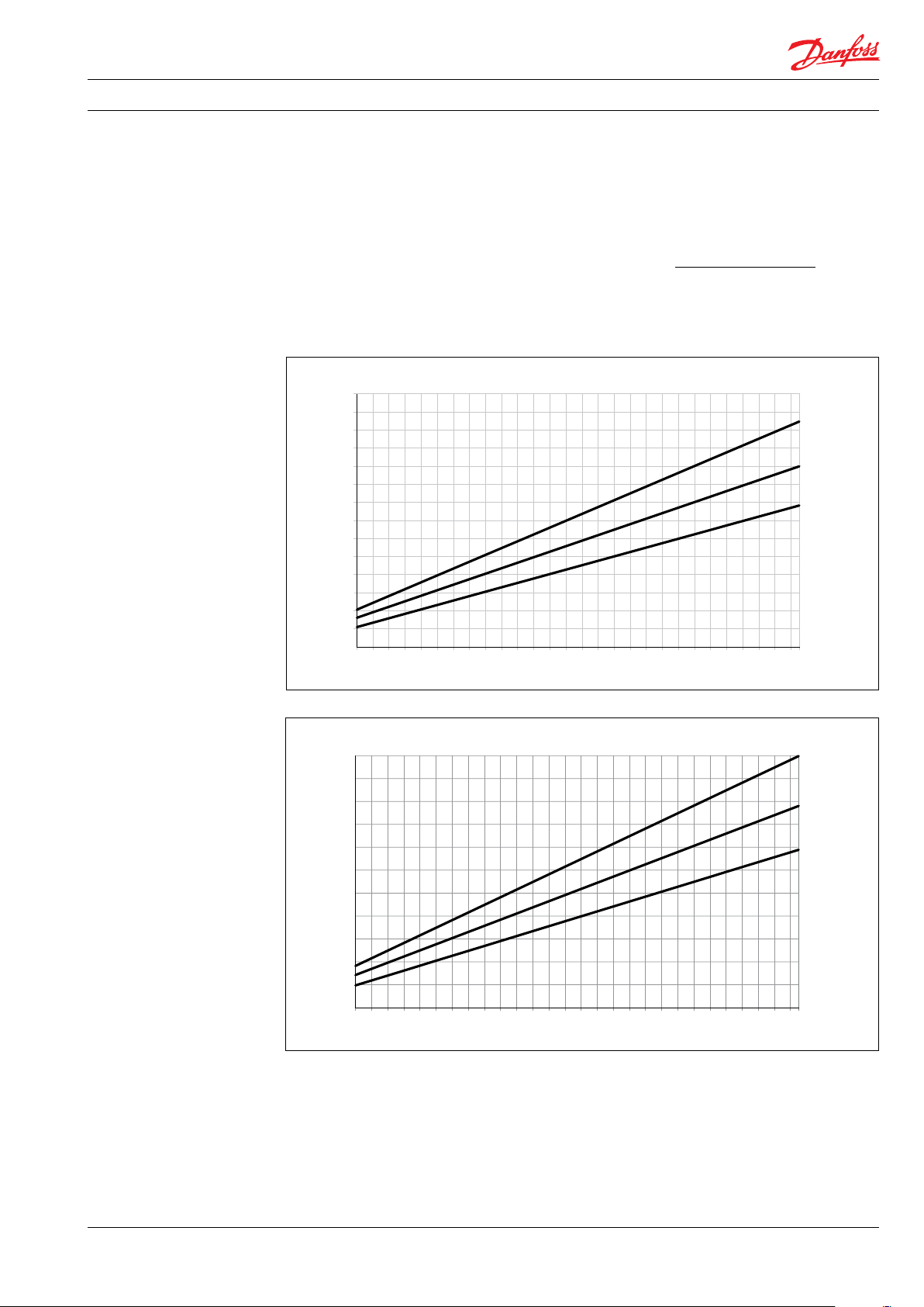
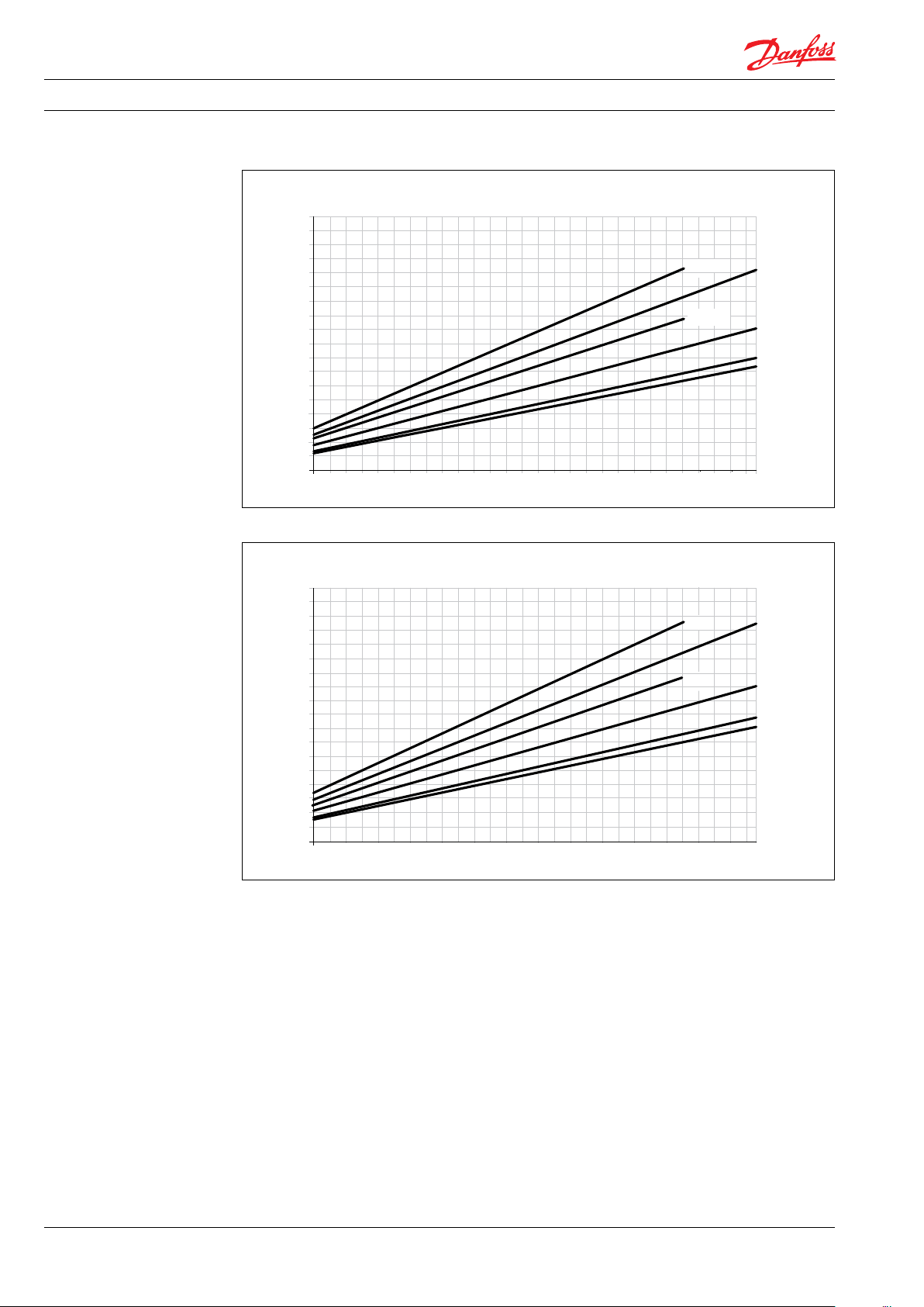
5. Flow at dierent rpm
If the ow required and the rotation speed (rpm) of the
pump is known, it is easy to select the pump tting the
application best by using the diagrams below.
Furthermore, these diagrams shows that the
ow can be changed by changing the rotation
speed of the pump. The ow/rpm ratio is
constant, and the “required” ow can be
obtained by changing the rotation speed to a
corresponding value. Thus, the required rpm
can be determined as:
Required ow x Rated rpm
Required rpm =
Rated ow
5.1 APP 0.6-1.0 ow curves measured at 80 barg ( 1160 psig )
3
m
/h
1.4
1.3
1.2
1.1
1.0
0.9
0.8
0.7
0.6
0.5
0.4
0.3
0.2
0.1
0
5.5
5.0
4.5
4.0
3.5
3.0
2.5
2.0
1.5
1.0
0.5
700
0
700
900
900
1100
1100
1300
1300
1500
1500
1700
1700
1900
1900
2100
2100
2300
2300
2500
2500
2700
2700
2900
2900
3100
3100
3300
3300
APP 1.0
APP 0.8
APP 0.6
rpm
3450
APP 1.0
APP 0.8
APP 0.6
rpm
3400
AI274333290009en-000701 | 11.2021
11
Data sheet | APP 0.6-46 / APP (W) 5.1-10.2 pumps
APP 1.5
APP 1.8
APP 2.2
APP 2.5
APP 3.0
APP 3.5
rpm
4.5
4.0
3.5
3.0
2.5
2.0
1.5
1.0
0
0.5
1300
1500
1100
1900
2100
1700
2500
2700
2300
3100
3300
3450
2900
900
700
m3/h
5.2 APP 1.5-3.5 ow curves at 80 barg (1160 psig)
m3/h
4.5
4.0
3.5
3.0
2.5
2.0
1.5
1.0
0.5
0
700
900
1100
1300
1500
1700
1900
2100
2300
2500
2700
2900
APP 3.5
APP 2.5
3100
3300
3450
APP 3.0
APP 2.2
APP 1.8
APP 1.5
rpm
gpm
18.0
16.0
14.0
12.0
10.0
1300
1500
1700
8.0
6.0
4.0
2.0
0
700
900
1100
1900
2100
2300
2500
2700
2900
APP 3.5
APP 2.5
3100
3300
3450
APP 3.0
APP 2.2
APP 1.8
APP 1.5
rpm
12
AI274333290009en-000701| 11.2021
Data sheet | APP 0.6-46 / APP (W) 5.1-10.2 pumps
1000
1200
1300
1100
1500
1600
1400
1800
1700
800
900
700
APP (W )10.2
APP (W) 8.2
APP (W) 7.2
APP (W) 6.5
APP (W) 5.1
rpm
m
3
/h
2.0
3.0
4.0
5.0
6.0
7.0
8.0
9.0
10.0
11.0
1.0
0
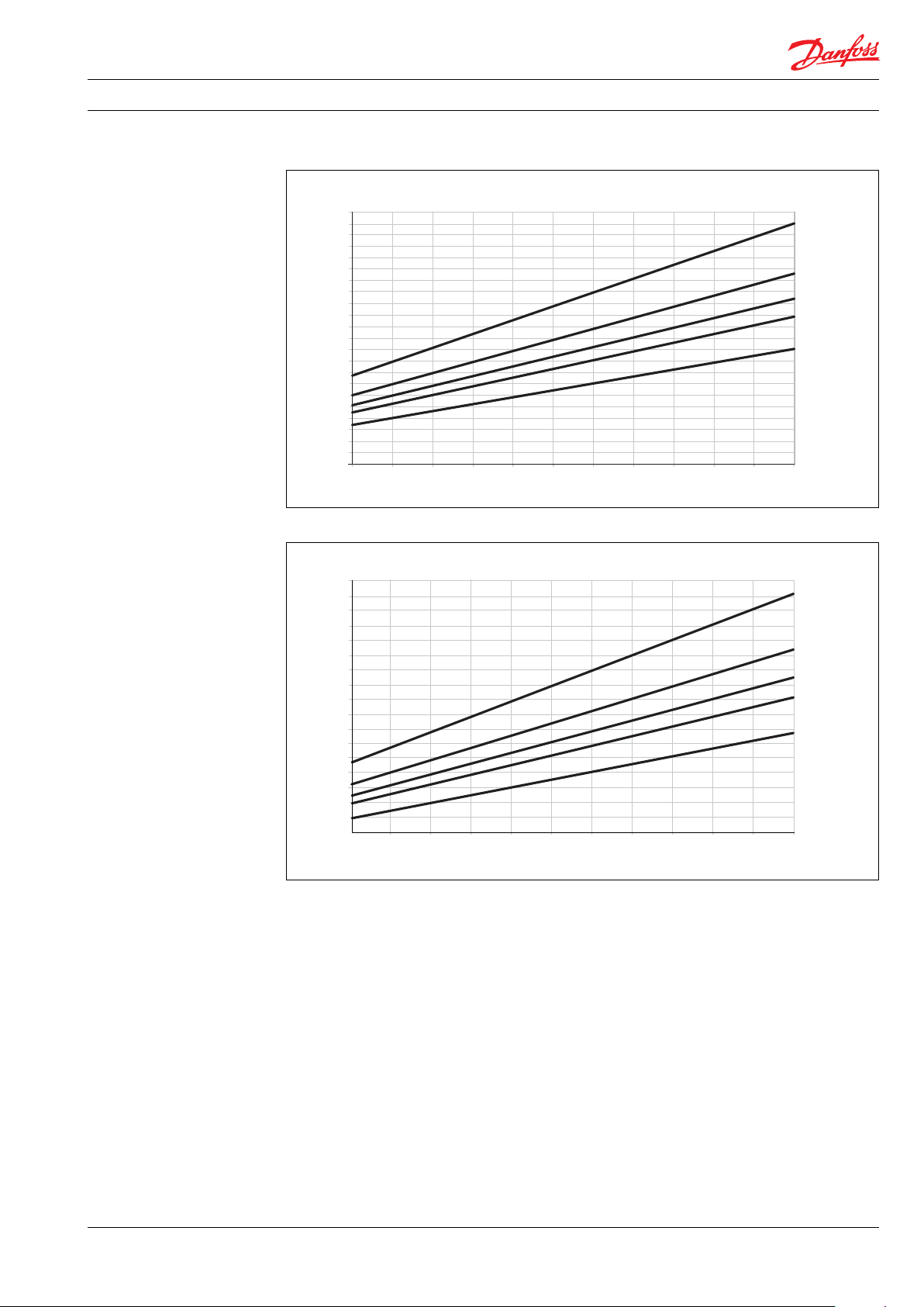
5.3 APP (W) 5.1-10.2 ow curves at 80 barg (1160 psig)
3
m
/h
11.0
10.0
9.0
8.0
7.0
6.0
5.0
4.0
3.0
2.0
1.0
0
700
800
900
1000
1100
1200
1300
1400
1500
1600
1700
APP (W )10.2
APP (W) 8.2
APP (W) 7.2
APP (W) 6.5
APP (W) 5.1
rpm
1800
gpm
45.0
APP (W) 10.2
40.0
35.0
30.0
APP (W) 8.2
APP (W) 7.2
APP (W) 6.5
25.0
20.0
APP (W) 5.1
15.0
10.0
5.0
700
800
900
1000
1100
1200
1300
1400
1500
1600
1700
rpm
1800
AI274333290009en-000701 | 11.2021
13

Data sheet | APP 0.6-46 / APP (W) 5.1-10.2 pumps
4.0
5.0
6.0
7.0
8.0
9.0
10.0
11.0
12.0
13.0
14.0
15.0
4.0
5.0
6.0
7.0
8.0
9.0
10.0
11.0
12.0
13.0
14.0
15.0
1200
1300
1400
1500
1100
1000
900
800
700
APP 11/1500
APP 13/1500
APP 13/1200
APP 11/1200
rpm
m
3
/h
5.4 APP 11-13 ow curves at 60 barg (870 psig)
3
/h
m
APP 13/1200
APP 11/1200
APP 13/1500
APP 11/1500
rpm
700
800
900
1000
1100
1200
1300
1400
1500
gpm
65.0
60.0
55.0
50.0
45.0
APP 11/1200
APP 13/1200
APP 13/1500
APP 11/1500
40.0
35.0
30.0
25.0
20.0
700
800
900
1000
1100
1200
1300
1400
rpm
1500
14
AI274333290009en-000701| 11.2021

Data sheet | APP 0.6-46 / APP (W) 5.1-10.2 pumps
800
900
1000
1100
1200
700
rpm
m
3
/h
6.0
8.0
10.0
12.0
14.0
16.0
18.0
20.0
22.0
APP 22/1200
APP 19/1200
APP 17/1200
APP 16/1200
5.5 APP 16-22 ow curves at 60 barg (870 psig)
3
/h
m
22.0
20.0
18.0
16.0
14.0
12.0
10.0
8.0
APP 22/1200
APP 19/1200
APP 17/1200
APP 16/1200
6.0
700
800
900
1000
1100
rpm
1200
gpm
APP 22/1200
90.0
80.0
APP 19/1200
APP 17/1200
70.0
APP 16/1200
60.0
50.0
40.0
30.0
700
800
900
1000
1100
rpm
1200
AI274333290009en-000701 | 11.2021
15

Data sheet | APP 0.6-46 / APP (W) 5.1-10.2 pumps
1000
1200
1300
1100
1500
1400
800
900
700
APP 22/1500
APP 19/1500
APP 17/1500
APP 16/1500
rpm
6.0
8.0
10.0
12.0
14.0
16.0
18.0
20.0
22.0
m
3
/h
5.6 APP 16-22 ow curves at 60 barg (870 psig)
3
/h
m
22.0
20.0
18.0
16.0
14.0
12.0
10.0
8.0
APP 22/1500
APP 19/1500
APP 17/1500
APP 16/1500
6.0
700
800
900
1000
1100
1200
1300
1400
rpm
1500
gpm
APP 22/1500
90.0
80.0
70.0
APP 19/1500
APP 17/1500
APP 16/1500
60.0
50.0
40.0
30.0
700
800
900
1000
1100
1200
1300
1400
rpm
1500
16
AI274333290009en-000701| 11.2021

Data sheet | APP 0.6-46 / APP (W) 5.1-10.2 pumps
rpm
m
3
/h
800
900
1000
1200
1100
700
26.0
32.0
28.0
30.0
24.0
22.0
20.0
18.0
16.0
14.0
12.0
APP 21/1200
APP 24/1200
APP 26/1200
APP 30/1200
5.7 APP 21-30 ow curves at 60 barg (870 psig)
3
m
/h
32.0
30.0
APP 30/1200
28.0
26.0
APP 26/1200
APP 24/1200
24.0
22.0
APP 21/1200
20.0
18.0
16.0
14.0
12.0
700
800
900
1000
1100
rpm
1200
gpm
140.0
APP 30/1200
130.0
120.0
110.0
APP 26/1200
APP 24/1200
100.0
90.0
80.0
APP 21/1200
70.0
60.0
50.0
700
800
900
1000
1100
rpm
1200
AI274333290009en-000701 | 11.2021
17

Data sheet | APP 0.6-46 / APP (W) 5.1-10.2 pumps
rpm
800
1000
1200
1100
1300
1400
1500
700
40.0
37.5
35.0
32.5
30.0
27.5
22.5
25.0
20.0
17.5
15.0
12.5
10.0
APP 21/1500
APP 24/1500
APP 26/1500
APP 38/1500
APP 30/1500
m
3
/h
5.8 APP 21-38 ow curves at 60 barg (870 psig)
3
/h
m
40.0
37.5
35.0
32.5
30.0
27.5
25.0
22.5
20.0
17.5
15.0
12.5
10.0
700
800
1000
1100
1200
1300
1400
APP 38/1500
APP 30/1500
APP 26/1500
APP 24/1500
APP 21/1500
rpm
1500
gpm
170.0
160.0
150.0
140.0
130.0
120.0
110.0
100.0
90.0
80.0
70.0
60.0
50.0
40.0
700
800
900
1000
1100
1200
1300
1400
APP 38/1500
APP 30/1500
APP 26/1500
APP 24/1500
APP 21/1500
rpm
1500
18
AI274333290009en-000701| 11.2021

Data sheet | APP 0.6-46 / APP (W) 5.1-10.2 pumps
10,00
12,50
15,00
17,50
20,00
22,50
25,00
27,50
30,00
32,50
35,00
37,50
40,00
42,50
45,00
47,50
50,00
Flow [m3/h]
40,00
50,00
60,00
70,00
80,00
90,00
10 0,00
11 0,00
12 0,00
13 0,00
14 0,00
15 0,00
16 0,00
17 0,00
18 0,00
19 0,00
20 0,00
21 0,00
Flow [gpm ]
Speed [RPM]
5.9 APP 46 ow curves 60 barg (870 psig)
m³/h
50.00
47. 50
45.00
42.50
40.00
37. 50
35.00
32.50
30.00
27. 50
25.00
22.50
20.00
17. 50
15.00
12. 50
10.00
APP 46/1780
rpm
210.0
200.0
190.0
180.0
170.0
160.0
150.0
140.0
130.0
120.0
110 .0
100.0
90.0
80.0
70.0
60.0
50.0
40.0
700
gpm
700
800
800
900
900
1000
1000
110 0
110 0
120 0
120 0
130 0
130 0
140 0
140 0
150 0
150 0
1600
1600
170 0
170 0
1800
APP 46/1780
rpm
1800
AI274333290009en-000701 | 11.2021
19

Data sheet | APP 0.6-46 / APP (W) 5.1-10.2 pumps
10
14
16
18
12
Pressure [barg]
ow [l/min]
Pressure [barg]
ow [l/min]
0.5
1.0
1.5
2.0
2.5
3.0
3.5
4.0
4.5
5.0
10
12
14
16
18
6 Flushing valve curves
All pumps except APP (W) 5.1 - 10.2 are supplied
with an integrated ushing valve that allows the
uid to ow from inlet to the outlet, when the
pump is not running.
6.1 APP 0.6–1.0 integrated ushing valve
7.0
6.0
5.0
4.0
3.0
2.0
1.0
0
0
2
4
6
8
Fl
20
6.2 APP 1.5–3.5 integrated ushing valve
0
0
AI274333290009en-000701| 11.2021
2
4
6
8
Fl

Data sheet | APP 0.6-46 / APP (W) 5.1-10.2 pumps
10
12
14
16
18
Pressure [barg]
ow [l/min]
10
15
20
25
30
35
40
450
Pressure [barg]
ow [l/min]
6.3 APP 5.1-10.2 Flushing valve not available
6.4 APP 11-13 integrated ushing valve
2.0
1.8
1.6
1.4
1.2
1.0
0.8
0.6
0.4
0.2
0
0
20
40
60
80
Fl
0
0
0
0
0
6.5 APP 16–22 integrated ushing valve
4.0
3.5
3.0
2.5
2.0
1.5
1.0
0.5
0
0
50
0
0
0
0
0
0
0
Fl
AI274333290009en-000701 | 11.2021
21

Data sheet | APP 0.6-46 / APP (W) 5.1-10.2 pumps
Pressure [barg]
ow [l/min]
6.6 APP 21–46 integrated ushing valve
3.5
3.0
2.5
2.0
1.5
1.0
0.5
0
0
100
200
300
400
500
Fl
600
22
AI274333290009en-000701| 11.2021

Data sheet | APP 0.6-46 / APP (W) 5.1-10.2 pumps
The power requirements can be determined using one of the following guiding equations:7. Motor requirements
l/min x barg 16.7 x m
Required power = [kW] or [kW] or
Calc. factor Calc. factor Calc. factor
1 hp = 0.75 kW
1 gpm = 3.79 l/min
3
1 m
/h = 4.40 gpm
1 kW = 1.34 hp
1 l/min = 0.26 gpm
1 gpm = 0.23 m
3
/h x barg 0.´35 x gpm x psig
[hp]
3
/h
7.1 Calculation factor for APP 0.6-1.0
Name rpm Calculation
factor
APP 0.6 3450 496
APP 0.8 3450 509
APP 1.0 3450 512
7.2 Calculation factor for APP 1.5-3.5
Name rpm Calculation
factor
APP 1.5 3450 519
APP 1.8 3450 524
APP 2.2 3450 532
APP 2.5 3000 535
APP 3.0 3450 532
APP 3.5 3000 530
7.3 Calculation factor for APP (W) 5.1-10.2
Name rpm Calculation
factor
APP (W) 5.1 180 0 506
APP (W) 6.5 1800 514
APP (W) 7.2 1800 518
APP (W) 8.2 1800 523
APP (W) 10.2 1800 528
7.5 Calculation factor for APP 16-22
Name rpm Calculation
factor
APP 16 1200 540
APP 16 1500 533
AP P 17 1200 541
AP P 17 1500 536
APP 19 12 00 537
APP 19 1500 531
APP 22 120 0 540
APP 22 150 0 535
7.6 Calculation factor for APP 21-46
Name rpm Calculation
factor
APP 21 1200 543
APP 21 150 0 531
APP 24 1200 547
APP 24 150 0 537
APP 26 120 0 543
APP 26 150 0 534
APP 30 120 0 545
APP 30 150 0 540
APP 38 150 0 541
APP 46 1780 537
7.4 Calculation factor for APP 11-13
Name rpm Calculation
factor
APP 11 120 0 513
APP 11 1500 502
APP 13 120 0 516
APP 13 1500 505
AI274333290009en-000701 | 11.2021
23

Data sheet | APP 0.6-46 / APP (W) 5.1-10.2 pumps
8. Temperature and
corrosion
8.1 Temperature
Fluid temperature:
Min. +2°C to max. +50°C
(Min. +35.6°F to max. +122°F)
Ambient temperature:
Min. +2°C to max. +50°C
(Min. +35.6°F to max. +122°F)
In case of lower operating temperatures, please
contact Danfoss High Pressure Pumps.operation
º
80
C
Duplex
70
60
50
316L
40
30
20
100
160 1600
1000
10 000
16000
stop in order to minimize the risk of crevice
corrosion.
The chart below illustrates the corrosive
resistance of dierent types of stainless steel
related to NaCl concentration and temperature.
The APP water pump is made of Duplex and
Super Duplex.
If the water pump is operated above the Duplex
line, always ush water pump with fresh water at
operation stop in order to minimize the risk of
crevice corrosion.
NaCI vs. temperature
Super Duplex
-
100 000
160000
CI
ppm
NaCI
ppm
9. Installation See example below on how to mount the pump
and connect it to an electric motor or combustion engine (special coupling).
A: Pump
B: Bell housing
C: Flexible coupling
D: Motor shaft
E: Motor
A
B
If alternative mounting is required. please
contact your Danfoss sales representative for
further information.
Note: Do not add any axial or radial loads to the
pump shaft.
EC D
24
AI274333290009en-000701| 11.2021

Data sheet | APP 0.6-46 / APP (W) 5.1-10.2 pumps
9.1 Filtration
Proper ltration is crucial for the performance.
maintenance and warranty of your pump.
Protect your pump, and the application in which
it is installed, and by always ensuring that all
ltration specications are met, and by always
changing lter cartridges according to schedule.
Since water has very low vicosity, Danfoss APP
pumps have been designed with very narrow
clearances in order to control internal leakage
rates and improve component performance.
To minimize wear on the pump, it is therefore
essential to lter inlet water properly.
The main lter must have a ltration eciency
of 99.98% at 10 μm. We strongly recommend
that you always use precision depth lter
cartridges rated 10μm abs. ß
≥5000.
10
Please note that we do not recommend bag
lters or string-wound lter cartridges, which
typically have only 50% ltration eciency. This
means that out of the 100,000 particles that
enter such lters, 50,000 particles pass right
through; compare this to precision depth lters
that are 99.98% ecient, and only allow 20 of the
same 100,000 particles to pass through.
For more information on the importance of
proper ltration, including explanation of
ltration principles, denitions and guidance on
how to select the right lter for your pump,
please consult our Filtration information and
specications (Danfoss document number
521B1009).
Noise
Since the pump unit is typical mounted on a
frame or bell housing the overall noise level can
only be determined for a complete system. To
minimize vibrations and noise throughout the
system, it is therefore very important to mount
the pump unit correctly on a frame with
anti-vibration-dampeners, and to use exible
hoses rather than metal pipes where possible.
The noise level is inuenced by:
• Pump speed:
High rpm generates more uid/structure
borne pulsations/vibrations than low rpm,
because of higher frequency.
• Discharge pressure:
High pressure generates more noise than
low pressure.
• Pump mounting:
Rigid mounting generates more noise than
exible mounting, because of structureborne vibrations. Be sure to use dampers
when mounting.
• Connections to pump:
Pipes connected directly to the pump make
more noise than exible hoses, because of
structure-borne vibrations.
• Variable frequency drives (VFD):
Motors regulated by VFDs can produce
more noise if the VFD does not have the
right settings.
9.2 RO system with direct supply:
Inlet line:
a) Dimension the inlet line to obtain
minimum pressure loss (large ow,
minimum pipe length, minimum number
of bends/connections, and ttings with low
or no pressure losses). If relevant, please
consult “Parallel coupled pumps and
iSaves” (180R93549)
Inlet lter:
b) Install an inlet lter (1) in front of the APP
pump (2). Please consult section 9.1,
“Filtration” for guidance on how to select
the right lter. Thoroughly clean pipes and
ush system prior to start-up.
Low pressure relief valve:
c) Install a low pressure relief valve (9) in order
to avoid system or pump damage in case
the pump stops momentarily or is spinning
backwards.
Monitoring pressure switch:
d) Install a monitoring pressure switch (3)
between the lter (1) and the pump inlet.
Set the minimum inlet pressure according
to specications described in item 4 about
technical data. If the inlet pressure is lower
than the minimum pressure set, the
monitoring pressure switch must prevent
the pump from starting or from running.
Hoses:
e) Use exible hoses (4) to minimize
vibrations and noise. Please consult the
Danfoss Hoses and hose ttings data
sheet (521B0909) for guidance.
Inlet pressure:
f) In order to eliminate the risk of cavitation
and other pump damage, pump inlet
pressure must always be maintained
according to specications described in
item 4 about technical data.
Flushing valve:
g) For easy system lling and ushing, an
integrated ushing valve (6) is in
the APP pump (except APP (W) 5.1-10.2).
Non-return valve:
h) A non-return valve (7) in outlet can be
installed in order to avoid backspin of the
pump. The volume of water in the
membrane vessel works as an accumulator
and will send ow backwards in case of the
pump stops momentarily.
AI274333290009en-000701 | 11.2021
25

Data sheet | APP 0.6-46 / APP (W) 5.1-10.2 pumps
High pressure safety or relief valve:
i) As the Danfoss APP pump begins to create
pressure and ow immediately after
start-up and regardless of any counter
pressure, a safey or pressure relief valve (8)
should be installed after the non-return
valve to prevent system damage and to
avoid high pressure peaks.
Note: If a non-return valve is mounted in the inlet
line, a low-pressure relief valve is also required
between the non-return valve and
pump as protection against high-pressure peaks.
Preferred design - see section 9.2
Feed
Media filter
PI
1
PI
1
PI PI
Fresh water
permeat flush
9 3
5
M
PT
2
7
4
6
PI
Brine
Permeate
PI
26
AI274333290009en-000701| 11.2021

Data sheet | APP 0.6-46 / APP (W) 5.1-10.2 pumps
10. Dimensions and
connections
10.1 APP 0.6-1.0
AI274333290009en-000701 | 11.2021
27

Data sheet | APP 0.6-46 / APP (W) 5.1-10.2 pumps
10.2 APP 1.5-3.5
28
AI274333290009en-000701| 11.2021

Data sheet | APP 0.6-46 / APP (W) 5.1-10.2 pumps
10.3 APP (W) 5.1-10.2
Accessories see section 12. Fore more details on the accessories, please contact the Danfoss High
Pressure Pumps sales organisation.
AI274333290009en-000701 | 11.2021
29

Data sheet | APP 0.6-46 / APP (W) 5.1-10.2 pumps
10.4 APP 11-13
Accessories see section 12. Fore more details on the accessories, please contact the Danfoss High
Pressure Pumps sales organisation.
30
AI274333290009en-000701| 11.2021

Data sheet | APP 0.6-46 / APP (W) 5.1-10.2 pumps
10.5 APP 16-22
Accessories see section12. Fore more details on the accessories, please contact the Danfoss High
Pressure Pumps sales organisation.
AI274333290009en-000701 | 11.2021
31

Data sheet | APP 0.6-46 / APP (W) 5.1-10.2 pumps
10.6 APP 21-26 and APP 30/1500
Accessories see section 12. Fore more details on the accessories, please contact the Danfoss High
Pressure Pumps sales organisation.
APP 21-26 & APP 30/150 0
32
AI274333290009en-000701| 11.2021

Data sheet | APP 0.6-46 / APP (W) 5.1-10.2 pumps
10.7 APP 30/1200 and APP 38-46
Accessories see section 12. Fore more details on the accessories, please contact the Danfoss High
Pressure Pumps sales organisation.
AI274333290009en-000701 | 11.2021
APP 30/1200 & APP 38-46
33

Data sheet | APP 0.6-46 / APP (W) 5.1-10.2 pumps
11. Dimensions with motor
unit
11.1 APP 0.6-3.5
The examples of assemblies with motor are only
for IEC motors and couplings. Please make sure
to check required motor power and dimensions
when selecting size of pump and motor. For advice and calculation tool, please contact Danfoss.
Pump
APP 0.6
APP 0.8
APP 1.0
APP 1.5
APP 1.8
APP 2.2
APP 2.5
APP 3.0
APP 3.5
A mm
(inch)
200
(7.8 7)
200
(7.8 7)
250
(9.84)
250
(9.84)
250
(9.84)
300
(11.8 1)
300
(11.8 1)
350
(13. 78)
350
(13. 78)
B mm
(inch)
245
(9.64)90(3.54)
245
(9.64)90(3.54)
260
(10.23)
260
(10.23)
290
(11.42)
338
(13.31)
338
(13.31)
422
(17. 40 )
422
(17. 40
C mm
(inch)
100
(3.94)
100
(3.94)
112
(4.41)
132
(5.20)
132
(5.20)
160
(6.30)
160
(6.30)
D mm
(inch)
140
(5.51)
140
(5.51)
160
(6.30)
160
(6.30)
190
(7.4 8)
216
(8.50)
216
(8.50)
254
(10.0)
254
(10.0)
E mm
(inch)
100
(3.94)
125
(4.92)
140
(5.51)
140
(5.51)
140
(5.51)
140
(5.51)
178
(7.01)
210
(8.27)
210
(8.27)
F mm
(inch)
265
(10.43)
290
(11.42)
325
(12.80)
325
(12.80)
340
(13. 39)
403
(15. 87)
403
(15. 87)
505
(19.88)
505
(19.88)
G mm
(inch)
100
(3.94)
100
(3.94)
120
(4.72)
120
(4.72)
120
(4.72)
144
(5.67)
144
(5.67)
188
(7.4 0)
188
(7.4 0)
H mm
(inch)
131
(5.16)
131
(5.16)
131
(5.16)
166
(6.54)
166
(6.54)
166
(6.54)
166
(6.54)
166
(6.54)
166
(6.54)
IEC Electric motor
1.5 kW, IEC 90S-2
2.2 kW, IEC 90L-2
3.0 kW, IEC 100L-2
3.0 kW, IEC 100L-2
4.0 kW, IEC 112M-2
5.5 kW, IEC 132S1-2
7.5 kW, IEC 132S2-2
11 kW, IEC 160M1-2
11 kW, IEC 160M1-2
34
AI274333290009en-000701| 11.2021

Data sheet | APP 0.6-46 / APP (W) 5.1-10.2 pumps
11.2 APP (W) 5.1-10.2
Pump
APP 5.1
APP 6.5
APP 7.2
APP 8.2
APP 10.2
APP 10.2
A mm
(inch)
350
(13. 78)
350
(13. 78)
350
(13. 78)
350
(13. 78)
350
(13. 78)
400
(15.75)
B mm
(inch)
437
(17. 20 )
437
(17. 20 )
437
(17. 20 )
473
(18.62)
473
(18.62)
513
(20.20)
C mm
(inch)
160
(6.30)
160
(6.30)
160
(6.30)
180
(7.0 9)
180
(7.0 9)
200
(7.8 7)
D mm
(inch)
254
(10.0)
254
(10.0)
254
(10.0)
279
(10.98)
279
(10.98)
318
(12.52)
E mm
(inch)
210
(8.27)
254
(10.0)
254
(10.0)
241
(9.49)
279
(10.98)
305
(12.01)
F mm
(inch)
498
(19. 61)
542
(21.34)
542
(21.34)
578
(22.76)
616
(24.25)
659
(25.94)
IEC Electric motor
11 kW, IEC 160 M-4
15 kW, IE2 160 L-4
15 kW, IE2 160 L-4
18.5 kW, IE2 180 M-4
22 kW, IEC 180 L-4
30 kW, IEC 200 L-4
AI274333290009en-000701 | 11.2021
35

Data sheet | APP 0.6-46 / APP (W) 5.1-10.2 pumps
11. 3 APP 11.0 -13.0
Pump
APP 11
APP 11
APP 13
A mm
(inch)
350
(13. 78)
400
(15.75)
450
(17. 72)
B mm
(inch)
473
(18.62)
513
(20.20)
561
(22.09)
C mm
(inch)
180
(7.0 9)
200
(7.8 7)
225
(8.86)
D mm
(inch)
279
(10.98)
318
(12.52)
356
(14.02)
E mm
(inch)
241
(9.49)
305
(12.01)
286
(11.2 6)
F mm
(inch)
578
(22.76)
659
(25.94)
667
(26.26)
G mm
(inch)
204
(8.03)
204
(8.03)
234
(9. 21)
IEC Electric motor
22 kW, IEC 180L-4
30 kW, IEC 200L-4
37 kW, IEC 225S-4
36
AI274333290009en-000701| 11.2021

Data sheet | APP 0.6-46 / APP (W) 5.1-10.2 pumps
11.4 APP 16.0-22.0
Pump
APP 16
AP P 17
APP 19
APP 22
A mm
(inch)
[P]
450
(17. 72)
450
(17. 72)
550
(21.63)
550
(21.63)
B mm
(inch)
[HD]
560
(22.05)
560
(22.05)
615
(24.22)
680
(26.77)
C mm
(inch)
[H]
225
(8.86)
225
(8.86)
250
(9.84)
280
(11.0 2)
D mm
(inch)
[A]
356
(14.02)
356
(14.02)
406
(15.98)
457
(17. 99)
E mm
(inch)
[B])
286
(11.2 6)
311
(12.24)
349
(13. 74)
368
(14.48)
F mm
(inch)
[LB]
675
(26.57)
705
(2 7.76 )
775
(30. 51)
835
(32.87)
G mm
(inch)
262
(10.31)
262
(10.31)
265
(10.43)
265
(10.43)
IEC Electric motor
37 kW, IEC 225 S4
45 kW, IEC 225 M4
55 kW, IEC 250 M4
75 kW, IEC 280 S4
AI274333290009en-000701 | 11.2021
37

Data sheet | APP 0.6-46 / APP (W) 5.1-10.2 pumps
11.5 APP 21.0-38.0
APP 30/1200-APP 38: 357 [14.06 9]
APP 21-26 & APP 30/1500: 351 [13.833]
APP 30/1200-APP 38: 310 [12.207] APP
21-26 & APP 30/150: 304 [11.97]
Pump
APP 21-24
APP 24-26
APP 26-38
A mm
(inch)
550
(21.65)
550
(21.65)
550
(21.65)
B mm
(inch)
635
(25.0)
693
(27.28)
693
(27.28)
C mm
(inch)
250
(9.84)
280
(11.0 2)
280
(11.0 2)
D mm
(inch)
406
(15.98)
457
(17. 99)
457
(17. 99)
E mm
(inch)
349
(13. 74)
368
(14.49)
419
(16.50)
F mm
(inch)
770
(30. 31)
845
(33.27)
895
(35.24)
IEC Electric motor
55 kW, IEC 250 M-4
75 kW, IEC 280 S-4
90 kW, IEC 280 M-4
38
AI274333290009en-000701| 11.2021

Data sheet | APP 0.6-46 / APP (W) 5.1-10.2 pumps
11.6 APP 46
Pump
APP 46
A mm
(inch)
660
(25.98)
B mm
(inch)
861
(33.90)
C mm
(inch)
315
(12.40)
D mm
(inch)
508
(20.00)
Due to the design and dimensions of an APP 46
pump, bell housing and IEC motor, a dampening
ange on the bell housing is standard when an
IEC 315 motor is selected.
E mm
(inch)
406
(15.98)
F mm
(inch)
1038
(40.87)
IEC Electric motor
110 kW, IEC 315 S-4
If this dampening ange for some reason is
deselected, an extension for the non-return
valve may be needed in order to mount the pipe
or hose with Victaulic clamps. For details and
relevant accessories, please contact Danfoss.
AI274333290009en-000701 | 11.2021
39

Data sheet | APP 0.6-46 / APP (W) 5.1-10.2 pumps
12. Accessories
12.1 Accessories for APP (W) 5.1–10.2
Accessories Typ e Code No.
1” outlet hose - 0.66m (26”) 1½” Victaulic 180Z0228
1” outlet hose - 1.16m (45.7”) 1½” Victaulic 180Z0229
1½” inlet Vic. Duplex M42 - 1½” Victaulic 180 B3202
2” inlet hose kit - 2m (79”) 2” Victaulic 180Z0298
2” inlet Vic. Super Duplex M42 - 2” Victaulic 180Z0166
Non-return valve (outlet) Duplex M42 - 1½” Victaulic 180H0049
12.2 Accessories for APP 11–13
Accessories Typ e Code No.
2” inlet hose kit - 2m (79”) 2” Victaulic 180Z0298
1½” outlet hose - 1.16m (45.7”) 1½” Victaulic 180Z0167
2” inlet Vic. Super Duplex M42 - 2” Victaulic 180Z0166
Non-return valve
(outlet) Super Duplex
M42 - 1½” Victaulic 180H0053
12.3 Accessories for APP 16–22
Accessories Typ e Code No.
2” inlet hose kit - 2m (79”) 2” Victaulic 180Z0298
2” outlet hose - 1.25m (49”) 2” Victaulic 180Z0140
2” inlet Vic. Super Duplex M52 - 2” Victaulic 180Z0165
Non-return valve
(outlet) Super Duplex
M52 - 2” Victaulic 180H0256
12.4 Accessories for APP 21–46
Accessories Typ e Code No.
3” inlet hose kit - 2m (79”) 3” Victaulic 180Z0144
2” outlet hose APP 21-38
2 ½” outlet hose APP 46
2 ½” inlet connector APP 21-24 M60 - 2 ½” Victaulic 180B3206
3” inlet connector APP 21-46 M60 - 3” Victaulic 180B3208
Non-return valve (outlet) Super Duplex APP
21-4 6
1.78m (70”)
1m (39.4” ) 180Z0280
1m (39.4” )
1.78m (70”) 180Z0619
2 ½” Victaulic
2 ½” Victaulic
M60 - 2 ½” Victaulic 180H0059
180Z0263
180Z0618
40
AI274333290009en-000701| 11.2021

Data sheet | APP 0.6-46 / APP (W) 5.1-10.2 pumps
13. Service
Warranty
Danfoss APP pumps are designed for long
operation, low maintenance and reduced
lifecycle costs.
Provided that the pump has been running
according to the Danfoss specications, Danfoss
guarantees 8,000 hours service-free operation,
however, max. 18 months from date of
production.
If Danfoss recommendations concerning
system-design are not followed, it will strongly
inuence the life of the APP pumps.
Other factors that aect pump performance and
lifetime include:
- Running the pump at speed outside
specications.
- Supplying the pump with water at
temperature higher than recommended.
- Running the pump at inlet pressure outside
specications.
- Running the pump at outlet pressure
outside the specications.
Maintenance
Periodic inspections are required to ensure worn
parts (if any), are replaced in due time. Operational conditions such as water quality should be
taken into consideration when determining the
frequency of the inspections. Danfoss recommends yearly inspections.
It is recommended to order the purposedesigned tool kit.
Pump shutdown:
The APP pumps are made of Duplex/Super
Duplex materials with excellent corrosion
properties. It is, however, always recommended
to ush the pump with freshwater when the
system is shut down.
When stopping the pump for more than 1 day
ush the pump with permeate by rotating the
pump for 10 sec. Flushing through the ushing
valve of the pump without rotating the pump is
not enough for cleaning the inside of the pump.
The pump can be ushed with biocide like the
membranes. The biocide must be compatible
with the materials used in our pumps.
Repair assistance
In case of irregular function of the APP pump,
please contact Danfoss High Pressure Pumps.
AI274333290009en-000701 | 11.2021
41
© Danfoss | DCS (im) | 2021.11
AI274333290009en-000701 | 42
 Loading...