

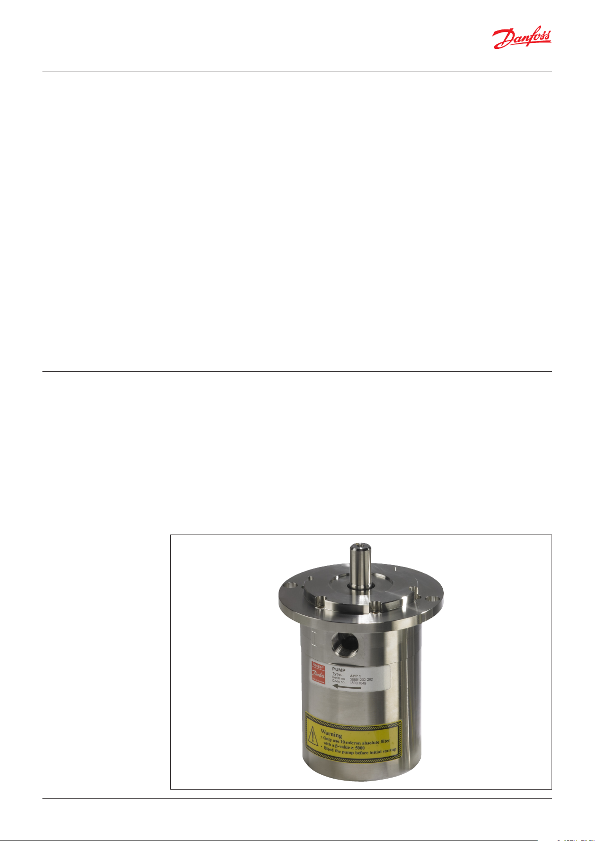
Service guide
APP pumps
APP 0.6 - 1.0
Disassembling and assembling
hpp.danfoss.com
Service guide | Disassembling and Assembling, APP 0.6-1.0
Table of Contents
Contents
Introduction ................................................................................................................................................................................2
1. Disassembling and assembling the pump .............................................................................................................3
2. Removal of flushing valve.............................................................................................................................................6
3. Change of shaft seal .......................................................................................................................................................7
4. Exploded view APP 0.6-1.0 ........................................................................................................................................ 10
Introduction
NOTE: If the pump is disassembled within the warranty period, the pump is no longer covered
by the warranty.
This document covers the instructions for
disassembling and assembling the axial piston
pump APP 0.6-1.0
Important: It is essential that the pump is
serviced in conditions of absolute cleanliness.
To understand the pump design better, please
see exploded view on last page.
Tools needed:
• Shaft seal tool (code no. 180B4142)
• Seal set (code no. 180B4141)
• 2 Screwdrivers
WARNING: Do not reuse disassembled O-ring
or shaft seal as they might be damaged.
© Danfoss | DCS (im) | 2017.082 | 180R9092 | DKCFN.PI.013.EC5.02 | 521B0739
Service guide | Disassembling and Assembling, APP 0.6-1.0
1. Disassembling and
assembling the pump
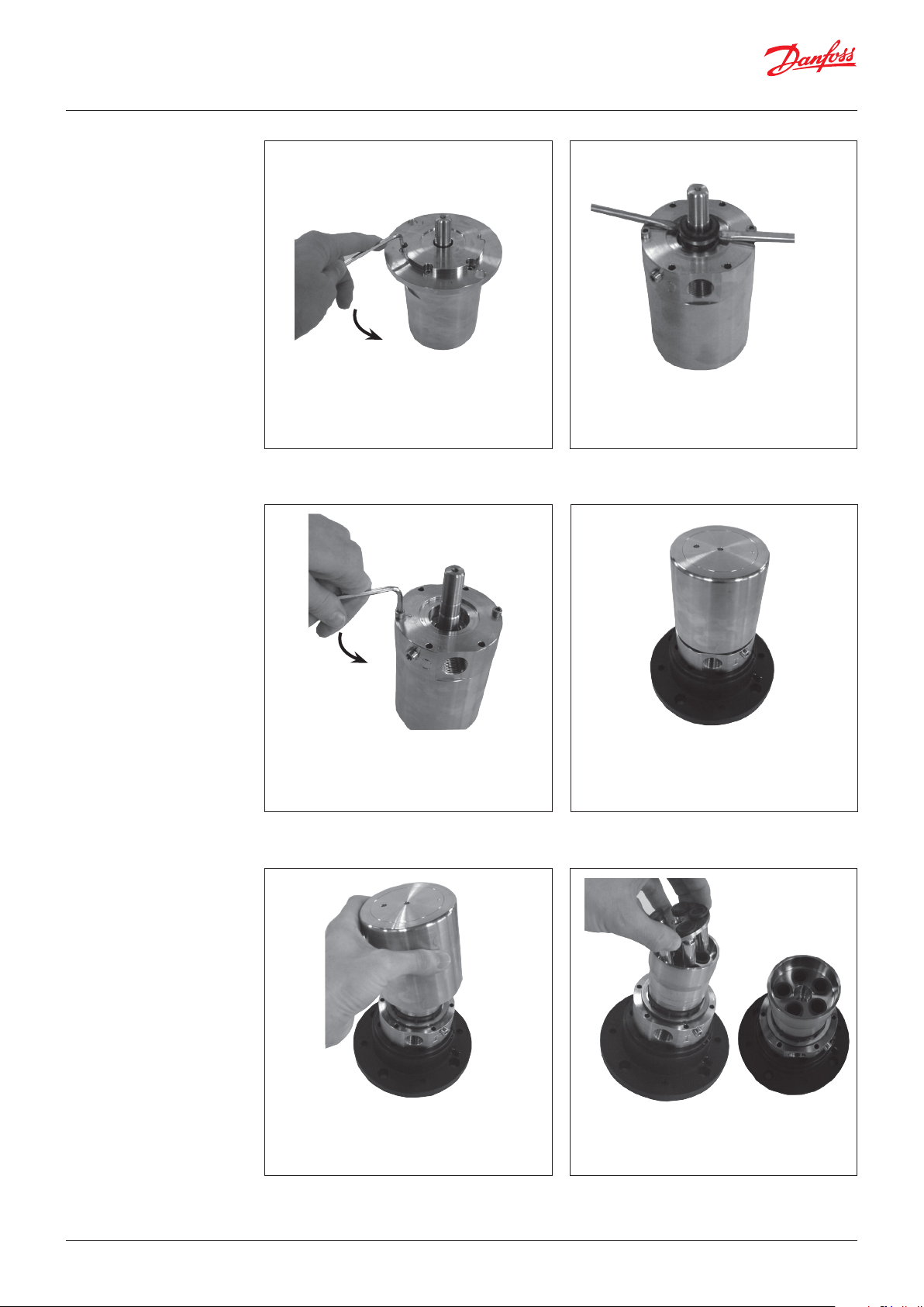
1. Unscrew the 4 mounting screws and
remove seal SAE flange.
Do not yet unscrew the 2 lower screws.
3. Unscrew the 2 lower screws.
2. Wet the shaft and shaft seal with clean
(filtered) soap water. Gently lever the shaft
seal assembly free using 2 screwdrivers.
4. Carefully turn the whole pump over so
that the shaft is facing down. Support the
pump in a suitable hollow base so that the
pump is not supported by the shaft.
5. Remove the housing.
© Danfoss | DCS (im) | 2017.08 180R9092| DKCFN.PI.013.EC5.02 | 521B0739| 3
6. Remove the pistons, retaining plate,
retaining ball, spring guide, and spring
from the cylinder barrel.
Service guide | Disassembling and Assembling, APP 0.6-1.0
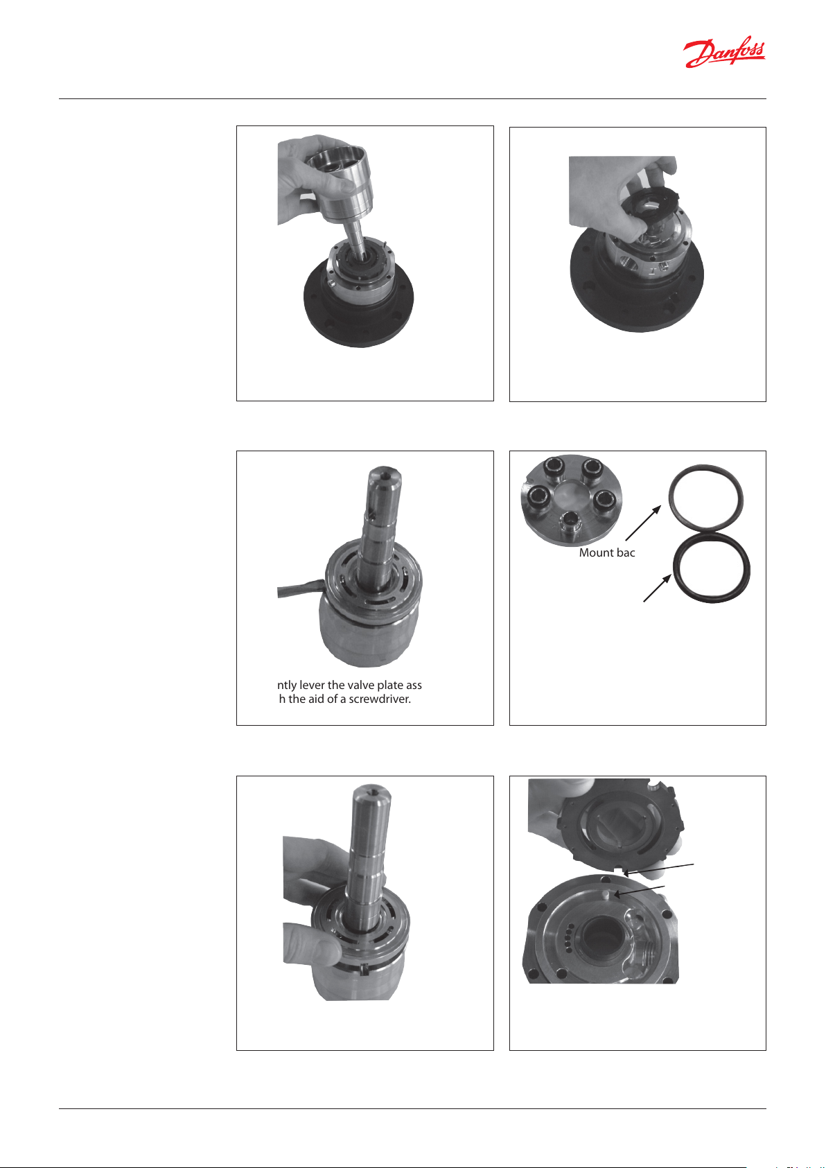
7. Remove the cylinder barrel.
9. Gently lever the valve plate assembly free
with the aid of a screwdriver.
8. Remove the port plate and guide pin.
Mount backup
ring first
Then mount
O-ring
10. Replace the O-rings and the back-up rings
on the valve plate. Mount the new back up rings on the new valve plate first and
then mount the new O-rings.
Wet the O-rings and back-up rings with
clean (filtered) soap water.
11. Gently press, by hand, the valve onto the
cylinder barrel.
Locating hole
Guide pin
12. Position the port plate over the guide pin.
IMPORTANT: Make sure that the guide
pin is located in the locating hole in the
port plate
© Danfoss | DCS (im) | 2017.084 | 180R9092 | DKCFN.PI.013.EC5.02 | 521B0739

Service guide | Disassembling and Assembling, APP 0.6-1.0
O-ring
13. Replace O-ring on the port flange and
position the new cylinder barrel on the
port plate.
15. Position the housing on the port flange
and over the guide pin.
14. Position the new spring, new spring
guide, new retaining ball, new retainer
and new pistons.
16. Hold the pump topgether and carefully
turn it over to rest on the housing. To
prevent seizing-up, lubricate the threads
on the 2 screws and screw them into the
port flange and the housing. Use Molykote
D paste from Dow Corning or Klüber UH1
84-201 from Klüber lubrication. Tighten
the 2 flange screws accordiing to exploded
view.
18. Replace the O-ring on the SAE flange.17.Mount the new shaft seal following the
instructions on page
© Danfoss | DCS (im) | 2017.08 180R9092| DKCFN.PI.013.EC5.02 | 521B0739| 5

Service guide | Disassembling and Assembling, APP 0.6-1.0
19. Lubricate the threads on the 4 screws with
grease and screw them into the pump and
tighten by hand. Use Molykote D paste
from DOW Corning or Klüber UH1 84-201
from Klüber lubrication.
Tighten screws according to exploded
view.
2. Removal of flushing valve
1.. Use a pointed plier to remove flushing
valve. Gently grab the pin with the plier
and pull it out.
3. To assemble the valve, press new spring
onto shoulders of poppet guide and
poppet so it is stuck on both shoulders.
Then mount the new O-ring on poppet
guide.
2. Assemble the new flushing valve, or
replace parts that are worn (shoulders)
4. Turnflushing valve upside down. If it is not
properly assembled spring will fall off.
© Danfoss | DCS (im) | 2017.086 | 180R9092 | DKCFN.PI.013.EC5.02 | 521B0739

Service guide | Disassembling and Assembling, APP 0.6-1.0
5. Mount flushing valve by pressing it into
the hole.
3. Change of shaft seal
6. It must be pressed down so it levels with
the surface of the port flange (same level).
In order to find out if the valve is
working correctly, the pump needs to
be further dismantled. To work correctly
a small flat edged wire is pushed against
the flushing valve. You should be avle to
move it a couple of mm and feel the load
of the spring pressing backwards.
Recessed
screws
Tools needed
Recessed
screws
1. Unscrew the 4 mounting screws and
remove the seal SAE flange.
Do not unscrew the 2 recessed screw at
this time.
2. Wet the shaft and shaft seal with
clean (filtered) soap-water. Gently lever
the shaft seal assembly free with the aid of
2 screwdrivers.
© Danfoss | DCS (im) | 2017.08 180R9092| DKCFN.PI.013.EC5.02 | 521B0739| 7

Service guide | Disassembling and Assembling, APP 0.6-1.0
3. Fit the hollow bush (torpedo) to the shaft.
Wet the torpedo and replacement shaft
seal with soap. Do not use silicone
grease.
5. Using the plastic tool provided, large
diameter first, press the seal home against
the shoulder, by hand.
4. Slide the shaft seal over the torpedo with
the carbon seal face pointing upwards. Be
careful not to damage the carbon seal
face on the shaft seal.
6. Remove ceramic ring from the flange.
7. Push the new ceramic ring into the flange
using the plastic tool provided. Make sure
the face with the rubber seal is positioned
against the shoulder in the flange.
Wet the parts with clean (filtered) soap water before assembly.
8. Position the O-ring on the seal SAE flange.
© Danfoss | DCS (im) | 2017.088 | 180R9092 | DKCFN.PI.013.EC5.02 | 521B0739

Service guide | Disassembling and Assembling, APP 0.6-1.0
9. To prevent cold welding, lubricate
threads on the 4 screws with grease and
screw them into the pump and tighten
by hand. Use Molykote® D paste from Dow
Corning or Klüber UH1 84-201 from Klüber
lubrication. Tighten the 4 flange screws
according to exploded view.
© Danfoss | DCS (im) | 2017.08 180R9092| DKCFN.PI.013.EC5.02 | 521B0739| 9

Service guide | Disassembling and Assembling, APP 0.6-1.0
4. Exploded view
APP 0.6-1.0
© Danfoss | DCS (im) | 2017.0810 | 180R9092 | DKCFN.PI.013.EC5.02 | 521B0739

Service guide | Disassembling and Assembling, APP 0.6-1.0
© Danfoss | DCS (im) | 2017.08 180R9092| DKCFN.PI.013.EC5.02 | 521B0739| 11

Danf
already on order pro
All trademarks in this material are property of the respec
Danfoss A/S
High Pressure Pumps
Nordborgvej 81
DK-6430 Nordborg
Denmark
oss can accept no responsibility for possible errors in catalogues, brochures and other printed material. Danfoss reserves the right to alter its products without notice. This also applies to products
vided that such alterations can be made without subsequential changes being necessary eady agreed.
© Danfoss | DCS (im) | 2017.08
tive companies. Danfoss and the Danfoss logotype are trademarks of Danfoss A/S. All rights reserved.
180R9092 | DKCFN.PI.013.EC5.02 | 521B0739| 12
 Loading...