

Page 1
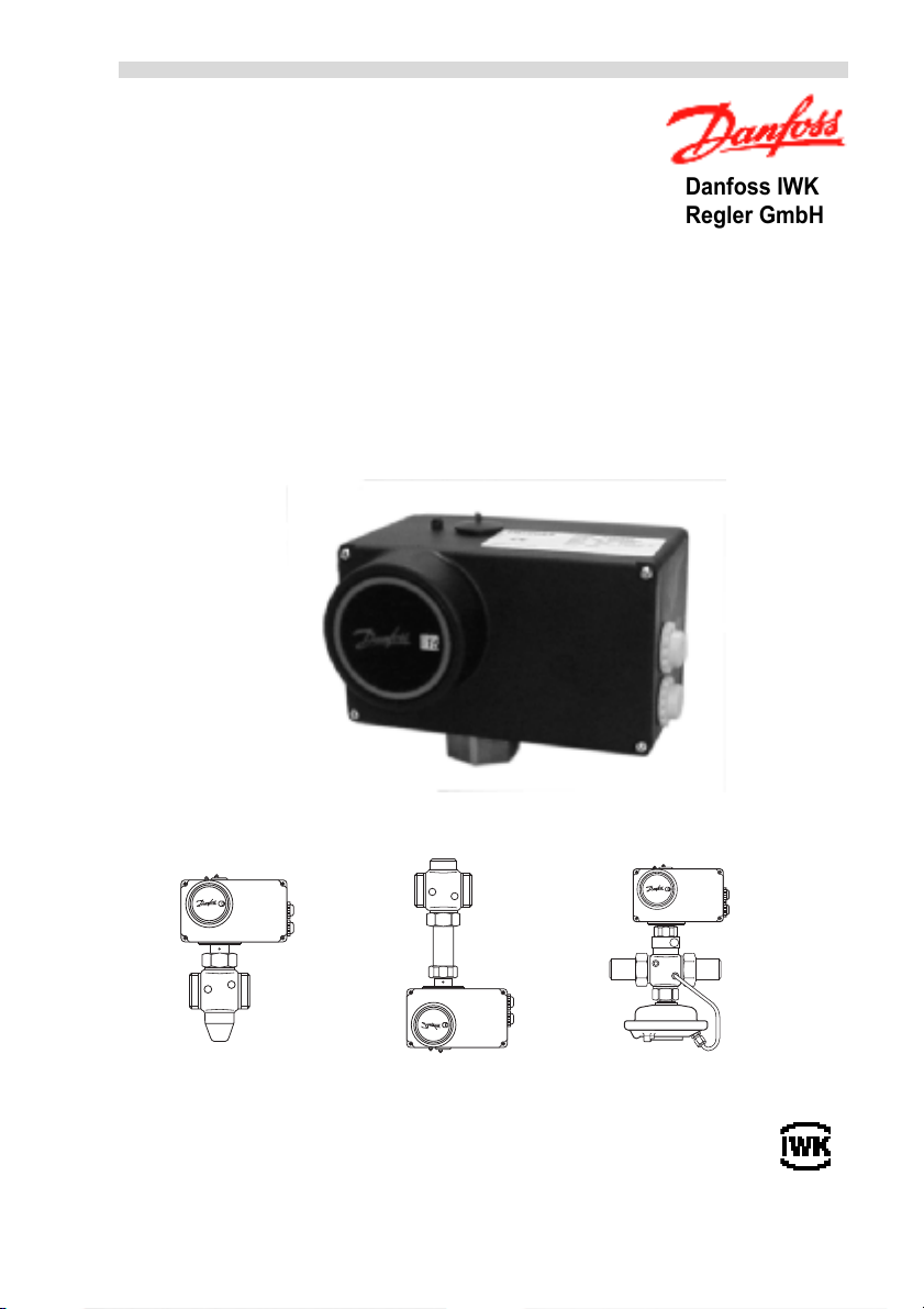
Elektrischer Stellantrieb Seite 2
Electrical Actuator Page 24
AMV213 / AME213
mit Sicherheitsfunktion
with Safety Function
AMV210 / AME210
Bedienungsanleitung / Operating Instructions
Danfoss IWK
Regler GmbH
600 000 7072
Ausgabe 2 / 6.02
VI.AB.I2.5B
AMV(E)210, 213 /
VIM2, VIU2
AMV(E)210, 213 /
VIS2
AMV(E)210, 213 /
AIQM, V63M
Page 2

Inhalt
1 Sicherheitshinweise. . . . . . . . . . . . . . . . . . . . . . . . . . . . . . . . . 3
2 Allgemeine Angaben. . . . . . . . . . . . . . . . . . . . . . . . . . . . . . . . . 3
2.1 Bestimmungsgemäße Verwendung . . . . . . . . . . . . . . . . . . . . . . 3
2.2 Transport, Lieferung, Lagerung. . . . . . . . . . . . . . . . . . . . . . . . . . 3
2.3 Gewährleistung . . . . . . . . . . . . . . . . . . . . . . . . . . . . . . . . . . . . . . 3
3 Gerätebeschreibung . . . . . . . . . . . . . . . . . . . . . . . . . . . . . . . . . 4
3.1 Aufbau. . . . . . . . . . . . . . . . . . . . . . . . . . . . . . . . . . . . . . . . . . . . . 4
3.2 Beschreibung . . . . . . . . . . . . . . . . . . . . . . . . . . . . . . . . . . . . . . . 4
3.3 Technische Daten . . . . . . . . . . . . . . . . . . . . . . . . . . . . . . . . . . . . 5
3.4 Abmessungen . . . . . . . . . . . . . . . . . . . . . . . . . . . . . . . . . . . . . . . 6
4 Ventiltypen für AMV(E)210, 213 . . . . . . . . . . . . . . . . . . . . . . . . 6
5 Montage . . . . . . . . . . . . . . . . . . . . . . . . . . . . . . . . . . . . . . . . . . . 7
5.1 Zulässige Einbaulagen . . . . . . . . . . . . . . . . . . . . . . . . . . . . . . . . 7
5.2 Montage des Stellantriebs auf das Ventil . . . . . . . . . . . . . . . . . . 8
5.3 Elektrischer Anschluss . . . . . . . . . . . . . . . . . . . . . . . . . . . . . . . . 9
5.4 Anschlusspläne. . . . . . . . . . . . . . . . . . . . . . . . . . . . . . . . . . . . . 10
6 Mechanische Hubeinstellung. . . . . . . . . . . . . . . . . . . . . . . . . 12
6.1 Ventiltypen VIG2, VIS2, VIU2, AIQM . . . . . . . . . . . . . . . . . . . . 12
6.2 Ventil V63M. . . . . . . . . . . . . . . . . . . . . . . . . . . . . . . . . . . . . . . . 14
6.3 Einstellkennlinien V63M . . . . . . . . . . . . . . . . . . . . . . . . . . . . . . 15
7 Einstellungen AME210, AME213 . . . . . . . . . . . . . . . . . . . . . . 16
7.1 Übersicht Einstellung DIP-Schalter. . . . . . . . . . . . . . . . . . . . . . 16
7.2 Einstellung Eingangsignal. . . . . . . . . . . . . . . . . . . . . . . . . . . . . 17
7.3 Einstellung Ausgangssignal . . . . . . . . . . . . . . . . . . . . . . . . . . . 17
7.4 Zuordnung der Wirkrichtung zum Ein-, Ausgangssignal. . . . . . 18
7.5 Einstellung der Endlagen . . . . . . . . . . . . . . . . . . . . . . . . . . . . . 19
8 Handverstellung . . . . . . . . . . . . . . . . . . . . . . . . . . . . . . . . . . . 20
8.1 Stellantrieb AMV210, AME210 . . . . . . . . . . . . . . . . . . . . . . . . . 20
8.2 Stellantrieb AMV213, AME213 . . . . . . . . . . . . . . . . . . . . . . . . . 20
8.3 Stellantrieb AME210, AME213 . . . . . . . . . . . . . . . . . . . . . . . . . 21
9 Störungshinweise . . . . . . . . . . . . . . . . . . . . . . . . . . . . . . . . . . 22
9.1 Störung, Ursache, Maßnahme . . . . . . . . . . . . . . . . . . . . . . . . . 22
9.2 Störungsanzeige Stellantriebe AME210, 213 . . . . . . . . . . . . . . 23
9.3 Kundendienst . . . . . . . . . . . . . . . . . . . . . . . . . . . . . . . . . . . . . . 23
2
Page 3

Sicherheitshinweise
1 Sicherheitshinweise
Achtung!
Um Verletzungen an Personen
und Schäden am Stellantrieb zu
vermeiden, diese Anleitung unbedingt beachten.
Montage, Inbetriebnahme und
Wartungsarbeiten dürfen nur von
sachkundigen und autorisierten
Personen durchgeführt werden.
Die Vorgaben des Anlagenherstellers und Anlagenbetreibers sind zu
beachten.
2 Allgemeine Angaben
2.1 Bestimmungsgemäße
Verwendung
Der elektrische Stellantrieb ist einsetzbar für Danfoss-Durchgangsventile in den Nennweiten
DN 15 – 50 und für die Nenndrücke PN 16/25.
Die technischen Daten auf den Typenschildern und die im
Abschnitt 3.3 angegebenen Daten
sind für den Einsatz maßgebend.
2.2 Transport, Lieferung,
Lagerung
Zulässige Umgebungsbedingungen bei Lagerung und
Transport
Umgebungstemperatur:
-10 °C bis +70 °C
Geräte sind zu schützen vor:
l Nässe
l Feuchtigkeit
l Verschmutzung
l Stößen
Prüfung der Lieferung
Die Sendung ist sofort nach Erhalt
auf Vollständigkeit zu überprüfen.
Die Daten des Geräts sind mit den
Angaben auf dem Lieferschein
und der Bestellunterlagen zu vergleichen.
2.3 Gewährleistung
Ein Gewährleistungsanspruch
setzt eine fachgerechte Montage
und Inbetriebnahme nach der für
das Gerät gültigen Montage-, Inbetriebnahme und Wartungsvorschrift voraus.
3
Page 4

Gerätebeschreibung
3 Gerätebeschreibung
3.1 Aufbau
Hubbegrenzungsschraube
Hubanzeige
Schubstange
3.2 Beschreibung
Die Antriebseinheit besteht aus
einem Stirnradgetriebe mit einem
Synchronmotor. Die Umformung
der Drehbewegung in eine axiale
Bewegung der Schubstange
erfolgt über ein Zahnradsegment.
In den Endlagen erfolgt die
Abschaltung des Stellantriebs
beim Erreichen einer definierten
Stellkraft.
Der Maximalhub des elektrischen
Stellantriebs wird entsprechend
dem Ventilhub mittels der Hubbegrenzungsschraube eingestellt.
Stellungsregler
(ISR-Ausführung)
Bei dieser Ausführung wird das
von einer elektrischen Regeleinrichtung kommende Stellsignal
(0(4)−20 mA / 0(2)−10 V) mit dem
Mechanische
Handverstellung
AMV(E)210
Stellhubsignal eines Potentiometers verglichen. Aus der Differenz dieser Signale wird ein
Dreipunkt-Schritt-Signal zur Ansteuerung des Synchronmotors
abgeleitet.
Mechanische Handverstellung
Die Verstellung des Hubes kann
bei den Typen AMV(E)210 aussen
mittels Drehknopf erfolgen. Bei
den Typen AMV(E)213 nach
Abschrauben des Gehäusedeckels mittels eines Innensechskantschlüssels.
Endschalter
(Zusatzausrüstung)
Die zwei potentialfreien Endschalter schalten automatisch in den
Endlagen. Eine Einstellung ist
nicht erforderlich.
4
Page 5
Gerätebeschreibung
3.3 Technische Daten
AMV210 AMV213 AME210 AME213
Sicherheitsfunktion
2)
Hub mm 15
Stellzeit s/mm 12
Stellkraft N 300
Spannungsversorgung V 230 V
Leistungsaufnahme VA 8
Eingangssignal Dreipunkt-Schritt-
Ausgangsignal – 0(2)–10 V
Verhalten bei Ausfall
der Netzversorgung
Schutzart nach
EN 60529
Schutzklasse DIN VDE 0106 II
Umgebungstempera-
°C -10 bis +50
tur im Betrieb
-ja-ja
+10 % -15 %, 50/
60 Hz
24 V +10 % -15 %,
50/60 Hz
0(4)–20 mA
Signal
0(2)–10 V
230 V, 50/60 Hz
1) 2) 1) 2)
IP 54 bei Einbaulage senkrecht nach oben ste-
hend, andere Einbaulagen IP 52
Umgebungstempera-
° C -10 bis +70
tur bei Lagerung,
Transport
Endlagenabschaltung drehmomentabhängige Abschaltung
Zusatzausrüstung (nicht nachrüstbar)
Endschalter (2 Stück)
(nur Ausführung AMV210, 213)
1)
Schubstange verharrt in letzter Position
2)
Schubstange fährt aus
potentialfrei, Wechsler, max. 250 V AC oder DC,
2 A ohmsche Belastung, 1 A induktive Belastung
5
Page 6
Ventiltypen für AMV(E)210, 213
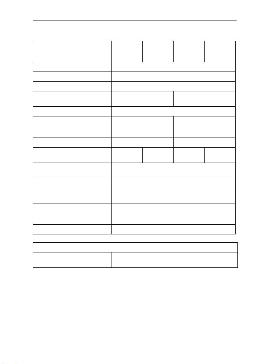
3.4 Abmessungen
90
SW 36
M34x1,5
152
117
118
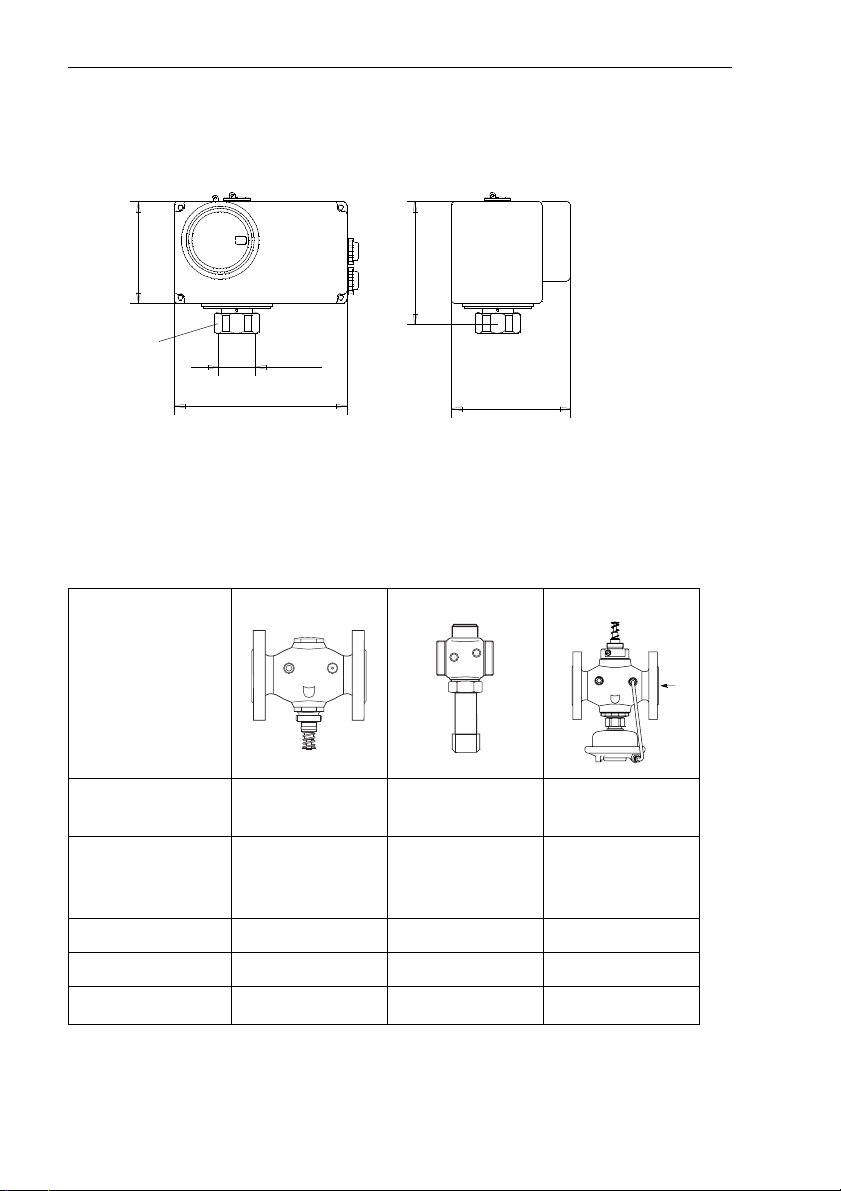
4 Ventiltypen für AMV(E)210, 213
Der elektrische Stellantrieb AMV(E)210, 213 kann auf folgende Ventile montiert werden:
Ventiltyp VIM2, VIU2 VIS2 AIQM
V63M
Beschreibung Motordurch-
gangsventil
Motordurch-
gangsventil für
Dampf
Volumen-
stromregler mit
Motorventil
DN 15 - 50 15 - 25 15 - 50
Medium Heisswasser Dampf Heisswasser
t
max. Medium
° C 150 200 150
Den Stellventilen ist eine separate Montageanleitung beigefügt.
6
Page 7
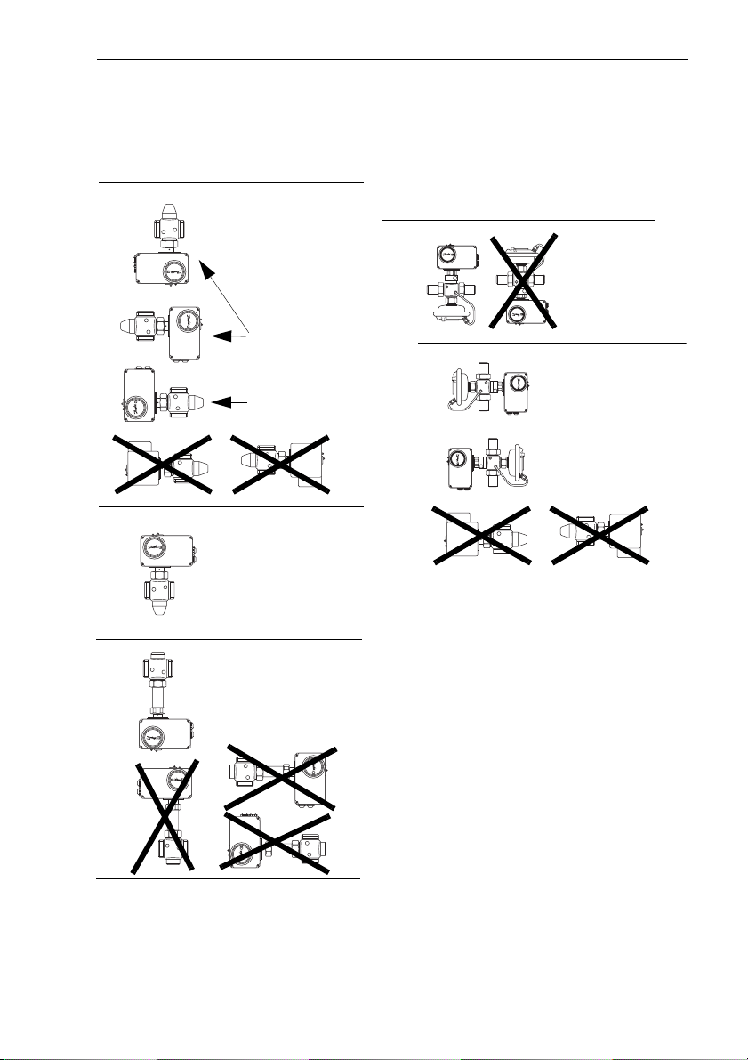
5 Montage
5.1 Zulässige Einbaulagen
VIM2
Schutzart
Stellantrieb IP 52
vorzugsweise
Montage
AIQM
Schutzart
Stellantrieb
IP 54
mögliche
Einbaulage
VIM2
Schutzart
Stellantrieb IP 54
VIS2
max. 200 °C
Schutzart
Stellantrieb IP 52
AIQM
Schutzart
Stellantrieb
IP 52
7
Page 8
Montage
5.2 Montage des Stellantriebs
auf das Ventil
Vor der Montage beachten:
Gefahr durch Stromschlag!
Bei unsachgemäßer Handhabung besteht Lebens- oder Verletzungsgefahr. Stellantrieb
kann beschädigt werden.
Bei elektrisch angeschlossenem
Stellantrieb vor der Montage
Spannungsversorgung abschalten.
1. Stellantrieb auf das Ventil auf-
setzen.
2. Überwurfmutter
ben und
SW 36 anziehen,
Anzugsmoment 35 Nm.
mit Gabelschlüssel
1 aufschrau-
3. Kreuzschlitzschrauben (4x)
lösen und Deckel abnehmen.
Unbedingt Montagehilfe (Stift
mit gelbem Kopf) entfernen!
Wird der Stift nicht entfernt, dann
ist der Stellantrieb blockiert.
Stift
1
4. Elektrischen Anschluss durchführen (siehe nächsten
Abschnitt).
8
Page 9
5.3 Elektrischer Anschluss
Gefahr durch Stromschlag!
Bei unsachgemäßer Handhabung besteht Lebens- oder Verletzungsgefahr.
Vor dem Anschluss der Leitungen
unbedingt Spannungsversorgung
abschalten.
Durchführung des elektrischen
Anschlusses nur durch Elektrofachkraft.
Montage
2
1
3
1. Deckel
Abschnitt 5.2, Punkt 3
2. Die Netzversorgungsspannung überprüfen.
Sie muss mit der Angabe auf
dem Typenschild
Anschlussplan
men.
3. Kabelverschraubung
männisch durchstoßen um
Schutzart zu gewährleisten.
4. Leitungen durchführen und
entsprechend dem Anschluss-
plan (siehe nächste Seite)
den Klemmen
1 demontieren siehe
und auf dem
2 übereinstim-
3 fach-
4 anschließen.
an
4
5
5. Bei Anschluss von STB, STW,
SDB an den Klemmen 3 und 4
das Kabel
6. Deckel
dem die Hubeinstellung
(Abschnitt 6) und die Einstellungen für AME210, 213
(Abschnitt 7) abgeschlossen
sind.
5 entfernen.
1 erst montieren nach-
9
Page 10
Montage
5.4 Anschlusspläne
Der Anschlussplan im Deckel ist maßgebend.
Anschlussplan AMV210
10
Anschlussplan AMV213
Anschlussplan Endschalter
(Zusatzausrüstung
für AMV2..)
Page 11
Montage
AME 213
Anschlussplan AME210
Anschlussplan AME213
Eingang
Regler
Eingang
Regler
Ausgangssignal, proportional
Stellhub
Ausgangssignal, proportional
Stellhub
11
Page 12
Mechanische Hubeinstellung
6 Mechanische Hubein-
stellung
Der Hub des elektrischen Stellantriebs (Maximalhub 15 mm) muss
nach der Montage dem Ventilhub
angepasst werden.
Dadurch wird ein „Leerhub“ des
Stellantriebs und eine eventuell
auftretende instabile Regelung
verhindert.
Gefahr durch Stromschlag!
Bei unsachgemäßer Handhabung besteht Lebens- oder Verletzungsgefahr. Stellantrieb
kann beschädigt werden.
Vor der Hubeinstellung unbedingt Spannungsversorgung
abschalten.
durch:
AMV213, AME213
Das Ventil schließt (VIU2 öffnet) automatisch bei abgeschalteter Spannungsversorgung, weiter mit 3.
AMV210, AME210
l Kreuzschlitzschrauben (4x)
lösen und Deckel abnehmen
l Mit Innensechskantschlüssel
SW 4 Welle
Kraft drehen bis Widerstand
spürbar ist
1 mit geringer
6.1 Ventiltypen VIG2, VIS2,
VIU2, AIQM
1. Sicherstellen, dass die Span-
nungsversorgung abgeschaltet ist.
2. Ventil schließen (VIU2 öffnen)
VIG2, VIS2,
AIQM
12
VIU2
1
➻➻➻➻ das Ventil ist geschlossen
(VIU2 geöffnet)
Page 13
Mechanische Hubeinstellung
3. Hubanzeige auf 0 justieren
justieren
4. Abdeckschraube
1 heraus-
schrauben
1
5. Hubbegrenzungsschraube
bis zum Anschlag nach rechts
eindrehen
2
➻➻➻➻ Hub des Stellantriebs ist auf
0 mm eingestellt
2
T1 Ventilhübe VIM2, AIQM, VIS2, VIU2
Nennweite
VIM2
AIQM
VIS2 Ventilhub mm 5
VIU2 Ventilhub mm 5
DN 15 20 25 32 40 50
Ventilhub mm 8 10 15
Umdrehungen
Hubbegrenzungsschraube
Umdrehungen
Hubbegrenzungsschraube
Umdrehungen
Hubbegrenzungsschraube
6,5 8 12
4
größer 5
13
Page 14
Mechanische Hubeinstellung
6. Aus der Tabelle T1 die
„Anzahl der Umdrehungen
Hubbegrenzungsschraube“
ablesen.
7. Hubbegrenzungsschraube um
diese Anzahl Umdrehungen
nach links herausdrehen
➻➻➻➻ Hubeinstellung ist abge-
schlossen
8. Deckel und Abdeckschraube
montieren
6.2 Ventil AIQM5
Vorgehensweise ist zunächst
identisch wie bei den Ventilen
VIG2, siehe Abschnitt 6.1.
Unter Punkt 7 müssen die Anzahl
der erforderlichen Umdrehungen
der Hubbegrenzungsschraube
aus den Einstellkennlinien (siehe
Abschnitt 6.3) abgelesen werden.
Beispiel:
Ventil DN 15, kvs=1,6 m³/h
Der Volumenstrom soll auf
0,2 m³/h begrenzt werden.
Vorgehensweise:
1. Diagramm auswählen
2. Für den Volumenstrom von
0,2 m³/h die Anzahl Umdrehungen Hubbegrenzungsschraube ablesen:
3,5 Umdrehungen
3. Hubbegrenzungsschraube um
diese Anzahl Umdrehungen
herausdrehen (Linksdrehung)
14
Page 15

6.3 Einstellkennlinien AIQM5
Mechanische Hubeinstellung
DN 15 Kvs 1,6 m³/h
0,7
0,6
0,5
0,4
0,3
Beispiel
0,2
Volumenstrom (m³/h)
0,1
0
12 34 5 67
Umdrehungen
Hubbegrenzungsschraube
DN 15 Kvs 4 m³/h
2,5
2
1, 5
1
0,5
Volumenstrom (m³/h)
0
1234567
Umdrehungen
Hubbegrenzungsschraube
DN32 Kvs 12,5 m³/h
10
9
8
7
6
5
4
3
2
Volumenstrom (m³/h)
1
0
123456789101112
Umdrehungen
Hubbegrenzungsschraube
DN 15 Kvs 2,5 m³/h
1, 4
1, 2
1
0,8
0,6
0,4
Volumenstrom (m³/h)
0,2
0
1234567
Umdrehungen
Hubbegrenzungsschraube
DN 20 Kvs 6,3 m³/h / DN 25 Kvs 8 m³/h
5
Max. Volumenstrom DN 25
4,5
4
Max. Volumenstrom DN 20
3,5
3
2,5
2
1, 5
1
Volumenstrom (m³/h)
0,5
0
123456789
Umdrehungen
Hubbegrenzungsschraube
DN 40 Kvs 16 m³/h / DN 50 Kvs 20 m³/h
16
Max. Volumenstrom DN 50
14
12
Max. Volumenstrom DN 40
10
8
6
4
Volumenstrom (m³/h)
2
0
23456789101112
Umdrehungen
Hubbegrenzungsschraube
15
Page 16

Einstellungen AME210, AME213
7 Einstellungen AME210, AME213
Vor der Inbetriebnahme müssen die Einstellungen für die Ein-, Ausgangssignale und der Abgleich für die Endlagen durchgeführt werden.
7.1 Übersicht Einstellung DIP-Schalter
ON
ON
ON
OFF
1 2 3 4 5 6 7 8
1 Ohne Funktion Ohne Funktion
2 Eingangssignal 4 - 20 mA
2 - 10 V
Eingangssignal 0 - 20 mA
0 - 10 V
3 Ausgangsignal 2 - 10 V Ausgangsignal 0 - 10 V 7.3
47.4
Inversbetrieb
5
Automatikbetrieb
6 Handbetrieb:
Schubstange ausfahren
7 neuer Abgleich der Endlage
erfolgt nicht
20 mA
10 V
0(2, 4)
0 Hub 100 %
Normalbetrieb
1)
Handbetrieb 8.3
Handbetrieb:
Schubstange einfahren
Beim Einschalten der Spannungsversorgung fährt
Schubstange aus bis Ventil
zu ist,
Endlage „Ventil zu“ wird neu
abgeglichen
8 Störungsanzeige EIN Störungsanzeige AUS 9.3
1 2 3 4 5 6 7 8
20 mA
10 V
0(2, 4)
0 Hub 100 %
siehe Abschnitt
7.2
8.3
-
1)
im Regelbetrieb unbedingt auf Automatikbetrieb stellen.
Die Stellung der Schalterstellungen 1, 6, 7, 8 haben im normalen Regelbetrieb keinen Einfluss.
16
Page 17

Einstellungen AME210, AME213
7.2 Einstellung Eingangsignal 7.3 Einstellung
Ausgangssignal
Das Ausgangsignal 0(2) - 10 V ist
proportional dem Stellhub.
S1 S2
S1
S2
ON
1 2 3 4 5 6 7 8
Eingangssignal
0(4) - 20 mA
0(2) - 10 V
Offset Eingangsignal
0 - 20 mA
0 - 10 V
S2
ON
1 2 3 4 5 6 7 8
ON
1 2 3 4 5 6 7 8
Offset Ausgangsignal
0 - 10 V
2 - 10 V
ON
1 2 3 4 5 6 7 8
4 - 20 mA
2 - 10 V
17
Page 18

Einstellungen AME210, AME213
7.4 Zuordnung der Wirkrichtung zum Ein-, Ausgangssignal
Ventile: VIM2, VIS2, AIQM
ON
S2
1 2 3 4 5 6 7 8
20 mA
10 V
Ein-,
Ausgangsignal
0(2, 4)
0 Hub 100 %
ON
S2
1 2 3 4 5 6 7 8
20 mA
10 V
Ein-,
Ausgangsignal
Normalbetrieb
Ventil: VIU2
ON
S2
1 2 3 4 5 6 7 8
0(2, 4)
0 Hub 100 %
ON
S2
1 2 3 4 5 6 7 8
18
20 mA
10 V
Ein-,
Ausgangsignal
0(2, 4)
0 Hub 100 %
Inversbetrieb
20 mA
10 V
Ein-,
Ausgangsignal
0(2, 4)
0 Hub 100 %
Page 19

Einstellungen AME210, AME213
7.5 Einstellung der Endlagen
Nach der Durchführung der Hubeinstellung (siehe Abschnitt 6)
müssen die Endlagen „Ventil AUF“
und „Ventil ZU“ noch mit den
Strom-, Spannungswerten
0(4) - 20 mA, 0(2) - 10 V abgeglichen werden.
1. Versorgungsspannung ein-
schalten
➻
➻ grüne LED 1 muss blinken
➻➻
rote LED
aus sein
2 kann blinken oder
S2
Während des Abgleichvorgangs blinkt die rote LED
sie wird am Ende ausgeschaltet.
Die Einstellungen sind abgeschlossen, der elektrische
Stellantrieb befindet sich im
Automatikbetrieb.
4. Deckel
Kreuzschlitzschrauben anziehen.
4 aufsetzen und
4
2,
3
1 2
2. Schalter
S2 einstellen:
S2
ON
Automatik-
1 2 3 4 5 6 7 8
3. Taster
3 kurz drücken
betrieb
➻➻➻➻ Der Antrieb fährt mehrmals
auf und zu, dadurch werden
die Endlagen automatisch
abgeglichen.
19
Page 20

Handverstellung
8 Handverstellung
Vor der Betätigung der mechanischen Handverstellung Spannungsversorgung unterbrechen.
8.1 Stellantrieb AMV210,
AME210
Handverstellung erfolgt durch drehen des Drehknopfes:
l Schubstange des Stellan-
triebs einfahren
l Schubstange des Stellan-
triebs ausfahren
VIM2, VIS2,
AIQM
8.2 Stellantrieb AMV213,
AME213
Die Handverstellung kann nach
demontieren des Deckels mittels
eines Innensechskantschlüssels
SW 4 erfolgen.
VIU2
20
VIM2
VIS2
AIQM
VIU2
1
Drehrichtung siehe unter 8.1.
Stellung mit Stift
1 blockieren
Page 21

Handverstellung
8.3 Stellantrieb AME210,
AME213
Bei diesen Stellantrieben kann die
Handverstellung bei demontiertem
Deckel auch elektrisch durchgeführt werden.
S2
3
l Schubstange des Stellan-
triebs einfahren
l Schubstange des Stellan-
triebs ausfahren
VIM2
VIS2
VIU2
AIQM
durch Einstellung des Schalters S2
S2
ON
Schubstan-
1 2 3 4 5 6 7 8
und drücken des Tasters
ge ausfahren
3
VIM2
VIS2
VIU2
AIQM
durch Einstellung des Schalters S2:
S2
ON
1 2 3 4 5 6 7 8
und drücken des Tasters
Schubstange einfahren
Für den Regelbetrieb unbedingt
auf Automatikbetrieb umstellen:
S2
ON
Automatik-
1 2 3 4 5 6 7 8
betrieb
3
21
Page 22

Störungshinweise
9 Störungshinweise
9.1 Störung, Ursache, Maßnahme
Störung Mögliche Ursache Maßnahme
Keine Funktion des
Stellantriebs
Wirkungsrichtung des
Stellantriebs ist umgekehrt
Netzspannung ausgeschaltet
kein Steuersignal von
der elektrischen
Regeleinrichtung
Sicherheitseinrichtung STB, STW oder
SDB hat angesprochen
Montagehilfe (Stift)
wurde nicht entfernt
Stellantrieb defekt siehe auch 9.2
Ausführung AME2...,
DIP Schalter steht auf
Handbetrieb
Ausführung AMV2 ...,
Anschluss an den
Klemmen 6 und 7 vertauscht, siehe Abschnitt 5.4
Ausführung AME2...,
DIP Schalter steht auf
„Inversbetrieb“
Netzspannung überprüfen
Regeleinrichtung
überprüfen
Anlage, Sicherheitseinrichtung überprüfen
Montagehilfe entfernen, siehe Abschnitt
5.2 Punkt 4
auf Automatik stellen,
siehe Abschnitt 7.1,
Schalter 5
Anschluss der Klemmen tauschen
auf „Normalbetrieb“
umstellen, siehe Abschnitt 7.4
22
Page 23

9.2 Störungsanzeige
Stellantriebe AME210, 213
Eine Störung kann angezeigt werden durch:
Störungshinweise
1. die Leuchtdioden
1 und 2
2. das Ausgangsignal >11V
(Klemmen 7 (+) und 5),
wenn der Schalter
de Stellung hat:
S2
ON
1 2
Störungsanzeige Störung Maßnahme
Ausgangsignal >11V
und
Leuchtdiode rot
blinkt, ca. 2,5 mal pro
Sekunde
Leuchtdiode grün
leuchtet nicht
S2
Stellantrieb defekt
oder
Ventilstange ist blockiert, d. h. Stellan-
2
trieb kann Position
nicht anfahren
Spannungsversor-
1
gung unterbrochen
1 2 3 4 5 6 7 8
Stellantrieb austauschen
Ventil überprüfen,
lässt sich die Ventilstange verschieben?
Eventuell Ventil austauschen
Spannungsversorgung und elektrischen
Anschluss prüfen
S2 folgen-
Störungsanzeige >11V
EIN
9.3 Kundendienst
Bei Fragen und Störungen können Sie unseren Kundendienst anrufen:
Tel. 0 72 44 / 7205 - 287 oder 7205 - 5 04, Fax 0 72 44 / 7205 306
Kundendienst-Hotline 01 80 / 3 21 26 86
23
Page 24

Störungshinweise
Content
1 Safety Notes . . . . . . . . . . . . . . . . . . . . . . . . . . . . . . . . . . . . . . . 3
2 General Information . . . . . . . . . . . . . . . . . . . . . . . . . . . . . . . . . 3
2.1 Definition of Application . . . . . . . . . . . . . . . . . . . . . . . . . . . . . . . 3
2.2 Transportation, Delivery, and Storage . . . . . . . . . . . . . . . . . . . . 3
2.3 Warranty . . . . . . . . . . . . . . . . . . . . . . . . . . . . . . . . . . . . . . . . . . . 3
3 Device Description . . . . . . . . . . . . . . . . . . . . . . . . . . . . . . . . . . 4
3.1 Construction . . . . . . . . . . . . . . . . . . . . . . . . . . . . . . . . . . . . . . . . 4
3.2 Description . . . . . . . . . . . . . . . . . . . . . . . . . . . . . . . . . . . . . . . . . 4
3.3 Technical Data . . . . . . . . . . . . . . . . . . . . . . . . . . . . . . . . . . . . . . 5
3.4 Dimensions. . . . . . . . . . . . . . . . . . . . . . . . . . . . . . . . . . . . . . . . . 6
4 Valve Types for AMV(E)210, 213 . . . . . . . . . . . . . . . . . . . . . . . 6
5 Mounting . . . . . . . . . . . . . . . . . . . . . . . . . . . . . . . . . . . . . . . . . . 7
5.1 Permitted Installation Positions. . . . . . . . . . . . . . . . . . . . . . . . . . 7
5.2 Mounting the Actuator on the Valve . . . . . . . . . . . . . . . . . . . . . . 8
5.3 Electrical Connection . . . . . . . . . . . . . . . . . . . . . . . . . . . . . . . . . 9
5.4 Connection Diagram. . . . . . . . . . . . . . . . . . . . . . . . . . . . . . . . . 10
6 Mechanical Stroke Setting . . . . . . . . . . . . . . . . . . . . . . . . . . . 12
6.1 Valve Types VIG2, VIS2, VIU2, AIQM . . . . . . . . . . . . . . . . . . . 12
6.2 Valve V63M . . . . . . . . . . . . . . . . . . . . . . . . . . . . . . . . . . . . . . . 14
6.3 Flow Adjusting Curves V63M . . . . . . . . . . . . . . . . . . . . . . . . . . 15
7 Adjustments AME210, AME213 . . . . . . . . . . . . . . . . . . . . . . 16
7.1 Overview DIP switch settings . . . . . . . . . . . . . . . . . . . . . . . . . 16
7.2 Input Signal Settings. . . . . . . . . . . . . . . . . . . . . . . . . . . . . . . . . 17
7.3 Output Signal Settings . . . . . . . . . . . . . . . . . . . . . . . . . . . . . . . 17
7.4 Assignment of the effective direction to the input/output signal 18
7.5 Setting the End Positions . . . . . . . . . . . . . . . . . . . . . . . . . . . . . 19
8 Manual Adjustment. . . . . . . . . . . . . . . . . . . . . . . . . . . . . . . . . 20
8.1 Actuator AMV210, AME210 . . . . . . . . . . . . . . . . . . . . . . . . . . . 20
8.2 Actuator AMV213, AME213 . . . . . . . . . . . . . . . . . . . . . . . . . . . 20
8.3 Actuator AME210, AME213 . . . . . . . . . . . . . . . . . . . . . . . . . . . 21
9 Troubleshooting . . . . . . . . . . . . . . . . . . . . . . . . . . . . . . . . . . . 22
9.1 Fault, cause, remedy . . . . . . . . . . . . . . . . . . . . . . . . . . . . . . . . 22
9.2 Fault Indicator Actuators AME210, 213 . . . . . . . . . . . . . . . . . . 23
24
Page 25

Safety Notes
1 Safety Notes
Achtung!
To avoid injury of persons and
damages to the device, it is absolutely necessary to carefully
read and observe these Instructions.
Necessary assembly, start-up, and
maintenance work may be
performed only by qualified and
authorized personnel.
Please comply with the instructions
of the system manufacturer or
system operator.
2 General Information
2.1 Definition of Application
The electrical actuator is used for
Danfoss valves with nominal
values DN 15 – 50 and for nominal
pressures PN 16/25.
The technical data on the rating
plates and the data given in
section 3.3 determine the use.
2.2 Transportation, Delivery,
and Storage
Permissible ambient conditions
for storage and transportation:
Ambient temperature:
-10 °C to +70 °C
The devices must be protected
against:
l Humidity
l Dampness
l Dirt
l Shocks
Verification of Delivery:
Immendiately upon receipt, the
shipment must be checked for
completeness. The data of the
device must be compared with the
information on the delivery note
and in the order documents.
2.3 Warranty
Any warranty claim requires
proper assembly and commissioning in accordance with the
applicable Assembly, Start-up,
and Maintenance Instructions for
the device.
25
Page 26
Device Description
3 Device Description
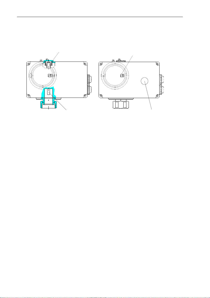
3.1 Construction
Stroke limiting
screw
Stroke indicator
Stem
3.2 Description
The actuator unit consists of a
spur gear with a synchronous
motor. The transformation of the
rotation movement into an axial
movement of the stem is realized
by means of a gear wheel segment.
When reaching a defined positioning force, the actuator is
switched off at its end positions.
The maximum stroke of the
electrical actuator is set in accordance with the valve stroke by
means of the stroke limiting screw.
Positioner
(ISR design)
With this design, the positioning
signal (0(4)−20 mA / 0(2)−10 V)
transmitted by an electrical control
unit is compared with the posi-
Mechanical
manual adjustment
AMV(E)210
tioning stroke signal of a potentiometer. A three-position step signal
is then derived from the difference
between these signals and used
to trigger the synchronous motor.
Mechanical Manual Adjustment
For the type AMV(E)210, the
stroke can be adjusted by means
of an external rotary knob. With
the type AMV(E)213, this can be
done after having removed the
housing cover by means of a
hexagon socket screw key.
End switches
(Additional equipment)
The two voltage-free end switches
automatically switch in the end
positions. There is no adjustment
required.
26
Page 27

Device Description
3.3 Technical Data
AMV210 AMV213 AME210 AME213
Safety function
2)
Stroke mm 15
Positioning time s/mm 12
Positioning force N 300
Voltage supply V 230 V
Power consumption VA 8
Input signal Three-position
Output signal – 0(2)–10 V
Behavior in case of a
drop-out
Type of protection
acc. to EN 60529
Safety class DIN VDE 0106 II
Ambient operation
°C -10 to +50
temperature
-yes-yes
+10 % -15 %, 50/
60 Hz
24 V +10 % -15 %,
50/60 Hz
0(4)–20 mA
step signal
0(2)–10 V
230 V, 50/60 Hz
1) 2) 1) 2)
IP 54 if installed in a vertical upright position,
other installation positions: IP 52
Ambient storage and
° C -10 to +70
transportation
temperature
End position switch-off Switch-off dependent on torque
Additional Equipment (cannot be added later)
End switches (2 pieces)
(only design AMV210, 213)
1)
Stem remains in last position
2)
Stem extends
voltage-free, two-way switch, max. 250 V AC or
DC, 2 A resistive load, 1 A inductive load
27
Page 28

Valve Types for AMV(E)210, 213
3.4 Dimensions
90
SW 36
M34x1,5
152
117
118
4 Valve Types for AMV(E)210, 213
The electrical actuator AMV(E)210, 213 can be mounted on the following
valves:
Valve type VIM2, VIU2 VIS2 AIQM
V63M
Description Motorized
two-way valve
Motorized
two-way valve
for steam
Flow rate
controller with
motorized
valve
DN 15 - 50 15 - 25 15 - 50
Medium Hot water Steam Hot water
t
max. medium
° C 150 200 150
Separate mounting instructions are attached to the valves.
28
Page 29
5 Mounting
4
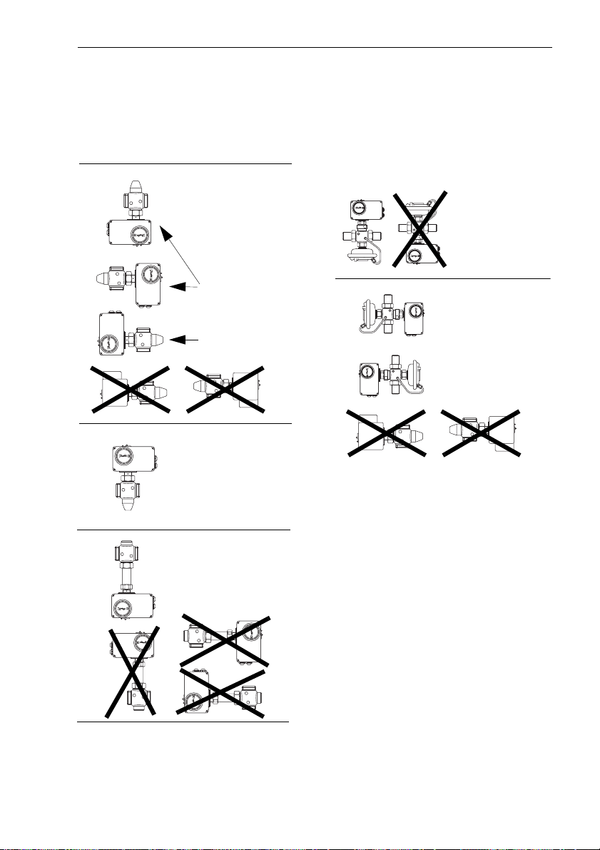
5.1 Permitted Installation
Positions
VIM2
Type of protection
actuator IP 52
preferably
Mounting
AIQM
Type of
protection
actuator IP 5
possible
installation
positon
VIM2
Type of protection
actuator IP 54
VIS2
max. 200 °C
Type of protection
actuator IP 52
AIQM
Type of
protection
actuator IP 52
29
Page 30

Mounting
5.2 Mounting the Actuator on
the Valve
Prior to mounting, please observe:
DANGER: High voltage !
Danger to life or injury in case of
unqualified handling. Actuator
can be damaged.
Prior to mounting, switch off
voltage supply when connecting
an electrical actuator.
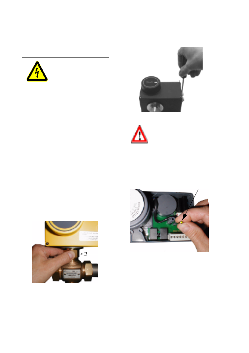
1. Put actuator on the valve.
2. Unscrew union nut
fasten with wrench SW 36,
torque 35 Nm.
1 and
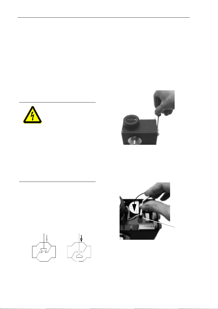
3. Loosen Philips screws (4x)
and remove cover.
It is absolutely necessary to remove the mounting aid (pin with
yellow head) !
If the pin is not removed, the
actuator is blocked.
Pin
30
1
4. Connect electrical lines
(see next section).
Page 31

5.3 Electrical Connection
DANGER: High Voltage !
Danger to life or injury in case of
unqualified handling.
It is absolutely necessary to disconnect power supply prior to connecting lines.
Electrical connection must only be
performed by qualified personnel.
Mounting
2
1
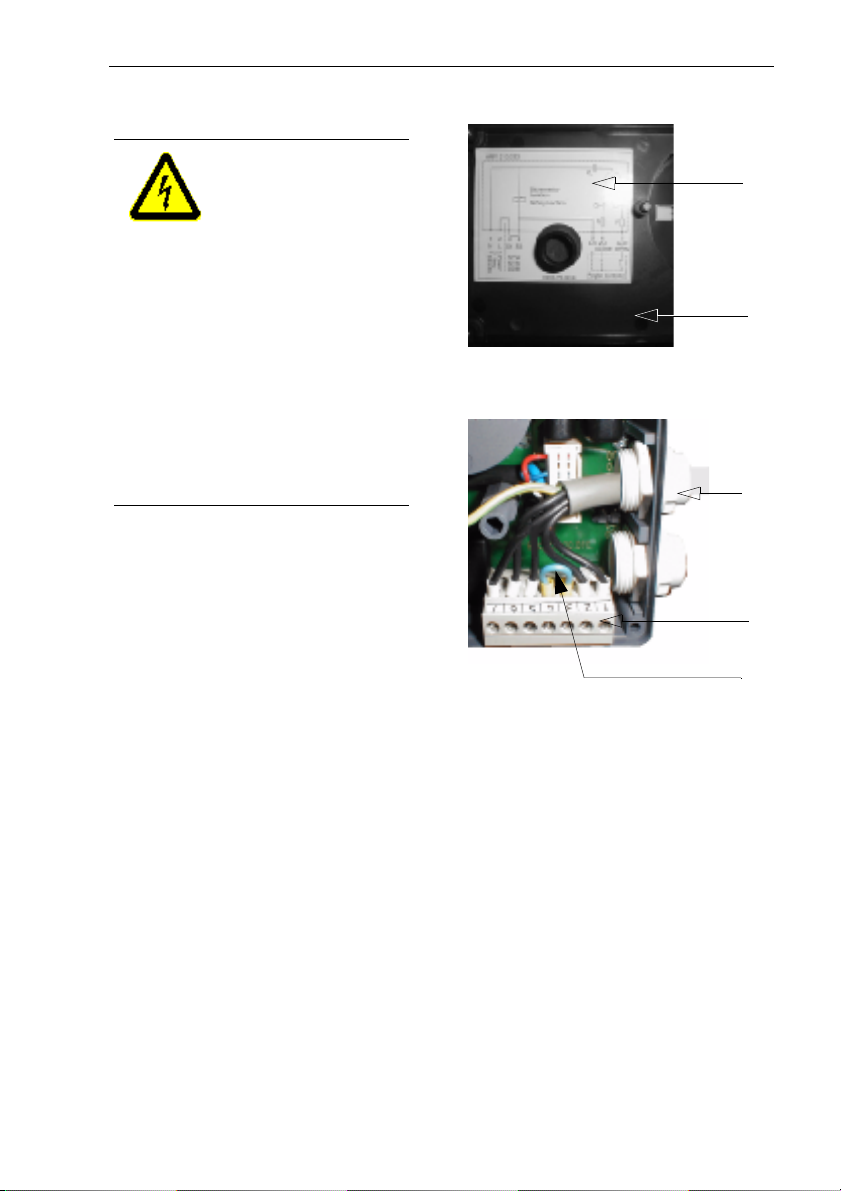
1. Dismount cover
see section 5.2, item 3,
2. Check power supply.
It must comply with the data
given on the rating plate and
on the connection diagram
3. Pierce cable gland
in order to comply with the
protection class.
4. Guide line through and connect in accordance with the
connection diagram (see next
page)
to terminals 4.
1,
3 correctly
2.
5. When connecting STB, STW,
SDB to the terminals 3 and 4,
remove cable
6. Only mount cover
having completed the stroke
settings (section 6) and the
adjustments necessary for
AME210, 213 (section 7).
5.
1 after
3
4
5
31
Page 32

Mounting
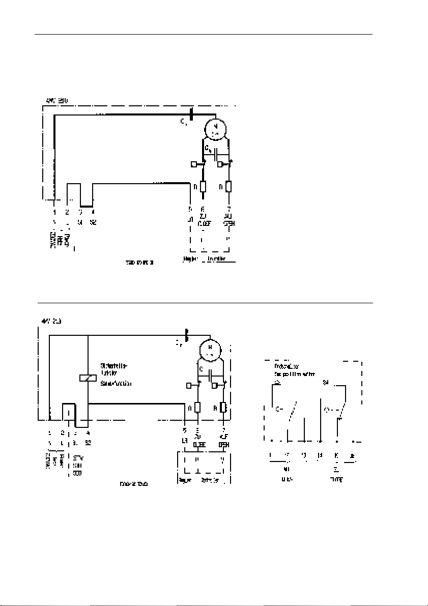
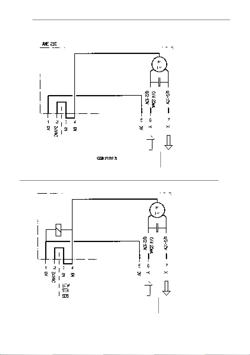
5.4 Connection Diagram
See latest connection diagram inside the cover
Connection diagram AMV210
32
Connection diagram AMV213
Connection diagram
end switches
(additional equipment
for AMV2..)
Page 33

6 Mechanical Stroke
Setting
The stroke of the electrical
actuator (maximum stroke 15 mm)
must be adjusted after having
mounted the valve stroke.
This avoids an „empty“ stroke of
the actuator and a possibly unstable control.
Prior to mounting, please observe:
DANGER: High voltage !
Danger to life or injury in case of
unqualified handling. Actuator
can be damaged.
It is absolutely necessary to
disconnect power supply prior
to setting the stroke.
Mechanical Stroke Setting
AMV213, AME213
The valve automatically closes
(VIU2 opens) when the power
is disconnected, proceed with
item 3.
AMV210, AME210
l Loosen Philips screws (4x)
an remove cover.
l Turn stem 1 with low force
with an hexagon socket screw
key until you feel resistance.
6.1 Valve Types VIG2, VIS2,
VIU2, AIQM
1. Ensure that power has been
disconnected.
2. Close valve (open VIU2)
VIG2, VIS2,
AIQM
VIU2
1
➻➻➻➻ The valve is closed
(VIU2 is open).
33
Page 34

Mechanical Stroke Setting
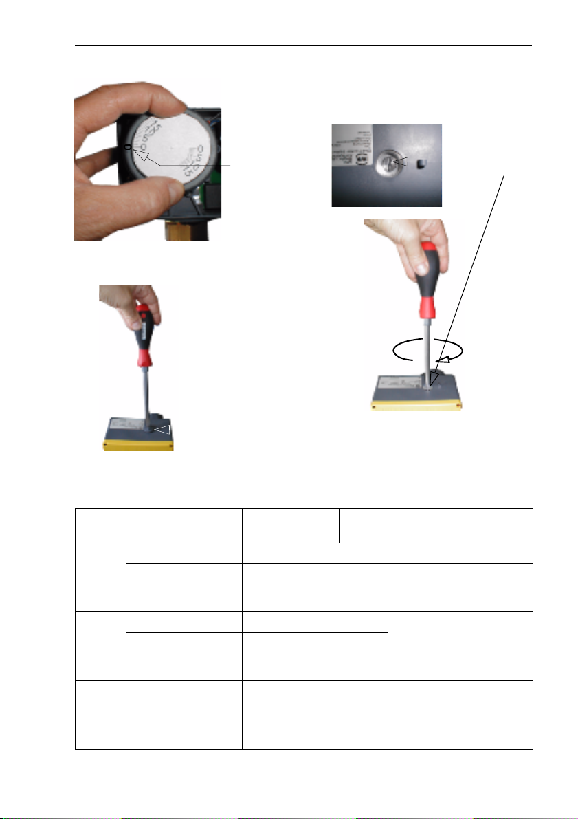
3. Adjust stroke indicator to 0.
adjust
4. Unscrew covering screw
1.
1
5. Turn stroke limiting screw
2 to
the right up to its stop.
2
➻➻➻➻ The stroke of the actuator is
set to 0 mm.
T1 Valve strokes VIM2, AIQM, VIS2, VIU2
Nom.
diam.
VIM2
AIQM
VIS2 Val ve
VIU2 Va lve
34
DN 15 20 25 32 40 50
Val ve
stroke
Turns of stroke
limiting screw
stroke
Turns of stroke
limiting screw
stroke
Turns of stroke
limiting screw
mm 8 10 15
6.5 8 12
mm 5
4
mm 5
> 5
Page 35

Mechanical Stroke Setting
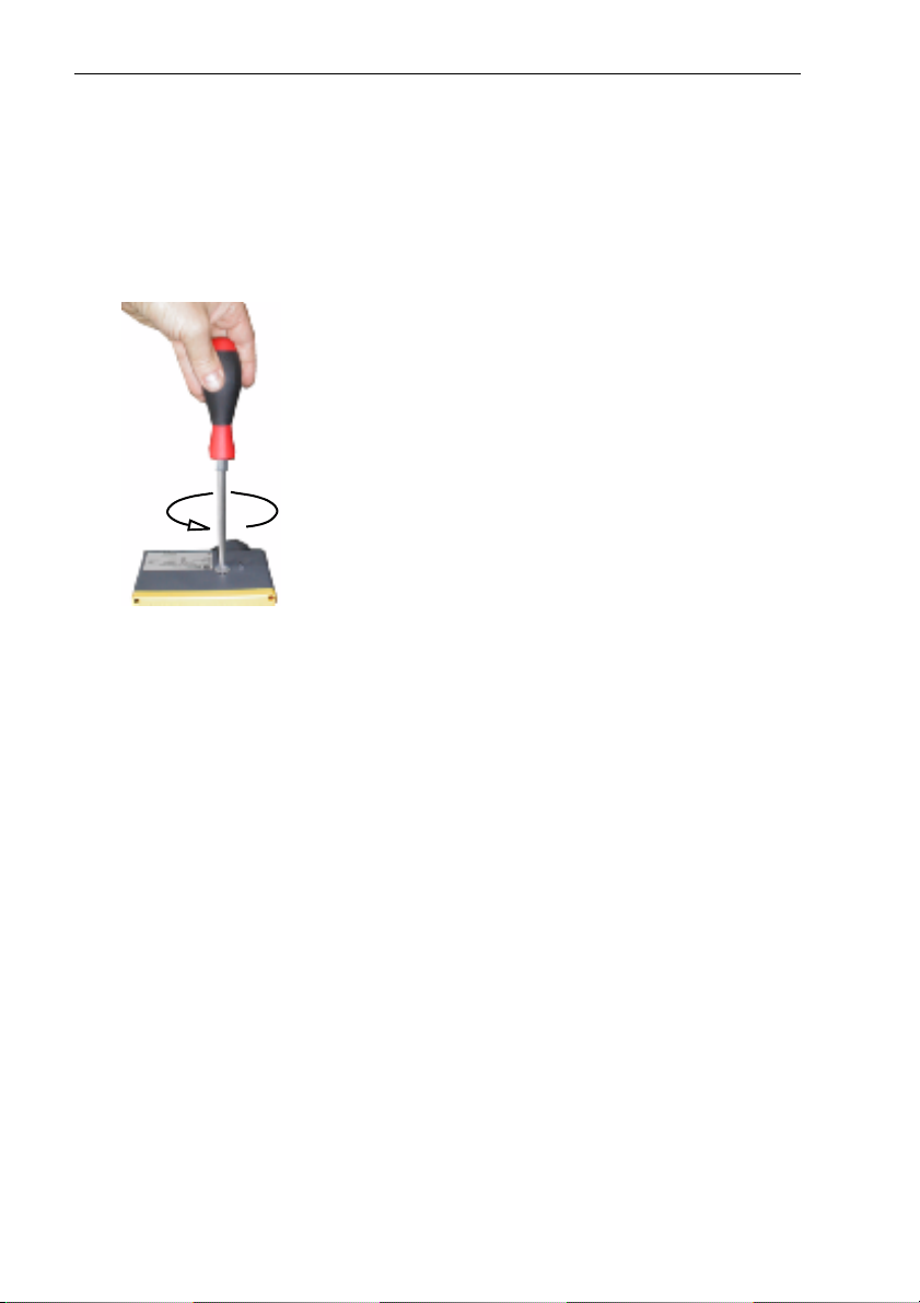
6. Read “Turns of stroke limiting
screw“ from table T1.
7. Unscrew stroke limiting screw
by this number of turns to the
left.
➻➻➻➻ The setting of the stroke is
completed.
8. Re-mount cover and covering
screw.
6.2 Valve AIQM5
At first, proceed as with valves
VIG2, see section 6.1.
In item 7, you must read the
number of necessary turns of the
stroke limiting screw from the setting curves (see section 6.3).
Example:
Valve DN 15, kvs = 1.6 m³/h
The flow rate is to be limited to
0.2 m³/h.
Procedure:
1. Choose diagram.
2. Read the number of turns of
the stroke limiting screw for
the flow rate of 0.2 m³/h:
3.5 turns.
3. Unscrew the stroke limiting
screw by this number of turns
(to the left).
35
Page 36

Mechanical Stroke Setting
0
5
0
4
6.3 Flow Adjusting Curves AIQM5
DN 15 Kvs 1,6 m³/h
0,7
0,6
0,5
0,4
Example
0,3
Beispiel
0,2
Flow (m³/h)
Volumenstrom (m³/h)
0,1
0
12 34 5 67
Umdrehungen
Turns of stroke limiting
Hubbegrenzungsschraube
screw
DN 15 Kvs 4 m³/h
2,5
2
1, 5
1
Flow (m³/h)
0,5
Volumenstrom (m³/h)
0
1234567
Umdrehungen
Turns of stroke limiting
Hubbegrenzungsschraube
screw
DN32 Kvs 12,5 m³/h
10
9
8
7
6
5
4
3
Flow (m³/h)
2
Volumenstrom (m³/h)
1
0
123456789101112
Umdrehungen
Turns of stroke limiting
screw
Hubbegrenzungsschraube
DN 15 Kvs 2,5 m³/h
1, 4
1, 2
1
0,8
0,6
0,4
Flow (m³/h)
Volumenstrom (m³/h)
0,2
0
1234567
Umdrehungen
Turns of stroke limiting
screw
Hubbegrenzungsschraube
DN 20 Kvs 6,3 m³/h / DN 25 Kvs 8 m³/h
5
Max. Volumenstrom DN 25
4,5
4
3,5
3
2,5
2
1, 5
Flow (m³/h)Flow (m³/h)
1
Volumenstrom (m³/h)
0,5
0
16
14
12
10
8
6
4
Volumenstrom (m³/h)
2
0
Max. Flow DN 50
x. Volumenstrom DN 2
Max. Flow DN 40
123456789
Turns of stroke limiting
Umdrehungen
screw
Hubbegrenzungsschraube
DN 40 Kvs 16 m³/h / DN 50 Kvs 20 m³/h
Max. Volumenstrom DN
Max. Flow DN 5
ax. Volumenstrom DN
Max. Flow DN 40
23456789101112
Umdrehungen
Turns of stroke limiting
screw
Hubbegrenzungsschraube
36
Page 37

Adjustments AME210, AME213
7 Adjustments AME210, AME213
Prior to commissioning, the input and output signals must be adjusted and
the end positions must be aligned.
7.1 Overview DIP switch settings
ON
ON
ON
OFF
1 2 3 4 5 6 7 8
1 Without function Without function
2 Input signal 4 - 20 mA
2 - 10 V
Input signal 0 - 20 mA
0 - 10 V
3 Output signal 2 - 10 V Output signal 0 - 10 V 7.3
47.4
Inverse operation
5
Automatic operation
6 Manual operation:
Extend stem
7 There is no new alignment of
the end positions
20 mA
10 V
0(2, 4)
0 Hub 100 %
Normal operation
1)
Manual operation 8.3
Manual operation:
Retract stem
When switching on the power supply, the stem is extended until the valve is
closed,
End position „Valve closed“
is re-aligned.
1 2 3 4 5 6 7 8
20 mA
10 V
0(2, 4)
0 Hub 100 %
see section
7.2
8.3
-
8 Fault indicator ON Fault indicator OFF 9.3
1)
During control operation, it is absolutely necessary to set switch to
automatic.
The switch positions 1, 6, 7, 8 have no influence on normal control
operation.
37
Page 38

Adjustments AME210, AME213
7.2 Input Signal Settings 7.3 Output Signal Settings
The output signal 0(2) - 10 V is proportional to the positioning stroke.
S1 S2
S1
S2
ON
1 2 3 4 5 6 7 8
Input
signal
0(4) - 20 mA
0(2) - 10 V
Offset
input signal
0 - 20 mA
0 - 10 V
S2
ON
1 2 3 4 5 6 7 8
ON
1 2 3 4 5 6 7 8
Offset output signal
0 - 10 V
2 - 10 V
ON
1 2 3 4 5 6 7 8
38
4 - 20 mA
2 - 10 V
Page 39

Adjustments AME210, AME213
7.4 Assignment of the effective direction to the input/output signal
Valves: VIM2, VIS2, AIQM
ON
S2
1 2 3 4 5 6 7 8
20 mA
10 V
Input,
output
signal
0(2-4)
0 Stroke 100 %
ON
S2
1 2 3 4 5 6 7 8
Input,
output
signal
Normal operation
Valve: VIU2
ON
S2
1 2 3 4 5 6 7 8
20 mA
10 V
0(2-4)
0 Stroke 100 %
ON
S2
1 2 3 4 5 6 7 8
20 mA
10 V
Input,
output
signal
0(2-4)
0 Stroke 100 %
Inverse operation
20 mA
10 V
Input,
output
signal
0(2-4)
0 Stroke 100 %
39
Page 40
Adjustments AME210, AME213
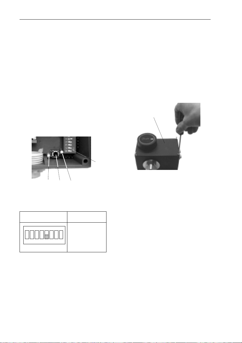
7.5 Setting the End Positions
After having completed the stroke
settings (see section 6), the end
positions “Valve open“ and “Valve
closed“ must be aligned with the
current and voltage values 0(4) 20 mA, 0(2) - 10 V.
1. Switch on voltage supply.
➻
➻ Green LED 1 must flash.
➻➻
Red LED
activated.
2 may flash or be de-
S2
3
1 2
During the alignment, the red
2 is flashing, in the end it
LED
will be deactivated.
The adjustments are
completed, the electrical actuator is in automatic
operation.
4. Re-mount cover
Philips screws.
4 and tighten
4
2. Set switch
S2:
S2
ON
Automatic
1 2 3 4 5 6 7 8
3. Briefly press push-button
operation
3.
➻➻➻➻ The actuator is opened and
closed several times; this
automatically aligns the end
positions.
40
Page 41

Manual Adjustment
8 Manual Adjustment
Prior to manual adjustment, disconnect voltage supply.
8.1 Actuator AMV210, AME210
Manual adjustment is performed
by turning the rotary switch:
l Retracting the stem of the
actuator
VIM2
VIS2
AIQM
VIU2
l Extending the stem of the
actuator
VIM2, VIS2,
AIQM
8.2 Actuator AMV213, AME213
After having dismounted the cover, you can perform the manual
adjustment by means of a hexagon socket screw key SW 4.
VIU2
1
Turning direction see section 8.1.
Block position with pin
1.
41
Page 42

Manual Adjustment
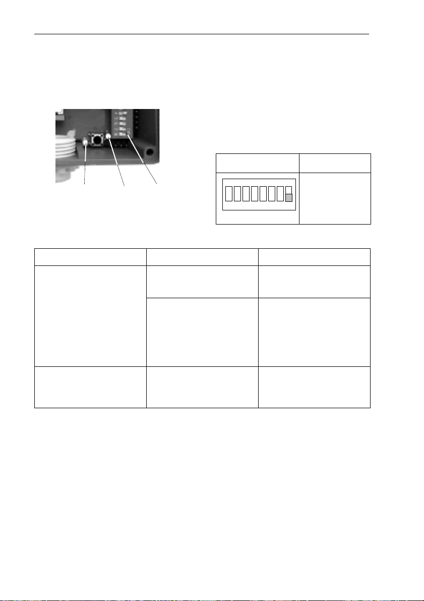
8.3 Actuator AME210, AME213
With these actuators, the manual
adjustment can be performed electrically when the cover has been
dismounted.
S2
3
l Retract stem of the actuator
l Extend stem of the actuator
VIM2
VIS2
VIU2
AIQM
by setting the switch S2
:
S2
ON
Extend
1 2 3 4 5 6 7 8
stem
and pressing the push-button
3.
VIM2
VIS2
VIU2
AIQM
by setting the switch S2:
S2
ON
Retract
1 2 3 4 5 6 7 8
stem
and pressing the push-button
3.
42
For control operation, it is absolutely necessary to set switch to
automatic:
S2
ON
Automatic
1 2 3 4 5 6 7 8
operation
Page 43

9 Troubleshooting
9.1 Fault, cause, remedy
Fault Possible cause Remedy
Troubleshooting
No function of the
actuators
Effective direction of
actuator is inverse.
Power is switched off. Check power connec-
tion.
No control signal of
the electrical control
unit.
Safety unit STB, STW
or SDB has
responded.
Mounting aid (pin) has
not been removed.
Actuator is defect. See also 9.2
Design AME2...:
DIP switch is set to
manual operation.
Design AMV2 ...:
connection at terminals 6 and 7 are exchanged, see section
5.4.
Design AME2...:
DIP switch is set to
inverse operation.
Check control unit.
Check system and
safety unit.
Remove mounting
aid, see section 5.2
item 4.
Set switch to
automatic, see section
7.1, switch 5.
Change terminal con-
nection.
Set switch to normal
operation, see section
7.4.
43
Page 44
Troubleshooting
9.2 Fault Indicator
Actuators AME210, 213
A fault can be indicated by:
1. LEDs
1 and 2
2. Output signal > 11 V
(terminals 7 (+) and 5),
if switch
position:
S2 has the following
S2
ON
1 2
Fault indicator Fault Remedy
Output signal >11V
and
Red LED
approx. 2.5 times per
second.
Green LED
light up.
2
is flashing,
1
does not
S2
1 2 3 4 5 6 7 8
Actuator defect
or
Valve stem is blocked,
i.e. actuator cannot
travel to position.
Voltage supply is interrupted.
Replace actuator.
Check valve.
Is the valve stem
mobile?
Replace valve if
necessary.
Check voltage supply
and electrical connection.
Fault
indicator
>11 V ON
44
Page 45

Troubleshooting
45
Page 46

Danfoss IWK Regler GmbH
Postfach 1121, D-76288 Stutensee
Lorenzstraße, D-76297 Stutensee
Tel.: +49 (0) 0 72 44 / 7205-0
Fax.: +49 (0) 0 72 44 / 7205- 311
E-mail: DEBC0043@danfoss.com
www.iwk.danfoss.de
 Loading...