

Page 1
Data sheet
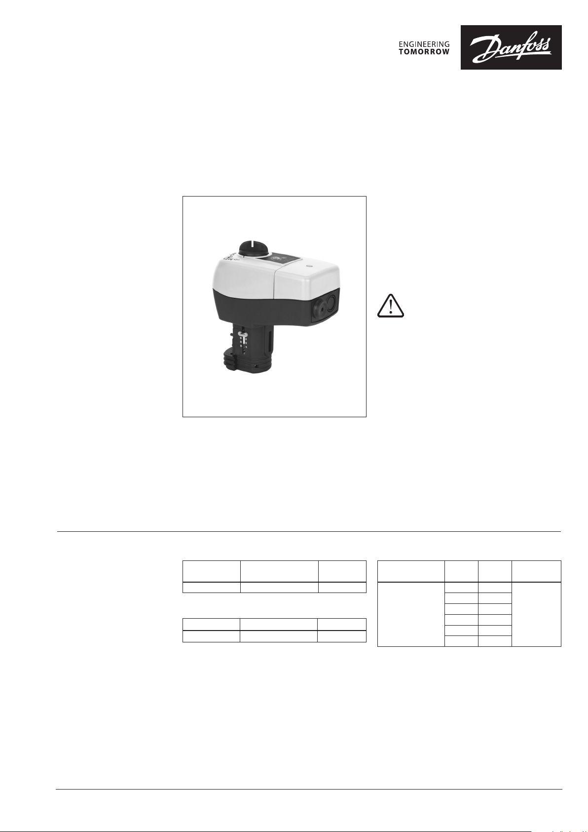
Actuator for modulating control
AME 445 - for industrial applications
Description
AME 445 actuator is used for industrial applications
with two and three-way valves type VRB, VRG, VF
and VL up to DN 80 diameter.
The actuator has some special features:
• it automatically adapts its stroke to the valve
end positions which reduces commissioning
time (self stroking)
• valve flow adjustment feature; flow can be
variably-adjusted from linear to logarithmic or
opposite.
• the advanced design incorporates load
related ‘switch-off’ to ensure that actuators
and valves are not exposed to overload
Combinations with other valves could be seen
under Accessories.
Not appropriate for domestic applications, for hot water
servi ce with heat exc hangers and f or applicati ons where
higher noise level is not acceptable.
Main data:
• Nominal voltage (AC or DC):
• 24 V, 50/60 Hz
• Control input signal:
• 0(4)-20 mA
• 0(2)-10 V
• Force: 400 N
• Stroke: 20 mm
• Speed: 3 s/mm
• Max. medium temperature: 130 °C
• Self stroking
• LED signalling
• External RESET button with lock option
• Output signal
• Manual operation
Ordering
© Danfoss | 2016.08
Actuator
Typ e
AME 445 24 AC/DC 082H0 053
Power supply
(V)
Accessories - Stem heater
Typ e DN Code No.
Stem heater 15 -80 065Z 0315
Code No.
Accessories - Adapter
Valves DN
Adapter for old
VRB, VRG, VF, VL
valves
max. Δp
(bar)
15 9
20 4
25 2
32 1
40 0.8
50 0.5
Code No.
06 5Z0313
VD.LF.P3.02 | 1
Page 2
Data sheet Actuator for modulating control AME 445
Technical data
Installation
Power supply V 24 AC/DC; ±10%
Power consumption VA 7.6
Frequency Hz 50/60
Control input Y
Output signal X V 0-10 (2-10); [RL = 650 Ω] (maximal load)
Close of force N 400
Max. stroke mm 20
Speed s/mm 3
Max. medium temperature
Ambient temperature 0 … 55
Storage and transport temperature –40 … 70
Protection class II
Grade of enclosure IP 54
Weight kg 0.45
- marking in accordance with standards
V
mA
°C
Low Voltage Directive (LVD) 2006/95/EC: EN 60730-1, EN 60730-2-14
EMC Directive 2004/108/EC: EN 61000- 6-2, EN 61000 -6-3
0-10 (2-10); [Ri = 95 k Ω]
0-20 (4-20); [Ri = 500 Ω]
130
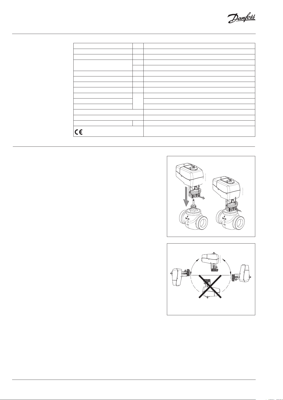
Mechanical
No tool is required to mount actuator on the
valve. Installation of the valve with the actuator
is allowed in horizontal position or upwards.
Installation downwards is not allowed.
The actuator must not be installed in an
③
①
②
explosive atmosphere, at ambient temperature
lower than 0 °C or at ambient temperature higher
than 55 °C. It must not be subject to steam jets,
water jets or dripping liquid as well.
⑤
④
Note:
The actuato r may be rotated up to 360° with respe ct to the valve
stem by looseni ng the retaining fixtur e. Once the actuator is
placed, retighten the fixture.
Electrical
Electrical connections can be accessed by
removing the actuator cover. Two cable gland
entries without thread (Ø 16 and combined
Ø 16/Ø 20) are prepared for cable glands. From
factory one entry is provided by rubber cable
gland and the other entry is prepared for
opening.
Note:
Cable and cable g land used must not compromise the a ctuator’s
IP rating, and must e nsure the connectors are ful ly strain relieved.
Rubber cabl e gland delivered from fac tory does not compromis e
IP rating but it doe s not provide fully strain rel ieve according to
LVD directive.
Please obser ve local rules and regulatio ns as well.
2 | © Danfoss | 2016.08
VD.LF.P3.02
Page 3
Data sheet Actuator for modulating control AME 445
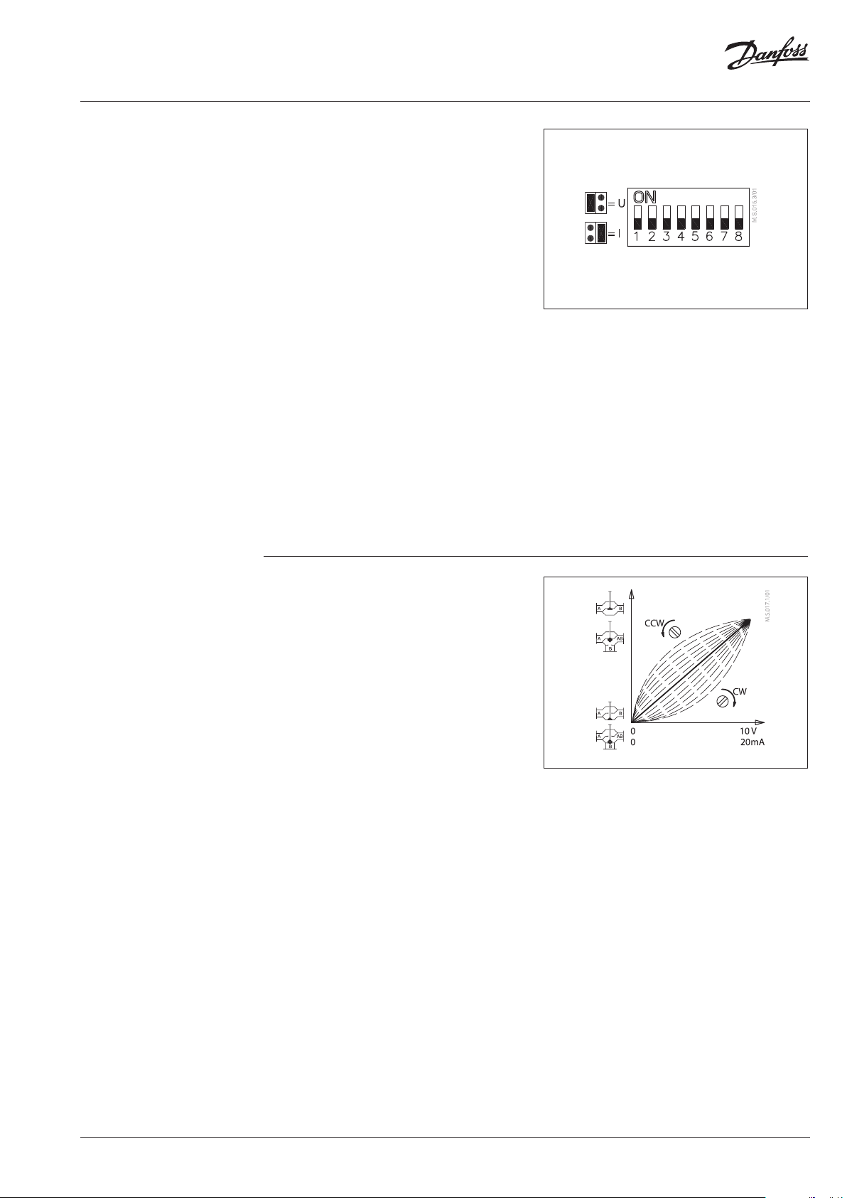
Jumper/DIP switch setting
Jumper
• U/I - Input signal type selector
• U position; voltage input is selected
• I position; current input is selected
DIP switches
• SW 1: Not used
• SW 2: Input signal range selector
• OFF position; the input signal is in the range
from 0-10 V (voltage input) or from 0-20 mA
(current input)
• ON position; the input signal is in the range
from 2-10 V (voltage input) or from 4-20 mA
(current input)
• SW 3: Direct or inverse acting selector
• OFF position; the actuator is in direct acting
mode (stem extend as voltage increases)
• ON position; the actuator is in inverse acting
mode (stem retracts as voltage increases)
• SW 4: Not used
• SW 5: Not used
• SW 6: Not used
INV
2 … 10 V
DIR
0 … 10 V
LOG
SMART
LIN
ACT
• SW 7: Linear or equal-percentage flow
through valve selector
• OFF position; the valve position is linear acc.
to the control signal
• ON position; the valve position is equalpercentage acc. to the control signal. This
relation is adjustable - see Equal-percentage
valve-flow adjustment section
• SW 8: Smart function selector
• OFF position; the actuator does not try to
detect oscillations in the system
• ON position; the actuator enables special anti
oscillations algorithm – see Anti oscillations
algorithm section
Equal-percentage valve-flow adjustment
(SW 7 in position ON)
The actuator has a special valve-flow
adjustment feature. Flow can be, by turning
the potentiometer clock wise (CW) or counter
clockwise (CCW), variably adjusted from linear
to logarithmic or opposite. For details see
Instructions.
VD.LF.P3.02
© Danfoss | 2016.08 | 3
Page 4
Data sheet Actuator for modulating control AME 445
Jumper/DIP switch setting
(continued)
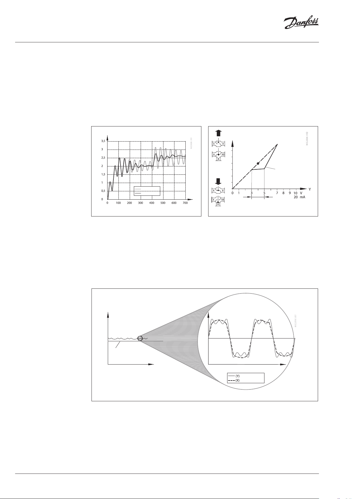
Anti oscillations algorithm
(SW 8 in position ON)
The actuator has special anti oscillations
algorithm. In case control signal Y on certain
point oscillates (Fig. 1) - looking from time
perspective, algorithm starts to lower the
amplification of the output to the valve. Instead
of having static characteristics actuator changes
to dynamic characteristics (Fig. 2) - certain
output stroke area changes to new slope
(decrease amplification).
Valve position X signal (V)
Functi on OFF
Functi on ON
Fig. 1
time (se c)
iMCV 2nd generation
Harmonic oscillations are high frequency
oscillations with low amplitude that vary around
its own equilibrium value and not around
set-point temperature. They can appear in up to
70 % of control time, even though the system is
properly commissioned. Harmonic oscillations
have negative influence on control stability, and
lifetime of the valve and actuator.
After control signal does not oscillate anymore
output to the valve slowly returns back to static
characteristics.
Stroke
static characteristic
Point A
linear area
Fig. 2
dynamic
characteristic
Smoothening function
Smoothening function implemented in New 2nd
generation of anti-oscillation function reduces
harmonic oscillations; consequently room
temperature is closer to the set-point (desired)
temperature. Smoother operation of the MCV
increases lifetime of the valve and actuator and
saves energy and reduces costs in general.
4 | © Danfoss | 2016.08
temperature
set-point
time (24 h) time (1 h)
temperature
set-point
control signal
feedback signal
VD.LF.P3.02
Page 5

Data sheet Actuator for modulating control AME 445
Commissioning
Complete the mechanical and electrical
installation, set jumper and DIP-switches, then
perform the necessary checks and tests:
• Apply power
Note that the actuator will now perform
automatic self stroking function
• Apply the appropriate control signal and
check:
• if the valve stem direction is correct for the
application and
• the actuator drives the valve over the entire
stroke length
The unit is now fully commissioned.
Automatic self stroking feature
The actuator automatically adapts its stroke to
the valve end positions:
• when power is applied for the first time or
• afterwards by pressing the STAND-BY/
RESET/LOCK-button button for 6-9 seconds.
The function gets active with releasing the
button after 2 × green LED blinks. If LOCK
MODE is activated (indicated by 1 × red LED
blink after 3 sec. and 2 × after 6 sec.) please
first unlock the button-functions by pressing
the button for 9-12 sec. and releasing it after
3 × green LED blinks. The button-functions
are unlocked now and RESET MODE can be
activated as mentioned before.
Testing entire valve stroke length
The actuator can be driven to the fully-open or
closed positions (depending on valve type) by
connecting SN to terminals 1 or 3.
VD.LF.P3.02
© Danfoss | 2016.08 | 5
Page 6
Data sheet Actuator for modulating control AME 445
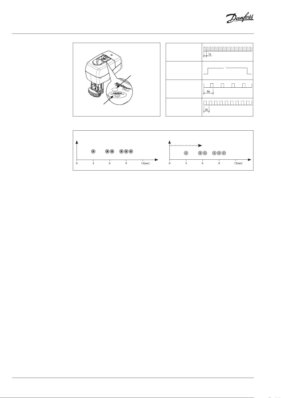
LED signalling/
Actuator operating modes
Flashing green LED:
Self stroking mode =
RESET MODE
(period is every second)
Constant green LED:
POSITIONING MODE
Flashing green LED:
Setpoint is reached
(period is every
Flashing red LED:
STAND-BY MODE
(period is every two
STA ND-B Y/RE SET/
LOCK- butto n
RED / GREEN
LED LIGHT
STAND-BY, RESET and LOCK MODE on actuator AME 445
Starting from NORMAL MODE
STAN D- BY
enabled
1 × Green 2 × Green 3 × Red
RESET
enabled
LED function indicator
LOCK MODE
activatedNoactivation
Starting from LOCK MODE
LOCK MODE is st ill activated
• STAND-BY MODE
Pressing the STAND-BY/RESET/LOCK-button
The bicolour (green/red) LED function indicator
is located on the actuator cover. It indicates the
operating modes.
for 3-6 sec. and releasing it after 1 × green
LED blink causes the actuator to activate
STAND-BY MODE. The actuator will not react
on any change of the control signal until it is
External button
switched back again to NORMAL MODE by
pressing the button as mentioned before.
Actuator has external STAND-BY/RESET/
LOCK-button which is located next to LED
indicator.
By pressing, holding and releasing this button
for/after specified time periods, different
operating modes are initiated:
During STAND-BY MODE, the actuator can be
moved manually or can be switched to RESET
MODE or LOCK MODE by pressing the button
as described in the according operating
modes.
• LOCK MODE
• Self stroking mode = RESET MODE
Pressing the STAND-BY/RESET/LOCK-button
for 6-9 sec. and releasing it after 2 × green LED
blinks causes the actuator to start
self stroking procedure:
The bicolor LED flashes green at 1 sec.
intervals during calibration procedure, which
begins by extending the stem. When the
maximum force is detected (at the valve
end position), the actuator then retracts the
stem, until the maximum force is once again
detected (on the other valve end position).
The actuator will then enter to NORMAL MODE
Pressing the STAND-BY/RESET/LOCK-button
for 9-12 sec. and releasing it after 3 × red LED
blinks causes the actuator to activate LOCK
MODE. The actuator can not be brought to
STAND-BY MODE or RESET MODE until it was
switched back again to NORMAL MODE by
pressing the button as mentioned before
(releasing the button now after 3 × green
LED blinks). During LOCK MODE, the actuator
works just as described in NORMAL or
POSITIONING MODE, but with partly locked
button-functions (shown with 1 × or 2 × red
LED blinks).
and respond to the control signal.
• REMARK
• POSITIONING MODE
The bicolour LED is green and stays on during
positioning of the actuator according to the
Pressing the STAND-BY/RESET/LOCK-button
for more than 12 sec., no activation/
deactivation occurs.
control signal
6 seconds)
seconds)
1 × Red 2 × Red
Deactivates
LOCK MODE
3 × Green
≈
activat ion /
deactivation
No
6 | © Danfoss | 2016.08
• NORMAL MODE
When the positioning of the actuator is
finished the LED flashes green every 6
seconds.
VD.LF.P3.02
Page 7
Data sheet Actuator for modulating control AME 445
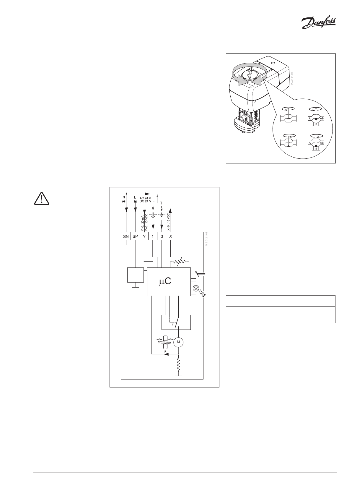
Manual override
Wiring
24 V AC/DC only
Manual override is done by means of control
knob on actuator housing:
• Disconnect power supply or activate
STAND-BY MODE
• Adjust valve position using the control knob
(observe the rotation direction)
After manual override is not needed:
• Restore power supply or go to NORMAL
MODE again
Remark:
When the manua l override has been used, the o utput signal (X) is
not correct unti l the actuator reaches its e nd position.
SP 24 V AC/DC ...... Power supply
power
supply
down up
SN 0 V .............. Common
Y 0(2)-10 V ......... Input signal
0(4)-20 mA
X 0(2) -10 V ......... Output signal
1, 3 Override input signal
(can not be used for 3-point control)
Wiring length
0-50 m 0.75 mm
> 50 m 1.5 m m
Recommended cross-sectional
area of the wiring
2
2
Disposal
VD.LF.P3.02
The actuator must be dismantled and the
elements sorted into various material groups
before disposal.
© Danfoss | 2016.08 | 7
Page 8

Danf
already on order pro
All trademarks in this material are property of the respec
Data sheet Actuator for modulating control AME 445
Actuator - valve
combinations
Dimensions
AME 445 +
VRB 2, VRG 2
147
AME 445 +
VRB 3, VRG 3
AME 445 +
VF 2, VL 2
DN 15- 80
82.5
159. 5
AME 445 +
VF 3, VL 3
DN 15- 80
min . 180
oss can accept no responsibility for possible errors in catalogues, brochures and other printed material. Danfoss reserves the right to alter its products without notice. This also applies to products
vided that such alterations can be made without subsequential changes being necessary eady agreed.
8 | © Danfoss | DHS-SRMT/SI | 2016.08
tive companies. Danfoss and the Danfoss logotype are trademarks of Danfoss A/S. All rights reserved.
VD.LF.P3.02
 Loading...