

Page 1

Operating Guide
AME 445
AME 445 + AME 445 + AME 445 + AME 445 +
VRB 2, VRG 2 VRB 3, VRG 3 VF 2, VL 2 VF 3, VL 3
ENGLISH
DEUTCH
AME 445 www.danfoss.com Page 6
AME 445 www.danfoss.de Seite 7
© Danfoss | 2016.09
VI.LF.E3.5B | 1
Page 2

AME 445
❶
MAINTENANCE
FREE
①
5-95 % RH
no condensing
4 – 6 mm × 1 mm
⑥
③
③
③
②
②
⑤
Click
④
⑥
⑤
④
2 | © Danfoss | 2016.09
VI.LF.E3.5B
Page 3

AME 445
❷
❸
②
①
3-6 sec =
①
STA ND BY−OFF
STA ND BY−ON
②
③
LED: red
❹
④
⑤
①
6-9 sec = RESET
LED: green
③
➎
Flashing green LED:
Self str oking mode = RESE T MODE
(perio d is every second )
Constant g reen LED:
Positioning mode
Flashing green LED:
Setpoi nt is reached (per iod is every
6 seconds)
Flashing re d LED: STAND BY mode
(perio d is every two seco nds)
Grüne LED b linkt: automat ische
Hubanpassung (Intervall
Sekunde)
Dauerhaft grün leuchtende LED:
Positionierungsmodus
Grüne LED b linkt: Sollwe rtposition
erreicht (Intervall = alle 6 Sekunden)
= jede
STAND BY, RESET and LOCK MODE on actuator AME 445
Starting from NORMAL MODE
≈
Starting from LOCK MODE
STAND BY, RESET und LOCK-MODUS auf Stellantrieb AME 445
Start aus dem NORMAL-MODUS
≈
Start aus dem LOCK-MODUS
Rote LED bli nkt: STAND BY Modus
(Intervall = alle 2 Sekunden)
VI.LF.E3.5B
© Danfoss | 2016.09 | 3
Page 4
AME 445
➏
100% / FULL!
①
Click
②
~ 60°
➐
ON
OFF
②
⑤
⑧
⑥
⑦
③
①
4 | © Danfoss | 2016.09
VI.LF.E3.5B
Page 5

AME 445
➑
VI.LF.E3.5B
© Danfoss | 2016.09 | 5
Page 6
AME 445
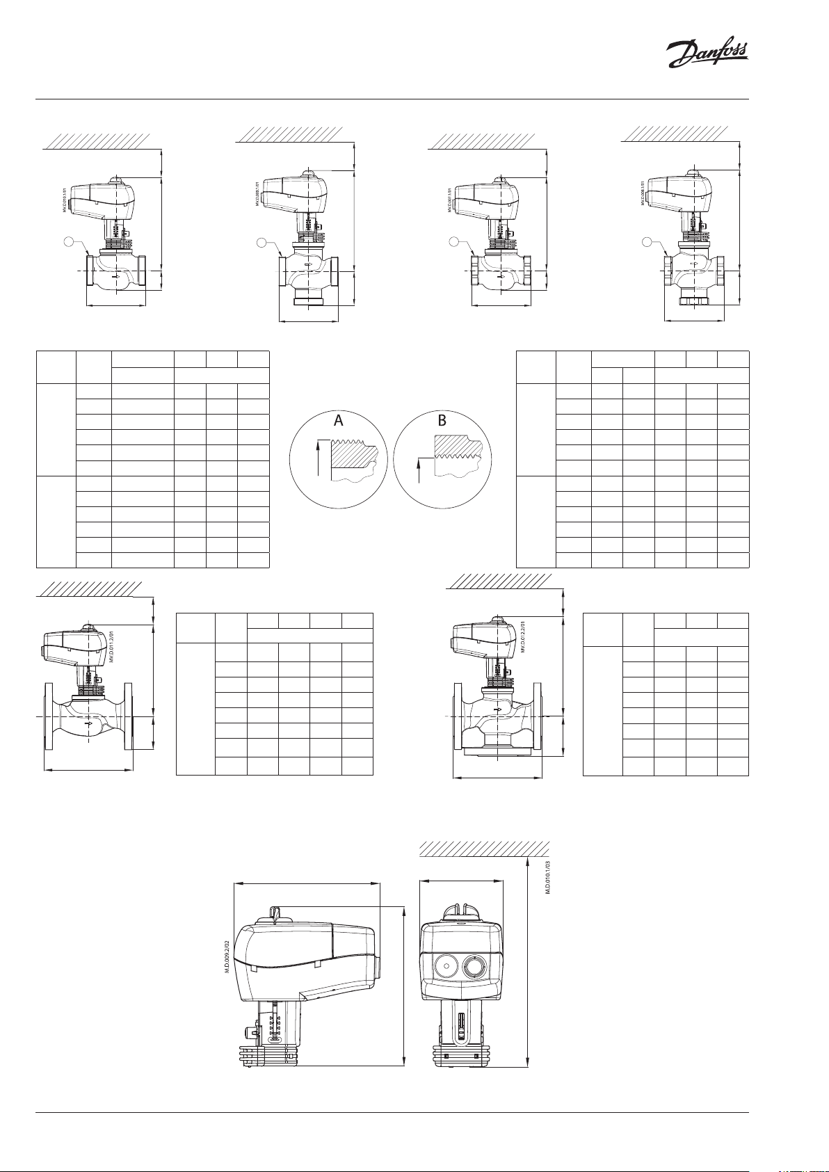
➒
Min 20,5
Min 20,5
Min 20,5
Min 20,5
A
AME 445 + VR B 2, VRG 2
Typ e DN
15 1 80 29 191
20 1⁄ 80 31 193
VRG 2
25 1⁄ 95 32 197
32 2 112 35 201
40 2⁄ 132 45 213
50 2 ¾ 160 48 217
15 1 80 40 191
20 1⁄ 80 45 193
VRG 3
25 1⁄ 95 50 196
32 2 112 58 201
40 2⁄ 132 75 230
50 2 ¾ 160 83 243
L
AME 445 +
VF 2, VL 2 (DN 15- 80)
1
H
H
L
Connection L H H
G mm
min. 20,5
Typ e DN
15 130 47, 5 40 191
1
H
20 150 52,5 45 194
25 160 57,5 50 19 7
32 180 70 60 202
VF 2
VL 3
40 200 75 65 213
50 230 82,5 70 218
H
65 290 92,5 88 254
80 310 100 95 258
A
L
AME 445 + VR B 3, VRG 3
1
G
L HVFHVLH1
mm
1
H
B
H
L
1
H
B
H
1
H
H
L
AME 445 + VR B 2
Typ e DN
Connection L H H
Rp G mm
AME 445 + VR B 3
1
15 ½ 1 80 25 191
20 ¾ 1⁄ 80 29 194
VRB 2
25 1 1⁄ 95 29 197
32 1⁄ 2 112 33 202
40 1⁄ 2⁄ 132 43 213
P
R
50 2 2 ¾ 160 47 217
15 ½ 1 80 40 191
20 ¾ 1⁄ 80 45 19 4
VRB 3
25 1 1⁄ 95 50 197
32 1⁄ 2 112 58 202
40 1⁄ 2⁄ 132 75 230
50 2 2 ¾ 160 83 243
min. 20,5
L H H1
mm
15 130 63 191
20 150 70 194
1
H
Typ e DN
25 160 75 197
32 180 80 202
VF 3
40 200 90 230
VL 3
H
50 230 100 243
65 290 120 254
L
AME 445 +
VF 3, VL 3 (DN 15-8 0)
80 310 155 270
6 | © Danfoss | 2016.09
147
82,5
min . 180
159, 5
VI.LF.E3.5B
Page 7

AME 445
ENGLISH
Safety Note
To avoid injury of persons and
damages to the device, it is absolutely
necessary to read and observe these
instructions carefully.
Necessary assembly, start-up, and maintenance
work must be performed by qualified and
authorized personnel only.
Please comply with the instructions of the
system manufacturer or system operator.
Do not remove the cover before th e
power supply is ful ly switched off.
Disposal instruction
This product should be dismantled
and its components so rted, if possible,
in various groups befo re recycling or
disposal.
Always follow the local d isposal regulations.
Mounting and installation ❶
Wiring ❷
Do not touch anything on the
PCB!
Switch off the power line before wiring the
actuator! Lethal voltage!
Wire the actuator according to the wiring
diagram.
Functions accessible from cover
STAND BY MODE ❸
Pressing the STAND BY/RESET/LOCK button
for 3-6 sec. and releasing it after 1x green LED
blink causes the actuator to activate STAND
BY MODE. The actuator will not react on any
change of the control signal until it is switched
back again to NORMAL MODE by pressing the
button as mentioned before. During STAND BY
MODE, the actuator can be moved manually
or can be switched to RESET MODE or LOCK
MODE by pressing the button as described in the
according operating modes.
LOCK MODE
Pressing the STAND BY/RESET/LOCK button for
9-12 sec. and releasing it after 3x red LED blinks
causes the actuator to activate LOCK MODE. The
actuator can not be brought to STAND BY MODE
or RESET MODE until it was switched back again
to NORMAL MODE by pressing the button as
mentioned before (releasing the button now
after 3× green LED blinks). During LOCK MODE,
the actuator works just as described in normal
or positioning mode, but with partly locked
button-functions (shown with 1x or 2× red LED
blinks).
Self stroking mode = RESET MODE ❹
Pressing the STAND BY / RESET / LOCK but ton
for 6-9 sec. and releasing it after 2× green LED
blinks causes the actuator to start self stroking
procedure:
The bi-colour LED flashes green at 1 sec. intervals
during calibration procedure, which begins by
extracting the stem. When the maximum force is
detected (at the valve end position), the actuator
then retracts the stem, until the maximum force
is once again detected (on the other valve end
position). The actuator will then automatically
enter to NORMAL MODE and respond to the
control signal.
Positioning mode
The bi-colour LED is green and stays on during
positioning of the actuator according to the
control signal
Normal mode
When the positioning of the actuator is finished
the LED flashes green every 6 seconds.
REMARK
Pressing the STAND BY/RESET/LOCK button for
more than 12 sec., no activation/deactivation
occures.
Manual override
NOTE: If manual override has been used then
control and return signal are not correct
until the actuator reaches its end position.
LED function indicator ➎
Green – initialization (RESET), set-point position,
transition indicator
Red - indicates STAND BY and Failure mode.
Green:
• Flashing light (once every 6 sec.)
- actuator reached set-point acc. to Y signal
• No light
- no operation or no power supply
• Flashing light (~ 1Hz)
- self adjusting mode.
Red:
• No light
- no operation or no power supply
• Constant light
- fault condition occurred
• Flashing light (2 Hz)
- STAND BY
- power supply too low
- initial self-adjusting time too short due to
too short valve strokes
- failure during self calibration.
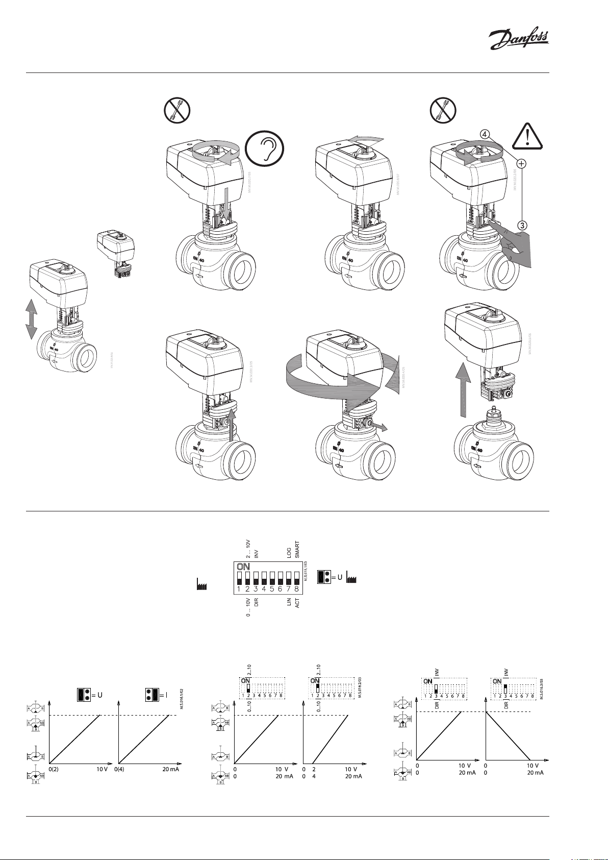
Dismounting ❻
Jumper / DIP switch settings ❼
Jumper ①: U/I - Input signal type selector
DIP switches
Factory settings:
ALL switches are in OFF position. The jumper is set
to “U”.
NOTE: All combinations of DIP switches are
allowed. All functions that are selected are added
consecutively.
SW 1: Not used
SW 2: 0/10 - Input signal range selector ②
SW 3: D/I - Direct or inverse acting selector ③
SW 4: Not used
SW 5: Not used
SW 6: Not used
SW 7: LIN/LOG - Linear or logarithmic flow
characteristic ❽
SW 8: Smart function selector
If set on ON position the actuator enables
special anti oscillations algorithm.
If set on OFF position the actuator does not try to
detect any oscillations in the system.
Dimensions ➒
7 | © Danfoss | 2016.09
VI.LF.E3.5B
Page 8

Danf
already on order pro
All trademarks in this material are property of the respec
AME 445
DEUTCH
Sicherheitshinweise
Um Verletzungen an Personen und
Schäden am Gerät zu vermeiden, ist
beachten.
Montage, Inbetriebnahme und
Wartungsarbeiten dürfen nur von sachkundigen
und autorisierten Personen durchgeführt
werden.
Die Vorgaben des Anlagenherstellers und
Anlagenbetreibers sind zu beachten.
diese Anleitung unbedingt zu
Gehäuse nicht öffnen, bevor die
Spannungsversorgung komplett
ausgeschaltet ist.
Entsorgungshinweise
Vor der Entsorgung ist der Stellantrieb
zu zerlegen. Die einzelnen
Komponenten sind dann, nach
Die örtliche n Entsorgungsbestimmungen sind
zu beachten.
Werkstoffen getrennt, zu entsorgen.
Montage ❶
Verdrahtung ❷
Keine Bauteile auf der Leiterplatte
berühren.
dem Anschließen
ausschalten. Tödliche Spannung.
Anschluss dem Schaltplan entsprechend
vornehmen.
Verstellbare Funktionen auf der
Abdeckung
STAND BY-MODUS ❸
Durch Drücken der STAND BY-/RESET-/LOCK
für 3-6 Sek. und Loslassen nach 1x Blinken der
grünen LED wechselt der Stellantrieb in den
STAND BY-MODUS. Der Stellantrieb reagiert
nicht auf Veränderungen des Kontrollsignals,
bis er durch Drücken der Taste (s. o.) wieder in
den NORMAL-MODUS geschaltet wird. Während
des STAND BY-MODUS kann der Stellantrieb
manuell bewegt oder durch Drücken der Taste
(s. entsprechende Betriebsmodi) in den RESETMODUS oder den LOCK-MODUS geschaltet werden.
Spannungsversorgung vor
des Stellantriebes
-Taste
LOCK-MODUS- Tastensperre
Durch Drücken der STAND BY-/RESET-/LOCKfür 9-12 Sek. und Loslassen nach 3x Blinken der
roten LED wechselt der Stellantrieb in den
LOCK-MODUS. Der Stellantrieb kann nicht in den
STAND BY- oder den RESET-MODUS geschaltet
werden, bevor er durch Drücken der Taste (s. oben:
Loslassen der Taste nach 3x Blinken der grünen
LED) in den NORMAL-MODUS geschaltet wurde.
Im LOCK-MODUS funktioniert der Stellantrieb wie
beim Normal- oder Positionierungsmodus
beschrieben, allerdings mit teilweise gesperrten
Tastenfunktionen (angezeigt durch 1x oder 2x
Blinken der roten LED).
Automatische Hubanpassung =
RESET-MODUS ❹
Durch Drücken der STAND BY-/RESET-/LOCK-Taste
für 6-9 Sek. und Loslassen nach 2x Blinken
der grünen LED beginnt der Stellantrieb die
automatische Hubanpassung:
Die zweifarbige LED blinkt während des
Kalibriervorgangs, der mit dem Ausfahren
der Antriebsstange beginnt, in 1-SekundenIntervallen grün. Wenn die maximale Kraft
erkannt wird (in der Ventilendlage), fährt der
Stellantrieb die Antriebsstange wieder ein, bis
erneut die maximale Kraft festgestellt wird
(in der anderen Ventilendlage).
Der Stellantrieb wechselt dann automatisch in
den NORMAL-MODUS und reagiert auf das
Kontrollsignal.
Positionierungsmodus
Die zweifarbige LED leuchtet grün und bleibt
während der Positionierung des Stellantriebs
entsprechend dem Kontrollsignal an.
Normalbetrieb
Nach abgeschlossener Positionierung des
Stellantriebs blinkt die grüne LED alle 6 Sekunden.
ANMERKUNG
Bei Gedrückthalten der STAND BY-/RESET-/
LOCK-Taste für mehr als 12 Sek. findet keine
Aktivierung/Deaktivierung statt.
Taste
Manueller Betrieb
Hinweis:
Wenn die Handverstellung vorgenommen wurde,
ist das Ausgangssignal (x) erst dann wieder korrekt,
wenn der Stellantrieb seine Endposition erreicht hat.
LED - Funktionshinweise ➎
Grün – Initialisierung (RESET), Sollwertposition,
Positionen Rot - Zeigt STAND BY und Fehlermodus an.
Grüne Diode :
• Blinkt (einmal alle 6 Sekunden)
- Stellantrieb erreicht Sollposition gemäß
Y-Signal
• Aus
- kein Betrieb oder keine
Spannungsversorgung
• Blinkt (mit ~1 Hz)
- Durchführen der automatischen
Hubanpassung
Rote Diode
• Aus
- kein Betrieb oder keine
Spannungsversorgung
• Ein
- Es ist eine Störung aufgetreten.
• Blinkt (mit 2 Hz)
- STANDBY-Modus
- Versorgungsspannung zu gering
- Zeit für die automatische Hubanpassung
zu kurz wegen zu kurzem Ventilhub
- Fehler während der automatischen
Hubeinstellung
Demontage
Steckbrücke / Einstellung DIP
Schalter ❼
Brücke ①: Auswahl des U/I - Eingangssignales
DIP Schalter
Werkseinstellungen:
Alle Schalter befinden sich in
Hinweis:
Alle Kombinationen der DIP Schalter sind erlaubt.
Die gewählten Funktionen liegen hintereinander.
der Position OFF.
SW 1: Nicht verwendet
SW 2: 0/10 -Wahlschalter für den
Signalbereich
(abhängig von der
gewählten Signalart) ②
SW 3: D/I – direkte oder (inverse)
entgegengesetzte Wirkrichtung ③
SW 4: Nicht verwendet
SW 5: Nicht verwendet
SW 6: Nicht verwendet
SW 7: LIN/LOG - Wahlschalter für die
Art der Kennlinie (linear oder
gleichprozentig (LOG)) ❽
SW 8:
Wahlschalter für die
Anti-Oszillationsfunktion.
- In Stellung OFF ist die Funkion deaktiviert,
d.h. der Stellantrieb versucht nicht,
Schwingungen in der Anlage
auszugleichen.
- In Stellung ON arbeitet der Stellantrieb mit
einem besonderen Algorithmus, der das
Schingen der Anlage verhindert.
Abmessungen ➒
oss can accept no responsibility for possible errors in catalogues, brochures and other printed material. Danfoss reserves the right to alter its products without notice. This also applies to products
vided that such alterations can be made without subsequential changes being necessary eady agreed.
8 | © Danfoss | DHS-SRMT/SI | 2016.09
tive companies. Danfoss and the Danfoss logotype are trademarks of Danfoss A/S. All rights reserved.
73691480/VI.LF.E3.5B
 Loading...