

Data sheet
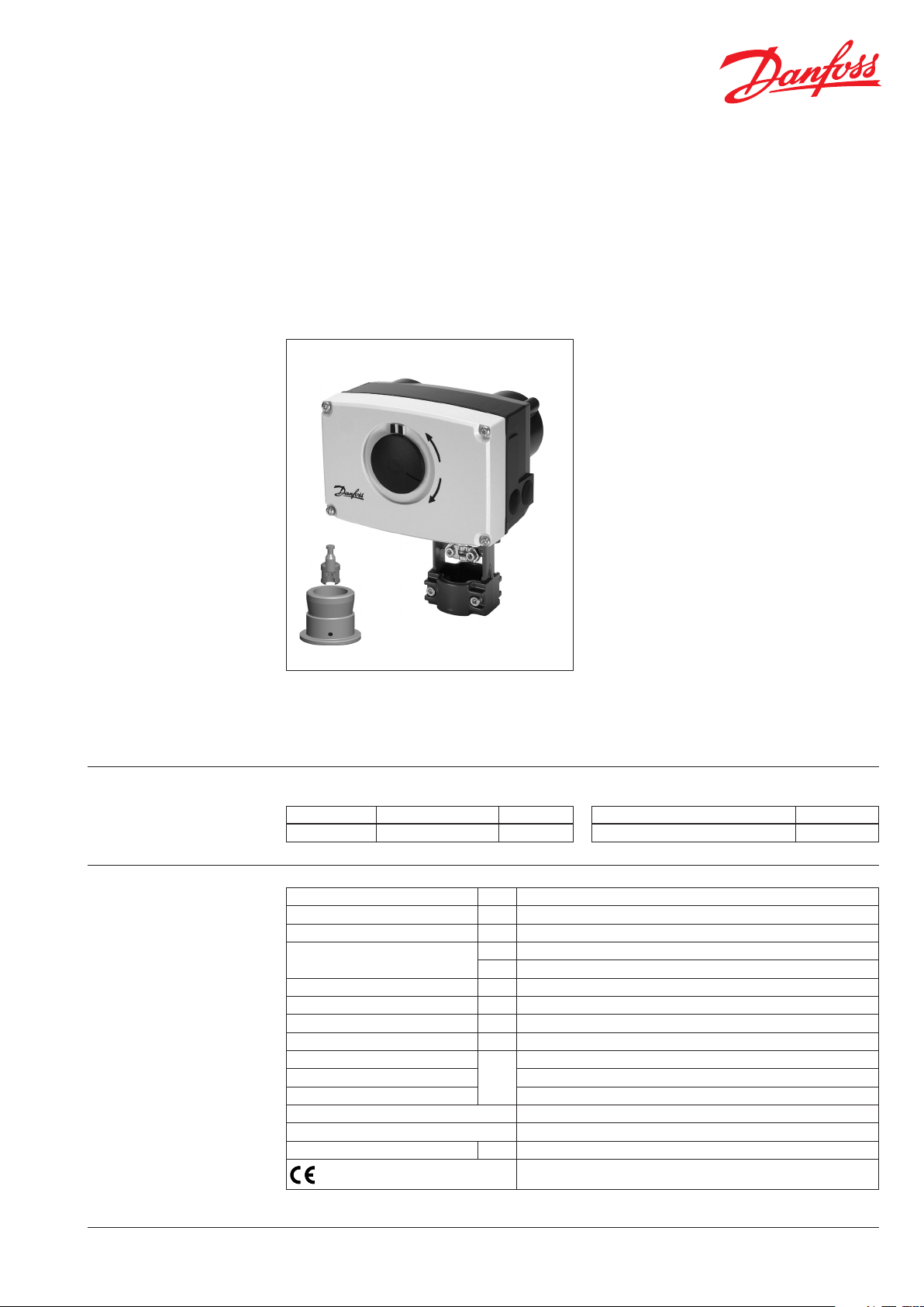
Actuator for modulating control
AME 438 SU – safety function (spring up)
Description
AME 438 SU actuator is used with two and threeway valves type VRB, VRG, VF and VL up to DN 50
diameter.
The actuator has some special features:
• it automatically adapts its stroke to the valve
end positions which reduces commissioning
time (self stroking);
• advanced design incorporates load related
‘switch-o’ to ensure that actuators and
valves are not exposed to overload;
• Safety function (spring up): In case of power
failure or power switch o spring up function
retracks actuator stem to end position;
Further manual stem positioning is not
disabled.
Main data:
• Nominal voltage:
- 24 VAC, 50 Hz/60 Hz
• Control input signal:
- 0(4)…20 mA
- 0(2) … 10 V
• Force: 450 N
• Stroke: 15 mm
• Speed: 15 s/mm
• Max. medium temperature: 150 °C
• Self stroking
• Output signal
Ordering
Technical data
DH -SMT/S I
Actuator
Typ e Supply voltage Code No.
AME 438 SU 24 VAC 082H 0121
Power supply V 24 AC, ±10%
Power consumption VA 14
Frequency Hz 50/60
Control input Y
Output signal X V 0-10 (2-10) [min. load = 5 kΩ]
Close of force N 450
Max. stroke mm 15
Speed s/mm 15
Max. medium temperature
Ambient temperature 0 … 55
Storage and transport temperature –40 … +70
Protection class III (24 V)
Degree of protection IP 54
Weight kg 2,3
- marking in accordance with
standards
VD.LE.O4.02 © Danfoss 09/2015
V 0-10 (2-10) [Ri = 200 kΩ]
mA 0-20 (4-20) [Ri = 500 Ω]
°C
Low Voltage Directive (LVD) 2006/95/EC: EN 60730-1, EN 60730-2-14
EMC Directive 2004/108/EC: EN 61000-6-2, EN 61000-6 -3
Accessories
Typ e Code No.
Stem heater (for valves DN 15-50) 065Z0315
150
1
Data sheet Actuator for modulating control AME 438 SU
Installation
Wiring
Mechanical
Use 4 mm Allan key (not part of actuator
delivery) to mount actuator on the valve.
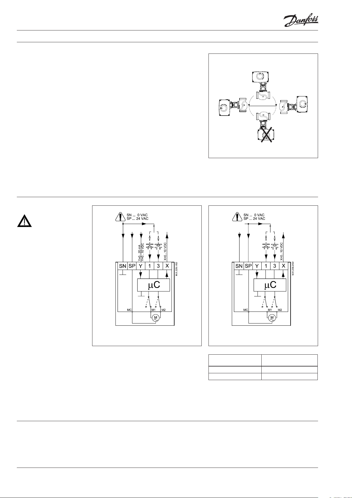
Installation of the valve with the actuator is
allowed in horizontal position or upwards.
Installation downwards is not allowed.
The actuator must not be installed in an
explosive atmosphere, at ambient temperature
lower than 0 °C or at ambient temperature higher
than 55 °C. It must not be subject to steam jets,
water jets or dripping liquid as well.
Note: the actuator may be rotated up to 360° with
respect to the valve stem by loosening the retaining
xture. Once the actuator is placed, retighten the
xture.
Electrical
Electrical connections can be accessed by
removing the actuator cover. Two cable gland
entries with thread (M20 x 1.5 and M16 x 1.5) are
prepared for cable glands.
Note: Cable and cable gland used must not
compromise the actuator’s IP rating, and must
ensure the connectors are fully strain relieved.
Please observe local rules and regulations as well.
24 V AC
Wiring for modulating control
(SW 6 in position OFF - factory set)
SP 24 VAC .........................................Power supply
SN 0 V .........................................................Common
Y 0-10 V ............................................... Input signal
(2-10 V)
0-20 mA
(4-20 mA)
X 0-10 V ........................................... Output signal
(2-10 V)
Wiring for 3-point control
(SW 6 in position ON)
Wiring length
0-50 m 0.75 mm
> 50 m 1.5 mm
Recommended crosssectional area of the wiring
2
2
Disposal
2
The actuator must be dismantled and the
elements sorted into various material groups
before disposal.
VD.LE.O4.02 © Danfoss 09/2015
DH -SMT/S I

Data sheet Actuator for modulating control AME 438 SU
Commissioning
DIP switch setting
Complete the mechanical and electrical
installation, set DIP-switches, then perform the
necessary checks and tests:
• Apply power
Note that the actuator will now perform
automatic self stroking function
• Apply the appropriate control signal and
check:
- if the valve stem direction is correct for the
application and
- the actuator drives the valve over the entire
stroke length
The unit is now fully commissioned.
Automatic self stroking feature
The actuator automatically adapts its stroke to
the valve end positions:
- when power is applied for the rst time or
- afterwards by changing of DIP switch 9 setting
(from OFF to ON and back to OFF)
Testing entire valve stroke length
The actuator can be driven to the fully-open or
closed positions (depending on valve type) by
connecting SN to terminals 1 or 3.
DIP switches
• SW 1: U/I - Input signal type selector
- OFF position; voltage input is selected
- ON position; current input is selected
• SW 2: 0/2 - Input signal range selector
- OFF position; the input signal is in the range
from 2-10 V (voltage input) or from 4-20 mA
(current input)
- ON position; the input signal is in the range
from 0-10 V (voltage input) or from 0-20 mA
(current input)
• SW 3: D/I - Direct or inverse acting mode
selector
- OFF position; the actuator is in direct acting
mode (stem extracts as voltage increases)
- ON position; the actuator is in inverse acting
mode (stem retracts as voltage increases)
• SW 4: —/Seq - Input signal range in
sequential mode
- OFF position; the actuator works in
complete input range 0(2)-10 V or 0(4)-20 mA
- ON position; the actuator works in
sequential range; 0(2)-5(6) V (or 0(4)-10(12)
mA) or 5(6)-10 V (or (10(12)-20 mA))
• SW 5: 0-5V/5-10V - Normal or sequential
mode selector
- OFF position; the actuator works in
sequential range 0(2)-5(6) V or 0(4)-10(12) mA
- ON position; the actuator works in
sequential range 5(6)-10 V or 10(12)-20 mA
SW 3
• SW 6: Prop./3-pnt - Modulating or 3-point
mode selector
- OFF position; the actuator works according
to control signal
- ON position; the actuator works as 3-point
actuator
• SW 7: LOG/LIN - Equal percentage or linear
ow through valve selector
1)
- OFF position; the ow through valve is equal
percentage according to control signal
- ON position; the ow through valve is linear
according to control signal
• SW 8: 100% KVS/Reduced KVS - Flow
reduction through valve selector
1)
- OFF position; the ow through valve is not
reduced
- ON position; the ow through valve is
reduced by half of increment standard KVS
values (example: valve with KVS 16 and SW8
set to ON – maximum ow through the valve
is K
13 (middle between standard KVS 16 and
VS
KVS10)
• SW 9: Reset
Change of DIP switch setting (from OFF to ON
and back to OFF) starts self stroking mode
1)
NOTE: To be used only i n combination with valves with e qual
percentage characteristic.
DH -SMT/S I
VD.LE.O4.02 © Danfoss 09/2015
3

Data sheet Actuator for modulating control AME 438 SU
Led signalling/
Actuator operating modes
LED operating mode indicator
Red LED function indicator is located on PCB unit
under the cover. It indicates dierent operating
modes.
LED Indication type Operating mode
Flashing three times per second Error mode
Red
≈
Dark No indication No power supply
• Self stroking mode
Self stroking mode starts automatically when
Flashing once per second Self stroking mode
Constantly lit Normal mode
• Normal mode
The actuator is operating automatically.
the actuator is connected to power supply
for the rst time. Manual start of self stroking
procedure can be done with DIP switch 9.
Self stroking procedure starts with extracting
• Error mode
Electrical error has occurred. Check wiring and
power supply or contact Danfoss support.
the actuator stem. When maximum force
is detected (at the end valve position) the
actuator retracts the stem until the maximum
force is detected again (on the other valve
end position). End positions are set and the
actuator goes to normal mode and starts
responding to the control signal.
Manual override Manual override is done by means of positioning
spindle inside the actuator:
• Disconnect power signal
• Remove the actuator cover
• Insert 5 mm Allan key (not part of actuator
delivery) into the top of the positioning spindle
• Turn the key against the spring (observe the
rotation direction)
To hold a manual override position, the key must
be wedged.
After manual override is not needed:
• Restore power signal.
5mm
4
VD.LE.O4.02 © Danfoss 09/2015
DH -SMT/S I

Data sheet Actuator for modulating control AME 438 SU
Safety function
Dimensions
The safety function will fully close the valve. The
safety function unit is factory tted to the rear of
the actuator.
Valve type Safety action will close port A-AB
VRG, VRB SU
VL (DN 15-50) SU
VF (DN 15-50) SU
or
VL 2, VF 2
=
SU
VL 3, VF 3, VRG 3, VRB 3
Actuator - valve
combinations
Adapter
065Z0311
AME 438 SU + AME 438 SU + AME 438 SU + AME 438 SU +
VRB 2, VRG 2 VRB 3, VRG 3 VF 2, VL 2 VF 3, VL 3
(DN 15-50) (DN 15-50)
DH -SMT/S I
VD.LE.O4.02 © Danfoss 09/2015
5

Data sheet Actuator for modulating control AME 438 SU
DH -SMT/S I
VD.LE.O4.02 © Danfoss 09/2015
6

Data sheet Actuator for modulating control AME 438 SU
DH -SMT/S I
VD.LE.O4.02 © Danfoss 09/2015
7
Data sheet Actuator for modulating control AME 438 SU
8
VD.LE.O4.02
Produce d by Danfoss A/S © 09/2015
 Loading...