

Page 1
Installation Guide
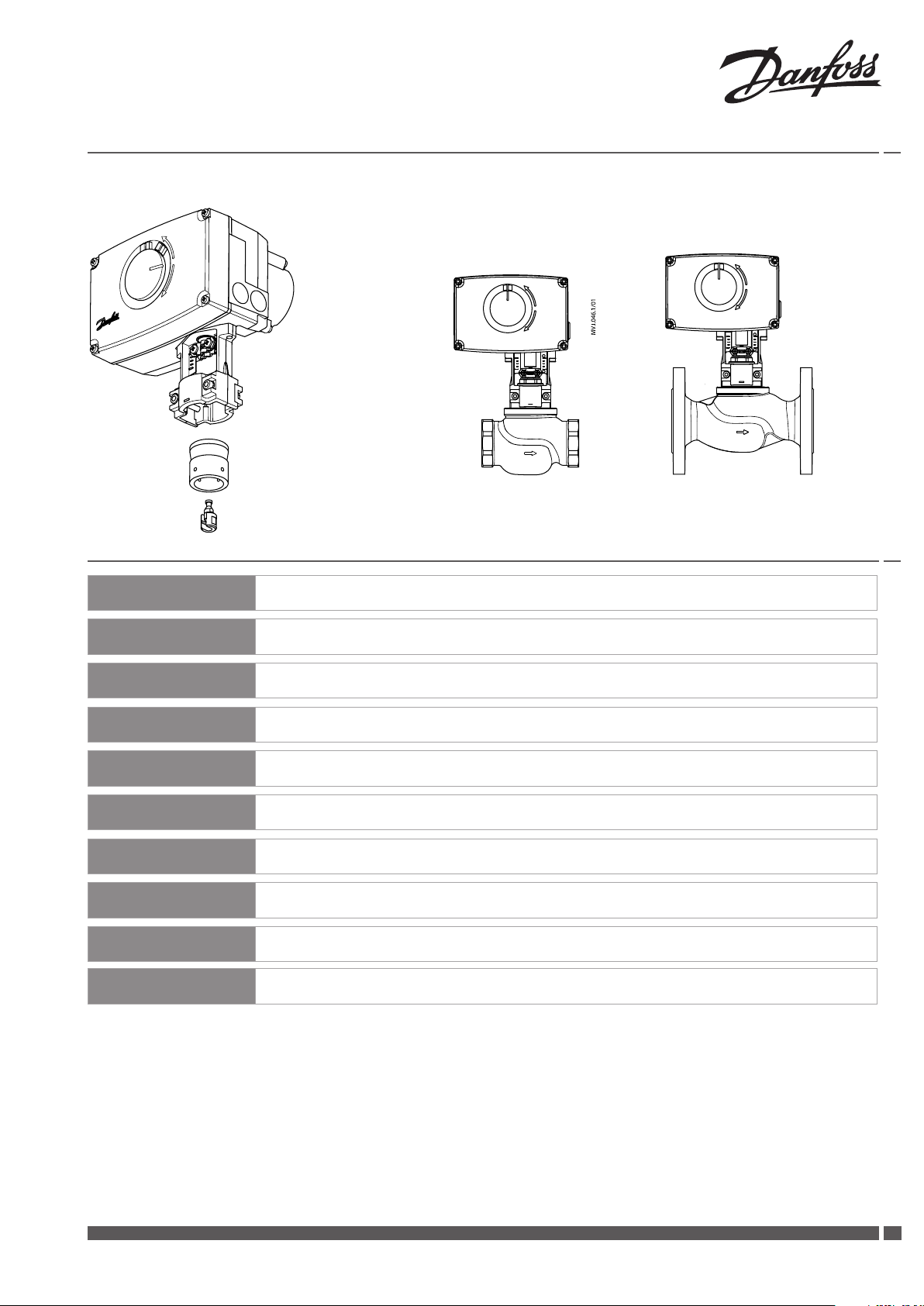
AME 438 SU
AME 438 SU + AME 438 SU +
VRB, VRG (DN 15-50) VF, VL (DN 15-50)
ENGLISH
DANSK
ESPAÑOL
SUOMI
LIETUVIŲ K.
POLSKI
РУССКИЙ
MAGYAR
中文
DEUTSCH
AME 438 SU www.danfoss.com Page 5
AME 438 SU www.danfoss.dk Side 7
AME 438 SU www.danfoss.es Página 9
AME 438 SU www.danfoss.fi Siv u 11
AME 438 SU www.sildymas.danfoss.lt Puslapis 13
AME 438 SU www.danfoss.pl Strona 15
AME 438 SU www.danfoss.ru Страница 17
AME 438 SU www.danfoss.hu Oldal 19
AME 438 SU www.danfoss.zh
AME 438 SU www.danfoss.com Seite 22
第21页
Danfoss Heating VI.LE.F2.3O DH-SMT/SI
1
Page 2
Installation Guide AME 438 SU
❶
5-7 Nm
1×6mm
②
⑤
1×
③
①
1×13mm
< 30sec.
⑤③
2mm
④
⑦
⑨
⑩
⑧
4mm
⑥
4mm
⑫
⑭
⑪
⑬
2
DH-SMT/SI VI.LE.F2.3O Danfoss Heating
Page 3
Installation Guide AME 438 SU
❷
❸
❹
①
Danfoss Heating VI.LE.F2.3O DH-SMT/SI
0-10 V
3-point
②
33
Page 4
Installation Guide AME 438 SU
❺
①
③
⑤
②
④
⑥
⑦
⑧
⑨
4
DH-SMT/SI VI.LE.F2.3O Danfoss Heating
Page 5
Installation Guide AME 438 SU
ENGLISH
Safety Note
To avoid injury and damage to persons
and devices, it is absolutely necessary
these instructions are carefully read
and observed prior to assembly and
commissioning.
Necessary assembly, start-up, and
maintenance work must be performed
only by qualified, trained and authorised
personnel.
Prior to assembly and maintenance work
on the controller, the system must be:
- depressurised
- cooled down
- emptied
- cleaned
Please comply with the instructions of the
system manufacturer or system operator.
Do not remove the cover before the power
supply is fully switched off.
Disposal instruction
This product should be
dismantled and its
components sorted, if
possible, in various groups
before recycling or disposal.
Always follow the local disposal
regulations.
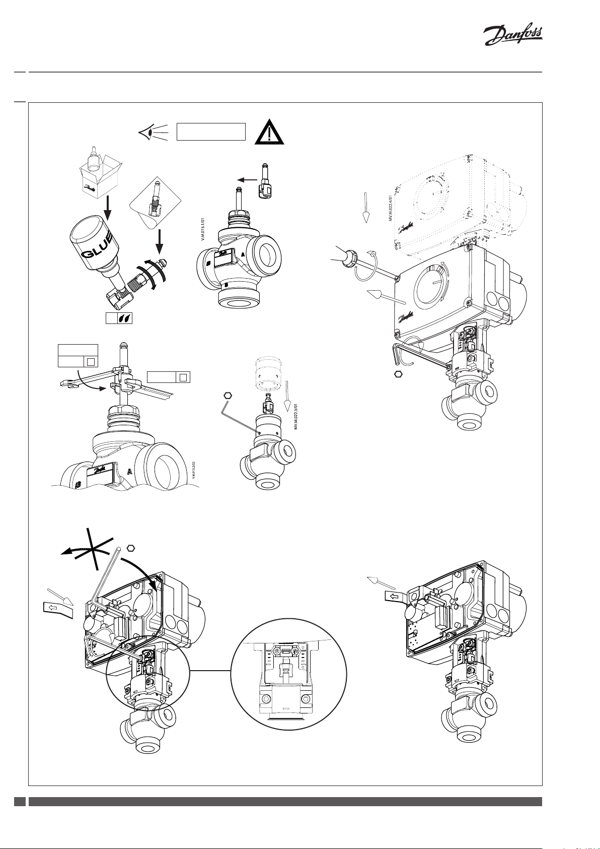
Mounting actuator
Fix the AME 438 SU on the valve. ❶
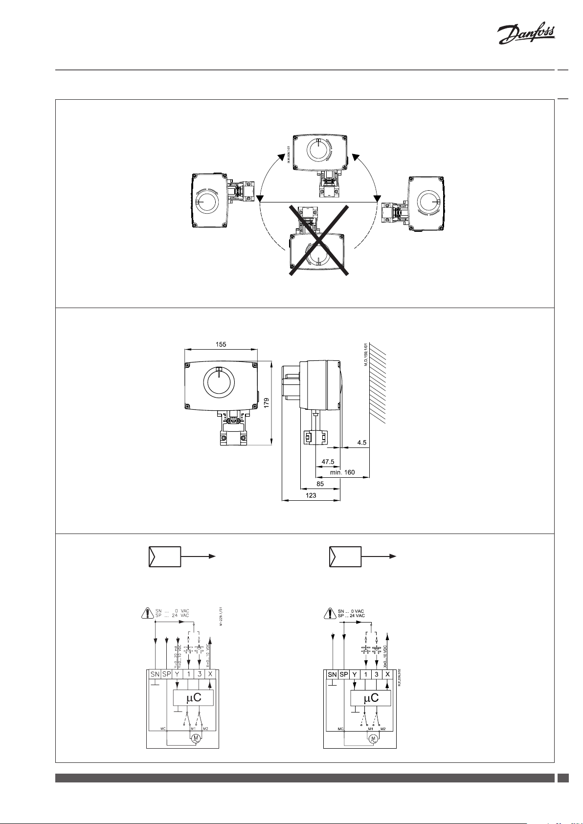
Admissible Installation Positions. ❷
Dimensions ❸
Wiring ❹①
Do not touch anything on the PCB!
Switch off the power line before wiring the
actuator! Lethal voltage!
Wire the actuator according to the wiring
diagram.
Control signal
Control signal from the controller must be
connected to terminals Y (input signal) and
SN (common) on the AME printed board.
Output signal
Output signal from the terminal X can be
used for indication of the current position.
Range depends on the DIP switch settings.
Supply voltage
Supply voltage
(24 V~ -15 to +10%, 50 Hz) must be
connected to the terminals SN and SP.
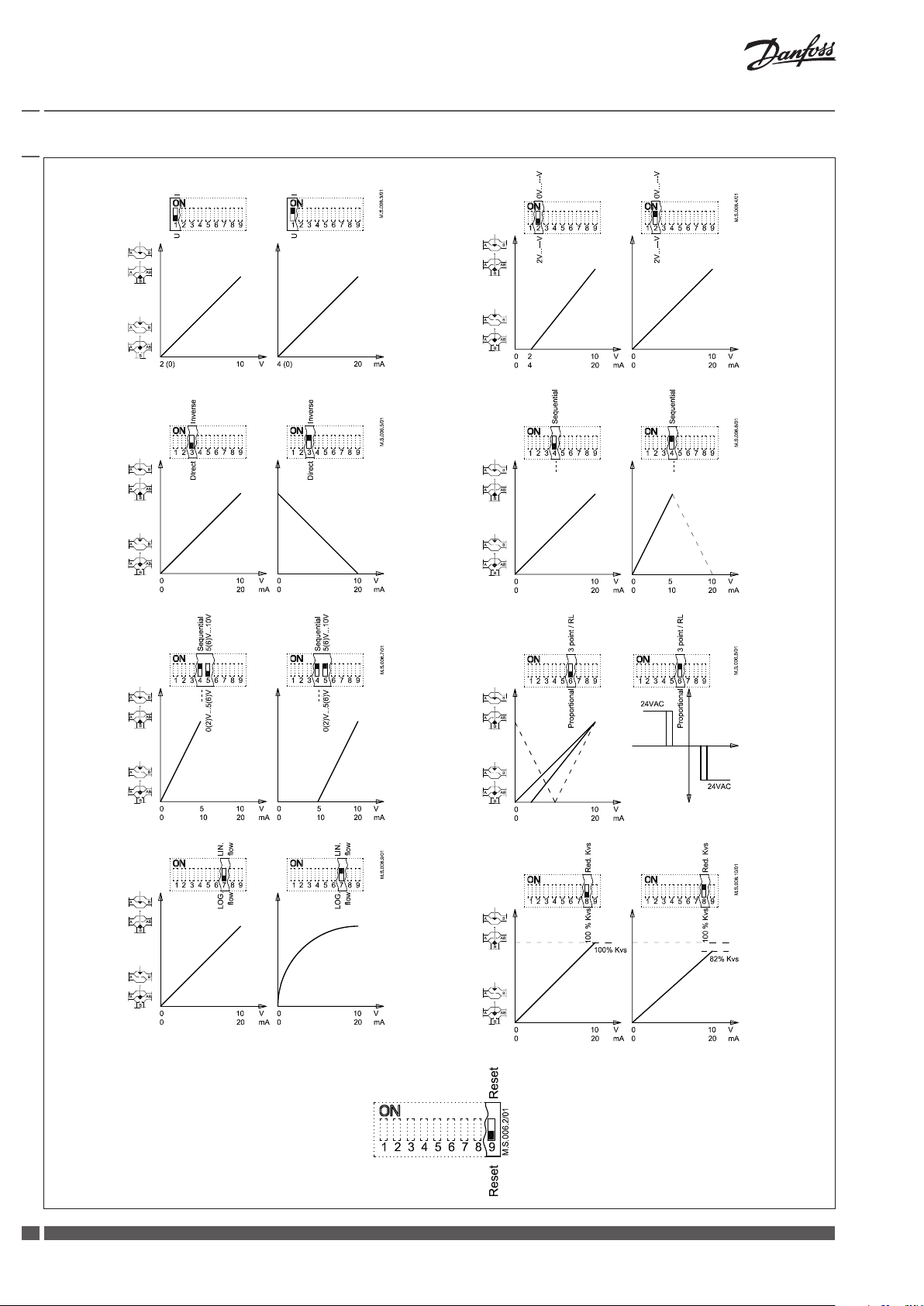
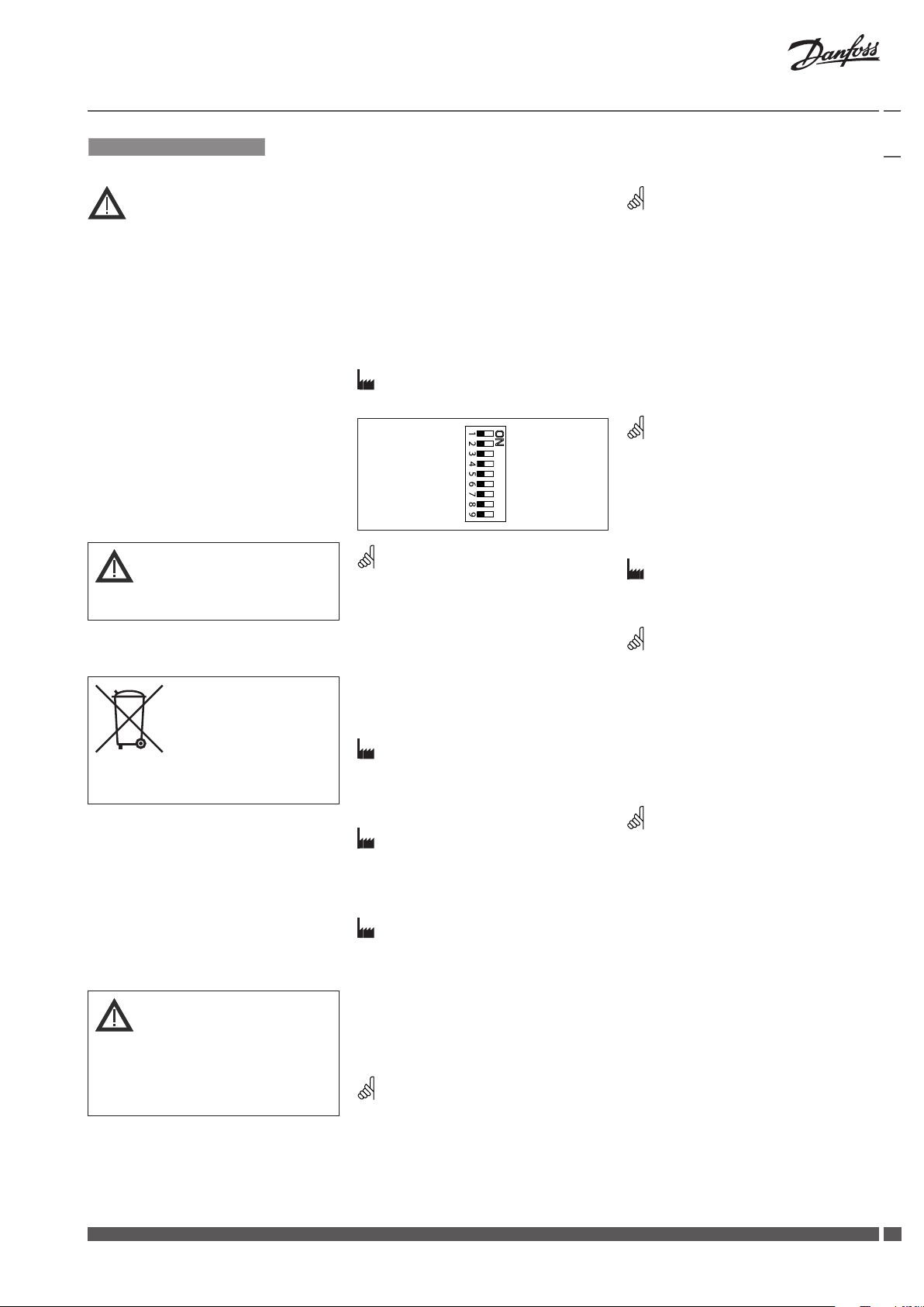
DIP switch settings ❺
Factory settings:
ALL switches are on OFF position!
Note:
All combinations of DIP switches are
allowed. All functions that are selected are
added consecutively. There is only one logic
override of functionalities i.e. the switch No.6
Proportional / 3 point, which sets actuator to
ignore control signal and works as a “simple”
3-point actuator.
SW1: U/I ❺①
Factory setting:
voltage control signal (0-10 V).
SW2: 2-10 V / 0-10 V ❺②
Factory setting is:
2-10V.
SW3: Direct/Inverse ❺③
Factory setting is:
DIRECT
SW4:---/Sequential ❺④
Two actuators can be set to work parallel
with one control signal. If the SEQUENTIAL
is set than an actuator responds to split
control signal (see 0(2)-5(6)V/5(6)-10V).
Note:
This combination works in combination with
switch No.5: 0(2)-5(6)V/5(6)-10V
U I
2 V_---V 0 V_---V
Direct Inverse
--- Sequential
0(2) V_5(6) V 5(6) V_10 V
Proportional 3 point/R L
LOG. flow L IN. flow
100 % Kvs Red. Kvs
Reset Reset
SW5: 0(2)-5(6)V/5(6)-10V ❺⑤
Note:
This function is available if switch No.4:
--- / Sequential is set.
SW6: Proportional/3 point ❺⑥
Actuator can operate as “simple” 3-point
actuator, if the 3-point function is selected.
Power supply should be connected on SN
and SP ports ❹②. On port 1 or 3 24 VAC
signal is connected for rising or lowering
of actuator. Return signal X indicates the
correct position.
Note:
if 3 point function is selected actuator does
not respond to any control signal on port Y.
It only rises and lowers spindle if power is
supplied on port 1 or 3.
SW7: LOG. flow/LIN. flow ❺⑦
Factory setting is:
LOG. Flow (characteristic of valve is
unchanged)
Note:
If this function is used in combination with
non-logarithmic valves the characteristic
of motorised valve will be anti-logarithm of
valve’s characteristic (e.g. valve with linear
characteristic will be transformed to quick
open characteristic).
SW8: 100% KVS/RED. KVS ❺⑧
Note:
This function works properly only with
logarithmic (equal percentage) valves.
SW9: Reset ❺⑨
After the actuator has been connected
to power supply, the actuator will start
the self-adjustment procedure. The
indicator LED flashes until self adjustment
is finished. The duration depends on the
spindle travel and will normally last a few
minutes. The stroke length of the valve is
stored in the memory after self adjustment
has been completed. To restart self
adjustment, change the position of RESET
switch (switch No.9). If the supply voltage
is switched off or falls below 80% in more
than 0.1 s, the current valve position will be
stored in the memory and all data remain
saved in the memory also after a power
supply cut-out.
Danfoss Heating VI.LE.F2.3O DH-SMT/SI
55
Page 6

Installation Guide AME 438 SU
Function test
The indicator light shows whether the
positioner is in operation or not. Moreover,
the indicator shows the control status and
faults.
Constant light
- normal operation
No light
- no operation or no power supply
Intermittent light (1 Hz)
- self adjusting-mode
Intermittent light (3 Hz):
- power supply too low
- insufficient valve stroke (<20 s)
- end-position cannot be reached.
6
DH-SMT/SI VI.LE.F2.3O Danfoss Heating
Page 7
Installation Guide AME 438 SU
DANSK
Sikkerhedsbestemmelser
For at undgå personskader og
erstatningsskader på produkter, er det
absolut nødvendig at gennemlæse
følgende instruktion.
Montering, opstart og vedligeholdelse må
kun foretages af kvalificeret og autoriseret
personale.
Forud for monterings- og
vedligeholdelsesarbejde på regulatoren
skal systemet være:
- trykløst
- nedkølet
- tømt
- rengjort
Leverandørens retningslinier skal følges.
Fjern ikke dækslet, før strømforsyningen er
helt koblet fra.
Bortskaffelse
Dette produkt skal skilles ad,
og enkeltdelene sorteres i
forskellige materialegrupper,
før det genbruges eller
bortskaffes.
Følg altid de lokale regulativer for
bortskaffelse.
Montering af aktuator
Fastgør AME 438 SU på ventilen. ❶
Tilladelige positioner. ❷
Mål ❸
Ledningsføring ❹①
Rør ikke ved noget som helst på printkortet!
Sluk for strømmen, inden ledningerne
trækkes til aktuatoren! Livsfarlig spænding!
Træk ledningerne til aktuatoren iht.
ledningsdiagrammet.
Styresignal
Styresignalet fra regulatoren skal tilsluttes
terminal Y (indgangssignal) og SN (fælles)
på AME´s klemrække.
Udgangssignal
Udgangssignal fra terminal X kan anvendes
til indikering af aktuel position.
Området afhænger af DIP kontakternes
indstilling.
Forsyningsspænding
Forsyningsspændingen
(24 V~ -15/+10%,50 Hz) skal tilsluttes
klemme SN og SP.
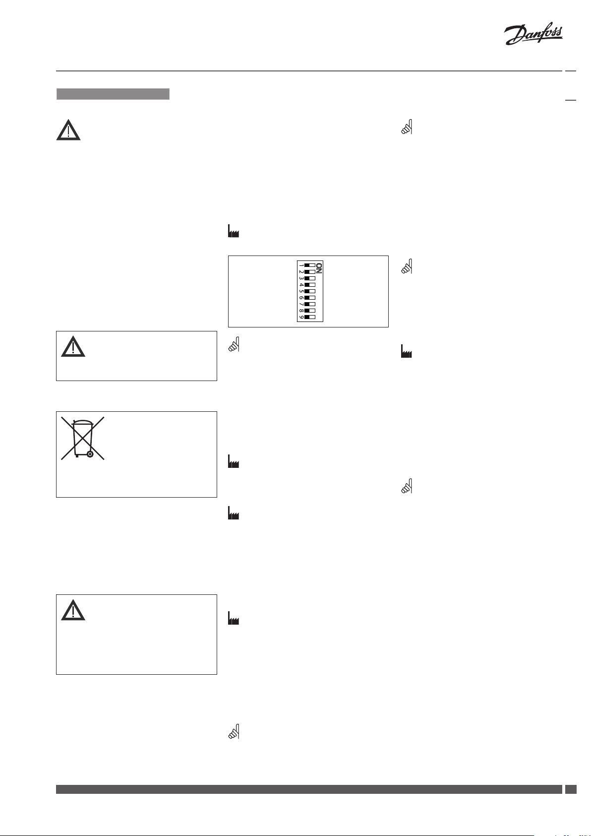
Indstilling af DIP kontakter ❺
Fabriksindstilling:
Alle kontakter er I OFF position!
Bemærk:
Alle kombinationer af kontaktindstillinger
er tilladelige. Alle funktionsvalg er tilføjet en
efter en. Der er kun en logisk overskridelse af
funktionaliteten: Kontakt Nr. 6 Proportional
/ 3-punkt styring, som sætter aktuatoren i
stand til at ignorere reguleringssignalet og
arbejde som en ”simpel” 3- punkt motor.
SW1: U/I ❺①
Fabriksindstilling:
Spændingssignal (0-10 V).
SW2: 2-10V / 0-10V ❺②
Fabriksindstilling:
2-10V.
SW3: Direkte / Indirekte ❺③
Aktuatoren kan indstilles til nedadgående
spindel ved stigende kontrolsignal
(DIREKTE)
Eller opadgående spindel ved stigende
kontrolsignal (INDIREKTE).
Fabriksindstilling:
DIREKTE
SW4: ---/ Sekvens ❺④
To aktuatorer kan arbejde parallelt med et
reguleringssignal.
I SEKVENS indstilling reagerer aktuatoren
på delt styresignal
0(2)-5(6)V/5(6)-10V.
Bemærk:
Denne kombination arbejder sammen med
kontakt Nr. 5: 0(2) - 5(6)V / 5(6) - 10V
U I
2 V_---V 0 V_---V
Direkte Sekventiel
--- Proportional
0(2) V_5(6) V 5(6) V_10 V
Omvendt 3-punkt /RL
LOG. flow L IN. flow
100 % Kvs Red. Kvs
Reset Nulstil
SW5: 0(2) - 5(6)V / 5(6) - 10V ❺⑤
Bemærk:
Denne funktion er tilgængelig hvis kontakt
Nr. 4:---/ Sekvens er indstillet.
SW6: Proportional / 3-punkt ❺⑥
Aktuatoren arbejder som en “simpel”
3-punkt aktuator, hvis 3-punkt funktionen
er valgt. Forsyningsspænding tilsluttes
klemmerne SN og SP. På klemmerne 1 og
3 tilsluttes 24VAC signal til åbne- lukke
funktion af aktuatoren. Udgangssignal X
indikerer korrekt position.
Bemærk:
Hvis 3-punkt funktionen er valgt, reagerer
aktuatoren ikke på signaler på klemme Y.
Motorspindelen bevæger sig kun opad eller
nedad ved signaler på klemme 1 eller 3.
SW7: LOG. flow / LIN. flow ❺⑦
Fabriksindstilling:
LOG.flow (ventilkarakteristikken er uændret).
Bemærk:
Anvendes denne funktion i kombination med
ikke logaritmiske ventiler, vil karakteristikken
for motorventilen blive modsat logaritmisk
i forhold til ventilkarakteristikken (d.v.s.
en ventil med lineær karakteristik vil blive
transformeret til hurtig åben karakteristik).
SW8: 100% KVS/RED. KVS ❺⑧
Bemærk:
denne funktion virker kun ved logaritmiske
ventiler.
SW9: Reset ❺⑨
Efter tilslutning af forsyningsspænding,
vil aktuatoren starte en selvjusterings
procedure. LED indikatoren blinker indtil
selvjusteringen er færdig. Varigheden
afhænger af spindelvandringen og tager
normalt nogle få minutter. Ventilens
spindelvandring lagres i hukommelsen
efter selvjusteringen er færdig. For at
starte selvjustering, skiftes positionen
af RESET kontakten (kontakt Nr. 9). Hvis
forsyningsspændingen svigter eller
falder til under 80% i mere end 0,1
sekund, vil den aktuelle ventilposition
lagres i hukommelsen og alle data bliver
bevaret i hukommelsen, også efter at
forsyningsspændingen afbrydes.
Danfoss Heating VI.LE.F2.3O DH-SMT/SI
77
Page 8

Installation Guide AME 438 SU
Funktions test
Lysdioden indikerer, om aktuatoren er
i drift, ligesom den viser driftsstatus og
eventuelle fejl.
Konstant lys
- normal drift
Intet lys
- ikke i drift, ingen strømforsyning
Interval blink (1Hz)
- selvjusteringsprocedure
Interval blink (3 Hz)
- strømforsyning for lav
- ventilslaglængde utilstrækkelig
- endestilling kan ikke nås.
8
DH-SMT/SI VI.LE.F2.3O Danfoss Heating
Page 9

Installation Guide AME 438 SU
ESPAÑOL
Nota de seguridad
A fin de evitar lesiones y daños a personas
y dispositivos, es absolutamente
imprescindible la lectura y puesta en
práctica de estas instrucciones antes de
llevar a cabo las operaciones de montaje y
puesta en servicio.
Las operaciones necesarias de montaje,
puesta en marcha y mantenimiento
deberán ser realizadas únicamente
por personal debidamente cualificado,
formado y autorizado.
Antes de llevar a cabo cualquier operación
de montaje y mantenimiento del
regulador, el sistema debe ser:
- despresurizado
- refrigerado
- vaciado
- limpiado
Por favor, respete las instrucciones del
fabricante o el operador del sistema.
No retire la cubierta antes de haber
desconectado el suministro eléctrico por
completo.
Instrucciones de eliminación
Este producto debe ser
desmantelado, clasificando
sus componentes, siempre
que sea posible, en distintos
grupos destinados a
operaciones de reciclado o
eliminación.
Respete siempre las normas de
eliminación locales.
Montaje del actuador
Instale el actuador AME 438 SU en la
válvula. ❶
Posiciones de instalación permitidas. ❷
Dimensiones ❸
Cableado ❹①
¡
No toque nada en la placa de circuito impreso!
¡Desactive la línea de suministro eléctrico
antes de conectar el actuador!
¡Tensión letal!
Conecte el actuador de acuerdo con el
esquema de cableado.
Señal de control
La señal de control procedente del
regulador deberá conectarse al terminal
Y (señal de entrada) y al terminal SN
(común) en la placa de circuito impreso del
actuador AME.
Señal de salida
La señal de salida procedente del
terminal X se puede usar para indicar la
posición actual. Su rango dependerá de la
configuración de los interruptores DIP.
Tensión de alimentación
La tensión de alimentación (24 V~ -15 a +10 %
50 Hz) debe conectarse a los terminales SN
y S P.
Configuración de los
interruptores DIP ❺
Ajuste de fábrica:
¡TODOS los interruptores deben encontrarse
en la posición OFF!
0(2) V_5(6) V 5(6) V_10 V
Restablecimiento Restablecimiento
Nota:
Todas las combinaciones de los interruptores
DIP están permitidas. Cualquier función
seleccionada se agregará consecutivamente
a las que ya se encuentren activas. El
interruptor impone únicamente una
restricción: si se activa el interruptor n.º 6
Proporcional / 3 puntos, el actuador ignorará
la señal de control y funcionará como un
actuador de 3 puntos “sencillo”.
U I
2 V_---V 0 V_---V
Directo Secuencial
--- Proporcional
Inverso 3 punto s R / L
Flujo LOG . Flujo LIN.
100 % Kvs Red. Kvs
SW1: U/I ❺①
Ajuste de fábrica:
Señal de control de voltaje
SW2: 2-10V / 0-10V ❺②
El ajuste de fábrica es:
2-10V.
SW3: Directo / Inverso ❺③
El ajuste de fábrica es:
DIRECTO
SW4:---/Secuencial ❺④
Se pueden configurar dos actuadores para
que respondan simultáneamente a una
misma señal de control. Si se establece
la posición SECUENCIAL, el actuador
responderá a una señal de control dividida
(consulte 0(2)-5(6)V/5(6)-10V).
Nota:
Esta combinación trabaja en combinación con
el interruptor No.5: 0(2)-5(6)V/5(6)-10V
,
SW5: 0(2)-5(6)V/5(6)-10V ❺⑤
Nota:
Esta función sólo está disponible si se
activa el interruptor n.º 4: ---/Secuencial.
SW6: Proporcional / 3 puntos ❺⑥
Al elegir la función de 3 puntos, el
actuador funciona como un actuador
de 3 puntos “sencillo”. La fuente de
alimentación debe conectarse a los
puertos SN y SP. La señal de 24 VAC,
destinada a desplazar el actuador en
sentido ascendente o descendente, debe
conectarse a los puertos 1 o 3. La señal de
retorno X indica la posición correcta.
Nota:
Si se selecciona la función de 3 puntos, el
actuador no responderá a la señal de control
recibida a través del puerto Y. Únicamente
desplazará el vástago en sentido ascendente
o descendente si se suministra alimentación
a través de los puertos 1 o 3.
Danfoss Heating VI.LE.F2.3O DH-SMT/SI
99
Page 10

Installation Guide AME 438 SU
SW7: Flujo LOG. / Flujo LIN. ❺⑦
El ajuste de fábrica es:
Flujo LOG. (no se modifica la característica de
la válvula)
Nota:
Si esta función se usa en conjunto con
válvulas no logarítmicas, la característica de
la válvula motorizada será el antilogaritmo
de la característica de la válvula (es decir,
una válvula con característica lineal
se transformará en una válvula con
característica de apertura rápida).
SW7: 100% Kvs / Kvs de reducción ❺⑧
Nota:
Esta función sólo funciona correctamente
con válvulas logarítmicas (de porcentaje
equivalente).
SW9: Restablecimiento ❺⑨
Después de conectar el actuador a la
fuente de alimentación, éste inicia un
proceso de ajuste automático. El indicador
LED parpadea hasta que finaliza dicho
proceso. Su duración depende de la
longitud de desplazamiento del vástago, y
suele ser de algunos minutos. El recorrido
de la válvula se almacena en la memoria
una vez llevado a cabo el proceso de ajuste
automático. Si desea realizar de nuevo el
proceso de ajuste automático, cambie la
posición del interruptor RESET (interruptor
n.º 9). Si se interrumpe la tensión de
alimentación o ésta cae por debajo del
80% durante más de un 0,1 s, la posición
actual de la válvula se guardará en la
memoria. De esta manera, todos los datos
se mantendrán guardados en la memoria
incluso en el caso de una interrupción en
el suministro eléctrico.
Prueba de funcionamiento
El indicador luminoso muestra si el motor
se encuentra en funcionamiento. Además,
este indicador muestra el estado de
control y los posibles fallos.
Encendido permanentemente
- funcionamiento normal
Apagado
- el actuador no se encuentra
en funcionamiento o no recibe
alimentación
Encendido intermitente (1 Hz)
- modo de ajuste automático
Encendido intermitente
- el nivel de la fuente de alimentación
es demasiado bajo
- el recorrido de la válvula es insuficiente
- no se alcanza la posición final.
10
DH-SMT/SI VI.LE.F2.3O Danfoss Heating
Page 11

Installation Guide AME 438 SU
SUOMI
Turvallisuushuomautus!
Nämä ohjeet on ehdottomasti luettava ja
huomioitava ennen kokoonpanoa ja
käyttöönottoa henkilö- ja
omaisuusvahinkojen välttämiseksi.
Ainoastaan ammattitaitoiset ja valtuutetut
henkilöt saavat tehdä kokoonpano-,
käynnistys- ja huoltotöitä.
Ennen säätimen kokoonpano- ja
huoltotöitä järjestelmälle on tehtävä
seuraavat toimenpiteet:
- Paineen poisto
- Jäähdytys
- Tyhjennys
- Puhdistus
Noudata järjestelmän valmistajan ohjeita.
Älä irrota kantta, ennen kuin virransyöttö
on täysin katkaistu.
Tuotteen hävittäminen jätteenä
Mikäli mahdollista tämä
tuote tulee purkaa ja lajitella
puretut osat ennen niiden
kierrättämistä tai
hävittämistä jätteenä.
Noudata aina paikallista lainsäädäntöä ja
jätehuoltomääräyksiä jätteiden
hävittämisestä.
Ohjaussignaali
Säätölaitteen ohjaussignaali on liitettävä
painetun AME-levyn liitäntöihin Y
(sisäänmenosignaali) ja SN (tavallinen
signaali).
Lähtösignaali
X-liitännän lähtösignaalia voidaan käyttää
nykyisen asennon ilmaisemiseen. Alue
määräytyy DIP-kytkinasetusten mukaan.
Käyttöjännite
Käyttöjännite (24 V~ - 15 +10 %, 50 Hz) on
yhdistettävä SN- ja SP-liitäntöihin.
DIP-kytkinasetukset ❺
Tehdasasetukset:
KAIKKI kytkimet ovat OFF-asennossa!
Verrannollinen
Nollaaminen Nollaaminen
Huom!
Kaikki DIP-kytkinasetusten yhdistelmät ovat
sallittuja. Kaikki valitut toiminnot
yhdistetään keskenään. Vain yksi logiikka
ohittaa toiminnot: kytkimen nro 6 asetus
Verrannollinen /3-piste määrittää
käyttölaitteen jättämään signaalin
huomiotta, jolloin se toimii yksinkertaisena
kolmipistekäyttölaitteena.
U I
2 V_---V 0 V_---V
Suora Käänteinen
--- Vaiheittainen
0(2) V_5(6) V 5(6) V_10 V
LOG. vir taus Lineaarinen virtaus
100 % Kvs Pien . Kvs
3-piste/RL
Kytkin4:---/Vaiheittainen ❺④
Kaksi toimimoottoria voidaan määrittää
toimimaan rinnakkain samasta
ohjaussignaalista. Jos VAIHEITTAINEN
otetaan käyttöön, toimimoottori reagoi
jaettuun ohjaussignaaliin. Lisätietoja on
kohdassa 0(2)-5(6)V/5(6)-10V.
Huom!
Tämä yhdistelmä toimii yhdessä kytkimen
nro 5 kanssa: 0(2)-5(6)V/5(6)-10V
Kytkin5: 0(2)-5(6)V/5(6)-10V ❺⑤
Huom!
Tämä toiminto on käytettävissä, jos kytkin
nro 4 ---/Vaiheittainen on määritetty.
Kytkin6: Verrannoll/3-pisteinen ❺⑥
Toimimoottori toimii yksinkertaisena
kolmipisteisenä toimimoottorina, jos
valitaan kolmipisteinen toiminta.
Virransyöttö on yhdistettävä SN- ja
SP-portteihin. 24 V a.c. yhdistetään
porteissa 1 ja 3 toimimoottorin avautumisja sulkeutumistoimintoihin. Paluusignaali X
ilmaisee oikean sijainnin.
Huom!
Jos kolmi pisteinen toiminta valitaan,
toimimoottori ei reagoi portin Y-signaaliin.
Se nostaa ja laskee karaa vain, jos portteihin
1 tai 3 syötetään virtaa.
Kytkin7: LOG. virtaus/LIN. virtaus ❺⑦
Toimimoottorin asennus
Kiinnitä AME 438 SU venttiiliin. ❶
Mahdolliset asennuspaikat. ❷
Kytkin1: U/I ❺①
Tehdasasetus:
jänniteohjaussignaali (0-10 V).
Tehdasasetus:
Logaritminen virtaus (venttiilin toiminta ei
muutu).
Huom!
Mitat ❸
Johdotus ❹①
Kytkin2: 2-10V / 0-10V ❺②
Tehdasasetus:
2-10V.
Jos tätä toimintoa käytetään yhdessä muun
kuin logaritmisen venttiilin kanssa,
moottoriventtiilin toiminta muuttuu
vastakkaisesti logaritmiseksi, eli lineaarinen
venttiili muuttuu nopeasti avautuvaksi.
Kytkin3: Suora tai käänteinen ❺③
Älä koske mihinkään piirilevyn osaan!
Katkaise virransyöttö ennen
toimimoottorin johdotusta!
Hengenvaarallinen jännite!
Johdota toimimoottori kytkentäkaavion
mukaisesti.
Danfoss Heating VI.LE.F2.3O DH-SMT/SI
Tehdasasetus:
SUORA
1111
Page 12

Installation Guide AME 438 SU
Kytkin8: 100% KVS/Pien. KVS ❺⑧
Huom!
Tämä toiminto toimii oikein vain
logaritmisissa venttiileissä.
Kytkin9: Nollaaminen ❺⑨
Kun toimimoottori on yhdistetty
virtalähteeseen, se aloittaa
itsesäätötoimet. LED-merkkivalo vilkkuu,
kunnes itsesäätötoimet on tehty. Kestoaika
määräytyy karan liikkeen mukaan, ja vie
tavallisesti muutaman minuutin. Venttiilin
karan liikkeen pituus tallennetaan muistiin,
kun itsesäätötoimet on tehty. Voit aloittaa
itsesäädön uudelleen muuttamalla
NOLLAAMINEN-kytkimen asentoa (kytkin
9). Jos virransyöttö katkeaa tai putoaa alle
80 prosenttiin yli 0,1 sekunnin ajaksi,
nykyinen venttiilin asento ja kaikki tiedot
tallennetaan muistiin. Ne säilyvät siellä
sähkökatkon ajan.
Toimintojen testaaminen
Merkkivalo ilmaisee, onko toimimoottori
käytössä vai ei. Lisäksi merkkivalo ilmaisee
ohjaustilan ja viat.
Palaa jatkuvasti
- normaali toiminta
Ei valoa
- ei toiminnassa tai ei virransyöttöä
1 Hz:n taajuudella vilkkuva valo
- itsesäätötila
Vilkkuva valo (3 Hz):
- virransyöttö ei riitä
- venttiilin iskunpituus ei riitä (<20 s)
- pääteasentoa ei voi saavuttaa.
12
DH-SMT/SI VI.LE.F2.3O Danfoss Heating
Page 13

Installation Guide AME 438 SU
LIETUVIŲ K.
Saugos informacija
Kad nesusižeistumėte ir nesugadintumėte
prietaisų, prieš montuodami ir paleisdami
būtinai atidžiai perskaitykite ir laikykitės
šių instrukcijų.
Prietaisų montavimą, paleidimą ir priežiūrą
privalo vykdyti tik kvalifikuoti, išmokyti ir
įgalioti tokius darbus atlikti specialistai.
Prieš pradedant reguliatoriaus montavimo
ir priežiūros darbus, sistema turi būti:
- be slėgio
- atvėsinta
- ištuštinta
- išvalyta
Rekomenduojame laikytis sistemos
gamintojų arba sistemos operatoriaus
instrukcijų
Nenuimkite dangtelio, kol maitinimas
nebus visiškai išjungtas
Nurodymai, kaip sunaikinti
Prieš perdirbant ar sunaikinant
šį gaminį reikia išmontuoti, o
jo dalis, jei įmanoma, surūšiuoti
atskirai
Visada laikykitės vietinių atliekų
apdorojimo taisyklių.
Pavaros montavimas
Pritvirtinkite pavarą AME 438 SU prie
vožtuvo.❶
Leistinos montavimo padėtys. ❷
Matmenys ❸
Laidai ❹①
Valdymo signalas
Reguliatoriaus valdymo signalas turi būti
prijungtas prie AME spausdintinės plokštės
gnybtų Y (įėjimo signalas) ir SN (bendrasis).
Išėjimo signalas
Terminalo X išėjimo signalas gali būti
naudojamas kaip esamos padėties
indikatorius. Diapazonas priklauso nuo
funkcijų pasirinkimo jungiklių nustatymo.
Maitinimo įtampa
Maitinimo įtampa (24 V~ -15 iki +10 %, 50 Hz
turi būti prijungta prie gnybtų SN ir SP.
Funkcijų pasirinkimo jungiklių
nustatymas ❺
Gamintojo nustatymai:
VISI jungikliai yra išjungti (padėtis OFF).
Pradinis nustatymas
,
Pastaba:
Leistini visi funkcijų pasirinkimo jungiklių
deriniai. Visos pasirinktos funkcijos pridedamos
viena po kitos. Yra veikimo perjungimo
galimybė, pvz., proporcinis / 3 padėčių šeštas
jungiklis, nustatantis pavarą nepaisyti valdymo
signalo ir veikiantis kaip paprasta 3 padėčių
pavara.
1: U/I ❺①
Gamintojo nustatymas:
įtampos valdymo signalas (0-10 V).
2: 2 - 10V / 0 - 10V ❺②
Gamintojo nustatymas:
2-10V.
2 V_---V
Tiesioginis
0(2) V_5(6) V
Proporcinis
LOG. srautas
100 % Kvs
4:---/Nuoseklusis ❺④
Dvi pavaras galima nustatyti, kad jos pagal
vieną valdymo signalą veiktų lygiagrečiai.
Jei nustatomas nuoseklusis veikimas
(SEQUENTIAL), pavara reaguoja į padalytą
valdymo signalą 0(2) - 5(6)V / 5(6) - 10V.
Pastaba:
Šis derinys veikia su jungikliu Nr. 5:
0(2) - 5(6)V / 5(6) - 10V
5: 0(2) - 5(6)V / 5(6) - 10V ❺⑤
)
Pastaba:
ši funkcija veikia, jei nustatomas 4 jungiklis:
---/Nustatytas nuoseklusis.
6: Proporcingas / 3 padėčių ❺⑥
Pasirinkus 3 padėčių funkciją, pavara gali
veikti kaip paprasta 3 padėčių pavara. Prie
SN ir SP gnybtų turi būti prijungtas elektros
U
---
I
0 V_---V
Atvirkštinis
Nuoseklusis
5(6) V_10 V
3 padėčių R /L
LIN. srautas
Red. Kvs
Pradinis nustatymas
maitinimas. 1 arba 3 gnybte prijungtas 24
VAC signalas, nuleidžiantis ir pakeliantis
pavarą. Grįžtamasis signalas X nurodo
esamą padėtį.
Pastaba:
pasirinkus 3 pavarų funkciją, pavara
nereaguoja į kanalo Y valdymo signalus.
Pavaros stiebas pakyla arba nusileidžia, jei
maitinimas prijungta prie 1 arba 3 kanalo.
7: LOG. srautas/LIN. srautas ❺⑦
Gamintojo nustatymas:
LOG. Srautas (vožtuvo charakteristika
nepakeista)
Pastaba:
Jei ši funkcija naudojama kartu su ne
logaritminiais vožtuvais, vožtuvo su pavara
charakteristika bus vožtuvo charakteristikos
antilogaritmas (pvz., tiesinė vožtuvo
charakteristika taps greito atidarymo
charakteristika).
8: 100% Kvs/RED.Kvs ❺⑧
Nelieskite jokių dalių, esančių ant
montažines plokštės!
Prieš prijungdami prie pavaros laidus,
išjunkite maitinimą! Įtampa pavojinga
3: Tiesioginis arba atvirkštinis
veikimas ❺③
Gamintojo nustatymas:
TIESIOGINIS VEIKIMAS
Pastaba:
ši funkcija tinkamai veikia tik naudojant
logaritminio srauto vožtuvus.
gyvybei!
Prijunkite pavarą pagal elektros laidų
schemą
Danfoss Heating VI.LE.F2.3O DH-SMT/SI
1313
Page 14

Installation Guide AME 438 SU
9: Pradinis nustatymas ❺⑨
Prijungus pavarą prie elektros maitinimo,
prasideda savaiminio nustatymo procedūra.
Kol vyksta ši savaiminio nustatymo procedūra,
mirksi indikatorius, pažymėtas simboliu.
Trukmė priklauso nuo stiebo eigos,
dažniausiai ši procedūra užtrunka kelias
minutes. Pasibaigus savaiminio
procedūrai, atmintyje išsaugomas
stiebo ilgis. Norėdami iš naujo pradėti
savaiminio nustatymo procedūrą, perjunkite
pradinio nustatymo jungiklį (9 jungiklį). Jei
maitinimo įtampa nutrūksta arba daugiau
negu 0,1 s jos reikšmė būna mažesnė nei
80 %, atmintyje išsaugoma esama vožtuvo
padėtis, o nutrūkus maitinimui, atmintyje
išlieka ir visi duomenys.
nustatymo
vožtuvo
Veikimo patikrinimas
Indikatoriaus lemputė nurodo, ar
pozicionavimo įrenginys veikia. Be to,
indikatorius nurodo valdymo būseną ir triktis.
Diodas šviečia nuolat
- įprastas veikimas
Nešviečia
- neveikia arba nėra elektros maitinimo
Diodas mirksi (1 Hz)
- savaiminio nustatymo režimas.
Diodas mirksi (3 Hz):
- per žema maitinimo įtampa
- nepakankama vožtuvo eiga (<20 s)
- neįmanoma pasiekti galinės padėties.
14
DH-SMT/SI VI.LE.F2.3O Danfoss Heating
Page 15

Installation Guide AME 438 SU
POLSKI
Warunki bezpieczeństwa
W celu uniknięcia zranienia osób
i uszkodzenia urządzeń należy bezwzględnie
przed montażem i uruchomieniem siłownika
zapoznać się dokładnie z niniejszą instrukcją.
Czynności związane z montażem,
uruchomieniem i obsługą mogą być
dokonywane wyłącznie przez osoby
uprawnione i odpowiednio
wykwalifikowane.
Przed montażem i obsługą konserwacyjną
należy:
- zrzucić ciśnienie,
- ostudzić urządzenie
- opróżnić układ,
- oczyścić układ
Należy postępować zgodnie z instrukcjami
producenta lub operatora systemu.
Nie zdejmować pokrywy przed całkowitym
odłączeniem zasilania.
Instrukcja usuwania odpadów
Przed złomowaniem siłownik
należy rozłożyć na części i
jeżeli to możliwe posortować
na różne grupy materiałowe.
Zawsze stosuj się do
miejscowych przepisów w zakresie
usuwania odpadów.
Montaż
Zamontować siłownik AME 438 SU na
zaworze. ❶
Dopuszczalne pozycje montażu. ❷
Wymiary ❸
Sygnał sterujący
Sygnał sterujący ze sterownika musi być
podłączony pod zaciski Y (sygnał
wejściowy) oraz SN (masa) na płytce
drukowanej siłownika AME.
Sygnał wyjściowy
Sygnał wyjściowy z pod zacisku X może
być użyty do wskazania bieżącej pozycji.
Zakres zależy od ustawień przełącznika DIP.
Zasilanie
Zasilanie
(24V~ -15 do +10%, 50Hz) musi być
podłączone pod zaciski SN i SP.
Ustawienia przełącznika DIP ❺
Ustawienia fabryczne:
wszystkie przełączniki są w położeniu OFF!
Proporcjonalny 3-punktowy/RL
UWAGA:
Dozwolone są wszystkie kombinacje
przełączników DIP.
Wszystkie wybierane funkcje są dodawane
sukcesywnie. Istnieje tylko jedno logiczne
ominięcie tych funkcji: przełącznik nr 6
Proportional /3 point (Proporcjonalny/3punktowy), który powoduje, że siłownik
ignoruje sygnał sterujący i działa jako prosty
3-punktowy siłownik.
SW1: U/I ❺①
Ustawienie fabryczne:
sterowanie sygnałem napięciowym (0-10V).
SW2: 2 - 10 V / 0 -10 V ❺②
Ustawienie fabryczne:
2 - 10V.
U I
2 V_---V 0 V_---V
Zgodnie Odwrotnie
--- Sequential
0(2) V_5(6) V 5(6) V_10 V
LOG. flow L IN. flow
100 % Kvs Red. Kvs
Reset Reset
SW4:---/Sequential ❺④
Dwa siłowniki mogą być sterowane
równolegle jednym sygnałem sterującym.
Jeśli wybrana jest opcja SEQUENTIAL,
siłownik reaguje na dzielony sygnał
sterujący (patrz 0(2)-5(6)V/5(6)-10V).
UWAGA:
To ustawienie działa w połączeniu
z przełącznikiem nr 5: 0(2)-5(6)V/5(6)-10V
SW5: 0(2)-5(6)V/5(6)-10V ❺⑤
UWAGA:
Ta funkcja jest dostępna, gdy ustawiony jest
przełącznik nr 4: --- / Sequential.
SW6: Proporcjonalny/3-punktowy ❺⑥
Siłownik może funkcjonować jako prosty
siłownik 3- punktowy po wybraniu opcji
3-point. Zasilanie należy podlączyć pod
zaciski SN i SP. Pod zaciski 1 i 3 podłączony
jest sygnał 24 VAC, służący do podnoszenia
i opuszczania siłownika. Zwrotny sygnał X
wskazuje pozycję siłownika.
UWAGA:
Jeśli wybrano opcję 3-point, siłownik nie
reaguje na jakikolwiek sygnał sterujący na
zacisku Y. Siłownik będzie podnosił i opuszczał
trzpień, jeśli na zaciski 1 i 3 podane jest napięcie.
SW7: LOG. flow/LIN. flow ❺⑦
Ustawienie fabryczne:
LOG. Flow (niezmieniona charakterystyka
zaworu)
UWAGA:
Jeśli ta funkcja jest używana w połączeniu
z zaworami nielogarytmicznymi,
charakterystyka zaworu napędzanego
będzie antylogarytmem charakterystyki
zaworu (np. zawór liniowy przekształci się
w zawór szybkiego otwarcia).
SW8: 100% KVS/RED. KVS ❺⑧
Podłączenia elektryczne ❹①
SW3: Zgodnie/Odwrotnie ❺③
Ustawienie fabryczne:
ZGODNIE
UWAGA:
Ta funkcja działa prawidłowo wyłącznie
z zaworami logarytmicznymi
(stałoprocentowymi).
Wersja na 230 V~
Nie wolno niczego dotykać na płytce
obwodu drukowanego, gdy urządzenie
jest pod napięciem! Zagrożenie życia!
Podłączenia przewodów wykonać zgodnie
ze schematem podłączeń elektrycznych.
Danfoss Heating VI.LE.F2.3O DH-SMT/SI
1515
Page 16

Installation Guide AME 438 SU
SW9: Reset ❺⑨
Po podłączeniu siłownika do zasilania
rozpoczyna się procedura samoregulacji.
Dioda LED błyska do momentu
zakończenia tej procedury. Trwa to
zazwyczaj parę minut w zależności od
skoku zaworu. Po zakończonym procesie
samoregulacji wartość skoku zaworu jest
zachowana w pamięci. Zmiana pozycji
przełącznika RESET (przełącznik nr 9)
ponownie wyzwala proces samoregulacji.
Jeżeli napięcie zasilające zostanie odcięte
lub przez okres ponad 0,1 sekundy spadnie
poniżej 80%, to aktualna pozycja zaworu
jest zachowana w pamięci; wszystkie dane
są zachowywwane również w przypadku
przerw w zasilaniu.
Test działania
Dioda świetlna wskazuje, czy silnik jest
aktywny czy też nie. Dioda LED wskazuje
też status sterowania i błędy.
Stałe świecenie
- normalna praca
Brak świecenia
- brak działania lub zasilania
Miganie z częstotliwością 1 Hz
- tryb samoregulacji
Miganie z częstotliwością 3 Hz
- zbyt niskie napięcie zasilania
- niedostateczny skok zaworu (< 20 s)
- nie można osiągnąć położenia
krańcowego.
16
DH-SMT/SI VI.LE.F2.3O Danfoss Heating
Page 17

Installation Guide AME 438 SU
РУССКИЙ
Техника безопасности
Во избежание несчастных случаев и
выхода устройства из строя необходимо
изучить и соблюдать настоящее
руководство.
Монтаж, наладка и сервисное
обслуживание устройства должны
осуществляться квалифицированным
персоналом, допущенным к данным
видам деятельности.
Работы, непосредственно связанные
с технологической системой,
следует выполнять в соответствии с
инструкциями по ее эксплуатации.
Перед началом работ по монтажу и
обслуживанию регулятора необходимо
произвести следующие действия с
трубопроводной системой:
- сбросить давление
- охладить систему
- слить воду
- очистить систему
Не снимайте крышку до того, как
питание будет полностью отключено.
Не снимайте крышку до того,
как питание будет полностью
отключено.
Инструкция по утилизации
Данная продукция
подлежит демонтажу на
части, для раздельной
утилизации составных
компонентов.
Установка
Закрепить электропривод AME 438 SU
на клапане. ❶
Монтажные положения регулятора. ❷
Габаритные ❸
Схема электрических
соединений ❹
Не прикасаться к открытым
контактам!
Отключать линию питания перед
монтажом проводки электропривода!
Опасное для жизни напряжение!
Смонтируйте проводку привода
согласно электрической схеме.
Управляющий сигнал
Управляющий сигнал с регулятора
подается на клеммы Y (входной сигнал) и
SN (ноль) платы AME.
Выходной сигнал
Выходной сигнал с клеммы Х может быть
использован для индикации текущего
положения. Диапазон зависит от настроек
переключателя DIP.
Напряжение питания
Напряжение питания (24 В переменного
тока от –15 до +10%, 50 Гц) подается на
клеммы SN и SP.
Аналоговый 3 импульсный/RL
Логарифмическая Линейная характеристика
Настройки переключателя
DIP ❺
Заводские установки:
ВСЕ переключатели находятся в
положении OFF (выключено). ❺①
ПРИМЕЧАНИЕ:
Приемлемы все комбинации
переключателей DIP. Все выбранные
функции добавляются друг к другу.
Существует только одно логическое
перерегулирование функций:
переключатель № 6 – (аналоговый/
импульсный) настраивать исполнительный механизм таким образом
аналоговый, что он игнорирует
управляющий сигнал и работает как
импульсный исполнительный механизм.
SW1: U/I (напряжение/ток) ❺①
Заводская установка:
управляющий сигнал напряжения
(0 - 10 B).
U I
2 V_---V 0 V_---V
Прямо обратно
---
0(2) V_5(6) V 5(6) V_10 V
100 % Kvs Red. Kvs
Сброс Сброс
последовательно
SW2: 2 - 10B / 0 - 10B ❺②
Исполнительный механизм можно
настроить таким образом, что он
реагирует на управляющий сигнал
не менее 2 В или 0 B. В случае, если
исполнительный механизм настроен
на токовый сигнал, он реагирует на
управляющий сигнал не менее 4 мА или
0 мА.
Заводская установка:
2-10 B.
SW3: Прямо/обратно ❺③
Заводская установка:
ПРЯМО.
SW4: ---/последовательно ❺④
Существует возможность установить
два исполнительных механизма так, что
они работают параллельно, с одним
управляющим сигналом. Если настроена
функция ПОСЛЕДОВАТЕЛЬНО, то
исполнительный механизм реагирует на
управляющий сигнал «сплит»
(см. 0(2) - 5(6) В / 5(6) - 10 В).
ПРИМЕЧАНИЕ:
Данная схема работает в комбинации с
переключателем № 5: 0(2) - 5(6) В / 5(6) - 10 В.
SW5: 0(2) - 5(6) В / 5 (6) - 10 В ❺⑤
ПРИМЕЧАНИЕ:
Данная функция имеет место лишь в
случае, если настроен переключатель №
4: ---/ последовательно.
SW6: Аналоговый / импульсный ❺⑥
Исполнительный механизм
может работать как импульсный
исполнительный механизм при условии,
что выбрана импульсная функция.
Электропитание подается на входы SN
и SP. На входы 1 и 3 подается сигнал
24 В переменного тока для подъема
и опускания штока исполнительного
механизма. Выходной сигнал Х
показывает текущее положение.
ПРИМЕЧАНИЕ:
В случае, если выбрана импульсная
функция, исполнительный механизм
не реагирует ни на какой аналоговый
управляющий сигнал на входе Y.
Исполнительный механизм поднимает и
опускает шток только в случае,
если электропитание подается на вход
1 или 3.
Danfoss Heating VI.LE.F2.3O DH-SMT/SI
1717
Page 18

Installation Guide AME 438 SU
SW7: Логарифмическая /
Линейная характеристика ❺⑦
Заводская установка:
(Логарифмическая)
характеристика регулирования
клапана не меняется.
ПРИМЕЧАНИЕ:
В случае применения данной функции
в комбинации с “нелогарифмическими”
клапанами, характеристика
моторного клапана будет являться
антилогарифмом характеристики
клапана (например, клапан с линейной
характеристикой трансформируется в
характеристику быстрого открывания).
SW8: 100% KVS/REDKVS ❺⑧
ПРИМЕЧАНИЕ:
Данная функция работает корректно
только в случае применения клапанов
с логарифмической (равнопоцентной)
характеристикой регулирования.
SW9: Reset (Сброс) ❺⑨
После подачи тока на исполнительный
механизм последний начинает
процесс автоподстройки. Об
этом свидетельствует мигание
светодиода, которое продолжается до
окончания процесса автоподстройки.
Продолжительность процесса
обычно составляет несколько минут,
в зависимости от перемещения
штока. Величина хода клапана
после окончания автоподстройки
регистрируется в запоминающем
устройстве. Процесс автоподстройки
возобновляется нажатием на кнопку
сброса «RESET» (переключатель №
9). При сбросе напряжения питания
или при его падении более чем на
80 % в течение более 0,1 с, текущее
положение клапана регистрируется
в запоминающем устройстве. Таким
образом, вся информация сохраняется в
запоминающем устройстве, в том числе
в случаях сбоя напряжения питания.
Функциональный тест
Световой диод наряду с индикацией
задействования привода производит
также индикацию рабочего состояния и
возможных ошибок.
Постоянное свечение
- обычное рабочее состояние
эксплуатации
Отсутствие свечения
- выключение, напряжение
отключено.
Прерывистое свечение (1 Гц):
- режим автоподстройки
Прерывистое свечение (3 Гц):
- электропитание слишком мало
- недостаточная величина времени
хода клапана (<20 с)
- невозможность входа в исходное
положение.
18
DH-SMT/SI VI.LE.F2.3O Danfoss Heating
Page 19

Installation Guide AME 438 SU
MAGYAR
Biztonsági megjegyzések:
A személyi sérülések és az eszközök
károsodásának elkerülése érdekében
elengedhetetlen ezeknek az utasításoknak
a figyelmes elolvasása az összeszerelés előtt,
és betartása az üzembe helyezés során.
Az összeszerelést, üzembe helyezést és
karbantartást csak szakképzett, és arra
feljogosított személy végezheti.
A szerelési és karbantartási munkálatok
előtt a rendszert:
- nyomásmentesítse
- hűtse le,
- ürítse le
- tisztítsa meg.
Kérjük, tartsa be a rendszer gyártójának és
üzemeltetőjének rendelkezéseit!
Ne távolítsa el a fedelet a tápfeszültség
teljes lekapcsolása előtt.
Hulladékelhelyezési utasítás
Vezérlőjel
A szabályozóról érkező vezérlőjelet az Y
(bemenőjel) és az SN (közös) csatlakozókra
kell csatlakoztatni az AME nyomtatott
áramköri lapon.
Kimeneti jel
Az X csatlakozóról érkező kimeneti jel
használható az aktuális pozíció kijelzésére.
A tartomány a DIP kapcsolók beállításától
függ.
Működtető fesz.
A tápfeszültséget (24 V~ -15-től +10%-ig,
50 Hz) az SN és az SP csatlakozókhoz kell
csatlakoztatni.
Mikrokapcsolók beállításai ❺
Gyári beállítások:
Mindegyik kapcsoló OFF/KI állásban van!
0(2) V_5(6) V 5(6) V_10 V
Proportional 3 pont R/L
LOG. flow LIN. vízátfolyás
100 % Kvs Red. Kvs
Fordított Visszaállítás
U I
2 V_---V 0 V_---V
Direkt Szekvenciális
--- Arányos
SW4:---/Szekvenciális ❺④
Két szelepmozgató párhuzamos
működésre állítható egy vezérlőjellel
működtetve. SZEKVENCIÁLISRA állított
helyzetben a szelepmozgató úgy reagál,
hogy felosztja a vezérlőjelet (lásd a
0(2)-5(6)V/5(6)-10V V-5(6) / 6(6) V-10V).
Megjegyzés:
This combination works in combination with
switch No.5: 0(2)-5(6)V/5(6)-10V
SW5: 0(2)-5(6)V/5(6)-10V ❺⑤
Note:
Ez a funkció akkor áll rendelkezésre, ha a
4-es számú mikrokapcsoló: --- / Szekvenciális
helyzetben van.
SW6: Arányos/3 pont ❺⑥
A szelepmozgató működhet „egyszerű”
három-pont vezérlésű állítóműként, ha a
három-pont funkció van kiválasztva. A
tápfeszültsége az SN és az SP pontokra kell
csatlakoztatni. Az 1-es vagy a 3-as ponthoz
a 24 VAC jel csatlakozik a szelepmozgató
fel, vagy le irányú mozgatásához. A
visszatérő X jel jelzi a helyes pozíciót.
A hulladékban történő
elhelyezés, vagy
újrahasznosítás előtt ezt a
terméket, ha van rá mód,
szét kell szerelni, alkatrészeit
szét kell válogatni és
csoportosítani.
Mindig tartsa be a helyi hulladékkezelési
szabályokat.
A szelepmozgató beépítése
Az AME 438 SU rögzítése a szelephez. ❶
Lehetséges beépítési helyzetek. ❷
Méretek ❸
Elektromos bekötés ❹①
Nem szabad megérinteni a nyomtatott panelt!
Kapcsolja le a táplálást, mielőtt beköti a
szelepmozgatót!
Magasfeszültség!
Kösse be a szelepmozgatót a huzalozási
rajz szerint.
Megjegyzés:
A mikrokapcsolók helyzeteinek minden
kombinációja megengedett. Minden
kiválasztott funkció egymás után hozzáadódik
a korábbiakhoz. Csak egy esetben bírálja
felül a funkcionalitásokat a logika, amikor
a 6-os számú kapcsoló a Proportional
(Arányos) / 3 ponton van, amely úgy állítja
be a szelepmozgatót, hogy az ne reagáljon a
vezérlőjelre, és „egyszerű” három-pont
vezérlésű állítóműként üzemeljen.
SW1: U/I ❺①
Gyári beállítás:
feszültség vezérlőjel
SW2: 2 - 10V / 0 - 10V ❺②
A gyári beállítás:
2-10V.
SW3: Egyenes/Fordított működés ❺③
A gyári beállítás:
EGYENES
Megjegyzés:
Ha a három-pont funkció van kiválasztva, a
szelepmozgató nem reagál semmilyen, az Y
porton megjelenő vezérlőjelre. Csak akkor
emeli fel, vagy engedi le az orsót, ha
feszültséget kap az 1-es vagy a 3-as ponton.
SW7: LOG. átfolyás/LIN. átfolyás ❺⑦
A gyári beállítás:
LOG. Vízátfolyás (a szelep jelleggörbéje
változatlan)
Megjegyzés:
Ha ezt a funkciót nem-logaritmikus
szelepekkel kombinálva alkalmazzák, akkor
a motoros szelep jelleggörbéje
antilogaritmikus szelepkarakterisztikát
mutat (például a lineáris karakterisztika
átalakul gyors nyitási karakterisztikává).
Danfoss Heating VI.LE.F2.3O DH-SMT/SI
1919
Page 20

Installation Guide AME 438 SU
SW8: 100% Kvs/RED.Kvs ❺⑧
Megjegyzés:
Ez a funkció csak logaritmikus
(egyenszázalékos) szelepek esetében
működik megfelelően.
SW9: Visszaállítás ❺⑨
Az egység tápfeszültségre kapcsolása után,
a szelepmozgató elkezdi az önbeállítást. A
LED az önbeállítás befejezéséig villog. Az
időtartam a szelepszár löketének hosszától
függ, és normál esetben a folyamat eltart
néhány percig. Az önbeállítás befejezésekor
a szeleplöket hossza eltárolásra kerül a
memóriában. Az önbeállítás újrakezdéséhez
változtassa meg a RESET mikrokapcsoló
(9-es kapcsoló) állását. Ha a tápfeszültség
lekapcsolódik, vagy 0,1 másodpercnél
tovább 80% alá esik, akkor az aktuális
szeleppozíció elmentésre kerül a memóriában.
Energiaellátás kimaradásakor az összes
adat a memóriában elmentve marad.
Működés vizsgálat
A jelzőfény mutatja, hogy a pozicionáló
működik-e vagy sem. Továbbá, a kijelző
mutatja a szabályozó státuszát és hibáit.
Állandó fényjelzés
- normál működés
No light
- nem működik, vagy nincs
energiaellátás
Villogó fény (1Hz)
- önbeállító mód
Villogó fény (3 Hz):
- tápfeszültség túl alacsony
- szeleplöket nem megfelelő
- véghelyzet nem elérhető.
20
DH-SMT/SI VI.LE.F2.3O Danfoss Heating
Page 21

Installation Guide AME 438 SU
中文
安全注意事项
为避免发生人身和设备事故,请仔细阅读
本手册。
安装、调试、维修必须由专业人员进行。
在对控制器进行安装和维护之前,必须将
系统:
- 减压
- 冷却
- 清空
- 清洁
请遵循系统制造商或系统操作人员的说
明。
电源未完全关闭前,请勿取下顶盖
弃置说明
在 回 收 或 丢 弃 前 ,应 当 将 本
产品拆卸并对元件进行归
类
请遵循当地的废弃法规。
安装驱动器
将 AMV438SU 驱动器安装到阀体上 ❶
可允许的安装位置. ❷
尺寸 ❸
接线 ❹①
切勿触碰印刷电路板上的任何元件!
连接驱动器线路之前,请关闭电源!
致命电压!
按照接线图对驱动器进行线路连接
控制信号
从控制器来的控制信号接到 AME 的 Y 端
( 输 入 信 号 )和 S N 端(公 共 端 )。
阀位反馈
阀位反馈信号从 X 端输出,SN 为公共
端。
电源电压
电源电压(24V -15% 到+10%,50Hz)连
接到端子SN和SP。
DIP拨动开关的设定 ❺
出厂设定所有位都在OFF位 置。
Proportional 3 点 R/L
SW1: U/I ❺①
驱动器既可接受电压控制信号,也可接
受电流控制信号,由拨动开关的第一选
择。
出厂设定:
电压控制信号
SW2: 2 - 10 V / 0 -10 V ❺②
驱动器可接受的控制信号可以从 2V
(或 4mA)开始,也可以从 0V (或 0mA)
开始。
出厂设定:
2- -10V
SW3: 正向/反向动作 ❺③
驱动器可以设 定为当控制信号增高时驱
动杆伸出,也可设定为当控制信号增高
是驱动杆收缩。
出厂设定:
正向
SW4: ---/顺序动作 ❺④
两个驱动器可共用一个控 制信号 并联
工作。选择顺序动作功能后控制信号将
被 分 割( 0 ( 2 ) V - 5(6 V )/ 5( 6 )V - 1 0 V )。
注意:
此项功能与拨动开关第5位配合使用。
0( 2 )V - 5( 6 V )/ 5( 6 )V - 1 0 V 。
SW5: 0(2) - 5(6) V / 5(6) - 10 V ❺⑤
注意:
此项功能当拨动开关第4位设为顺序动
作时有效。
SW6: 比例控制/三点控制 ❺⑥
驱动器可设 定为比例控制或三点控制。
三点控制时,电源连接到 SP 和 SN 端
子,24VAC 控制信号分别接到端子1和3
U I
2 V_---V 0 V_---V
正向 顺序动作
---
0(2) V_5(6) V 5(6) V_10 V
LOG. flow
100 % Kvs 红色 Kvs
反向 复位
比例
线性特性
来打开或关闭阀门。X端子为阀位反馈。
注意:
选择三点控制以后驱动器不对 Y 端子
的控制信号作出反应。
SW7: 对数流量特性/线性流量特性
❺⑦
几乎所有丹 佛斯阀门的流量特 性都是
对数特性的。如果驱动器设定为线性,
则驱动器的工作特性与阀体配合后可得
出线性的特性。
出厂设定:
对数特性
注意:
如果驱动器设定为线形而阀体特性不
是对数特性,则组合后的特性可解为快
开特性。
SW8: 100%KVS 降低/KVS ❺⑧
选择降低KVS功能后阀门的 KVS 值可
降为比它小一号阀门的 KVS 值与它本
身 KVS 值之间的中间值。如:阀门本
身 KVS值为16,比它小一号阀门的 KVS
值为10,则降低以后的 KVS 值为13。
注意:
此项功能仅对对数特性的阀门有效。
SW9: 复位 ❺⑨
驱动器第一次通电后将自动进行行程自
检,自检时 LED 指示灯闪烁直到自检
结束。自检的时间根据行程大小和速度
快慢各不相同,大致需几分钟时间。自
检结束后行程信息被记录到存储器中。
将拨动开关的第9位拨到复位位置也可
启动自检进程。电源断电或电压降低于
8 0 % 的 时 间 超 过 0 . 1 秒 ,所 有 的 当 前 数 据
被保 存到存储器中。
功能测试
LED 指示灯可提供当前状态
和故障指示:
持续亮
-正常工作
不亮
-没有任何操作或无电源电压
闪烁(1H z)
-自检中
闪烁(3 H z)
-电源电压过低
- 行 程 不 对(< 2 0 s )
-不能到达末端位置
Danfoss Heating VI.LE.F2.3O DH-SMT/SI
2121
Page 22

Installation Guide AME 438 SU
DEUTSCH
Sicherheitshinweis
Um Sach- und Personenschäden zu
vermeiden, ist es zwingend erforderlich,
diese Hinweise vor dem Zusammenbau
und der Inbetriebnahme aufmerksam zu
lesen und zu beachten.
Montage , Inbetriebnahme und
Wartungsarbeiten dürfen nur durch
qualifiziertes und autorisiertes Personal
durchgeführt werden.
Vor Montage und Wartungsarbeiten am
Regler die Anlage:
- drucklos machen
- abkühlen lassen
- entleeren
- reinigen
Die Vorgaben des Anlagenherstellers und
Anlagenbetreibers sind zu beachten.
Abdeckung erst entfernen, wenn die
Stromversorgung komplett ausgeschaltet
ist.
Entsorgungshinweis
Dieses Produkt sollte vor dem
Recycling oder der Entsorgung
zerlegt und ggf. in unterschiedliche Materialgruppen
sortiert werden.
Beachten Sie stets die örtlichen
Entsorgungsbestimmungen.
Antriebsmontage
Befestigen AMV 438 SU am Ventil ansetzen. ❶
Zulässige Einbaulagen. ❷
Spannungsregelsignal
Das Steuersignal des Reglers ist an Klemme
Y (Eingangssignal) und Klemme SN
(Sammelklemme) an der AME-Printplatte
anzuschließen.
Ausgangssignal
As Ausgangssignal von Klemme X kann
zur Anzeige der aktuellen Position benutzt
werden.Der Bereich hängt von der Brücke ab.
Spannungsversorgung
Spannungsversorgung
(24 V~ -15 to +10%, 50 Hz) ist an Klemme
SN und SP anzuschließen.
Einstellung des DIP Schalters ❺
Werkseinstellungen:
Alle Schalter befinden sich in der Position OFF!
Proportionäl 3-Punkt/RL
HINWEIS:
Alle Kombinationen von DIP-Schaltern
sind erlaubt. Gewählte Funktionen sind
hintereinandergelegt. Es gibt nur eine
logische Umsteuerung der Funktionen:
Brücke Nr. 6 proportional / 3-Punkt. Dadurch
wird der Stellantrieb so umgeschaltet, dass
das Signal ignoriert wird und arbeitet als
„üblicher“ 3-Punkt Antrieb.
SW1: U/I ❺①
Werkseinstellungen:
Spannungsregelsignal (0-10 V).
U I
2 V_---V 0 V_---V
Direkt Invertiert
--- Sequentiell
0(2) V_5(6) V 5(6) V_10 V
LOG. flow L IN. flow
100 % Kvs Red. Kvs
Reset Reset
SW4:---/Sequentiell ❺④
Zwei Antriebe können parallel mit einem
Steuersignal arbeiten. Bei der Einstellung
SEQUENTIAL Antrieb reagiert auf geteilten
Steuersignal (sehe 0(2)-5(6)V/5(6)V-10V).
HINWEIS:
Diese Kombination funktioniert mit dem
Schalter Nr. 5: 0(2)-5(6)V/5(6)-10V
SW5: 0(2)-5(6)V/5(6)-10V ❺⑤
HINWEIS:
Diese Funktion steht zur Verfügung,
wenn Schalter Nr. 4:
---/Sequentiell eingestellt ist.
SW6: Proportionäl/3-Punkt ❺⑥
Bei der gewählten 3-Punkt-Funktion kann
der Antrieb als „einfacher“ 3-Punkt Antrieb
fungieren. Die Spannungsversorgung
ist an Klemme SN und SP anzuschließen
❹②. Auf der Klemme 1 oder 3 sorgt
ein 24 V~ Steuersignal für ein Anheben
oder Absenken des Stellantriebs. Das
Ausgangssignal von Klemme X kann zur
Anzeige der aktuellen Position benutzt
werden.
HINWEIS:
Wenn die 3-Punkt-Funktion eingestellt ist,
reagiert der Stellantrieb nicht auf Signale
von der Y-Klemme. Der Antrieb bewegt die
Motorenspindel nur dann nach oben oder
nach unten, wenn ein Steuersignal auf
Steuerklemme 1 oder 3 anliegt.
SW7: LOG. flow/LIN. flow ❺⑦
Werkseinstellungen:
LOG. Flow (Ventilcharakteristik bleibt
unverändert).
Abmessungen ❸
Verdrahtung ❹①
SW2: 2-10 V / 0-10 V ❺②
Werkseinstellungen:
2-10 V.
HINWEIS:
Diese Funktion mit dem nicht logarithmischen
Ventil verwendet wird, übernimmt der Antrieb
die Anti-Logarithem der Ventilcharakteristik.
(Ventil mit linearer Kennlinie wird in die
Kennlinie umgewandelt).
SW3: Direkt/Invertiert ❺③
Keine Bauteile auf der Leiterplatte berühren!
rennen Sie das Netzkabel vor der
Verdrahtung des Stellantriebs! Tödliche
Werkseinstellungen:
DIREKT
Spannung! Schließen Sie den Stellantrieb
gemäß dem Verdrahtungsplan an.
22
DH-SMT/SI VI.LE.F2.3O Danfoss Heating
SW8: 100% KVS/RED. KVS ❺⑧
HINWEIS:
Diese Funktion arbeitet richtig nur mit
logarithmischen (gleichprozentigen) Ventilen.
Page 23

Installation Guide AME 438 SU
SW9: Reset ❺⑨
Ach Einschalten der Stromversorgung
startet der Regelantrieb den
Selbstanpassungsvorgang. Die
Leuchtdiode blinkt, bis die Anpassung
abgeschlossen ist.
Dies dauert normalerweise einige
Minuten, abhängig von der Distanz
der Spindelbewegung. Die Hublänge
des Ventils wird nach abgeschlossener
Selbstanpassung im Speicher registriert.
Der Selbstanpassungsvorgang kann
durch Drücken der RESET-Taste
wiederholt werden (Schalter No. 9). Bei
Ausfall der Versorgungsspannung - oder
beim Absinken auf einen Wert kleiner
80% - länger als 0,1 s, wird die aktuelle
Ventilposition im Speicher gespeichert.
Alle Daten sind also auch im Falle einer
Stromunterbrechung gesichert.
Funktiontest
Die LED zeigt neben dem Betriebszustand
auch Status und Fehler an.
Ein X
- normaler Betrieb
Leuchtet nicht
- kein Betrieb oder keine
Spannungsversorgung.
Blinklicht (1 Hz):
- Selbstjustierungsmodus
Blinklicht (3 Hz):
- unzureichende Stromversorgung
- Ventilhublänge unzureichend (<20 s)
- Endposition nicht erreichbar.
Danfoss Heating VI.LE.F2.3O DH-SMT/SI
2323
Page 24

Installation Guide AME 438 SU
A Danfoss nem vállal felelősséget a k atalógusokban és más nyomtatott anyagban lévő esetleges tévedésért, hibáért. Danfoss fenntar tja magának a jogot, hogy termékeit értesítés nélkül
megváltoztassa. Ez vonatkozik a m ár megrendelt termékekre is, feltéve, hogy e változtatások végrehajthatók a már elfogadott specikáció lényeges módosítása nélkül.
Az ebben az anyagban található védjegyek az érintett vállalatok tulajdonát képezik. A Danfoss és a D anfoss logo a Danfoss A/S védjegyei. Minden jog fenntartva.
73691230 / VI.LE.F2.3O
Produced by Danfoss A/S © 11/2012
 Loading...