

Page 1
Daktronics Venus® 1500 Controlled signs with Hy-Tek & FinishLynx Quick Guide 1
NOTE: This reference is intended as a guide to help configure Venus 1500
controlled signs to interface with Hy-Tek’s MEET MANAGER for track and
FinishLynx photo finish system. A software key is required to use
Venus 1500 Real Time. See ED-14511 for Hy-Tek and FinishLynx settings and
configurations.
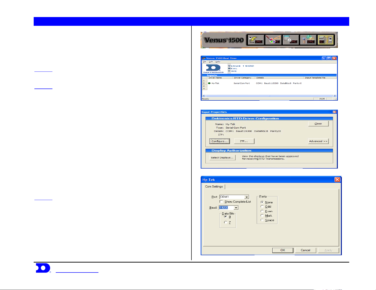
Figure 1: V1500 Shell
Venus 1500 Real Time with Hy-Tek
STEP 1: Connect a 9pin female to 9pin female null modem cable
from the Hy-Tek computer to the Venus 1500 computer.
STEP 2: Create an input for V1500 Real Time; to do this open
V1500 Real Time by clicking the V1500 Real Time button on the
V1500 shell shown in Figure 1. Right click on Input 2 on the screen
shown in Figure 2, and select New. Select Configure from the box
shown in Figure 3. In configuration select Serial Com Port, name it
Figure 2: V1500 RT
Hy-Tek, and press OK. Select the Com Port number that the 9pin
cable is plugged into on the V1500 machine, as the port number.
Baud Rate: 19200, Data Bits: 8, Parity: None. An example is shown in
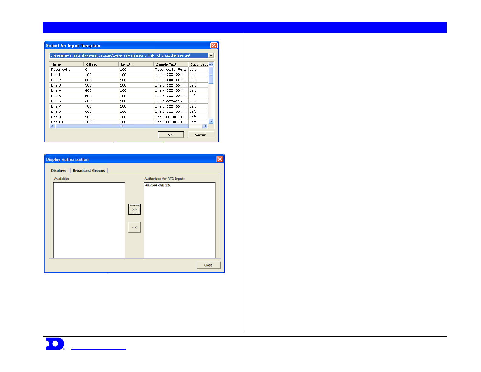
Figure 4. Press ITF on the screen in Figure 3. Click on the Down
Arrow in the upper right corner of the screen and select Browse look
in: C:\Program Files\Daktronics\Common\Input Templates\ and select
the Hy-Tek Full & Small Matrix.itf shown in Figure 5. If this file does
not show up on the list, it will need to be copied into the directory.
When complete the screen should look like Figure 5. Press Ok to
continue. Press Select Displays on the screen in Figure 3. Select the
display that the Hy-Tek data will be going to and press the Arrow to
Figure 3: Input Properties V1500 RT
move it into the column labeled Authorized for RTD Input, shown in
Figure 6, then press Close.
STEP 3: Test communication by sending data from Hy-Tek and
watch the green circle next to the input name shown in Figure 2. If it
blinks on and off, V1500 Real Time is receiving information from
Hy-Tek.
Daktronics, Inc. © 2007 P.O. Box 5128, 331 32
www.daktronics.com tel (605) 697-4036 or (877) 697-1115 fax (605) 697-4444
nd
Ave Brookings, SD 57006 ED17910-Rev 1 P1153
Figure 4: Com Port Setup
Page 2
Daktronics Venus® 1500 Controlled signs with Hy-Tek & FinishLynx Quick Guide 2
Figure 5: Input Template
Figure 6: Display Authorization
Daktronics, Inc. © 2007 P.O. Box 5128, 331 32
www.daktronics.com tel (605) 697-4036 or (877) 697-1115 fax (605) 697-4444
nd
Ave Brookings, SD 57006 ED17910-Rev 1 P1153
Page 3
Daktronics Venus® 1500 Controlled signs with Hy-Tek & FinishLynx Quick Guide 3
Venus 1500 Controlled Display with
FinishLynk via Ethernet
STEP 1: Add the V1500 computer to the network already consisting
of the FinishLynx Computer, EtherLynx camera and Galaxy display.
All components must be in the same subnet/IP Range, and Subnet
mask (255.255.255.0). The recommended addressing scheme is shown
is Figure 7.
Component IP Address
Finish Lynx Capture Computer 1 192.168.0.5
FinishLynx Capture Computer 2 192.168.0.15
Finish Lynx Edit Computer 192.168.0.25
Venus 1500 Computer 192.168.0.50
Track Scoreboards 192.168.0.51 – 192.168.0.54
Field Scoreboards 192.168.0.55 – 192.168.0.64
Hy-Tek Computers 192.168.0.90 – 192.168.0.94
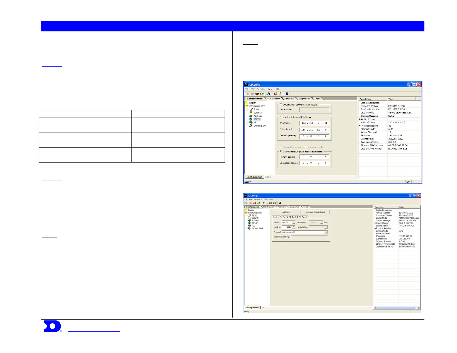
STEP 2: Using the M2Config program connect to the sign and change
the IP address within the range shown in Figure 8. This setting is
located under the communications folder and TCP/IP, which is
shown in Figure 8.
STEP 3: While connected to the sign, verify that Port 1-3 are set up as
follows:
Port 1
Type: Direct
Baud Rate: (19,200 for Galaxy Displays)
(115,200 for Galaxy Pro Displays)
Number: 1
Protocol: Venus 1500
Port 2
Type: TCP/IP
Number: 3001
Protocol: Venus 1500
Daktronics, Inc. © 2007 P.O. Box 5128, 331 32
www.daktronics.com tel (605) 697-4036 or (877) 697-1115 fax (605) 697-4444
Figure 7: Network Addressing
Port 3
Type: UDP/IP
Number: 3002
Protocol: Daktronics RTD
An example is shown in Figure 9.
Figure 8: TCP/IP settings
nd
Ave Brookings, SD 57006 ED17910-Rev 1 P1153
Figure 9: M2Config – Port Settings
Page 4

Daktronics Venus® 1500 Controlled signs with Hy-Tek & FinishLynx Quick Guide 4
Creating a FinishLynx Sequence
STEP 1: From the V1500 shell, open the V1500 Message Studio. Select
FileÆNew and pick the sign to create the desired sequence.
STEP 2: Now in the V1500 Message Studio, select
FrameÆAddÆGraphic. This will add a graphic frame to the
sequence. Graphic frames are preferred for RTD because it allows
positioning of the RTD boxes exactly where the user desires. On the
right there should be a story board with 2 frames, (frame 2 is the one
that was just added). Pick Frame 1, right click and pick Delete
Frame(s) to remove the unwanted frame.
STEP 3: Next change the Frame Duration from 2.0 seconds to 1 hour.
This is done to keep the one-tenth of a second running time smooth.
STEP 4: Now it is important to select the font to be used. It is
changeable once the field has been added by selecting the text and
picking a new font.
STEP 5: Add the RTD fields to the frame. In the V1500 Message
Studio, pick the icon on the tool bar that says RTD shown in Figure
10. Left click once on the icon then move the mouse over the frame
and pick were it will go. The RTD box is moveable after it is created.
Now the screen in Figure 11 will come up. Left click on the drop down
arrow and pick Custom ITF. To the right of the drop down arrow left
click once on the “...” (browse). From
C:\ProgramFiles\Daktronics\Common\InputTempletes\ select
FinishLynx.itf. This is the “list” of data available from FinishLynx.
STEP 6: Once the list is up use the scroll bar on the right to see the
entire list. From the list select the line with the information that is
desired and add it into the current RTD box. For example, box 1 might
be the event title, so pick Field #4. Notice that the parameters at the
bottom of Figure 12 have changed. Justify should be set to None.
Change the Length to fit the sign. Since Event Title is a word, do not
change the Item Number. It needs to start displaying from the
beginning of the field. If this were a number field like running time
then it should display MN:SC.TH and not the whole field of
Daktronics, Inc. © 2007 P.O. Box 5128, 331 32
www.daktronics.com tel (605) 697-4036 or (877) 697-1115 fax (605) 697-4444
HR:MM:SC.THT. To do this, change the Length from 12 to 8 and
change the Item Number from 1 to 4. This will filter out the first 3
characters which were HR: and the last one-thousandths of a second
digit. Another example would be Line 1 Place. Notice that it will show
numbers up to 999. To show a place up to 99 change the Length to 2
and increase the Item Number by 1. This will “filter” out the
hundreds digit.
STEP 7: Finish positioning the field and repeat steps 4 though 6 for
each field to be displayed. A sample sequence for 48 x 144 is shown in
Figure 12.
STEP 8: Remember to save and name the sequence.
NOTE: To remove the beginning of an item (i.e. the hours digits on time),
increment the “item number” and decrement the “length”.
Figure 10: RTD Field Properties
nd
Ave Brookings, SD 57006 ED17910-Rev 1 P1153
Page 5

Daktronics Venus® 1500 Controlled signs with Hy-Tek & FinishLynx Quick Guide 5
Figure 11: RTD Field Properties
Figure 12: FinishLynx RTD Sequence
Daktronics, Inc. © 2007 P.O. Box 5128, 331 32
www.daktronics.com tel (605) 697-4036 or (877) 697-1115 fax (605) 697-4444
nd
Ave Brookings, SD 57006 ED17910-Rev 1 P1153
Page 6

Daktronics Venus® 1500 Controlled signs with Hy-Tek & FinishLynx Quick Guide 6
Creating a Hy-Tek Sequence
Complete steps 1-4 from creating a FinishLynx Sequence on page 3
then follow steps 5 and 6.
STEP 5: Add the RTD fields to the frame. On the V1500 Message
Studio, pick the icon on the tool bar that says RTD shown in Figure 13.
Left click once on the icon then move the mouse over the frame and
pick were it will go. The RTD box is moveable after it is created. Now
the screen in Figure 14 will come up. Left click on the drop down
arrow and pick Input 2. This should automatically select the Hy-Tek
Full and Small Matrix.ITF that was configured in Venus 1500 Real
Time.
STEP 6: Determine how many lines of information will be displayed.
From the item list choose Line 1 for line 1 on the display, 2 for 2, etc. A
sample sequence for a 48 x 144 is shown in Figure 14.
Figure 13: RTD Field Properties
Daktronics, Inc. © 2007 P.O. Box 5128, 331 32
www.daktronics.com tel (605) 697-4036 or (877) 697-1115 fax (605) 697-4444
nd
Ave Brookings, SD 57006 ED17910-Rev 1 P1153
Figure 14: Hy-Tek RTD Sequence
Page 7

Daktronics Venus® 1500 Controlled signs with Hy-Tek & FinishLynx Quick Guide 7
Track Setup Guide – Alternate
Connection Methods
STEP 1: Hy-tek or Finishlynx can also be set up by sending RTD
directly to the M2/M3 controller in the display. For this setup connect
a 9 pin male to 9 pin female cable from the Com Port on the
Hy-Tek/Finishlynx computer to the 9 pin jack, J1, on a Daktronics
signal converter. (If no Com Ports are available, try to use USB to
Serial converters). The output on TB1 pins 1 and 2 will run to pins 2
and 6 of TB1 (CL +/-) on the M2/M3. Verify that the jumpers in the
signal converter are set 12 to N, 13 to P.
STEP 2: Using the M2Config program connect to the sign and create a
port with the following settings:
Type: Direct
Number: 2
Protocol: Daktronics RTD
Baud Rate: 19200
An example is shown in Figure 15
Figure 15: M2Config – Port Settings
Daktronics, Inc. © 2007 P.O. Box 5128, 331 32
www.daktronics.com tel (605) 697-4036 or (877) 697-1115 fax (605) 697-4444
nd
Ave Brookings, SD 57006 ED17910-Rev 1 P1153
 Loading...