

Page 1

Venus 1500 Software
Version 3
Operations Manual
ED-13530 Rev 12 – 18 April 2008
Website: www.daktronics.com
Tel: 866-343-3122 Fax: 605-697-4444
331 32nd Ave PO Box 5128, Brookings SD 57006
Page 2

ED-13530
Project-1147
Rev 12 – 18 April 2008
DAKTRONICS, INC.
Copyright 2004-2008
All rights reserved. While every precaution has been taken in the preparation of this manual,
the publisher assumes no responsibility for errors or omissions. No part of this book covered
by the copyrights here on may be reproduced or copied in any form or by any means –
graphic, electronic, or mechanical, including photocopying, taping, or information storage and
retrieval systems – without written permission of the publisher.
Venus® is a trademark of Daktronics, Inc.
Vista™, Windows 95®, Windows 98®, Windows NT® are trademarks of the Microsoft Corp.
Pentium® is a trademark of Intel, Inc.
InstallShield® is a trademarks of the InstallShield Corp.
Page 3

Reproduction Reference
ED-13530 – P1147
Venus 1500 Version 3 Operation Manual
1) This page is for reproduction reference only and will not be included in the
manual.
2) This manual is to be copied on FRONT AND BACK PAGES -8 ½ x 11 paper.
Note: The first page, Cover Page, uses the front of the page (blank on back).
Section heading pages always start on a new page; they never start on the back
of another page.
3) Materials included: Insert a copy of A-92267 in Appendix A. Insert a copy of SL4078 at the end of Appendix B.
4) Use a blue cover and back. Insert labeled, tabbed dividers before each
section.
5) Punch all pages along the left edge and bind with a spiral binder.
6) Please direct questions and suggestions to Engineering Support.
Page 4

Page 5
Introduction
1.1 System Requirements ...................................................................................................... 1
1.2 Help.................................................................................................................................... 1
1.3 Contacting Daktronics ..................................................................................................... 2
2.1 Software Installation ........................................................................................................ 3
2.2 Basic Steps to Using the Venus 1500 Control System Software ................................. 3
2.3 Navigating the Venus 1500 Software ............................................................................ 4
3.1 Display Creation Wizard ................................................................................................ 5
3.2 Network Configuration ................................................................................................... 6
Adding a Network .................................................................................................... 6
3.3 Display Configuration ..................................................................................................... 7
Editing and Deleting Displays ................................................................................ 7
Creating a Group of Displays .................................................................................. 7
3.4 Display Type Configuration ........................................................................................... 7
Adding a Multi-Galaxy Display Type .................................................................... 7
Removing a Display Type ........................................................................................ 7
3.5 Security Options ............................................................................................................... 8
3.6 Communication Defaults (Networks Default Settings) .............................................. 8
3.7 Enabling the Text Filter (Profanity Protection) ............................................................ 8
3.8 Direct Network Testing ................................................................................................... 9
3.9 Ping Testing for TCP/IP Display Connections ............................................................ 9
3.10 Zoning Configuration ...................................................................................................... 9
3.11 Remote Database .............................................................................................................. 9
3.12 Tutorials .......................................................................................................................... 10
Tutorial #1: How To Configure a Display/Network with Display Wizard .. 11
Tutorial #2: How to Configure a Network Manually ....................................... 18
Tutorial #3: How to Configure a Display Manually ......................................... 21
Tutorial #4: How to Configure a Display Type Manually ............................... 23
Tutorial #5: How to Add, Edit, and Delete a Network ...................................... 24
Tutorial #6: How to Edit a Display’s Configuration .......................................... 25
Tutorial #7: How to Delete a Display or Display Type from a Network ....... 26
Tutorial #8: How to Create a Group of Displays ............................................... 27
Tutorial #9: How to Add a Multi-Galaxy Display Type ................................... 28
Tutorial #10: How to Set Security Options ......................................................... 29
Tutorial #11: How to Modify Communication Defaults (Networks Default
Settings) .................................................................................................................... 30
Tutorial #12: How to Custom Configure — Text Filter .................................... 31
Table of Contents i
Page 6
Tutorial #13: How to Custom Configure — Zoning Configuration ................33
Tutorial #14: How to Custom Configure — Database ......................................35
Tutorial #15: How to Test a Network ..................................................................36
4.1 Toolbars ...........................................................................................................................38
Standard Toolbar.....................................................................................................38
Font Information Toolbars .....................................................................................39
Frame Toolbar .........................................................................................................40
Previewing Toolbar .................................................................................................40
Graphic Toolbar ......................................................................................................41
4.2 Color for the Version 3 Controller ...............................................................................42
Color Palette.............................................................................................................42
4.3 Frames ..............................................................................................................................46
4.4 Frame Properties ............................................................................................................48
Specifying Effects for Version 3 Displays ............................................................49
4.5 Message Properties ........................................................................................................49
Details .......................................................................................................................49
Triggers .....................................................................................................................50
4.6 Tutorials ...........................................................................................................................51
Tutorial #1: How to Create a Basic Text Message ..............................................52
Tutorial #2: How to Open an Existing Message .................................................57
Tutorial #3: How to Select Font .............................................................................58
Tutorial #4: How to Add Text and Use the Character Map ..............................59
Tutorial #5: How to Align Text (Line Justification) ............................................60
Tutorial #6: How to Use the Spell Checker .........................................................61
Tutorial #7: How to Work with Frames ...............................................................62
Tutorial #8: How to Import an Existing Message ...............................................63
Tutorial #9: How to Import Animation ................................................................64
Tutorial #10: How to Import and Scroll an Image ..............................................68
Tutorial #11: How to Resize Graphics Before Importing ..................................69
Tutorial #12: How to Import Video (AVI Files) ..................................................71
Tutorial #13: How to Scroll Text in a Graphic Frame ........................................73
Tutorial #14: How to Create Text in a Graphic Frame .......................................74
Tutorial #15: How to Add Text over Animated Background ...........................76
Tutorial #16: How to Add Real-time Data to a Message ...................................79
Tutorial #17: How to Use the Masking Tool .......................................................81
Tutorial #18: How to Draw in a Graphic Frame .................................................82
Tutorial #19: How to Create Basic Animation ....................................................85
Tutorial #20: How to Order Objects .....................................................................89
Tutorial #21: How to Use the Frame Properties Window .................................92
Tutorial #22: How to Change Frame Duration and Clear Frames ...................95
Tutorial #23: How to Set the Frame Range to Change Properties ....................96
Tutorial #24: How to Create a Real-time Data Frame to Show a Game Score 97
Tutorial #25: How to Save, Rename, and Delete a Message .............................98
Tutorial #26: How to Create New Folders ...........................................................99
Tutorial #27: How to Change the Editor Defaults ............................................101
ii Table of Contents
Page 7
5.1 Using the Schedule Studio .......................................................................................... 105
5.2 Tutorials ........................................................................................................................ 105
Tutorial #1: How to Create a New Schedule ..................................................... 106
Tutorial #2: How to Open and Edit an Existing Schedule .............................. 108
Tutorial #3: How to Rotate a Message in a Schedule ....................................... 109
Tutorial #4: How to Schedule the Brightness of a Display .............................. 110
Tutorial #5: How to Set Start and Stop Times/Dates/Days ........................... 111
Tutorial #6: How to Describe, Name, and Save a Schedule ............................ 113
Tutorial #7: How to Schedule a Message to Run Overnight ........................... 114
Tutorial #8: How to Apply Settings to Multiple Messages ............................. 115
Tutorial #9: How to Print and Exit the Schedule Studio ................................. 116
6.1 Display List ................................................................................................................... 118
Status Results ......................................................................................................... 118
Control Area .......................................................................................................... 119
6.2 Display Diagnostic Information ................................................................................. 119
6.3 Message Control View ................................................................................................. 120
Determine the Messages Running on a Display ............................................... 120
Message Control Functions ................................................................................. 121
6.4 Schedule Control .......................................................................................................... 121
Schedule Control Functions ................................................................................. 121
6.5 Script Control View ..................................................................................................... 122
6.6 Diagnostic Control ....................................................................................................... 122
Set Time/Date ....................................................................................................... 123
Set Brightness ........................................................................................................ 123
Test Patterns .......................................................................................................... 123
Temperature Offset ............................................................................................... 123
Reset Display ......................................................................................................... 124
6.7 About the Display Manager ....................................................................................... 124
6.8 Tutorials ........................................................................................................................ 124
Tutorial #1: How to Get Display Status ............................................................. 125
Tutorial #2: How to Run a Message on the Display ......................................... 126
Tutorial #3: How to Run a Schedule on a Display ........................................... 128
Tutorial #4: How to Run Messages and Schedules Combined ....................... 129
Tutorial #5: How to View the Status of Messages or Schedules on a Display130
Tutorial #6: How to Retrieve Messages from a Display .................................. 131
Tutorial #7: How to Create and Run a Script .................................................... 132
Tutorial #8: How to Create a Script to Blank the Display ............................... 135
Tutorial #9: How to Edit a Script ........................................................................ 136
Tutorial #10: How to Configure Script Pages ................................................... 137
Tutorial #11: How to Copy and Paste Scripts ................................................... 138
Tutorial #12: How to Get Diagnostic Information ............................................ 138
Table of Contents iii
Page 8
7.1 Broadcast Groups .........................................................................................................139
7.2 Display or Broadcast Group Configuration ..............................................................140
7.3 Configuring Inputs .......................................................................................................140
Configuring ITF Files ............................................................................................140
Select Displays .......................................................................................................140
7.4 Input Defaults ...............................................................................................................140
7.5 Tutorials .........................................................................................................................141
Tutorial #1: How to Configure Settings for a Real Time Frame .....................142
Tutorial #2: How to Create a Real-time Data Frame for a Game Score .........147
Tutorial #3: How to Configure a Display ..........................................................149
Tutorial #4: How to View Advanced RTD ........................................................150
Tutorial #5: How to Edit Input Defaults ............................................................152
Tutorial #6: How to Get Data Status (Monitor) ................................................153
Tutorial #7: How to Create a Broadcast Group ................................................154
C.1 Compatible Languages ................................................................................................161
C.2 Initial Settings ...............................................................................................................162
C.3 Displaying the Font ......................................................................................................163
iv Table of Contents
Page 9

Figure 1: Tutorial Symbol ........................................................................................................................ 1
Figure 2: About Dialog ............................................................................................................................ 2
Figure 3: Venus 1500 Shell..................................................................................................................... 4
Figure 4: Right-click Menu ...................................................................................................................... 4
Figure 5: Venus 1500 Administrator – Display Configuration ................................................................. 5
Figure 6: Shared Database ..................................................................................................................... 9
Figure 7: Display Wizard ....................................................................................................................... 11
Figure 8: Auto Detect Setup ................................................................................................................. 11
Figure 9: Detected Display Description................................................................................................. 12
Figure 10: Security Option .................................................................................................................... 12
Figure 11: Display Summary................................................................................................................. 13
Figure 12: Import Animations................................................................................................................ 13
Figure 13: Display Wizard Network Configuration ................................................................................ 14
Figure 14: Network Type Configuration ................................................................................................ 14
Figure 15: COM Port Selection ............................................................................................................. 15
Figure 16: Auto Detect Setup ............................................................................................................... 15
Figure 17: Display Found ...................................................................................................................... 16
Figure 18: Select Time Zone ................................................................................................................ 16
Figure 19: Auto Detection Summary ..................................................................................................... 17
Figure 20: Network Communications .................................................................................................. 18
Figure 21: Network Configuration ........................................................................................................ 18
Figure 22: Dialup Network Configuration Box ...................................................................................... 19
Figure 23: TCP/IP Network Configuration ........................................................................................... 20
Figure 24: TCP/IP Network Configuration Box .................................................................................... 20
Figure 25: Display Configuration ........................................................................................................... 21
Figure 26: Display Type Configuration ................................................................................................. 23
Figure 27: Select a Network ................................................................................................................. 24
Figure 28: Network Configuration Dialog .............................................................................................. 24
Figure 29: Removing a Network Warning ............................................................................................ 24
Figure 30: Edit Display .......................................................................................................................... 25
Figure 31: Edit Display Configuration .................................................................................................. 25
Figure 32: Delete Display Warning ....................................................................................................... 26
Figure 33: Display Group Configuration............................................................................................... 27
Figure 34: Multi Galaxy Display Configuration ..................................................................................... 28
Figure 35: Security Options Button ....................................................................................................... 29
Figure 36: Password Entry ................................................................................................................... 29
Figure 37: Communication Defaults .................................................................................................... 30
Figure 38: Text Filter Setup ................................................................................................................. 31
Figure 39: Zoning Configuration ........................................................................................................... 33
Figure 40: Display Configuration - Restrictions ................................................................................... 34
List of Figures v
Page 10

Figure 41: Select Database Window .................................................................................................... 35
Figure 42: V15Admin Prompt ................................................................................................................ 35
Figure 43: Ping Testing ........................................................................................................................ 36
Figure 44: Venus 1500 Message Studio ............................................................................................... 37
Figure 45: Standard Toolbar ................................................................................................................. 38
Figure 46: Venus Font Text Toolbar ..................................................................................................... 39
Figure 47: True Type Font Text Toolbar ............................................................................................... 39
Figure 48: Frame Toolbar ..................................................................................................................... 40
Figure 49: Previewing Toolbar .............................................................................................................. 40
Figure 50: Brush Options ...................................................................................................................... 41
Figure 51: Fill Color Options .................................................................................................................. 42
Figure 52: RGB Values in Message Studio ........................................................................................... 42
Figure 53: Basic Color Palette ............................................................................................................... 43
Figure 54: More Colors Palette ............................................................................................................. 43
Figure 55: Define Custom Colors Palette .............................................................................................. 43
Figure 56: Basic Color Palette for Tricolor Display ................................................................................ 44
Figure 57: Custom Color Palette for Tricolor Display ............................................................................ 44
Figure 58: Basic Color Palette for Monochrome Display....................................................................... 45
Figure 59: Custom Colors Palette for Monochrome Display ................................................................. 45
Figure 60: Frames ................................................................................................................................. 46
Figure 61: Available Font List ................................................................................................................ 46
Figure 62: Frame Effects ....................................................................................................................... 48
Figure 63: Frame Properties Window ................................................................................................... 48
Figure 64: Effect Options ...................................................................................................................... 49
Figure 65: Message Properties - Details ............................................................................................... 49
Figure 66: Message Properties - Triggers ............................................................................................. 50
Figure 67: New Message Dialog ........................................................................................................... 52
Figure 68: Top and Center Aligned Text ............................................................................................... 52
Figure 69: Spell Check .......................................................................................................................... 53
Figure 70: Color Palette ........................................................................................................................ 53
Figure 71: Outline Text Example ........................................................................................................... 54
Figure 72: Shadow Text Example ......................................................................................................... 54
Figure 73: Save Message Dialog .......................................................................................................... 55
Figure 74: New Folder Dialog ................................................................................................................ 56
Figure 75: Name Length Message ........................................................................................................ 56
Figure 76: Message for Illegal Characters ............................................................................................ 56
Figure 77: Open Message Dialog .......................................................................................................... 57
Figure 78: Font Name Box .................................................................................................................... 58
Figure 79: Text Frame ........................................................................................................................... 59
Figure 80: Text Menu ............................................................................................................................ 59
Figure 81: Character Map ..................................................................................................................... 59
Figure 82: Editor Defaults ...................................................................................................................... 60
Figure 83: Text Menu ............................................................................................................................ 61
vi List of Figures
Page 11

Figure 84: Spell Check ......................................................................................................................... 61
Figure 85: Adding a New Frame ........................................................................................................... 62
Figure 86: Select Venus 1500 Message File(s) .................................................................................... 63
Figure 87: File and Import Menu ........................................................................................................... 64
Figure 88: Insert CD ............................................................................................................................. 64
Figure 89: Venus 1500 Installation Box ................................................................................................ 65
Figure 90: Select Display Type Dialog .................................................................................................. 65
Figure 91: FTP Login Configuration ...................................................................................................... 66
Figure 92: Scrolling Graphic Import Window ........................................................................................ 68
Figure 93: Scrolling Graphic Import Tools ............................................................................................ 68
Figure 94: Creating Graphic Sequence ................................................................................................ 68
Figure 95: Attributes Window................................................................................................................ 69
Figure 96: Stretch and Skew Window .................................................................................................. 69
Figure 97: Image Size Window ............................................................................................................. 70
Figure 98: Video Import ........................................................................................................................ 71
Figure 99: Video Import Options ........................................................................................................... 72
Figure 100: First Scrolling Text Dialog .................................................................................................. 73
Figure 101: Text Animation Import Tools ............................................................................................. 73
Figure 102: Second Scrolling Text Dialog ............................................................................................ 73
Figure 103: Venus Font Selection ........................................................................................................ 74
Figure 104: Frame Properties – Flash Rate ......................................................................................... 75
Figure 105: Copy Object(s) To Menu ................................................................................................... 76
Figure 106: Copy Object(s) To Window ............................................................................................... 76
Figure 107: Copy To Range of Frames ................................................................................................ 77
Figure 108: Date Format Window ......................................................................................................... 79
Figure 109: Inserted Date ..................................................................................................................... 79
Figure 110: Mask Tool .......................................................................................................................... 81
Figure 111: Sample Drawing 1 ............................................................................................................. 83
Figure 112: Sample Drawing 2 ............................................................................................................. 83
Figure 113: Sample Drawing 3 ............................................................................................................. 84
Figure 114: Basic Animation Example .................................................................................................. 85
Figure 115: Basic Animation Example 2 ............................................................................................... 86
Figure 116: Moving the Graphic from Frame to Frame ........................................................................ 87
Figure 117: Placement of Shape in Frame ........................................................................................... 87
Figure 118: Bouncing Ball Frame Sequence ........................................................................................ 88
Figure 119: Placing Objects in Message Studio ................................................................................... 89
Figure 120: Hidden Graphic .................................................................................................................. 90
Figure 121: Copying the Frame ............................................................................................................ 90
Figure 122: Center Aligning Text .......................................................................................................... 92
Figure 123: Entry Effect Example ......................................................................................................... 93
Figure 124: Example of Different Effects in Frames ............................................................................. 94
Figure 125: Frame Properties ............................................................................................................... 96
List of Figures vii
Page 12

Figure 126: RTD Field Properties.......................................................................................................... 97
Figure 127: Save Message Dialog ........................................................................................................ 98
Figure 128: Save Message Dialog ........................................................................................................ 99
Figure 129: New Folder ......................................................................................................................... 99
Figure 130: Editor Default Dialog ........................................................................................................ 101
Figure 131: Venus 1500 Schedule Studio ........................................................................................... 103
Figure 132: Version 3 Schedule Toolbar ............................................................................................. 103
Figure 133: New Schedule .................................................................................................................. 106
Figure 134: Event Menu ...................................................................................................................... 106
Figure 135: Open Schedule – Showing Schedules ............................................................................. 108
Figure 136: Rotate Frequency ............................................................................................................. 109
Figure 137: Schedule Brightness ........................................................................................................ 110
Figure 138: Changing Start and Stop Times ....................................................................................... 111
Figure 139: First Date/Last Date ......................................................................................................... 111
Figure 140: Week Days Filter .............................................................................................................. 115
Figure 141: Setting Event Times ......................................................................................................... 115
Figure 142: Venus 1500 Display Manager .......................................................................................... 117
Figure 143: Advanced Status .............................................................................................................. 118
Figure 144: Available Memory Gauge ................................................................................................. 118
Figure 145: Display List Right-Click Menu .......................................................................................... 119
Figure 146: Display Properties Dialog ................................................................................................. 119
Figure 147: Configuration Manager ..................................................................................................... 119
Figure 148: Message Control Buttons ................................................................................................. 121
Figure 149: Display Manager - Message Scheduler ........................................................................... 121
Figure 150: Schedule Control Buttons ................................................................................................ 121
Figure 151: Script Control View ........................................................................................................... 122
Figure 152: Venus 1500 Display Manager - Diagnostic Control ......................................................... 122
Figure 153: Test Patterns Options ...................................................................................................... 123
Figure 154: Display Manager Drop-Down Menu ................................................................................. 124
Figure 155: Advanced Status .............................................................................................................. 125
Figure 156: Warning Message ............................................................................................................ 128
Figure 157: Warning Message ............................................................................................................ 129
Figure 158: Messages Screen ............................................................................................................ 130
Figure 159: Script Wizard Dialog ........................................................................................................ 132
Figure 160: Script Wizard Step 2 ........................................................................................................ 132
Figure 161: Script File Browse Window .............................................................................................. 133
Figure 162: Script Wizard Summary Window ..................................................................................... 133
Figure 163: Blank Display Script ......................................................................................................... 135
Figure 164: Editing a Script ................................................................................................................. 136
Figure 165: Edit a Blank Display Script ............................................................................................... 136
Figure 166: Script Configuration Dialog .............................................................................................. 137
Figure 167: Venus 1500 Real-time Main Screen ................................................................................ 139
Figure 168: Real Time System Tray Icon ............................................................................................ 139
viii List of Figures
Page 13

Figure 169: Real-time Window ........................................................................................................... 142
Figure 170: Input Properties Window ................................................................................................. 142
Figure 171: Configure Input Window .................................................................................................. 143
Figure 172: Serial Com Port Settings Window ................................................................................... 143
Figure 173: Select an Input Template ................................................................................................. 144
Figure 174: Select an Input Template ................................................................................................. 144
Figure 175: Display Authorization ....................................................................................................... 145
Figure 176: Highlight Corresponding Input ......................................................................................... 145
Figure 177: RTD Field Properties ....................................................................................................... 147
Figure 178: Adding Fields to the Frame ............................................................................................. 148
Figure 179: Display Configuration Window ......................................................................................... 149
Figure 180: Setting the Display’s Enhanced RTD Display # ............................................................... 149
Figure 181: Input Properties Window ................................................................................................. 150
Figure 182: ERTD Select Frame Setup .............................................................................................. 151
Figure 183: Edit Menu......................................................................................................................... 152
Figure 184: Setup RTD Input Buffer Sizes ......................................................................................... 152
Figure 185: Monitor Window ............................................................................................................... 153
Figure 186: Edit Broadcast Group Window ........................................................................................ 154
Figure 187: Edit Menu......................................................................................................................... 155
Figure 188: Select Broadcast Group to Edit ....................................................................................... 155
Figure 189: Edit Broadcast Group Window ........................................................................................ 155
List of Figures ix
Page 14

Page 15
Figure 1:
Tutorial
Symbol
Introduction
The purpose of this manual is to assist in the installation and operation of the Venus 1500 Display
Network. This section will give the specifications for Venus 1500 software and provide Daktronics’
contact information.
Each section of this manual contains the following parts:
A detailed description on a variety of topics related to the controller
Practice exercises
Tutorials that teach systematic processes accompanied by screen shots and example
sequences.
Note 1: The screen shots in this manual may vary from those on the user’s computer.
Note 2: At the end of the sections are tutorials, designated by this symbol in the corner of
the page (Figure 1).
The Venus 1500 operating software has the following minimum system requirements:
Personal computer running Windows 98, Me , 2000, XP or Vista with the most
current updates installed, 32-bit versions only.
Note: Venus 1500 Real-time requires Windows 2000, XP, or Vista.
Pentium
®
II processor, 400 MHz or higher
128MB RAM or higher
50MB free hard disk space
Microsoft
®
Internet Explorer 6.0 or higher
CD-ROM Drive
Mouse or other compatible pointing device
Supported communication device (serial port, modem, or Ethernet Network)
One or more Venus 1500-compatible displays installed.
Help is available from the Help pull-down menu in Venus 1500 Message Studio, Schedule
Studio, and Administrator. Two options will appear: Contents and About.
Note: When in Display Manager, click on the yellow question mark in the upper-left side of
the screen to access the Contents help screen.
Contents
Press <ALT+C> or click Contents to access the Contents help screen. This screen can also be
accessed directly from the main screen by pressing <F1>. The contents screen will direct the
user to the electronic manual.
Introduction 1
Page 16
2
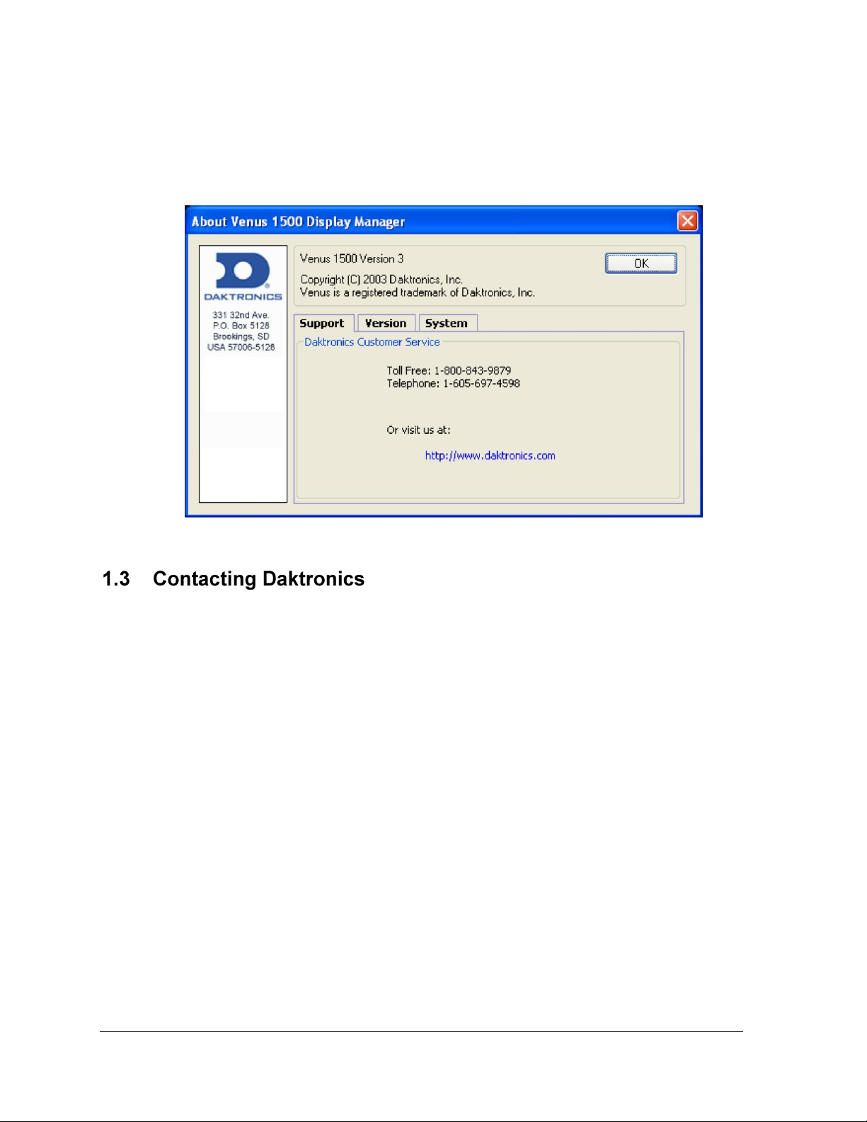
Figure 2: About Dialog
About
Each area of the software (Message Studio, Schedule Studio, etc.) contains a Venus 1500 About
dialog box that can be accessed from the Help pull-down menu. The Venus 1500 About box
contains information about the software, including software version and Daktronics’ contact
information. Click OK or press Enter to exit the Venus 1500 About box. Refer to Figure 2.
If any problems or questions arise that are not discussed in this manual, contact Daktronics
using any of the following methods:
Mail: Daktronics Customer Service
PO Box 5128
331 32nd Avenue
Brookings, SD 57006
Phone: Customer Service: 800-843-9879 (toll free) or 605-697-4598
Website: http://www.daktronics.com
Introduction
Page 17
This section will give instructions on the installation of the Venus® 1500 software and a general
description of the command buttons and applications.
The Venus 1500 software must be installed to a hard disk before use. To install the software
onto a computer, follow these steps:
1. Place the Venus 1500 installation compact disk (CD) into the appropriate CD-ROM
(presume drive D:).
2. The installation should begin automatically within a few seconds. If it does not, click
on the Start button and select Run from the menu. Type ―D:\SETUP‖ and press
Enter.
3. Follow the instructions on the screen. SETUP will copy the necessary files to run the
Venus 1500 software to the hard disk and create Venus 1500 in the Start menu.
Note: The Venus 1500 software installs to the C:\Program Files\Daktronics\Venus
1500 directory by default; this is the recommended location.
4. The Venus 1500 control software is now installed and ready to be configured for use
with the Venus 1500 Display Network.
This manual is laid out in a basic chronological order to create and display a message. The
basic steps are:
1. Install the Venus 1500 Control System software if it is not already installed on the
computer (Section 2.1).
2. Configure the display type(s) and communication method (Sections 3).
3. Create the message(s) (Section 4).
4. Create the schedule(s), when desired (Section 5).
5. Send the message/schedule to the display (Section 6).
6. Run the message/schedule (Section 6).
Getting Started 3
Page 18
4
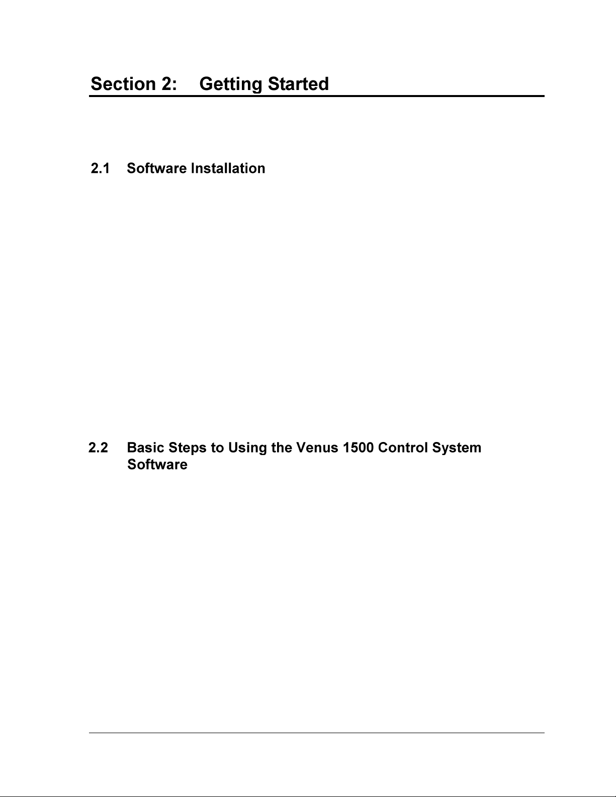
Figure 3: Venus 1500 Shell
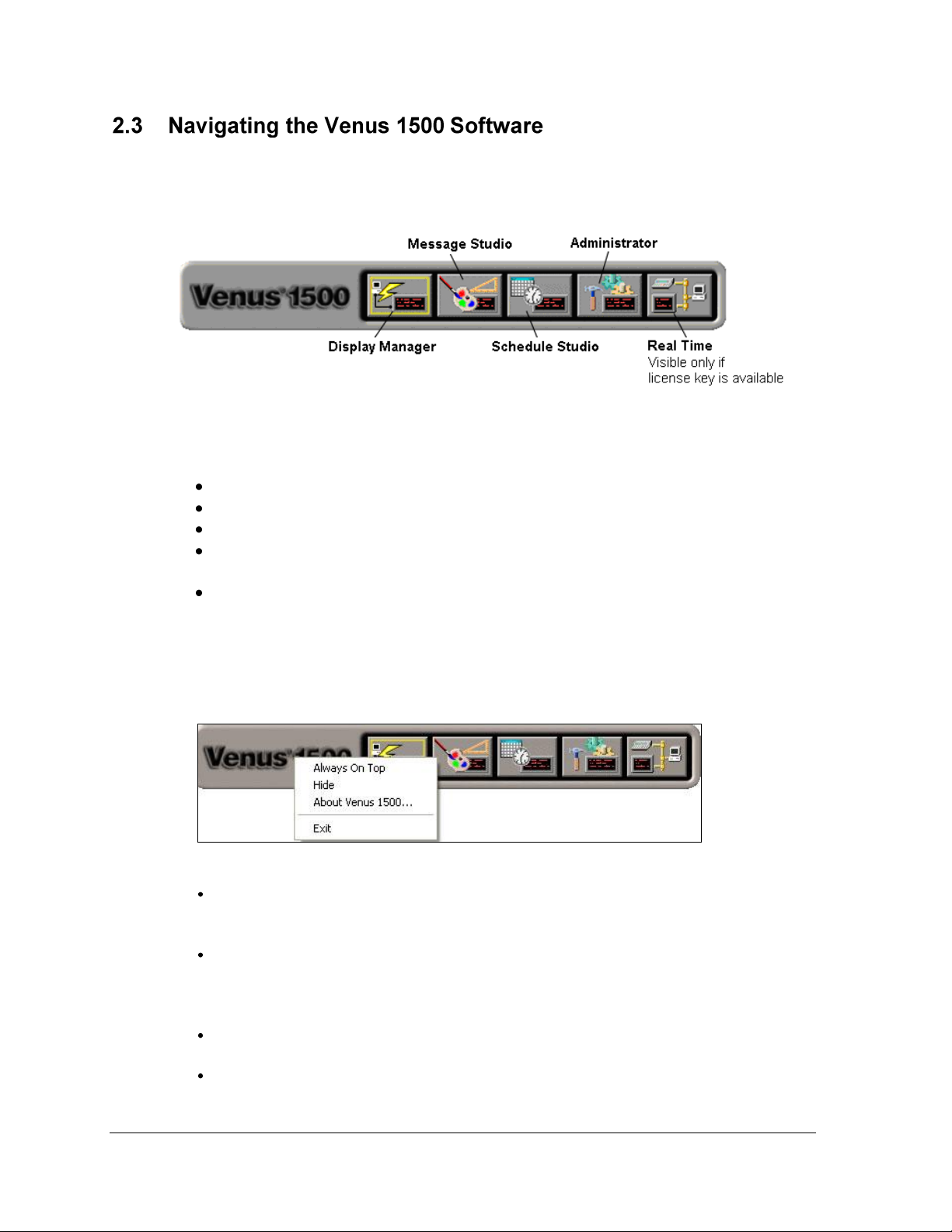
Figure 4: Right-click Menu
When the Venus 1500 software program starts, a ―shell‖ program loads. Refer to Figure 3.
Each component of the software (Message Studio, Schedule Studio, etc.) is launched from this
program. Click on the appropriate shell button to activate the desired component.
The Venus 1500 Shell consists of five buttons:
Display Manager sends content to and from the display.
Message Studio designs text and/or animated messages for the display.
Schedule Studio assigns start and stop dates and times to messages.
Administrator sets up the software to create messages and to communicate with the
sign.
Real Time displays data from external sources that output Daktronics standard real-
time data protocols. Note: Real Time will only appear if the software key is present
and is installed on Windows 2000 or XP Home/Professional.
Right-clicking the left side of the Venus 1500 Shell program brings up a menu with four
selections: Always On Top, Hide, About Venus 1500…, and Exit. Refer to Figure 4.
Getting Started
Always On Top places the Venus 1500 Shell program on top of all other programs
when navigating the desktop. The shell will always be visible when this menu item is
checked. Click this item to uncheck it and turn this feature off.
Hide completely hides the shell program when it is running (it is similar to
minimizing). The Venus 1500 Shell program has an icon in the system tray. To see the
program when the shell is hidden, double-click the shell icon, or right-click the icon
and select Restore on the menu that appears.
About Venus 1500… shows the About Venus 1500 dialog (Figure 2). Click OK to exit
this dialog.
Exit closes the Venus 1500 Shell program but will not close any other Venus 1500
program that may be running.
Page 19
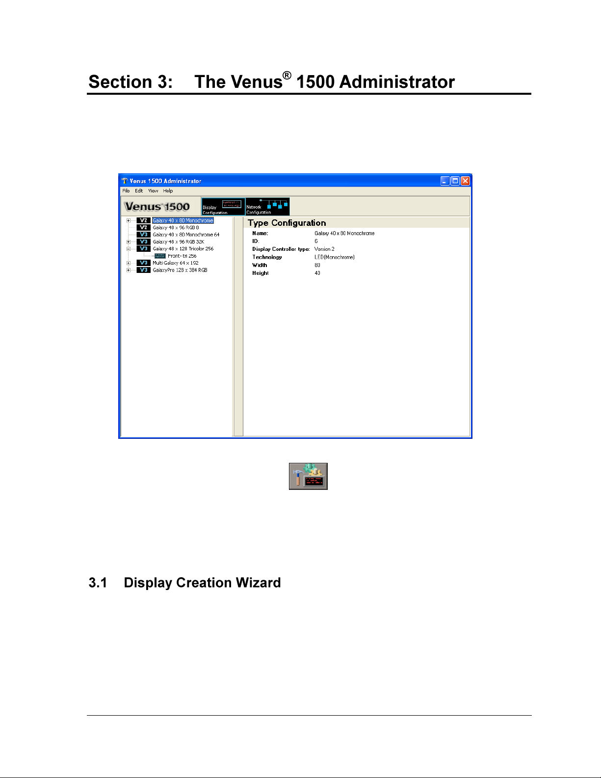
Figure 5: Venus 1500 Administrator – Display Configuration
The Venus 1500 Administrator is used to configure displays, display types, display groups, and
networks. Refer to Figure 5. The Administrator is also used to test the network, set up text filters,
configure the message database, and apply zoning restrictions.
To activate the Venus 1500 Administrator, click from the Venus 1500 Shell.
The screen is divided into two areas. When Display Configuration is selected, the left column will list
all of the currently configured display types. When Network Configuration is selected, the left
column will list all of the currently configured networks. The right side of the screen displays the
configuration details for the currently selected display or network.
Display Wizard is the recommended way to configure new networks, displays, and display
types, since it provides a systematic process for configuration. Refer to Tutorial 1: How to
Configure a Network and Display with the Display Wizard.
Note: It is also possible to configure networks, displays, and display types manually by
following the instructions in the following sections: 3.2 Network Configuration, 3.3 Display
Configuration, and 3.4 Display Type Configuration.
The Venus 1500 Administrator 5
Page 20
6
A network consists of multiple displays connected to each other. Up to 240 Venus 1500-
controlled displays can exist on one network.
When is selected, a network may be configured for communicating with
displays. The Network Configuration screen provides the tools to add a network, edit an
existing network, or remove a network. Refer to Section 3.1 Display Creation Wizard for the
recommended way of configuring a network.
Note: Manual Display Creation is an alternative to using the Display Wizard to
configure networks. Instructions for this process are available in Tutorial 2: How to
Configure a Network Manually.
Three different types of networks exist and are explained in the following list:
Direct Network indicates that a serial connection exists between the PC and the
display(s).
Dial-up Network indicates that an analog modem is used to communicate with the
display.
TCP/IP Network indicates a connection across a network using the TCP/IP protocol.
TCP/IP must be installed and correctly configured for the computer that has the
Venus 1500 software installed. All serial server or display addresses must be
static or use a fully qualified DNS name. Contact your system administrator to
obtain a static IP address or DNS name.
In some instances, a TCP/IP connection requires a serial server device connected
to an Ethernet network for communication to displays. The TCP/IP Address is
the address of the serial server on the Ethernet network. For a Lantronix™ serial
server, the TCP/IP Address is the address that was applied to the device when it
was configured. If a Lantronix serial server is being used, refer to Daktronics
manual ED-9623 for MSS-1 or MSS-100 and ED-12850 for the UDS-1100
instructions on configuring the serial server and assigning a static IP address. The
IP address of the serial server must be set in the TCP/IP network in the Venus
1500 software.
Refer to Tutorial 5 for instructions on adding, editing, and deleting networks.
The Venus 1500 Administrator
Page 21
Selecting enables displays and groups to be added, edited, and deleted.
Note: Confirm the display size, technology, and color of the display before configuring the
Venus 1500 Control System. Incorrect configuration settings may cause unwanted display
results. Refer to Section 3.1 Display Creation Wizard for the recommended method of
configuring a display.
Manual Display Creation is an alternative to using the Display Wizard to configure
displays. Instructions for this process are available in Tutorial 3: How to Configure a
Display Manually.
Refer to Tutorials 6 and 7 for instructions on editing and deleting displays.
A display group is a collection of displays that are the same display type (refer to Section
3.4). A group allows multiple displays to be selected in Display Manager. This allows
communication tasks to be easily applied to a single group of displays. Note: A group is not
required for sending data to the display. Refer to Tutorial 8 for instructions on creating a
group of displays.
Note: Display types must be configured and displays added before this option can be used.
Refer to Section 3.4.
Display type refers to the model of the display. A display type may be Galaxy®, DataTrac®,
or InfoNet®, for example. In addition, Galaxy displays may be monochrome, tricolor, or RGB.
The display type information is necessary for proper configuration. Multi-Galaxy display
type refers to the displays that include two different LED types in the same display (example:
one monochrome and one tricolor).
The number of display types that can be configured in the system is virtually unlimited. Refer
to Section 3.1 Display Creation Wizard for the recommended way of configuring a display
type.
Manual Display Creation is an alternative to using the Display Wizard to configure
displays types. Instructions for this process are available in Tutorial 4: How to
Configure a Display Type Manually.
Refer to Tutorial 9 for instructions on adding a multi-Galaxy display type.
Refer to Tutorial 7 for instructions on how to remove a display type.
The Venus 1500 Administrator 7
Page 22
8
Security options sets up a password for the display. The password is then stored in the
display’s memory and is verified every time the software communicates to the display. Refer
to Tutorial 10 for instructions on setting security options.
If the password is forgotten, it is necessary to access the internal components of the display to
reset the security function. Take care to remember the password.
Note: Password security can be activated for Version 3 displays only.
The operator can specify default settings for timeouts, maximum retries, and disconnect time
for each of the network types. Refer to Tutorial 11 for instructions on modifying
communication defaults. The following terms are used in the Communication Defaults
dialog:
Communication Timeouts is the maximum amount of time allowed between retries
when establishing a connection before the software times out the process.
Maximum Retries refers to the number of attempts made to connect to a display.
Disconnect Time is the maximum amount of time it will take for the control
computer to disconnect from the display after the last command was sent. Note: If
there is no communication with the display for the specified time, the control
computer will close the connection with the display.
Venus 1500 software contains a text filter that prevents specified words from appearing on
the display(s). To enable or modify this filter, select Text Filter Setup from the Edit menu in
the Venus 1500 Administrator. Refer to Tutorial 12 for instructions on customizing the Text
Filter.
Two filter lists can be enabled:
Default List protects against words identified in the FCC vs. Pacifica Foundation
(438 U.S. 726 [1978]) legal case. To view this list, click View Default List.
WARNING: The words in the Default List can be seriously offensive to many people. View
this list with the understanding that it is a filter system for the Message Editor program and is
not meant to be offensive.
Custom List protects against words identified by the operator.
The Venus 1500 Administrator
Page 23
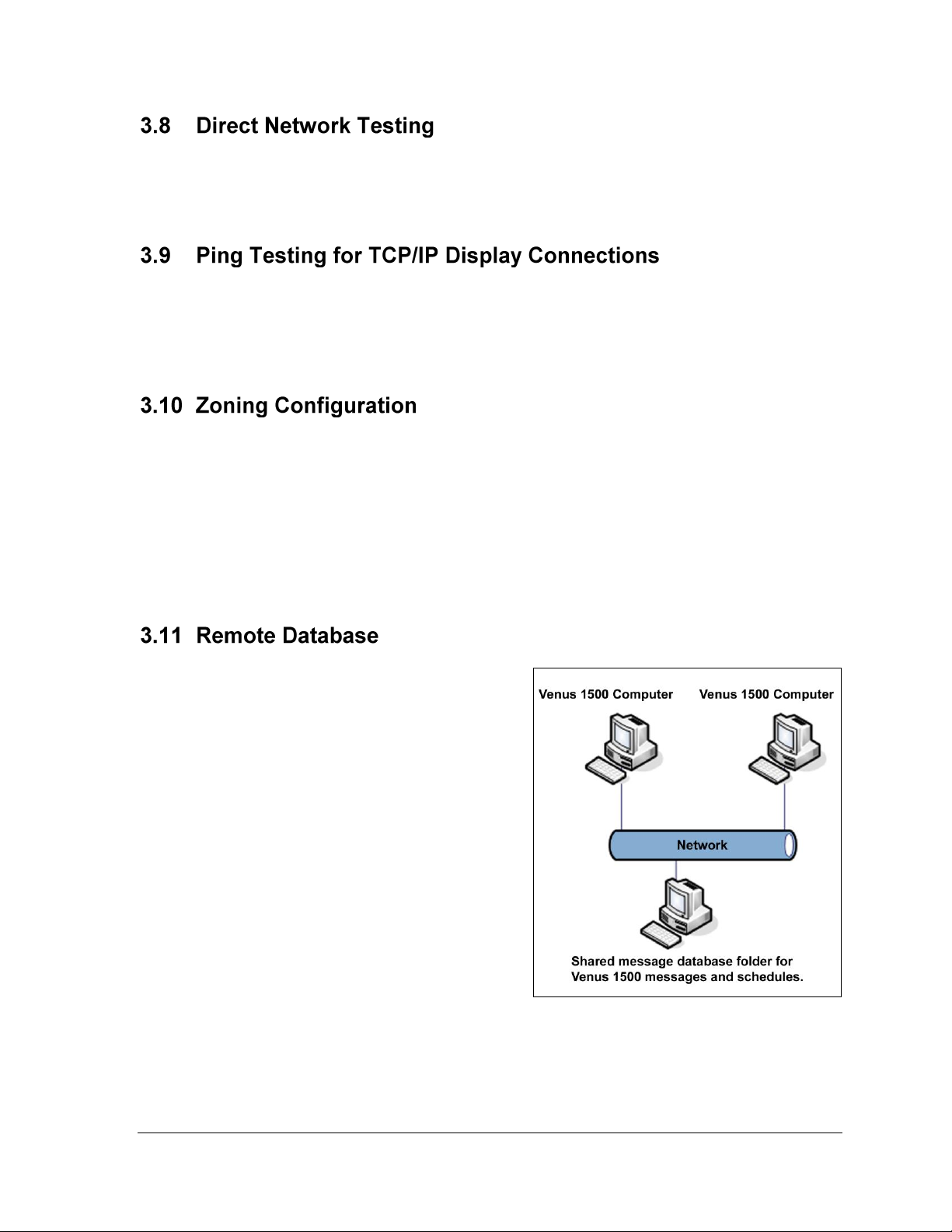
Figure 6: Shared Database
Direct network testing uses a loop-back box or adapter to test whether the serial port is
working and to determine that the communication cable has no physical breaks in it. Refer to
Tutorial 15 for instructions on testing the network.
The ping capability in the Venus 1500 is a troubleshooting tool for TCP/IP networks. This
feature allows the operator to ensure that the serial server or display on a TCP/IP network is
alive and working. Refer to Tutorial 15 for instructions on ping testing for TCP/IP display
connections.
Zoning Configuration is available for areas that have restrictions on the electronic messages
that are displayed. If a message contains restricted actions such as flashing when it is created,
the zoning restrictions will not allow that feature to be shown on the display. This feature will
prevent operators from inadvertently violating local zoning restrictions. However, while in
Message Studio, the messages will preview effects that the operator adds, but the effects will
not be visible on the display.
Refer to Tutorial 13 for instructions on customizing Zoning Configuration.
For locations that have multiple computers
with Venus 1500 installed, a remote database
can be configured for storing messages. This
allows messages to be shared between
computers without needing to copy the
messages from one computer to another. Refer
to Figure 6.
Note: This feature may not work if the
computer with the Venus 1500 software has an
operating system different from the remote
computer. For example, if the computer with
the Venus 1500 software installed is running
Microsoft Windows XP® and the remote
computer with the Remote Database is
running Microsoft Windows 98®,
communications will fail.
Refer to Tutorial 14 for additional information.
The Venus 1500 Administrator 9
Page 24
10
The following steps are necessary for setting up a remote database:
1. Click Venus 1500 Administrator from the Venus 1500 shell.
2. Select Edit > Database.
3. Select the Remote Database location by clicking on the browse button.
4. Browse to the new database location and click OK to select it.
5. Click OK to close the Remote Database dialog. A prompt will appear to move the
contents of the local database to the remote location.
Note: This is simply a sharing function and does not synchronize computers or displays in
any way. Any existing messages with the same names will be overwritten. It is best to set up
the remote database immediately before configuring displays and creating messages or
schedules.
Following this section are the tutorials for Administrator. Please refer to the tutorials for
directions on operating the Administrator part of the Venus 1500 software. The following is a
list of the tutorials:
1. How to Configure a Display and Network with the Display Wizard
2. How to Configure a Network Manually
3. How to Configure a Display Manually
4. How to Configure a Display Type Manually
5. How to Add, Edit, and Delete a Network
6. How to Edit a Display’s Configuration
7. How to Delete a Display or Display Type from a Network
8. How to Create a Group of Displays
9. How to Add a Multi Galaxy Display Type
10. How to Set Security Options
11. How to Modify Communication Defaults
12. How to Custom Configure - Text Filter
13. How to Custom Configure - Zoning Configuration
14. How to Custom Configure - Database
15. How to Test a Network
The Venus 1500 Administrator
Page 25
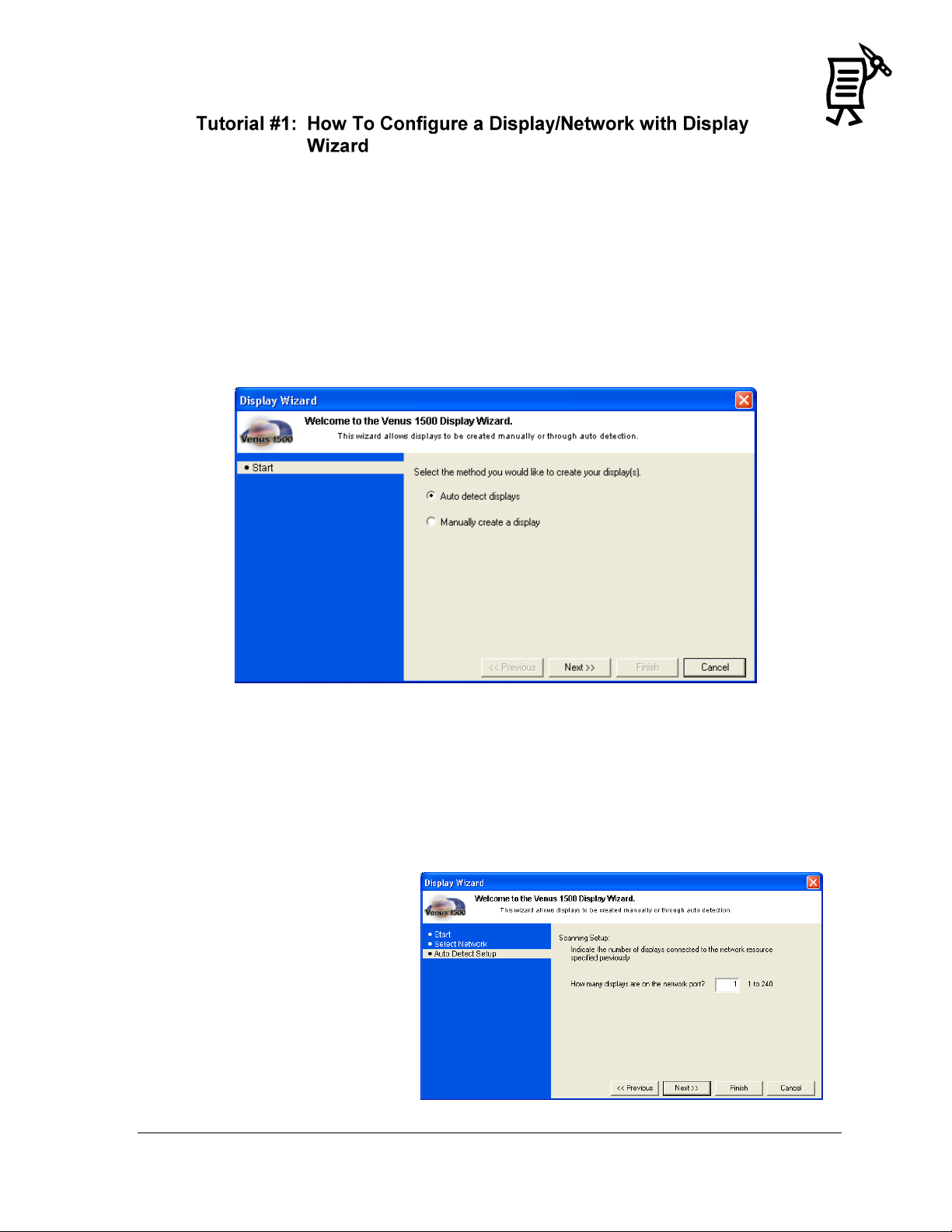
Figure 7: Display Wizard
Figure 8: Auto Detect Setup
NOTE: This feature will only work with the display controller when the power is ON.
The Display Wizard is the easiest way to automatically detect the displays that are connected
to the network source. This is the recommended detection method.
1. Click Display Wizard in the Edit menu of the Administrator.
2. Mark the Auto Detect option if not already marked. Auto Detect allows the software to
scan for the display’s address and automatically set up the necessary information. Refer
to Figure 7.
3. Click Next.
If a network has already been created, follow steps 4-10. If a network has not been created, go
to step 11.
4. Select a communications port from the down arrow under Select a list of existing
configured network resources. Click Next.
5. Type in the number of displays which the Display Wizard should detect in the
network. (The maximum number of displays on a network is 240.) Click Next. Refer to
Figure 8.
The Venus 1500 Administrator 11
Tutorial
Page 26
12
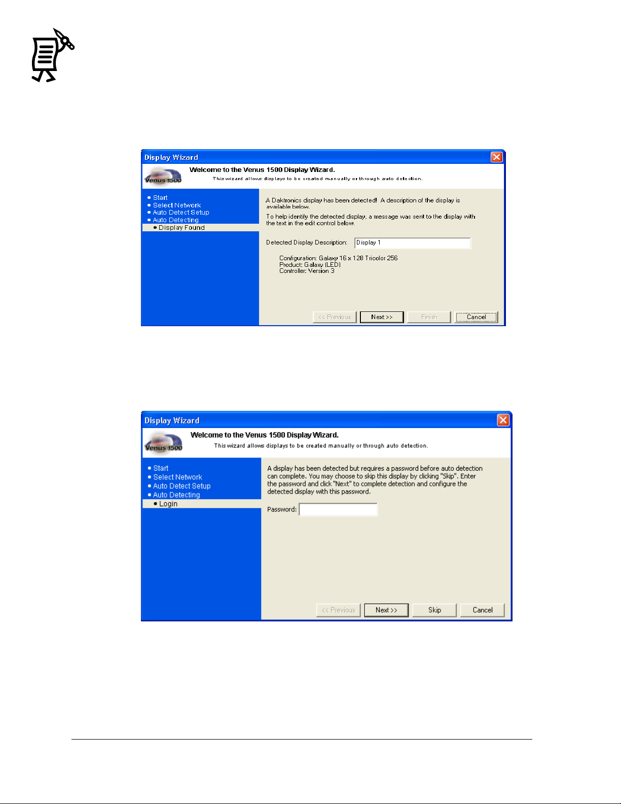
Figure 9: Detected Display Description
Figure 10: Security Option
6. When the Auto Detecting is completed, the Display Wizard will show the Display
Description. At this point, it is possible to rename the display to make it easily
identifiable. To do this, click in the Detected Display Description box, highlight the
current name and enter the desired name. Refer to Figure 9.
7. If the Security Option is enabled on the display, a window will appear asking for the
password to be entered before completing the Auto Detect (Figure 10).
The Venus 1500 Administrator
Tutorial
Page 27
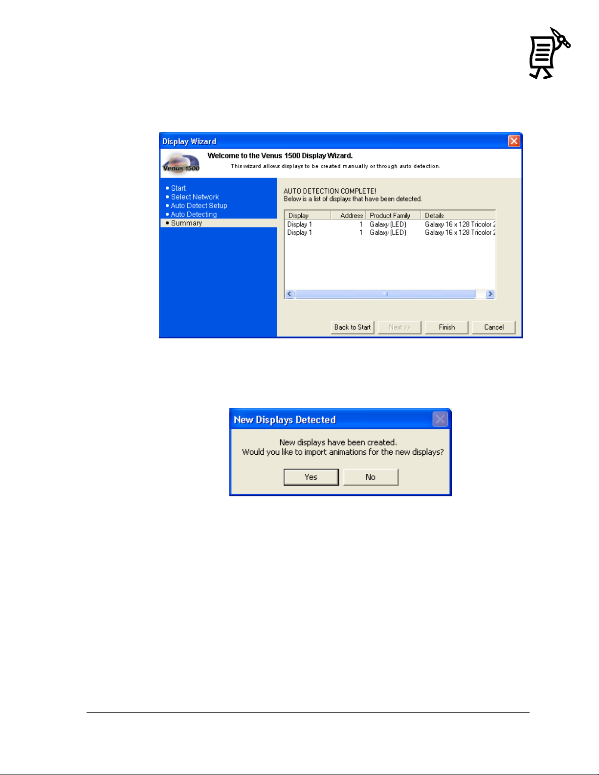
Figure 11: Display Summary
Figure 12: Import Animations
8. Once the Display Wizard has finished scanning the network, it will show all the
displays found on that network (Figure 11). Click Finish to save the information and
begin communicating with the display(s) or click Back to Start to configure another
display.
9. Once the display is configured, click the Finish button. To import animations now,
insert the Venus 1500 Installation CD, and click Yes. Click No to void the import
(Figure 12).
10. If animations are available for this display type, they are imported automatically.
The animations will be added to the Animate folder in the Message Studio.
The Venus 1500 Administrator 13
Tutorial
Page 28
14
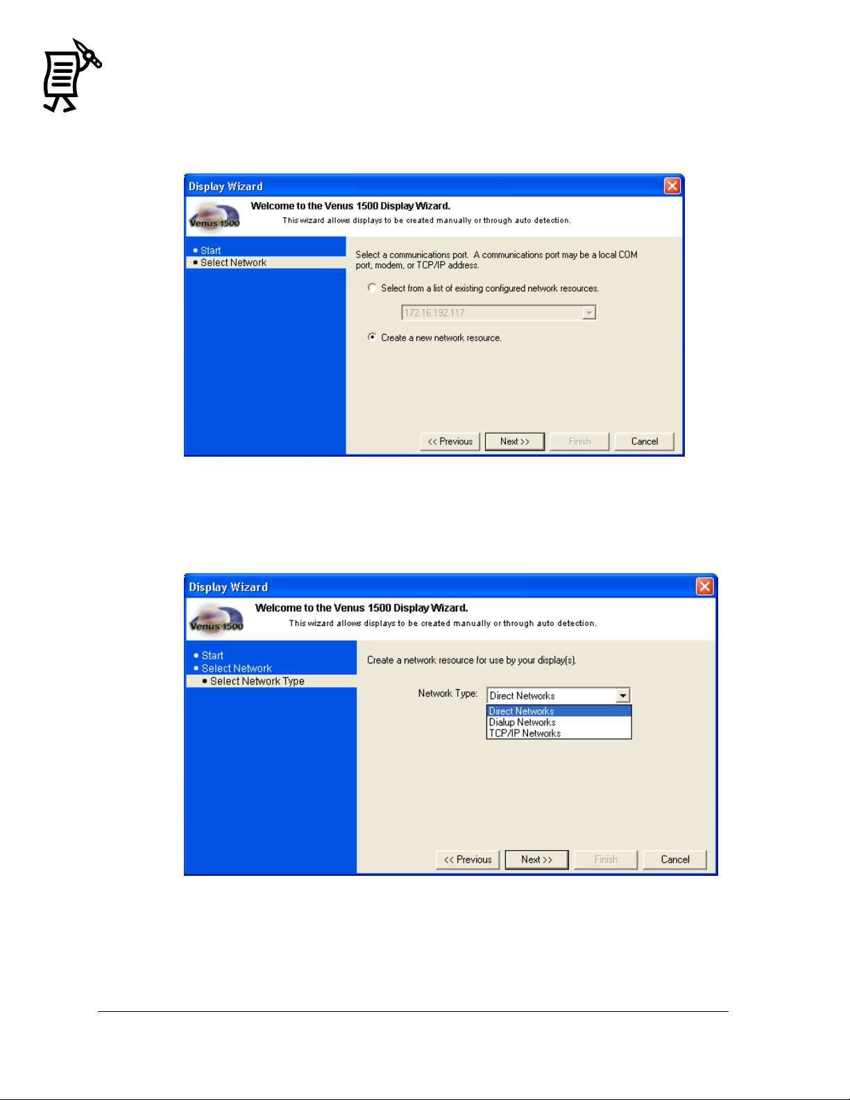
Figure 13: Display Wizard Network Configuration
Figure 14: Network Type Configuration
If a network has not been created, follow steps 11-19.
11. Select Create a new network resource, and click Next (Figure 13).
12. Choose which type of network to create: Direct, Dial-up, or TCP/IP. Select the type by
clicking on the down arrow next to the Network Type box (Figure 14).
13. Click Next.
The Venus 1500 Administrator
Tutorial
Page 29
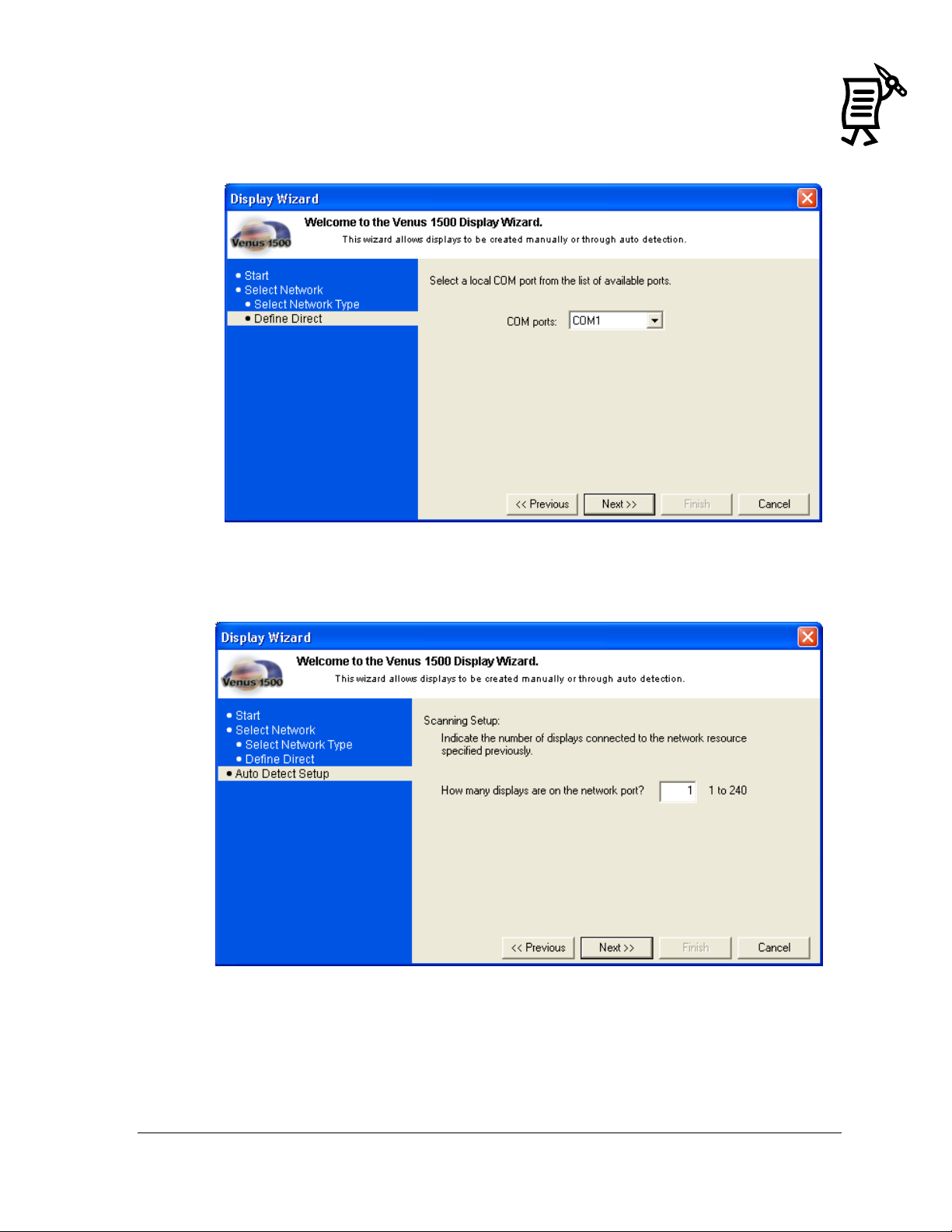
Figure 15: COM Port Selection
Figure 16: Auto Detect Setup
14. Select a local COM port from a drop-down list of available ports (Figure 15) and click
Next.
15. Type in the number of displays on the network port, and click Next.
The Venus 1500 Administrator 15
Tutorial
Page 30
16
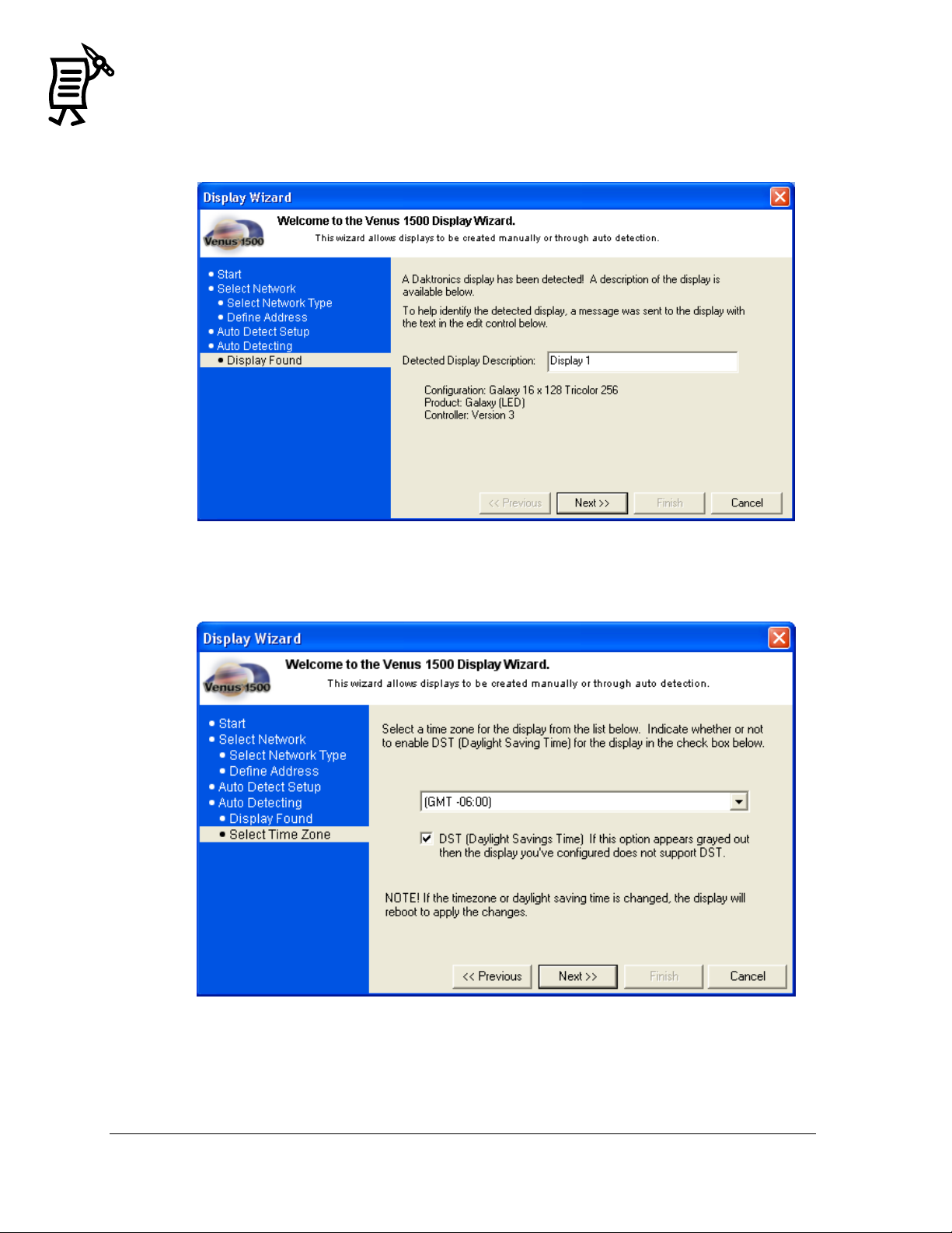
Figure 17: Display Found
Figure 18: Select Time Zone
16. The Display Wizard will then auto-detect the ports and show a window with the
information of the display(s) found. Refer to Figure 17. Click Next.
17. Choose a time zone for the display and click Next (Figure 18).
The Venus 1500 Administrator
Tutorial
Page 31

Figure 19: Auto Detection Summary
18. The Display Wizard will show an auto-detection summary of the display that was
found (Figure 19). Click Finish.
19. To import animations now, insert the Venus 1500 Installation CD and click Yes. Click No
to void the import. Refer to Figure 12. The animations will be added to the Animate
folder in the Message Studio. If animations are available for this display type, they will
be imported automatically.
The Venus 1500 Administrator 17
Tutorial
Page 32

18
Figure 20: Network Communications
Figure 21: Network Configuration
Configuring the network determines communication between the computer and display. The
following sections show the three ways to configure a network:
Direct Network Configuration
Dial-up Connection
TCP/IP Connection
Note: Refer to Tutorial #4 for directions on configuring a network using the recommended
Display Wizard.
1. Activate the Venus 1500 Administrator by clicking on the Administrator button
from the Venus 1500 Shell. Refer to Figure 20.
2. Click the Network Configuration button to activate the Network
Configuration screen.
3. Right-click Direct Networks on the left side of the screen and select New, or in the Edit
menu, select New > Network.
4. When the Network Configuration window opens, type a Network Name in the
The Venus 1500 Administrator
Tutorial
description field (Figure 21).
Page 33

Figure 22: Dialup Network Configuration Box
5. In the Network Type field, choose Direct Networks from the down arrow.
6. Click the down arrow next to COM ports.
7. Select the port to which the serial cable is connected from the listing of installed ports.
(The default port is COM1.)
8. Click OK to save the settings and close the Network Configuration dialog box.
9. The new configured network will appear under the network type that was selected on the
left side of the Network Configuration screen. If the configured network cannot be seen,
click on the plus sign to open the configured networks.
10. The network configuration information will appear on the right side of the screen.
A dial-up connection uses a modem to communicate with the display or network. A modem
must already be installed and operating properly prior to selecting a dial-up connection type.
If more information is needed regarding modem installation, consult the manual
accompanying the modem or contact the modem’s manufacturer.
If modem communication problems exist, ensure that the most recent modem drivers for the
operating system are installed and are properly configured.
1. Click the Network Configuration button located near the top of the
screen in the Venus 1500 Administrator.
2. Right-click Dialup Networks on the left side of the Network Configuration screen.
3. Click New…
4. In the Network Name field, enter a name for the new network. Refer to Figure 22.
5. Click the down arrow next to Modem for a list of currently installed modems.
6. Select the modem to use. If the modem list is empty, check under Modems in the Windows
Control Panel to ensure a modem has been installed for use by the operating system.
7. Click OK to save the changes and close the Network Configuration dialog box.
8. To use this type of connection, select Dialup Networks in the Network Type field, if it is
not already selected.
9. Click the down arrow next to Modem. A list of currently installed modems will appear.
10. Click OK to save the new network and close the Network Configuration dialog box.
The Venus 1500 Administrator 19
Tutorial
Page 34

20
Figure 23: TCP/IP Network Configuration
Figure 24: TCP/IP Network Configuration Box
Click the Network Configuration button located near the top of the Venus
1500 Administrator screen.
1. Right-click TCP/IP Networks on the left side of the Network Configuration screen.
2. Click New…
3. Enter a name for the new network in the Network Name field. Refer to Figure 24.
4. Enter the TCP/IP address or fully qualified DNS name for the serial server. If an IP
address is being used, ensure the period marks appear between each set of numbers in
the address.
5. If a serial server socket is 3001, leave the Use Default checked. Otherwise, uncheck Use
Default and enter the socket number in the corresponding box.
6. Click OK to save the new network and close the Network Configuration.
The Venus 1500 Administrator
Tutorial
Page 35

Figure 25: Display Configuration
A display cannot be programmed if a network is not configured previously. Refer to Tutorial
#1 for instructions on configuring a network. Configuration settings may vary for every
installation.
Note: If a display has been configured through the Display Wizard, then the following steps
are unnecessary. Refer to Tutorial #4 for directions on configuring a display using the
Display Wizard.
The Manual Display Configuration is used to set up communication with displays. The
following steps are instructions for configuring a display:
1. Select the Display Configuration button in the Venus 1500
Administrator.
2. From the Edit menu, select New > Display. The Display Configuration dialog box
appears (Figure 25).
The Venus 1500 Administrator 21
Tutorial
3. Enter a Description for the display. This can be a number or a brief description of its
location. In the example, the display was named ―West Lot.‖
4. Enter ―1‖ for the display’s network Address.
5. From the drop-down menu for Display Type, choose the appropriate type.
6. Select the type of network that has already been configured.
7. If the display has a modem, enter the Phone Number of the modem. If not, the field
will be disabled (grayed).
8. Select the correct time zone for the display by clicking on the down arrow.
9. If restrictions need to be applied, check the restrictions box. Refer to Tutorial #13 for
information on setting restrictions.
10. Select the Daylight Saving Time box if the time needs to be adjusted automatically
during this period of the year.
Page 36

22
11. Click Security Options to set up a security password. After a password is entered,
click OK in the Security Options dialog box.
12. Click OK in the Display Configuration dialog box to save the new display
configuration.
13. To import animations now, insert the Venus 1500 Installation CD and click Yes. Click
No to void the import.
14. Close the Venus 1500 Administrator configuration window by selecting Exit from the
File menu or clicking the close button on the top right corner of that screen.
The Venus 1500 Administrator
Tutorial
Page 37

This tutorial will give instructions on manually configuring a display type.
1. Click to activate the Display Configuration screen.
2. From the Edit menu, select New > Display Type. The Display Type Configuration dialog
box will appear. Refer to Figure 26.
Figure 26: Display Type Configuration
3. Click the down arrow next to the Display Controller Type and select the version of Venus
1500 controller the display will use.
4. Click the down arrow next to the Technology box and select the appropriate type.
5. Select the appropriate Height and Width from the corresponding drop-down menus.
The numbers represent the pixel size of the display.
6. Select the appropriate item in the Color Depth field. Note: Only valid sizes and colors
for the current display technology will be available for selection.
7. Click OK to save the settings.
The Venus 1500 Administrator 23
Tutorial
Page 38

24
Figure 27: Select a Network
Figure 28: Network Configuration Dialog
Figure 29: Removing a Network Warning
Refer to Tutorial #2: Configuring a Network.
1. Right-click on a network name on the left side of the Network Configuration screen.
2. Click Edit…in the pop-up menu.
OR
1. Activate the Edit menu.
2. Select Edit > Network.
3. Select the Network to be changed
in the Select a Network window.
Refer to Figure 27.
When the Network Configuration dialog
box appears, change the information as
needed (Figure 28).
1. Right-click a network name on the left side of the screen.
2. Select Delete from the pop-up menu.
3. A dialog appears requesting a confirmation of the deletion (Figure 29). Click Yes to
delete the network or No to cancel.
WARNING: Deleting a network can leave displays without communication links.
The Venus 1500 Administrator
Tutorial
Page 39

Figure 30: Edit Display
Figure 31: Edit Display Configuration
To modify the settings of an existing display or display group:
1. Right-click on a display or group name on the left side of the Display Configuration
screen.
2. Click Edit…in the pop-up menu.
OR
1. Select Edit > Display (to edit a single display) or Display Group (to edit a group).
2. Select the display to edit in the Select a Display window. Refer to Figure 30.
3. Edit the information as needed in the Display Configuration dialog box (Figure 31).
4. Click OK.
The Venus 1500 Administrator 25
Tutorial
Page 40

26
Figure 32: Delete Display Warning
1. Right-click on the display name or display type on the right side of the Administrator
screen.
2. Select Delete on the pop-up menu. A dialog box appears requesting a confirmation of
the deletion. Refer to Figure 32.
3. Click OK to delete the display or display type or click Cancel to leave the display or
display type.
The Venus 1500 Administrator
Tutorial
Page 41

A group of displays is a collection of displays of the same display type that can receive Venus
1500 commands simultaneously. This option can be used to send the same message(s) at the
same time to more than one display of the same type. A group is not required for sending data to
the display.
NOTE: Display types must be configured and displays added before this option can be used.
To create a new group:
1. From the Edit menu, select New > Display Group. The Display Group Configuration
dialog box appears. Refer to Figure 33.
Figure 33: Display Group Configuration
2. Enter a name for the group in the Description field.
3. Select the group’s display type. A list of available displays appears in the left half of the
dialog box.
4. Highlight the display(s) to be included in the group and click Add>>. The display(s)
are added to right column called Member Displays.
5. To remove a display, highlight the name under Member Displays and click
<<Remove.
6. Click OK to save the display group or choose Cancel to discard all settings and exit the
dialog box
The Venus 1500 Administrator 27
Tutorial
Page 42

28
Figure 34: Multi Galaxy Display Configuration
This option is only available with Venus 1500 Version 3 displays.
To add a multi-Galaxy display type:
1. Click to activate the display configuration screen.
2. From the Edit menu, select New > Display Type. The Display Type Configuration dialog
box appears. Refer to Figure 34.
3. In the Display Controller Type menu, select Version 3.
4. Click the down arrow next to the Technology box and select Multi Galaxy (LED).
5. Under Galaxy Technology, select whether the Multi-Galaxy display is configured left to
right or top to bottom.
6. Set the pixel matrix size for View 1 (display section) by clicking on the down arrow
next to the Height and Width fields.
7. Click on the down arrow next to Color Depth and select the color capabilities for View 1.
8. Click on the Pixel Pitch field and select the spacing between each pixel in the matrix for
View 1.
9. Repeat steps 4 – 7 to configure View 2.
10. Click OK.
The Venus 1500 Administrator
Tutorial
Page 43

Figure 35: Security Options Button
Figure 36: Password Entry
Password security can be activated for Version 3 displays only. This allows a password to be
set up for the display. The password is then stored in the display’s memory and is verified
each time the software communicates to the display. If the password is forgotten, it will be
necessary to access the internal components of the display to reset the security function. Take
care to remember the password.
To enable the Security option:
1. Right-click on the desired display from the Display Configuration list and a pop-up
menu will appear.
2. Click Security Options and the corresponding window will appear (Figure 35).
3. Select the Enable Security box and type in the desired password in the New Password
field (Figure 36). Retype the password in the Confirm Password field. Passwords in both
fields must match and are case sensitive.
When the Security Option is enabled, the user will see two blinking pixels in the bottom right
hand corner when the display is blanked. It
may be necessary to update the firmware at
the display in order for the Security Option to
work.
The Venus 1500 Administrator 29
Tutorial
Page 44

30
Communication Timeouts
Maximum Retries
Disconnect Time
Direct: 60 Sec
Direct: 10
Direct: 90 Sec
Dial Up: 30 Sec
Dial Up: 10
Dial Up: 30 Min
TCP/IP: 30 Sec
TCP/IP: 10
TCP/IP: 90 Sec
Task Failure: 10 Min
Figure 37: Communication Defaults
It is also possible to specify default settings for timeouts, maximum retries, and the
disconnect time for each of the network types. Use the following steps to modify the
communication defaults:
1. From the Edit menu in Administrator,
select Defaults.
2. Change the settings as desired using the
arrows next to each field or by
highlighting the number and typing the
new value. Refer to Figure 37.
Communication Timeouts is the
maximum amount of time allowed
between retries for a connection to be
established before the software times
out the process.
Maximum Retries is the maximum
amount of attempts to connect to a
display.
Disconnect Time is the maximum
amount of time it will take for the
control computer to disconnect from
the display after the last command
was sent to the display.
3. Click Apply to save the settings but keep
the Communication Defaults dialog box
open. Click OK to save the settings and close the dialog box. Cancel will abort all
changes and exit the dialog box.
The minimum value for all fields is 1. The maximum values for each field are as follows:
The Venus 1500 Administrator
Tutorial
Page 45

Figure 38: Text Filter Setup
This section will provide instructions on configuring the text filter.
1. Click on the Administrator button in the Venus 1500 Shell.
2. From the Edit menu, select Text Filter Setup.
Note: Two filter lists can be enabled: Default List and Custom Word or Phrase list. The Default
List is a default profanity filter that protects against words identified in the FCC vs. Pacifica
Foundation (438 U.S. 726 [1978]) legal case. The custom filter protects against words identified
by the operator.
To view the default list, click View Default List. Refer to Figure 38.
WARNING: The words in the Default List can be seriously offensive to many people. View
this list with the understanding that it is a filter system for the Message Editor program and is
not meant to be offensive.
The Venus 1500 Administrator 31
Tutorial
3. Select the box next to the desired filter. A check mark indicates the filter is enabled.
4. Select Match Whole Word Only to filter the exact words or phrases in these lists. (For
example, if the word ―and‖ was added to the Custom List, the word ―handle‖ will be
filtered if Match Whole Word Only is unchecked as it contains the word ―and.‖ It will
not be filtered if the box is checked.)
Page 46

32
5. To add new words to the custom filter feature, ensure that the Use Custom List box is
checked.
6. Next, enter the new word in the field next to the Add button. Click Add to save the
word to the list. The word will appear in the Custom Word or Phrase column.
7. To remove a word from the list, click on the desired word and then click Remove. The
word will disappear from the column.
8. Click OK to save the settings and return to the Venus 1500 Administrator window.
The Venus 1500 Administrator
Tutorial
Page 47

Figure 39: Zoning Configuration
This section will give instructions on setting the zoning configuration.
1. In the Venus 1500 Administrator, click Edit > Zoning Configuration. The Zoning
Configuration dialog will appear (Figure 39).
2. Click the desired Restrictions to be enforced.
a. Minimum Hold Time sets the absolute minimum amount of time that a
message can be displayed. This applies only to Version 3 displays.
b. No Flash prevents any part of the message from flashing when displayed.
c. No Effects cancels out all effects that may have been applied to the message;
this includes the flashing function.
3. Select which of the three Enforcement levels should be applied.
a. Ignore Restrictions will void any restrictions that have been set for all
displays on the network.
b. Sign by Sign Basis allows the user to choose which displays will respond to
the restrictions set for that sign. Note: If Sign by Sign Basis is selected,
restrictions are enabled in the Display Configuration dialog.
c. Always Enforce enforces all restrictions on all displays at all times.
4. Click OK to save the settings and to close the window or click Cancel to void the action
and return to Venus 1500 Administrator.
The Venus 1500 Administrator 33
Tutorial
Page 48

34
Figure 40: Display Configuration - Restrictions
To enable restrictions for a particular display:
1. Click the Display Configuration button in the Venus 1500 Administrator.
2. Select the display type and right-click the desired display.
3. Select Edit from the menu. The Display Configuration dialog will appear (Figure 40).
4. Select Restrictions (note the arrow) and click OK.
The Venus 1500 Schedule Studio
Tutorial
Page 49

Figure 41: Select Database Window
Figure 42: V15Admin Prompt
1. In the Venus 1500 Administrator, select Edit > Database.
2. The Select Database window will open to allow the selection of either Local Database or
Remote.
This feature will not work if the main computer is operating on a Windows 2000 or XP
platform and the remote database computer is operating on a Windows 98 platform.
This is a sharing function and does not synchronize computers or displays in any way. Any
existing messages with the same names will be overwritten. It is best to set up the remote
database immediately before configuring the displays and before creating messages.
1. Click the Venus 1500 Administrator.
2. Open the Edit menu and select Database. Refer to Figure 41.
3. Select Remote Database and find its location by clicking on the Browse button.
4. Browse to the new database location and click OK to select it.
5. Click OK to close the Remote Database dialog.
6. A prompt will appear to move the contents of the local database to the remote location.
Click Yes to move the contents or click No to cancel the move. Refer to Figure 42.
The Venus 1500 Administrator 35
Tutorial
Page 50

36
Figure 43: Ping Testing
Network testing requires the use of a loop-back box or adapter. This box/adapter connects
the serial port transmit and receives pings to determine if the serial port is working and no
physical breaks are present in the communication cable. It will not determine signal
polarity. It is possible for the loop-back test to work and still not receive communication
resulting from improper wiring.
1. In the Venus 1500 Administrator, click on .
2. Right-click on the desired network to activate the pop-up menu and then select Test…
The Network Testing dialog box appears.
3. Attach the loop-back box/adapter and click Test to begin testing the network. In the
Received area of the dialog box, the following results may be returned:
a. The test was successful if the same text appears in both the Sent area and in the
Received area.
b. ―No response‖ indicates a break in the cable, a bad serial port, or a bad signal
converter (if used).
c. ―Connection failure‖ indicates the test was unable to connect to the serial server
if connecting to the display via a TCP/IP connection.
d. When the test is complete, click Close to return to the Venus 1500 Administrator.
The ping capability in the Venus 1500 is a troubleshooting tool for TCP/IP networks. This
feature allows the user to ensure that the serial server on a TCP/IP network is alive and
working.
To use the Ping feature:
1. In the Venus 1500 Administrator, click on Network Configuration.
2. Double-click on TCP/IP Networks. Right-click on the desired network and a pop-up
menu will appear.
3. Click Ping. The controller will send out a signal to the serial server. If the serial server
is functioning properly, it will send back a signal to the controller. This will be
displayed similar to Figure 43.
4. Click OK to accept the results and close the Ping
Data window.
The Venus 1500 Administrator
Tutorial
Page 51

Figure 44: Venus 1500 Message Studio
The Venus 1500 Message Studio creates the messages that will appear on the displays. This section will
give instructions on creating basic text messages, animated graphics, and effects for a display.
To activate the Venus 1500 Message Studio, click on the Venus 1500 Shell. In the Venus 1500
Message Studio, text and graphics are entered into ―frames.‖ One or more frames create a message.
Thumbnails of existing frames for the current message are displayed along the right side of the
screen. Refer to Figure 44.
A variety of toolbars are available to create messages. These toolbars are labeled in Figure 44. Each
tool of the toolbars is described in the sections following.
The Venus 1500 Version 3 software controls multiple display types, which are Galaxy, Sunspot, Glow
Cube, Infonet, Datatrac, Multi-Galaxy, and GalaxyPro. The display type will enable different message
options in the Venus 1500 Message Studio.
The Venus 1500 Message Studio 37
Page 52

38
Figure 45: Standard Toolbar
The Message Studio contains numerous toolbars that assist in creating messages.
The Standard Toolbar offers basic tools for creating new messages, opening existing
messages, saving files, printing, cutting, copying, and pasting elements. Below are
descriptions for the buttons on the Standard Toolbar:
Create new message opens a new message file.
Open existing message opens an existing file.
Save active message saves the active open file.
Save all open messages saves all open files.
Print active message prints a paper copy of a sequence of all frames or of
selected frames.
Cut selection to clipboard cuts a selection and places that selection on the
clipboard.
Copy selection to clipboard copies a selection and places that selection on the
clipboard.
Paste content from clipboard pastes the contents from the clipboard into the file.
Undo action from history reverses the last action.
Redo action from history reverses the undo action.
Increase message scale enlarges the view of the frame.
Decrease message scale reduces the view of the frame.
Zoom field allows the operator to enter a specific zoom percentage.
Justify left positions the text to the left of the frame.
Justify center positions the text in the center of the frame.
Justify right positions the text to the right of the frame.
Justify top positions the text to the top of the frame.
Justify middle positions the text to the middle of the frame.
The Venus 1500 Message Studio
Justify bottom positions the text to the bottom of the frame.
Check spelling activates the spell check.
Help displays the electronic copy of this manual.
Page 53

Figure 46: Venus Font Text Toolbar
Figure 47: True Type Font Text Toolbar
The Font Information toolbars select the font used on frames, including font size, appearance,
and other properties. The toolbar varies depending on whether the message is in a text or a
graphic frame and whether the operator is using the True Type fonts or the Venus fonts.
The Venus Font text toolbar (see Figure 46) is used to type text in messages when not in a
graphic page. In graphic pages, the user has the ability to use the Venus Font text or the True
Type font text. To access the Venus Font text toolbar in graphic page, click on Add Venus
Font Text under the Text menu.
Below are descriptions of the buttons on the Venus Font Text toolbar:
Venus fonts menu lists the possible fonts for messages.
Text color allows the user to access the color palette for specific text colors.
Outline text outlines the text with a color of the user’s choice.
Shadow text shadows the text with a color of the user’s choice.
Flash text flashes text when specific text is highlighted.
The True Type font text toolbar (Figure 47) can be accessed when the user is in a graphic frame
and Add True Type Font Text is clicked in the Text menu.
Below are descriptions of the buttons on the True Type Font Text toolbar:
Windows
®
fonts menu lists the possible fonts for messages
with the True Type Font Text toolbar.
Font size allows the user to choose what size of font to use for messages.
Bold makes highlighted text bold.
Italic makes highlighted text italic.
Underline underlines highlighted text.
Text color allows the user to access the color palette for specific text colors.
Outline text outlines the text with a color of the user’s choice.
Shadow text shadows the text with a color of the user’s choice.
Smooth text smoothes the edges of the text or figures to make them appear
The Venus 1500 Message Studio 39
smoother.
Page 54

40
Figure 48: Frame Toolbar
Figure 49: Previewing Toolbar
The Frame Toolbar (refer to Figure 48) contains tools used to create and delete frames. The
Frame Toolbar is located in the upper-left part of the message studio screen.
Below are descriptions of the buttons on the Frame Toolbar.
Add new text frame adds a new frame for text.
Add new graphic frame adds a new frame for graphics.
Insert copy of current frame adds an exact copy of a frame within a sequence.
Delete current frame deletes a frame from a sequence.
The Previewing Toolbar (Figure 49) contains tools used to preview messages. The Previewing
Toolbar is located beneath the message creation area.
Preview frame plays the active frame on the monitor as it would appear on the
display.
Preview plays the active sequence of frames as they would appear on the
display.
Stop stops the currently playing message.
Pause pauses the currently playing message.
First frame changes the active frame to the first frame in the sequence.
Previous frame changes the active frame to the previous frame in the sequence.
The Venus 1500 Message Studio
Next frame changes the active frame to the next frame in the sequence.
Last frame changes the active frame to the last frame in the sequence.
Page 55

Figure 50: Brush Options
The Graphic Toolbar contains tools to edit graphics in messages. The Graphic Toolbar is located
on the left side of the Message Studio screen.
Object selection tool allows the user to select individual images, text, or an
entire graphic to move in the message frame. The user is also able to select
various layers of the frame by clicking in the desired area.
Create new Venus text box activates the custom fonts created specifically for
use with Daktronics displays. Text may be edited in a variety of ways, such as
changing the color of certain words or changing the font size of one line.
Create new True Type text box activates Windows fonts. They may be used
to create text messages similarly to the Venus fonts. However, text colors,
sizes, and other characteristics may be applied only to the complete text and
not to specific words or lines of text within the text block.
Create new Image box allows the user to create a new image box that may be
used for text or graphics in the message frame.
Mask tool selects an area in the background that can then be copied or cut out
of the message frame.
Create new RTD (Real-time Data) tool allows the display to show ―live‖ data
such as sports scores, stock prices, and other current data brought in through
an Internet feed. Note: This field requires RT software to connect the data to
the display.
Create new Time field inserts a field that automatically shows the current
time. A number of format choices are provided when the tool is clicked.
Create new Date field inserts a field that automatically shows the current
date, according to the format chosen when the tool is clicked.
Create new Temperature field inserts a field that automatically shows
current temperature. The user is able to choose whether the temperature be
displayed in Celsius or Fahrenheit. Note: This field requires that a
temperature sensor be installed with the display.
Line tool allows the user to draw straight lines in a graphic frame. When the
tool is clicked, the user may choose a line thickness and color selection located next to
the Frame toolbar. See Error! Reference source not found..
The Venus 1500 Message Studio 41
Brush tool allows the user to create curved
lines and shapes. Line color and size may be chosen
from the options located next to the Frame toolbar
(Figure 50).
Page 56

42
Figure 51: Fill Color Options
Figure 52: RGB Values in Message
Studio
Fill tool allows the user to fill an enclosed area
or an entire frame with the color chosen from the tool
bar located next to the Frame toolbar. See Figure 51.
Shape tool allows the user to draw different
shapes that are chosen from the drop-down menu next
to the Frame toolbar. Shapes may be either outlined or
filled.
Gradient tool allows the user to create a gradual
transition between two colors. Gradients can be used to
create a background or shading.
Smoothing tool allows the user to smooth lines,
shapes, brush strokes, and other drawing tools to minimize jagged edges. Click on
the smoothing tool before clicking on another tool to use this feature.
The RGB (red, green, and blue) displays have the ability to display 32,768 colors and
GalaxyPro displays have 64 billion-color capability. Version 3 monochrome displays have 64
shading capability, which means the color of the monochrome display is able to show 64
different shades of that color. The Version 3 Tricolor displays have 256-color capability. The
colors can be applied to an entire frame, a single row, or to individual letters and graphics in
most cases.
The RGB values of any color are displayed on the bottomright corner of the Message Studio screen when the cursor
hovers over a color in the frame. Refer to Figure 52. This
feature allows the user to copy the exact values of a color
from a logo or other graphic to use in a message.
The color palette is a tool that quickly changes and selects font, foreground, and background
colors to use when creating a message. Additional colors can be set within the color palette
area as well. The user can access this palette with each text or drawing tool by clicking on the
down arrow next to the corresponding icon.
Note: The following color palettes are for RGB display types of 32,000 or 64 billion colors.
When the color palette is activated, the user is able to access different options as described
below:
The Venus 1500 Message Studio
Page 57

Figure 53: Basic Color Palette
Figure 54: More Colors Palette
Figure 55: Define Custom Colors Palette
Color Palettes for RGB 32,000 or 64-billion Color Displays
Basic colors offers a choice of the most basic colors.
Refer to Figure 53.
Color picker allows the user to select a color from a
graphic and set it as the foreground color for a text
frame or another part of the graphic frame. This
feature is useful for finding exact color matches
(Figure 53).
More colors opens another color palette showing the
basic colors and has the Define Custom Colors >>
option (Figure 54). When this option is clicked, a
window opens next to the current window. See
Figure 55.
Define custom colors allow the user to drag the
pointer over a desired color, then on the right bar,
drag the arrow to the desired color. When the
desired color is found, click Add to Custom
Colors. It is also possible to create a color by
adding in the numbers in the boxes on the bottom
part of the window. Refer to Figure 55.
The Venus 1500 Message Studio 43
Page 58

44
Figure 56: Basic Color
Palette for Tricolor Display
Figure 57: Custom Color Palette for Tricolor Display
Color Palettes for Displays with Tricolor 256 Color
The following color palettes are available for a display with a Tricolor
256 color depth:
Basic colors offers a choice of the most basic colors. Refer to
Figure 56.
Color picker allows the user to select a color from a graphic
and set it as the foreground color for a text frame or another
part of the graphic frame. This feature is useful for finding
exact color matches (Figure 56).
More Colors opens another color palette showing the custom colors options. The user
may pick the desired color and click Add to Custom Palette or type in the numerical
value of the color and click Add to Custom Palette. Refer to Figure 57.
The Venus 1500 Message Studio
Page 59

Figure 58: Basic Color Palette
for Monochrome Display
Figure 59: Custom Colors Palette for Monochrome
Display
Color Palette for Monochrome 64 Color Displays
The following color palettes are for a display with a monochrome 64 color depth:
Basic colors offers a choice of the most basic colors
to choose from. Refer to Figure 58.
Color picker allows the user to select a color from a
graphic and set it as the foreground color for a text
frame or another part of the graphic frame. This
feature is useful for finding exact color matches.
Refer to Figure 58.
More Colors opens another color palette showing
the custom colors options. The user may pick the
desired color and click Add to Custom Palette.
Refer to Figure 59.
The Venus 1500 Message Studio 45
Page 60

46
Figure 60: Frames
Figure 61: Available Font List
When the user opens a new or existing message, a frame will appear. Refer to Figure 60. Text
and/or graphics are entered onto the frame to create messages. A message can be composed
of one frame or multiple frames. In the Venus 1500 software, two types of frames exist: text
and graphic.
Text frames are used to display text using various fonts. When a text frame is on the screen,
the cursor blinks at the position where text can be entered. In a text frame, the user may
choose a font from a list of available fonts next to the frame toolbar. Refer to Figure 61.
The font names correspond to their pixel height and line
thickness. Available fonts will vary with display type
and size. Note: ―Graphic‖ fonts indicate a graphic
character font.
When a text frame is activated, some features in
Message Studio are unavailable, such as the Toolbox,
which can only be activated in a graphic frame.
The Venus 1500 Message Studio
Page 61

Graphic frames are used to incorporate images into the message. Graphic frames allow for
more creative work on messages because a wider option of font types is available and the
user may import graphics and video clips. A combination of both text and graphics may be
entered.
The graphic frames do not show a blinking cursor because it is not possible to directly write
on the frame. To enter information on the graphic frames, the user must choose from the tools
to the left. When a graphic frame is activated, the graphic toolbar along the left side of the
message window will be activated. Once the tools are selected, the color and line options for
each tool are available above the open message frame in the toolbar. Refer to the Graphic
Toolbar section of this manual.
A graphic frame will have a grid that represents the number of pixels high and wide on the
display. This is useful for adjusting the layout and color of messages.
Note: Only Galaxy, GalaxyPro, SunSpot, or Glow Cube displays can use graphic frames. The
grid represents the pixels on the display. The pixel dimensions of the frame must match the
matrix size of the display.
Frame sequence is a file constructed of a single frame or a series of frames that constitute a
message. This sequence appears to the right of the frame screen. Refer to Figure 60.
Memory gauge displays in blue the size of the message upon clicking the green [Update]
button. The yellow line is a warning for a message that is close to being too large to be
created. The red line indicates that the message is too large. Refer to Figure 60.
Note: GalaxyPro displays have a larger memory than other display types.
Frame duration indicates the length of time a frame remains on the displays once all of the
entry and exit effects have been completed. Refer to Section 4.4 for information about entry
and exit effects. Increasing the number will hold the frame longer, while decreasing the
number will cause the message to move to the next frame at a faster rate. The frame duration
is measured in seconds, minutes, or hours. For example, if a frame’s duration is set to 2.2 and
seconds, the frame will hold 2.2 seconds before going to the next frame. Refer to Figure 60.
The frame duration can be different for each frame in a message. When frames are added, the
new frame’s duration takes the default from the Editor defaults box. Then frames are copied,
the new frame’s duration is the same as the original frame.
Note: Due to the mechanical nature of the Glow Cube displays, the frame duration for their
messages cannot be less than 0.5 seconds. Lower frame durations may result in irreparable
damage.
On the lower right hand corner of the frame, the number of the active frame out of the total
number of frames existing is shown. Refer to Figure 60.
The Venus 1500 Message Studio 47
Page 62

48
Figure 62: Frame Effects
Figure 63: Frame Properties Window
Frame Properties (Figure 62) adjusts the settings of a specific frame, such as transitions from
one frame to the next, hold time, and flash rates.
The three boxes next to the Properties button provide quick options for entry, hold, and exit
effects (Figure 62). In addition, when Properties is clicked, a window opens that allows
adjustment of the timing, transitions, and effects for single or multiple frames (Figure 63). By
clicking on the down arrows next to each box, options can be chosen for these effects.
The Venus 1500 Message Studio
Page 63

Figure 64: Effect Options
Figure 65: Message Properties - Details
The down arrows in the Frame Properties toolbar or in the Effect fields inside the Properties
window give access to the different kinds of effects possible for the frames. Each effect
contains more effect options within it. Refer to Figure 64.
Message Properties allows the user to view the properties of a message. To access the Message
Properties window, select the File pull-down menu and click Message Properties.
The Details view in the Message
Properties window allows the user to
view all of the details of a message
and the display configuration for
which the message is created (Figure
65). The user may also enter or edit a
description for the message in the
Details screen by clicking in the
Message Description field and typing
in the desired description.
The Venus 1500 Message Studio 49
Page 64

50
Figure 66: Message Properties - Triggers
Triggers are used to control the state of external devices that may be connected to a display,
such as a beacon.
Triggers allow the user to draw extra attention to the display when certain messages are
being shown. They are set for each message individually and remain active while the
message is being displayed. Venus 1500 software is capable of supporting up to 40 triggers.
However, display limitations will dictate the actual number of devices available for control.
To access the trigger properties:
1. From the Message Properties window, click the Triggers tab.
2. Click on the + and the Triggers Properties window will appear (Figure 66).
3. Click on the down arrow under Port to select the port number.
4. Click on the down arrow under Flashing to select the type of trigger.
5. Click OK to accept the trigger or click Cancel to void the action and close the Trigger
Properties window.
6. When all of the triggers are set, click OK to apply the triggers to the message. Click
Cancel to void the action and close the Message Properties window.
To remove a trigger from a message:
1. From the Message Properties window, click on the Triggers tab.
2. Click on the trigger on the right side of the screen to select the one to be removed.
3. Click on the "–" and the trigger is deleted.
4. Click OK to accept the changes or click Cancel to void the changes and close the
Message Properties window.
The Venus 1500 Message Studio
Page 65

Following this section are the tutorials for Message Studio. Please refer to the tutorials for
directions on operating the Message Studio part of the Venus 1500 software. The following is a
list of the tutorials:
1. How to Create a Basic Text Message
2. How to Open an Existing Message
3. How to Select Font
4. How to Add Text and Use the Character Map
5. How to Align Text (Line Justification)
6. How to Use the Spell Checker
7. How to Work with Frames
8. How to Import an Existing Message
9. How to Import Animation (from the Venus 1500 CD and the Online Media Kit)
10. How to Import and Scroll an Image
11. How to Resize Graphics Before Importing
12. How to Import Video (AVI) Files
13. How to Scroll Text in a Graphic Frame
14. How to Create Text in a Graphic Frame
15. How to Add Text Over an Animated Background
16. How to Add Real-time Data to a Message (Time, Date, Temperature)
17. How to Use the Masking Tool
18. How to Draw in a Graphic Frame
19. How to Create Basic Animation
20. How to Order Objects
21. How to Use the Frame Properties Window
22. How to Change Frame Duration and Clear Frames
23. How to Set the Frame Range to Change Properties
24. How to Create a Real Time Data Frame for a Game Score
25. How to Save, Rename, and Delete Messages
26. How to Create New Folders
27. How to Change the Editor Defaults
The Venus 1500 Message Studio 51
Page 66

52
Figure 67: New Message Dialog
Figure 68: Top and Center Aligned Text
1. Click on the New File button or select New from the File pull-down menu. The
New Message dialog box appears. Refer to Figure 67.
2. Double-click on the display type for which the new message is being created, or click
once on the display type and then click OK. A new, blank text frame configured for the
selected display type is placed in the Message Studio. The blinking cursor indicates
where typing will begin.
Note: Every time a new message is opened, a text frame will activate. This is a default setting.
To change this default, select Editor Defaults in the File menu and change the Initial Frame
Type field to Graphic.
If the text is not aligned where desired:
1. Highlight the text.
2. Use the alignment buttons to left,
center, or right align the text and/or select the
top, middle or bottom alignment
buttons . Figure 68 shows top and
center aligned text.
The Venus 1500 Message Studio
Tutorial
Page 67

Figure 69: Spell Check
Figure 70: Color Palette
To change the default font:
1. Highlight the text.
2. Open the font menu located next to the frame toolbar. Refer to Figure 68.
3. Select the preferred font.
Selecting large fonts for a line of text may ―bump‖ following lines off the display and these
―bumped‖ lines will automatically be removed from the frame.
Note: In text frames, only Venus 1500 fonts are available.
1. Click on the Check Spelling button . This tool will scan all message frames in a
Version 3 display message and only the selected frame in Version 2 display messages.
2. A dialog box will open suggesting possible spellings for the misspelled word. Refer to
Figure 69.
3. Highlight the word with the correct spelling and then click Change. The corrected
word will appear automatically in the text frame. All other misspelled words will
appear subsequently in the same Spelling box.
The Venus 1500 Message Studio 53
Tutorial
NOTE: Some displays offer a variety of colors but others may
only offer a selection of shades of two colors. The options
available for each particular display will appear on the color
palette in the Message Studio.
With the text highlighted, click on the Text Color button to
activate the color palette and select the preferred color. Refer
to Figure 70.
Page 68

54
Figure 71: Outline Text Example
Figure 72: Shadow Text Example
To add an outline (Figure 71):
1. Highlight the text.
2. Click the Outline button .
3. Click the down arrow next to the Outline
button to choose an outline color.
4. To inactivate the outline, highlight the text
and click the Outline button.
To add a shadow (see Figure 72):
1. Highlight the text.
2. Click the Shadow button .
3. Click the down arrow next to the Shadow
button to choose a shadow color.
The Undo button can be used during the creation
of a message to quickly undo an action up to the
last ten steps. The Redo button can be used to
reapply a step up to ten steps.
To undo an action:
Click the Undo button or select Edit > Undo.
To redo an action:
Click the Redo button or select Edit > Redo.
1. See Tutorial #20 for more details. Click the Properties button.
2. Add the entry, hold, and exit effects desired.
3. Click Apply.
4. Click OK.
1. Click the Play button to see how the message would look on the display.
2. Click the Stop button to stop the preview.
The Venus 1500 Message Studio
Tutorial
Page 69

Figure 73: Save Message Dialog
Saving the Message
Once the message is created:
1. Open the File menu and select Save.
2. In the Save Message dialog box, click on the plus sign (+) next to the display type to
open the library containing the folders Animate and Default. The first folder contains the
animations imported and the second is a default folder where messages can be saved.
Refer to Figure 73.
3. Click the Default folder.
4. In the File Name field, enter the name for the message. Click Save.
The Venus 1500 Message Studio 55
Tutorial
Page 70

56
Figure 74: New Folder Dialog
Figure 75: Name Length Message
Figure 76: Message for Illegal Characters
NOTE: For organization purposes, Daktronics recommends that different folders be created
for different kinds of messages, such as folders for messages that relate to summer sales,
winter sales, or welcome messages. This allows messages to be located more easily.
To create a new folder:
1. Open the File menu and select Save.
2. When the Save Message window opens, click the New Folder icon. On the left hand
side of the window appears a NEW01 folder. Refer to Figure 74.
3. Either keep the current name or rename it by typing the new name inside the box.
Note: Another window may open indicating that restrictions are set for naming folders, such
as the use of certain characters (Figure 76) and number of spaces for name length (Figure 75).
4. Name the file in the File Name field.
5. Click Save. The message will be automatically saved in the newly created folder.
Note: See Tutorial #25 ―How to Save, Rename, and Delete Messages‖ and Tutorial # 26
―Creating Folders‖ for more details
The Venus 1500 Message Studio
Tutorial
Page 71

Figure 77: Open Message Dialog
1. Click the Open button or select Open from the File pull-down menu. The Open
Message dialog box opens. Refer to Figure 77.
2. Select the desired display type.
3. Click on the plus sign (+) and select a library. A list of messages contained within that
library appears on the right side of the screen.
4. Double-click on the name of the message, or highlight the name on the left side of the
window and click Open. The message is loaded into the Message Studio for editing.
Multiple messages and messages for more than one display type and size can be open
for editing at the same time.
5. Save the message once the desired changes have been made on the existing message
opened.
See Tutorial #25 ―How to Save, Rename, and Delete Messages.‖
The Venus 1500 Message Studio 57
Tutorial
Page 72

58
Figure 78: Font Name Box
1. Click to open a new message.
2. Click on the configuration for the display type and click OK or double-click on the
corresponding display type configuration.
3. A text frame will open by default or click to add a new text frame.
4. Type the desired text in the frame.
5. Highlight the text that requires a font change by clicking in front of the text, holding the
mouse button down, and dragging over the text that will be changed (the text will be
highlighted in white).
6. Click on the down arrow in the font name box (Figure 78).
7. Select the desired font. The text line will automatically adjust
for the font height (indicated by the number next to the font
type).
8. The name of the newly selected font will now appear in the
font box.
Note 1: If the font is changed by highlighting one line at a time, this
will change the font of that line only.
Note 2: The font names correspond to their pixel height and line thickness. For example,
―Sans Serif 7‖ is seven pixels high, a typical character is 4 pixels wide, and the line thickness
is one pixel. ―Fixed Width‖ fonts are ideal for use with time and temperature fields.
―Graphic‖ indicates a graphic character font. Available fonts will vary with display type and
size.
CAUTION: Selecting large fonts for a line of text can “bump” following lines off the
display. Text on these “bumped” lines will automatically be removed from the frame.
The Venus 1500 Message Studio
Tutorial
Page 73

59
Figure 79: Text Frame
Figure 80: Text Menu
Figure 81: Character Map
1. Click on to open a new text frame.
2. When opening a text frame, a white
blinking cursor will appear. The cursor
shows where typing will begin. Refer to
Figure 79.
3. Type in the desired text.
4. To change the size or type of font, see
Tutorial #3 ―How to Select Font.‖
Note: This option is available only when
working with Venus Type text.
1. Click on the Text menu (Figure 80).
2. Select Character Map to open the window shown in
Figure 81.
Note: Character Map allows the use of a variety of characters
from non-English alphabets or graphics.
3. Click on the desired character and it will be inserted in the
text frame.
4. When finished, save the message.
The Venus 1500 Message Studio
Tutorial
Page 74

60
Figure 82: Editor Defaults
By default typing will begin with a center alignment. To change this default, go to the File
menu and select Editor Defaults Figure 82). In the Justification drop-down box, the user may
change the default justification to left or right.
To align the text, place the cursor on one of the lines of text and click on the appropriate
justification button to align the text either left, center, or right or the following
buttons for top, middle, or bottom alignment . The justification buttons are
located above the frame.
The Venus 1500 Message Studio
Tutorial
Page 75

61
Figure 83: Text Menu
To use the Spell Checker:
1. Click on the Check Spelling button
or open the Text menu and select
Check Spelling. Refer to Figure 83.
2. When the spell checker identifies
misspelled words‚ it places them in the
first field of the Check Spelling window.
A list of spelling suggestions follows in
the next field (Figure 84).
3. The operator can ignore the spelling
change or replace the misspelled word
with a suggested spelling. Clicking
Ignore leaves a word unchanged.
Selecting Change replaces the
misspelled word with the selected one.
Note: Check Spelling will scan all frames in a Version 3 display message and only the
selected frame in a Version 2 display message.
Figure 84: Spell Check
The Venus 1500 Message Studio
Tutorial
Page 76

62
Figure 85: Adding a New Frame
1. In the File menu, click New.
2. Choose the corresponding display type configuration and click OK.
3. Click on to add a new text frame or click on to add a new graphic.
4. In the Frame Sequence area to the right of the screen, the new frame will be designated
by a gray rectangle highlighting the new frame and number (Figure 85).
1. Click the Delete button to delete the currently selected frame.
2. This frame will disappear from the Frame Sequence area.
3. It is also possible to delete a frame directly in the Frame Sequence. Click on the frame
until it is highlighted in blue and then click the Delete button.
4. Alternatively, place the cursor on the frame to be deleted in the Frame Sequence area,
right-click on it, and select Delete Frame(s).
Use the Frame Play buttons to move back and forth from one frame to
another. The Frame Sequence area will show a gray rectangle to show current location.
Importing Frames from Another Message
Note: This feature is only possible on Version 3 displays of the same type and size.
Right-click inside the frame that will be in sequence just before the new frame(s) and choose
Import Frame(s) from Message. Navigate to the message file containing the frame(s) to be
imported. Open the message and click on each frame to be imported. Click Import Options
and select the desired option. Click Import and the frames will be added to the message file
in the sequence chosen. These new frames can now be edited as other frames in the message.
The Venus 1500 Message Studio
Tutorial
Page 77

63
Figure 86: Select Venus 1500 Message File(s)
Venus 1500 can import messages, graphics, and animations from an external source such as a
CD into the database being used by the Venus 1500 program. It can also import messages
created in an earlier version of the Venus 1500 software.
Note: It is only possible to import into a Graphic Frame.
To import:
1. Create a new graphic frame. Refer to Tutorial #7.
2. Select Import from the File menu.
3. Select Message. The dialog Select Venus 1500 Message File(s) appears.
4. Navigate to the location on the computer or network where the messages are stored.
5. Select the desired file and click Open. The file’s name will be added in the selected
folder. Refer to Figure 86.
Note: Files can only be imported to libraries of the same display type. (A 32x144 message can
only be saved to a 32x144 display; Version 2 or Version 3 is not important here.)
The Venus 1500 Message Studio
Tutorial
Page 78

64
Figure 87: File and Import Menu
Figure 88: Insert CD
from the Venus 1500 User Kit CD and the Online Media Kit
1. Open the File menu.
2. Select Import > Media Kit from CD. Refer to Figure 87.
The Venus 1500 Message Studio
Tutorial
3. A prompt will appear asking that the Venus 1500 Display Control Software Installation CD
be inserted. Refer to Figure 88.
Page 79

65
Figure 89: Venus 1500 Installation Box
Figure 90: Select Display Type Dialog
4. Close the Auto-run for the Venus 1500 installations if it starts (Figure 89).
5. When prompted with a dialog box, select the display type for the images to be
imported in the corresponding display type. Refer to Figure 90.
6. Click OK.
7. A progress monitor will appear while the files are being copied. Once the progress
The Venus 1500 Message Studio
Tutorial
monitor disappears, the import is complete.
Page 80

66
Figure 91: FTP Login Configuration
1. Select File > Import > Online Media Kit.
2. A window will appear explaining the Online Update Content Wizard. The Wizard will
allow content to be downloaded from an online site using either an automatic or
manual mode. When ready, click Next to begin the update.
3. Enter the online information requested, shown in Figure 91. Choose the Daktronics
FTP Site or Other Site. From this page, proxy settings can also be set if working
behind a proxy. If not behind a proxy, Default Proxy or None should be checked.
The Default Proxy uses the settings found in Internet Explorer.
4. If a site other than the Daktronics FTP site is chosen, then a valid site address and
5. Now choose either Automatic Update or Manual Update. Click Next.
The Venus 1500 Message Studio
Tutorial
path needs to be entered for the FTP Site Address edit box, as well as a User ID and
Password. When finished in this window, click Next.
Instructions for each type of update follow.
Page 81

67
Automatic Update
If any content is available for the locally configured displays, the content can possibly be
downloaded for these displays.
A window appears that lists all of the displays available on the server which was configured
on the computer. Select the displays for which content should be downloaded.
Note: Check the box ―Get Latest Content Only‖. If this option is not checked, then all content
will be downloaded. If the option is checked, then the download will only include the content
that is new on the server (modification date of the file is newer than that on the local
computer copy). If any of the files being downloaded already exist on the local computer, the
user will be prompted for an overwrite.
Message Studio prepares the list of files it needs to download and then begins downloading
them. A progress bar will show the status of the download. If needed, cancel the download at
any time. Once the files are downloaded or the action has been canceled, the message ―All
files have been downloaded or updated‖ will appear. At this time, click Next to move to the
summary page.
The summary page is shown with the files that were created or replaced for each sign type.
Manual Update
The dialog will begin finding all the available content that may be downloaded. All the
controls will be disabled during this process, except Cancel. Once this is finished, a directory
tree that contains all of the content available for download can be seen on the left side of the
dialog. Select a folder from this view and any message files in the folder will appear on the
right view.
To download the files, select one or more files and click Download. These files will be
downloaded and the result will be shown in the log window. The user can also select a folder
in the tree control, and any content found in that folder and its subfolders will be
downloaded.
Note: Check the box ―Get Latest Content Only‖. If this option is not checked, then all content
will be downloaded. If the option is checked, then the download will only include the content
that is new on the server (modification date of the file is newer than that on the local
computer copy). If any of the files being downloaded already exist on the local computer, an
overwrite prompt will appear. Click Yes to overwrite, No to return to the download option.
The Venus 1500 Message Studio
Tutorial
Page 82

68
Figure 92: Scrolling Graphic Import Window
Figure 93: Scrolling Graphic Import Tools
Figure 94: Creating Graphic Sequence
Image files may be imported in the following formats: GIF, Animated GIF, PNG, JPG, JPEG,
BMP, and TIFF.
Note: When a file is selected, multiple image files may be selected. If multiple animated GIFs
are selected, they will be treated as regular GIFs.
1. Create a graphic frame.
2. Open the File menu and select Import >
Scrolling Graphic
OR
right-click on the frame and highlight
Import Scrolling Graphic.
3. Select graphic file to import.
4. The Scrolling Graphic Import window
will open with a preview of the image
being imported (Figure 92). If the image
needs to be sized smaller than the display
matrix, click in Use Custom Size checkbox
and a dialog will open. Insert desired size.
5. Click the Position Mode tool (grid) in the lower left corner. Move the mouse over the
image and the cursor will change to a box that will select the position of the first frame.
Click inside the box and a grid will be
created over the image.
6. Click inside the first frame of the animation
and a number 1 will appear in the box.
Continue clicking inside each frame in the
desired sequence (Figure 94). Use the tools
at the bottom of the window to reset
ordering or positioning of the animation, if
needed.
7. Set Import Options as needed. Set the Speed
for the sequence and then click Preview
Animation.
8. Make any necessary adjustments, then click
Import Animation. The animation sequence
frames will appear in the message.
Note: Animation sequences can not be edited once they are imported.
The Venus 1500 Message Studio
Tutorial
Page 83

69
Figure 95: Attributes Window
Figure 96: Stretch and Skew Window
To import and scroll an image that is too big or too small for the display, ideally resize it to fit
the pixel dimensions (width and height) of the display size with Microsoft Paint or Adobe
Photoshop.
1. Open the original image.
2. Open the Image menu and select
Attributes to find out the size of
the original image. Refer to
Figure 95.
3. Remember the height/width that
is listed because it will determine
the amount of change to the
original image.
4. In order to make the image fit
into the display size, the image
needs to be resized to a certain
percentage based on the image’s
original size. For example, if the
original image is 300 pixels wide and the display is 144 pixels wide, divide 144 by 300
to get the percentage (48%). Both the original image width and the display width
percentage are needed to resize the image.
5. Open the Image menu.
6. Select Stretch and Skew. Refer to Figure 96.
Formula:
x = Image Size x: display width
y y: image width
7. Enter the percentage of change in both the Horizontal and Vertical boxes to scale the
image down while constraining the proportions.
8. Save the image.
NOTE: It is recommended to save the
image with a different name and keep
the original for future use.
The Venus 1500 Message Studio
Tutorial
Page 84

70
Figure 97: Image Size Window
1. Open the original image.
2. Open the Image menu.
3. Select Image Size (Figure 97).
4. Make sure the Constrain Proportions box is checked.
5. Change the width or height to the dimensions of the display. (For an image that is 195
pixels wide and a display that is 96 pixels wide, adjust the width to 96 and the height
will automatically adjust.)
6. Click OK.
7. Save the image.
The Venus 1500 Message Studio
Tutorial
Page 85

71
Figure 98: Video Import
The maximum AVI file sizes are as follows:
For Version 2 controlled displays, up to 25 frames of an AVI file may be imported for
each message.
Version 3 displays (but not GalaxyPro) can import up to 300 frames as long as the
entire file size does not exceed 1MB.
GalaxyPro displays are able to support up to 1200 message frames and a file size of
64 MB (exception: 600 frames for Windows 98 or ME versions).
NOTE: AVI files can only be imported into graphic frames.
Only uncompressed AVI files are supported by Venus 1500.
1. Create a graphic frame.
2. Open the File menu.
3. Select Import > Video.
4. Locate the desired video to be imported and double-click on it. The Video Import
window will open with a preview of the video being imported. In the center of the
video, a rectangle appears that represents the size of the display. With the Image Tab on
the bottom right, move the video to fit the rectangle. The Image Tab allows the selection
of the area to be imported.
5. With the Frame Tab, move the frame to fit the video appropriately. It is also possible to
move a video within the frame. The frame cannot be moved by itself; only the video
that was selected under Image Tab can be moved on the Frame Tab (Figure 98).
6. Whatever is inside the rectangle will be displayed. To move the box, place the cursor
inside it. When the four-directional or cross arrows appear, drag the box in the
desired direction.
7. To stretch the box, place the
four-directional arrows on the
small squares on the borders of
the rectangle. Two directional
arrows appear.
8. Stretch the borders with the
two-directional arrows so that
the box encloses the whole
image or the part of the image
to be imported.
The Venus 1500 Message Studio
Tutorial
Page 86

72
Figure 99: Video Import Options
On the right side of the window, it is possible
to choose from different options by clicking
on the Options button. Refer to Figure 99.
The Video Import Options provides
different methods for importing the message.
The following possibilities are available:
place image(s) on existing frame(s),
place image(s) on new frame(s),
import image(s) into graphic box(es)
import image(s) on background of the
frame(s).
Choose the desired option and click OK.
The Stretch to Fit option makes the files adjust to the display size. When this box is checked,
the Smoothing box will be enabled. Check the Smoothing box to improve the quality of the
imported AVI file as it stretches to fit the display dimensions.
1. Click on the slider bars to make the desired adjustments.
2. Click Reset to void any corrections and return to the original settings.
3. The AVI can also be converted to a grayscale file by checking the box next to Convert
to Grayscale.
Once all the settings are established, click Import. The video file will be imported into the
Message Studio and is ready to be previewed.
The Venus 1500 Message Studio
Tutorial
Page 87

73
Figure 100: First Scrolling Text Dialog
Figure 101: Text Animation Import Tools
Figure 102: Second Scrolling Text Dialog
1. Open the File menu and select Import
> Scrolling Text
OR
Right-click in the graphic frame and
select Import Scrolling Text.
2. The Scrolling Text Import window will
appear. Type the desired message
into the white box on the lower
section of the window; it will also
appear in the display representation
above (Figure 100). If the message
will scroll up or down, type the
message with returns for each line
(Figure 102).
3. Select font type, size, and any formatting options by using the font tools (Figure 101).
4. Click Next and additional text animation options are available. Choose the Direction
and Speed of the scrolling. Click Image Position to move the text to another place on the
display. Click Import Options to choose whether the first frame will scroll and whether
the images will combine with the current display background (Figure 102).
5. When finished, click Import and the scrolling text frames will be added to the message
file.
The Venus 1500 Message Studio
Tutorial
Page 88

74
Figure 103: Venus Font Selection
1. Open a new message.
2. From the Frame Toolbar ,click to open a graphic frame. Delete the
text frame opened by default.
3. Select the Venus or True Type font button.
4. Click on the frame. A green text box appears within the frame if the
chosen font is Venus 1500 (Figure 103) or a white text box opens if the
chosen font is True Type.
5. Enter the desired text. If the True Type font was selected, click to
close the text-object box. The text should now be visible in the frame.
Note: Text overlaid on a background image will not be copied if inside of a
―select‖ box. Think of the text as a second ―layer‖ that is not combined with
the background until it is sent to the display.
6. Click and drag the text to the desired location in the frame. The arrow
keys can also move the box pixel by pixel.
7. Highlight the text and use the Text Color tool to change the
font color.
8. Highlight the text and choose the desired font type and size from the
drop-down menus. Displayed fonts are those installed for use by the
operating system.
9. Set justification (left, center, right, top, middle, or bottom) by placing
the cursor in front of the text of a line or highlight all the text to apply
the justification to all of the lines.
The Venus 1500 Message Studio
Tutorial
Page 89

75
Figure 104: Frame Properties – Flash Rate
10. Highlight the text and click on the Outline or Shadow
button to add a 1-pixel outline/shadow around the selected text. Click
on the corresponding down arrows to select the desired color.
11. If the selected font was the Venus type, the Flashing tool can be
enabled. Highlight the text to flash and click on . The text will
appear grayed to indicate that the flashing mode is activated.
12. If the selected font is a True Type font, the Smooth text tool can be
activated.
13. Click to preview the message.
14. If the text flashes too fast or too slow, open the Properties window and
change the Flash Rate field from the down arrows (Figure 104).
The Venus 1500 Message Studio
Tutorial
15. Click Apply.
16. Click OK.
17. Preview the message again to ensure the modifications are
appropriate.
18. Save the message.
Note: In graphic frames, the font size may not directly correlate with the
height of the font in pixels. This is due to the difference between point sizes
and actual pixels.
Page 90

76
Figure 105: Copy Object(s) To Menu
Figure 106: Copy Object(s) To Window
1. In the File menu, select Open or click on the Open icon .
2. From the Animate folder, double-click on the desired animation.
3. Once the animation sequence is open, select either the Venus or True Type
font button.
4. Right-click inside the frame to open a green writing box if using Venus 1500 fonts or a
white writing box if using the True Type font.
5. Type in the desired text.
6. Add outline, shadow, or change text color as desired.
7. Close the writing box if using a True Type font.
8. Click inside the text in the frame to select it.
9. In the Object menu, select the desired justification (centered in this example).
10. Click on the Object Selection button to select the text box.
11. Right-click inside the active frame. A pop-up menu will appear.
12. Click Copy Object To (Figure 105).
13. The Copy Object(s) To window will appear. Select
the desired option for the object(s) that are being
copied. Refer to Figure 106.
All Frames will place the object(s) in the same
Single Frame will place the object(s) in the
location on every frame in the message except
for text frames.
same location on one specified frame. Click in
the field or use the arrows next to this field to
specify the desired frame.
The Venus 1500 Message Studio
Tutorial
Page 91

77
Figure 107: Copy To Range of Frames
Multiple Frame will place the object(s) in the same location on a range of
frames. The objects will be copied only to the graphic frames within the range and
the text frames will be skipped. Click in the Start field or use the arrows at the end
of the field to set the frame number of the first frame in which the object should
appear. Click in the End field or use the arrows at the end of the field to set the last
frame number in which the object should appear.
Following are instructions for copying different text onto various frames. In this example,
different text will be placed in the first half and second half of an animation message.
1. In the Start field, enter the number which
corresponds to the first frame of the animation
sequence – in this case, number 1.
2. In the End field, enter the frame number that is
halfway through the animation – in this case, 12.
3. Click OK.
4. The text will be copied to the designated frames.
5. Activate the next frame number from the frame
sequence.
6. Select either the Venus or True Type
font button.
7. Right-click inside the frame to open a green writing box if using Venus 1500 fonts or a
white writing box if using the True Type ones.
8. Type in the desired text.
9. Format the text using the outline, shadow, or color button to change the text.
10. Close the writing box if using a True Type font.
11. Click inside the text in the frame to select it.
12. In the Object menu, select Center to center the text box in the frame.
13. Click the Object Selection button to select the text box.
14. Right-click inside the active frame. A pop-up menu will appear.
15. Click Copy Object(s) To.
16. Check Multiple Frames and enter the Start number as the frame with the new text (in
this example, 13) and the End number as the last frame of the sequence.
17. Click OK.
18. The text will be copied to the remaining frames.
19. Preview the message .
20. If the message runs too fast, stop the preview.
21. Open the Properties window.
22. Increase the duration time.
23. Enter the Frame Range.
24. Check the Duration box.
25. Click Apply and then on OK.
26. Preview the message again.
27. Save the message.
The Venus 1500 Message Studio
Tutorial
Page 92

78
This tool can be used during the creation of a message to quickly undo an action up to the last
ten steps. The Redo command can be used to reapply a step that was taken up to ten steps
ago.
To undo an action:
Click on the Undo button or go to the Edit menu and select Undo.
To redo an action:
Click on the Redo button or go to the Edit menu and select Redo.
The Venus 1500 Message Studio
Tutorial
Page 93

79
Figure 108: Date Format Window
Figure 109: Inserted Date
(Date, Time, and Temperature)
Messages in text or graphic frames can be created to show the actual time and/or date. If the
display has a temperature sensor installed, messages can show the temperature. To do this,
refer to the steps below:
1. Open a New message from the File
menu.
2. Select the corresponding display type.
3. Activate a new graphic frame .
4. Delete the text frame opened by default
.
5. Click on the Date button and then
click inside the frame.
6. This will activate another window
(Figure 108) that allows the user to
choose the preferred date format.
7. The current date will appear on the
frame. Refer to Figure 109. This date will
be updated when previewing the
message or running it in the display.
8. To make any style changes, click on the Object Selection tool to activate a green
selector box around the data field.
9. Select the desired font, color, outline, shadow, or flashing effects.
The Venus 1500 Message Studio
Tutorial
Page 94

80
10. To center the data field box, open the Object menu and choose Center. To reposition
the box manually, place the cursor inside the box and use the four-directional arrows to
drag it. The arrows in the keyboard can also be used to do this.
11. To change the data alignment inside the box, use the justification buttons. Note: The
modified alignment will not be seen until previewing the message.
12. Add the time to this same message by clicking on the time button and then inside
the frame below the date.
13. Select the desired time format from the format window.
14. The frame will now show the time in the personal computer, but it will be adjusted to
the current time once the message is previewed and/or once it has been run on the
display.
15. Select the box and make the necessary font, color, and style changes.
16. Use either the four-directional arrows or those on the keyboard to place the box in the
desired location.
17. Preview the message with the default frame duration.
18. Save the message
The Venus 1500 Message Studio
Tutorial
Page 95

81
Figure 110: Mask Tool
The Masking Tool (Graphic toolbar) is used to extract an image from the background.
Once the masking tool is clicked, a box with blue handles will appear in the editor. Use the
handles to change the area of the background to the desired size. Refer to Figure 110.
Once the area is selected, right-click on the box and select either Cut from background or
Copy from background. If Copy from background is selected, a new duplicate image will be
created. If Cut from background is selected, a copy of the image will be made and that part of
the image will be removed from the background.
The Venus 1500 Message Studio
Tutorial
Page 96

82
The Message Studio Toolbar has four icons used to make simple graphics. These are enabled
only in graphic frames. The following steps explain the use of the drawing tools:
1. Open a New message and activate a graphic frame.
2. Click to delete the text frame opened by default.
3. When clicking on any of the first four drawing tools, different options appear above the
message.
4. For instance, when clicking on the Line Tool , the line color and/or width fields
are enabled . Select the desired color and width preferences
and then drag the cursor inside the frame to draw a line. This tool allows the user to
draw only straight lines horizontally, vertically, or diagonally.
5. When clicking on the Brush Tool , the user is able to paint one pixel at a time or
draw straight lines and non-linear paths. When this tool is activated, the color and the
size of the brush stroke can be chosen.
6. When clicking on the Shape Tool , more options are activated above
. The user can change the fill or the outline
color, the line width, and the kind of shape that will be drawn.
7. When clicking on the down arrow next to the Shape field, the user is able to choose
between empty (white) or filled (black) squares, rounded rectangles, or circles.
8. The shapes in gray indicate a shape that can be filled with a different color from its
outline. For example, select an empty or white square and then drag the cursor
diagonally inside the frame. The empty square will be drawn with the line width and
color selected. When clicking on the gray square icon, click on the desired filling color,
then select the outline color, and finally select a line width. Inside the frame, drag the
cursor diagonally to see the appearance of the shape.
9. When selecting a rounded rectangle, the Round Rectangle Radius field will be
activated to set a smaller or larger radius . Select the radius,
color, and line width as desired, and then drag the cursor inside the frame to create the
shape.
10. The Smoothing Mode tool smoothes the appearance of graphics or texts by
blending the object with the background. The advantage of the Smoothing Mode is that
it avoids the typical jagged effect. To use it, activate it before performing any other
action; that is, if a smoothing effect is desired for a rectangle for instance, first click on
the Smoothing Mode tool and then on the selected shape. When drawing the graphic in
the frame, the user will notice the effect. Follow the same process to draw smoothed
lines.
The Venus 1500 Message Studio
Tutorial
Page 97

83
Figure 111: Sample Drawing 1
Figure 112: Sample Drawing 2
11. When clicking on the Fill Tool , the color palette will be activated to select the
preferred fill color.
When clicking inside a shape with the paint bucket cursor, the shape will be filled with that
color. When clicking outside the shapes, the entire frame background will be filled with the
selected color.
Some finished examples of simple drawings are shown here:
The Venus 1500 Message Studio
Tutorial
Page 98

84
Figure 113: Sample Drawing 3
To save the message,
1. Open the File menu and select Save. Refer to Tutorial #25 ―How to Save, Rename, and
Delete Messages‖ for more details on saving messages.
2. Double-click the folder in which the message is to be saved.
3. Name the file in the File Name box.
4. Click Save.
The Venus 1500 Message Studio allows a logo or graphic to be added from another software
source (such as MS-PaintTM or the Internet). Refer to the following steps for instructions on
how to do this:
1. Select the graphic and click Copy in the host program (i.e. MS-Paint
TM
).
2. Return to the Venus 1500 Message Studio. Be sure the current frame is a graphic frame.
3. Select Paste from the Edit pull-down menu. The Message Studio graphic import dialog
will appear with the image that is being pasted into the frame. Import this image
normally like a graphic import from a graphic file.
The Venus 1500 Message Studio
Tutorial
Page 99

85
Figure 114: Basic Animation Example
In the Message Studio, basic animation can be created through three methods:
In a text frame.
In a graphic frame – smooth motion.
In a graphic frame – jumping motion.
Text Frame
Create a message in a text frame that contains text and a character or object that move
together across the screen. For example…
1. Open a New message from the File menu.
2. Select the corresponding display type.
3. In the open text frame, type in the text ―Cruise Lines Specials.‖
4. Next, place the cursor in the third line of the message.
5. From the Text menu, open the Character Map and select font Graphic 15. Choose a
character such as a ship and close the fonts. Refer to Figure 114.
The Venus 1500 Message Studio
Tutorial
6. Since this is a single-frame message, change the duration to 0.0 seconds in the Frame
Duration box below the active frame.
7. Adjust the time and the effects directly on this frame from the down arrows next to
the Properties button. Open the Entry effects menu below and select Scroll Left.
8. Preview the frame to see how the text moves across the screen continuously.
9. If the scroll effect should run slower, stop the preview, and change the effect rate
from the Properties window.
10. Preview the message again to see the adjustments.
11. Save the message.
Page 100

86
Figure 115: Basic Animation Example 2
Graphic Frame – Smooth Motion
In a graphic frame, it is possible to have the text stay still and the character or object move
across the screen. Follow the instructions below:
1. Open the File menu and select a New message.
2. Select the corresponding display type.
3. Activate a new graphic frame .
4. Delete the text frame opened by default .
5. Click on the Venus font button and click inside the frame .
6. Type the desired text in the green box .
7. Click on the Object Selection tool .
8. Place the cursor inside the text box to see the four-directional arrows.
9. Drag the frame in the desired direction, for example in the center of the frame, or the
arrow keys in the keyboard can also be used to move the object.
10. Select the text with the Object Selection tool and format it using the text color palette, the
outline button, or the shadow button.
11. Click again on the Venus font button and then inside the frame. Another green box will
be activated to add more text or a character.
12. Open the Character Map from the Text menu.
13. Select a graphic font and choose a graphic that fits the message.
14. Drag the box to the desired location in the frame by clicking on the Object Selection tool to
activate the four-directional arrows inside the box. Refer to Figure 115.
15. Add a copy of this frame by clicking on the Copy Frame button.
16. Click on the Object Selection tool and then on the graphic in the copy.
The Venus 1500 Message Studio
Tutorial
 Loading...