

Daktronics Venus 1500 User Manual
Venus 1500
Installation & Operation Manual
ED-9067
Venus , SunSpot and Glow Cube are registered trademarks of Daktronics, Inc. DataTrac , Galaxy and
InfoNet are trademarks of Daktronics, Inc. Paint , Windows 98 and Windows NT are trademarks and
Microsoft
registered trademark of International Business Machines Corporation. Ethernet is a trademark of Xerox
â
, Windows 95â and Windowsâ are registered trademarks of Microsoft Corporation. IBMâ is a
Corporation. Lantronix is a trademark of its company.
ED-9067
Product #1147
Rev. 16 - 4 August 2000
Copyright 1995 - 2000 Daktronics, Inc.
All rights reserved. While every precaution
has been taken in the preparation of this
manual, the publisher assumes no
responsibility for errors or omiss ions. No part
of this book covered by the copyrights hereon
may be reproduced or copied in any form or
by any means - graphic, electronic, or
mechanical, including photocopying, taping,
or information s tor age and r etrieval s ystem s -
without written permission of the publisher.
DAKTRON ICS, IN C.
DAKTRON ICS, IN C.
DAKTRON ICS, IN C.DAKTRON ICS, IN C.
Communication Solutions
Communication Solutions
Communication Solutions Communication Solutions
Through Technology
Through Technology
Through TechnologyThrough Technology
P.O. Box 5128 331 32nd Ave. Brookings, SD 57006
Phone (605) 697-4033 or (877) 605-1112 Fax 697-4444
www.daktronics.com e-mail helpdesk@daktronics.com

i
Table of Contents
Section 1:
Section 2:
Section 3:
Section 4:
Introduction....................................................................................................1-1
System Requirements..................................................................................................1-1
1.1
1.2 Using The Mouse........................................................................................................1-1
1.3 Using the Keyboard ....................................................................................................1-1
1.4 Definitions ..................................................................................................................1-2
1.5 Help.............................................................................................................................1-3
1.6 Exiting Venus 1500 ....................................................................................................1-4
1.7 Contacting Daktronics.................................................................................................1-4
Installation......................................................................................................2-1
Getting Started – Example ...........................................................................3-1
Running the Venus 1500 for the First Time................................................................3-1
3.1
3.2 Running the Software..................................................................................................3-1
3.3 Setting up the Network ............................................................................................... 3 -1
3.4 Setting Up a Sign Type...............................................................................................3-2
3.5 Configuring the Sign Parameters ................................................................................3-4
3.6 A Basic Message.........................................................................................................3-4
3.6.1 Creating the Message.....................................................................................3-5
3.6.2 Text Options..................................................................................................3-5
3.7 Communications .........................................................................................................3-6
Configuration.................................................................................................4-1
Communications .........................................................................................................4-2
4.1
4.1.1 Add Network..................................................................................................4-2
4.1.1.1 Direct Connection.............................................................................4-2
4.1.1.2 Dial Up Connection..........................................................................4-3
4.1.1.3 TCP/IP Connection...........................................................................4-3
4.1.2 Edit Network..................................................................................................4-4
4.1.3 Remove Network ...........................................................................................4-4
4.2 Sign Database..............................................................................................................4-5
4.2.1 Add Type.......................................................................................................4-5
4.2.2 Remove Sign Type.........................................................................................4-6
4.2.3 Edit Signs.......................................................................................................4-6
4.2.3.1 Add Sign...........................................................................................4-6
4.2.3.2 Add Group........................................................................................4-7
4.2.3.3 Edit Sign...........................................................................................4-7
4.2.3.4 Remove Sign.....................................................................................4-7
4.3 User’s Kit.................................................................................................................... 4-8
4.4 Security.......................................................................................................................4-8
4.4.1 Password........................................................................................................4-8
4.4.2 Profanity Protection.......................................................................................4-9
Table of Contents

Section 5:
5.1
5.2 Sign Type...................................................................................................................5-2
5.3 Messages....................................................................................................................5-2
5.4 Copy, Rename, Delete Message .................................................................................5-3
5.5 The Message Editor....................................................................................................5-3
5.6 Frames........................................................................................................................5-4
5.7 Text Frames................................................................................................................5-5
5.8 Graphic Frames.......................................................................................................... 5-8
5.9 Delete Command........................................................................................................5-9
5.10 Preview..................................................................................................................... 5-10
5.11 Date/Time/Temperature Field...................................................................................5-10
5.12 RTD Fields............................................................................................................... 5-11
5.13 Horn Control.............................................................................................................5-13
5.14 Description...............................................................................................................5-14
5.15 Extended ASCII/Graphic Font Viewer.....................................................................5-14
5.16 Saving & Exiting......................................................................................................5-14
5.17 Editor Defaults .........................................................................................................5-15
5.18 Keyboard Shortcuts ..................................................................................................5-15
Section 6:
6.1
6.2 Schedules....................................................................................................................6-2
6.3 Copy, Rename, Delete Schedule.................................................................................6-3
6.4 Schedule Editor.......................................................................................................... 6-3
6.5 Sample Schedule........................................................................................................ 6-7
Message .........................................................................................................5-1
Libraries......................................................................................................................5-2
5.6.1 Moving Between Frames............................................................................... 5-4
5.6.2 Holding A Frame...........................................................................................5-4
5.7.1 Fonts..............................................................................................................5-5
5.7.1.1 InfoNet Signs....................................................................................5-5
5.7.1.2 Matrix Signs.....................................................................................5-5
5.7.2 Entry Effects..................................................................................................5-6
5.7.3 Effect Rate.....................................................................................................5-6
5.7.4 Attributes....................................................................................................... 5-7
5.7.4.1 Flashing Text....................................................................................5-7
5.7.4.2 Color.................................................................................................5-7
5.7.4.3 Line Justification.............................................................................. 5-7
5.8.1 Editing a Bitmap............................................................................................5-8
5.8.2 Replacing the Bitmap....................................................................................5-9
5.8.3 Deleting a Bitmap.......................................................................................... 5-9
5.8.4 Graphic Frame Entry Effect...........................................................................5-9
5.12.1 Data Fields...................................................................................................5-12
5.12.2 Horn Field ...................................................................................................5-12
5.12.3 Extended RTD Fields.................................................................................. 5-13
Schedule.........................................................................................................6-1
Libraries & Sign Types...............................................................................................6-2
6.4.1 Event ............................................................................................................. 6-4
6.4.2 On/Off Time.................................................................................................. 6-4
6.4.3 On/Off Date...................................................................................................6-5
6.4.4 Days of the Week ..........................................................................................6-5
6.4.5 Description.................................................................................................... 6-5
6.4.6 Saving & Exiting...........................................................................................6-6
ii
Table of Contents

Section 7:
Appendix A: System Riser Diagram................................................................................. A-1
Appendix B: Graphic Fonts............................................................................................... B-1
Appendix C: Counters & Timers....................................................................................... C-1
Communications ...........................................................................................7-1
Selecting A Sign Type And Network..........................................................................7-2
7.1
7.1.1 Selecting a Sign Type ....................................................................................7-2
7.1.2 Connecting to a Network ...............................................................................7-2
7.2 Commands..................................................................................................................7-2
7.2.1 Get Status.......................................................................................................7-2
7.2.2 Send Message ................................................................................................7-3
7.2.3 Run Message..................................................................................................7-3
7.2.4 Stop Message.................................................................................................7-3
7.2.5 Set Default Message.......................................................................................7-3
7.2.6 Remove Message ...........................................................................................7-3
7.2.7 Retrieve Message List....................................................................................7-4
7.2.8 Blank Sign .....................................................................................................7-4
7.2.9 Send Schedule................................................................................................7-5
7.2.10 Run Schedule.................................................................................................7-6
7.2.11 Stop Schedule ................................................................................................7-6
7.2.12 Reset Sign......................................................................................................7-6
7.2.13 Set Brightness................................................................................................7-7
7.2.14 Set Time.........................................................................................................7-7
7.2.15 Clear Default Message...................................................................................7-7
7.2.16 Set Temperature Offset..................................................................................7-8
C.1 Network Requirements & Sign Firmware Compatibility...........................................C-1
C.2 Accessing Counters/Timers in the Venus 1500 Software..........................................C-2
C.3 Creating a New File ...................................................................................................C-2
C.4 Opening an Existing File............................................................................................C-2
C.5 Counter ......................................................................................................................C-3
C.5.1 Counter Numbers..........................................................................................C-3
C.5.2 RTD Information ..........................................................................................C-3
C.5.3 Counter Setup ...............................................................................................C-4
C.5.4 Event.............................................................................................................C-4
C.5.5 Communications...........................................................................................C-5
C.5.6 Counter RTD Map........................................................................................C-5
C.6 Timer..........................................................................................................................C-6
C.6.1 Timer (Counter) Numbers.............................................................................C-6
C.6.2 RTD Information ..........................................................................................C-6
C.6.3 Timer (Counter) Setup..................................................................................C-6
C.6.4 Event.............................................................................................................C-6
C.6.5 Communications...........................................................................................C-7
C.6.6 Timer RTD Map...........................................................................................C-7
C.7 Example.....................................................................................................................C-8
Table of Contents
iii


Section 1: Introduction
The purpose of this manual is to assist in the installation and operation of the Venus 1500 Sign
Network. Refer to Appendix A for the system riser diagram for a multiple sign hookup.
1.1 System Requirements
The Venus 1500 operating software has the following requirements:
q= Personal computer with Windows 95/98 or Windows NT (4.0 or higher)
q= Personal computer using a DX4 100 (Pentium class recommended)
q= 8MB RAM (16MB for Windows NT)
q= Mouse or other pointing device
q= One available serial communications port, or modem (14.4k baud), or Ethernet
(TCP/IP Support required)
q= 6MB hard disk space (10MB recommended)
q= Additional space may be required for additional schedules
1.2 Using The Mouse
The following terms are used to describe various mouse actions:
•= CLICK means quickly press and release the primary mouse button.
•= DOUBLE-CLICK means quickly press and release the primary mouse button twice.
•= HIGHLIGHT means to click the mouse bu tton over text. The text will have a colored bar
placed over it.
•= SELECT means to click the mouse button over text. The text will be marked , such as by a
check mark
1.3 Using the Keyboard
Many of the options in the Venus 1500 software can be accessed with the keyboard. Where
applicable, both mouse and keyboard actions will be given to accomplish a command. Many
screen buttons have labels which have a letter underlined. Pressing the <
keyboard and then typing the underlined letter will activate that particular button.
An uppercase word in brackets (such as [
letters of keys on the keyboard will be given enclosed in arrows (such as <
differentiate between the screen commands. For two or more key combinations, such as
ALT><E>, <CTRL><HOME> or <CTRL><SHIFT><SPACE>, hold down the first key (and second
<
key, if applicable) as the last key is pressed.
q, in a nearby box.
ALT> key on the
OK]) represents a button on the screen. The names or
ENTER>) to
Introduction
1-1

1.4 Definitions
The following are terms and definitions used throughout the manual and software.
Attributes: Attributes are various characteristics and options applied to frames and text.
Attributes can includ e color, justification and flashing text, as well as various entry and exit
effects.
Baud Rate: Baud Rate refers the speed of serial communications.
Cancel: Clicking on the CANCEL icon
This icon can also be activated by pressing <
Com Port: The Com Port is the serial port in the PC that is used to communicate with th e
sign. Valid ports are COM1 through COM9.
Configure: Configure refers to programming the size and sign type of a sign or specifying
parameters for a network or group of signs within the software.
Dial Up: Dial up refers to the type of communication the main controller has with a sign. Dial
up indicates that a di aling modem is required to communicate with the sign.
Direct: Direct refers to the type of communication the main controller has with a sign. Direct
indicates a dedicated wire con nection between the PC and sign(s).
Effect: An effect is a “moving” characteristic applied to line of text to create interest and
variety in a message.
Ethernet: A local area network (LAN) protocol using a bus topology.
Event: Event refers to the message displayed within a schedu le.
Frame: A frame is a “page” of text on the sign. Text and/or characters are typed onto the
frame to create messages. A message can be composed of one frame or multiple frames.
Group: A group is a collection of signs of the same sign type. The group may be selected
instead of the individual signs. When signs belong to a group, the signs will have the ability
receive the same commands when the group is selected. For example, if a group of cafeteria
signs are to have the same message, a group called CAFETERIA could be created.
Help: Clicking on the HELP icon
Hold: Hold refers to the length of time a frame will remain still once all the entry effects have
been completed.
Library: A Library is a group of messages or schedules of similar type. For example, a series
of Christmas messages could be saved in a library called CHRISTMS. Libraries are stored
based on sign type.
Network: A network consists of multiple signs connected to each other. Up to 240 Venus 1500
controlled signs can exist on one network.
cancels the last command and closes the window.
ESC> on the keyboard.
brings up the on-line h elp screen.
1-2
Introduction

OK: Clicking on the OK icon
can sometimes be activated by pressing <
Schedule: A schedule is a similar to an appointment book for a sign. It allows the user to tell a
sign what message to display when and sets the brightness of the sign. These instructions can
be set on a day to day, hour to hour or minute to minute basis. For example, a sign can be told
to start a message called BIGSALE at 1:33pm on 1/3/98 and at the same time, set the
brightness level at 50%. Refer to Section 6 for more information.
Sign Address: Sign address is a number in the range of 1 through 240 that identifies an
individual sign. Each sign on a network must have a unique address.
Sign Type: Sign type refers to the type of sign (DataTrac, InfoNet, Galaxy, SunSpot or Glow
Cube), sign color (monochrome or tricolor), number of lines and characters per lin e. Messages
and schedules are based on sign type−not the sign. Knowing the sign’s sign type is required for
configuring the software.
Status: When communicating with a sign, sometimes it is helpful to know th e status of the
sign. Status refers to the sign’s name and version number, the date and time running on the
sign, last reset time, temperature, sign brightness and running messages.
TCP/IP: Abbreviation for Transmission Control Protocol/Internet Protocol; the suite of
communications protocols used to connect hosts on the Internet or Local Area Network (LAN).
TCP/IP Connection Type: Sign connection across an Ethernet network using the TCP/IP
protocol. This type of connection requires a serial server device connected to the network for
communication to displays.
TCP/IP Socket: Software communication component within the TCP/IP protocol used for
sending and receiving data across the network.
1.5 Help
Help is available by clicking on the [
help can also be accessed through the pull-down menu from the main screen.
To access Help from the pull-down, click on [
appear: Contents, Search and About.
Contents
Press <
ALT><C> or click on [CONTENTS] to access
the Contents help screen. This screen can also b e
accessed directly from the main screen by pressing
F1>.
<
executes a command and/ or closes the window. This icon
ENTER> on the keyboard.
HELP] button located throughout the software. However,
HELP] or press <ALT><H>. Several options will
Introduction
1-3
Search
The Search screen is accessed by pressing
<
ALT><S> from the Help pull-down menu
or by clicking on [
SEARCH] with the mouse.
This screen allows the user to quickly find
information about a desired topic.
About
The About screen contains information
about the Venus 1500 software, including
the software version, and Daktronics
address and phone number. Click on
or press <
ENTER> to exit the About screen.
1.6 Exiting Venus 1500
To exit the Venus 1500 software, go to the File pull-down menu (press <
screen. Highlight Exit or press <
1.7 Contacting Daktronics
Mail: Daktronics, Inc., Customer Service Customer Serv ice Fax: 1-605 / 697-4444
PO Box 5128
331 32nd Avenue e-mail: helpdesk@daktronics.com
Brookings, SD 57006
Phone: Daktronics Help Desk: 1-877 / 605-1112 (toll free) or 1-605 / 697-4033
ALT><F>) at the main
ALT><X>.
1-4
Introduction

Section 2: Installation
The Venus 1500 software must be copied to a hard disk before use. To install the software onto a
computer, follow these steps:
1. Place the Venus 1500 installation diskette #1 or compact disk (CD) containing the Venus 1500
software into the appropriate di sk drive (presume drive A:).
2. Click on the Start button and highlight Run from the menu.
3. Type A:\SETUP.
4. Follow the instructions on the screen. SETUP will copy the files necessary to run the Venus 1500
software to the hard disk and create Venus 1500 in the Start menu. Note: The Venus 1500 software
installs to the C:\V1500 directory by default; this is the recommended location.
5. The Venus 1500 control software is now installed and ready to be configured for use with the
Venus 1500 Sign Network.
Installation
2-1


Section 3: Getting Started – Example
This section provides a compact guide for running the signs. Read the entire manual
for complete information regarding the Venus 1500 software.
3.1 Running the Venus 1500 for the First Time
This section describes how to quickly get started with the Venus 1500. The instructions
provide an example of editing and running a message on a sign connected directly via serial
cable to one of the controller PC’s serial ports. Your system w ill vary.
It is assumed here that a sign has already been in stalled. This involves setting the sign’s
communication address, connecting its communication cable to the PC and applying power to
the sign. For information on h ow to install your sign, refer to the sign’s installation manual.
It is also assumed that the user has a basic understanding of the Windows operating system. For
information on Windows refer to the Windows Owner’s Manual or the Windows help file.
3.2 Running the Software
Open the Programs group from the Start Menu. Then open the Venus 1500 group and click on
Venus 1500.
3.3 Setting up the Network
A network is a set of one or more signs which are wired together and to the Venus 1500. Each
sign must be configured on a network. This section will configure a network for
communications.
Before the Venus 1500 software can communicate with a sign on a network, certain
information must be provided. This includes the following:
COM Port - This is the serial port in the PC that is u sed to communicate with the sign. Valid
ports are COM1 through C OM9. For our example, you will need to know which serial port is
connected to your sign.
Baud Rate - The speed of the serial communications. The baud rate is 19,200 baud for all
standard sign types.
To configure a network on the Venus 1500 either click on the [
Configure from the File menu. This will activate the Configure Venus 1500 dialog box. Click
on the [
on [
parameters of the new network.
COMMUNICATIONS] button. When the Configure Communications box appears, click
ADD NETWORK]. The Configure Network editor will appear. This editor sets the
CONFIGURE] button or select
Getting Started – Example
3-1
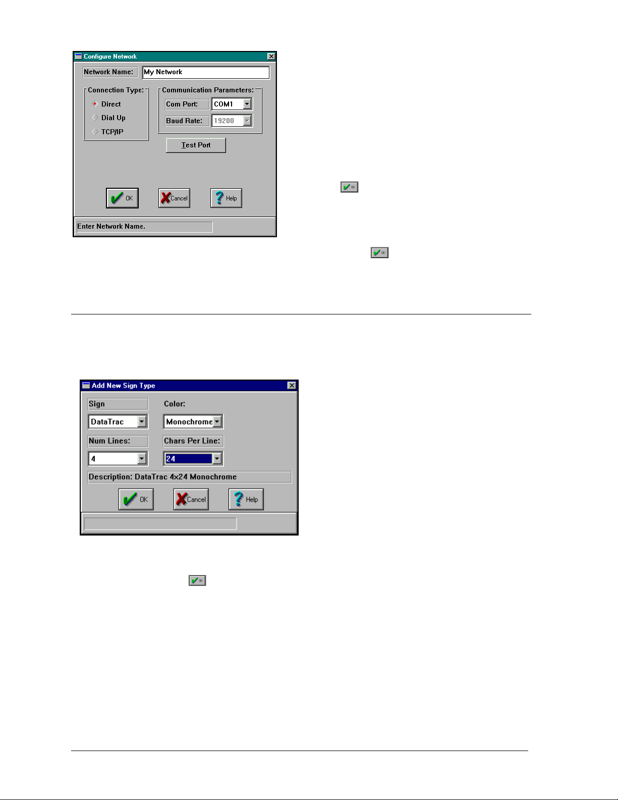
A network named “My Network” is now configured. Click
configuration screen.
3.4 Setting Up a Sign Ty pe
Once the network is setup, the sign can be configured. Before a sign can be setup, the sign type
must be configured. The sign type is a name assigned based upon the sign technology
(DataTrac, InfoNet, Galaxy, SunSpot or Glow Cube) and the sign size.
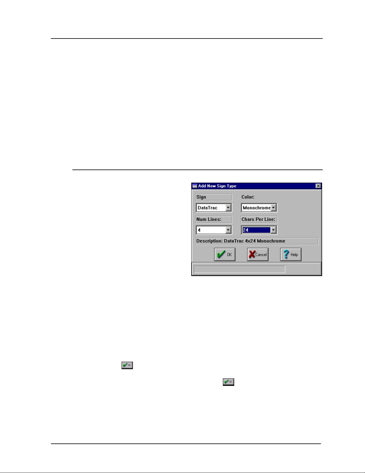
4. Select “4” and “24” from the Num Lines and Chars Per Line boxes, resp ectively, to
select the sign’s size.
5. Click on
to save the sign type. The Edit Sign Types screen will be automatically
activated for the newly configured sign type.
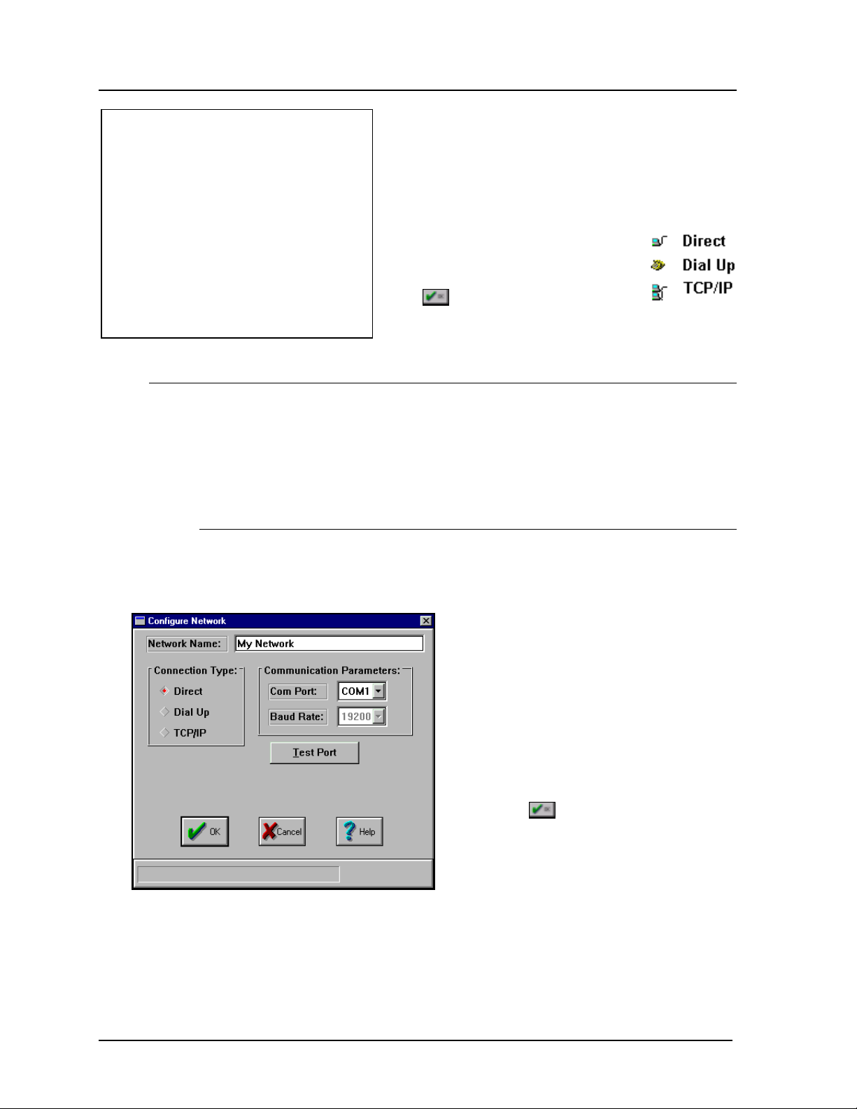
Use the following steps to configure your network.
1. With the mouse click on Direct in the Connection
Type list. This tells the Venus 1500 that the signs
on this network are connected through a serial port
and not via modem or an Ethernet connection.
2. Select the correct serial port from the Com Port list
box.
3. Enter a name for the network in the Network
Name editor. Example: “My Network”
4. Click on
or press <ENTER> to save these
settings.
to return to the main
DataTrac
For a monochrome DataTrac sign with four
lines and 24 characters p er line, the sign type is
“DataTrac 4x24 Monochrome.”
1. To configure a sign type, first click on
SIGN DATABASE] from the Configure
[
Venus 1500 screen.
2. Click on [
ADD TYPE]. Select “DataTrac”
from the Sign list.
3. Choose “Monochrome” from the Color
list.
3-2
Getting Started – Example
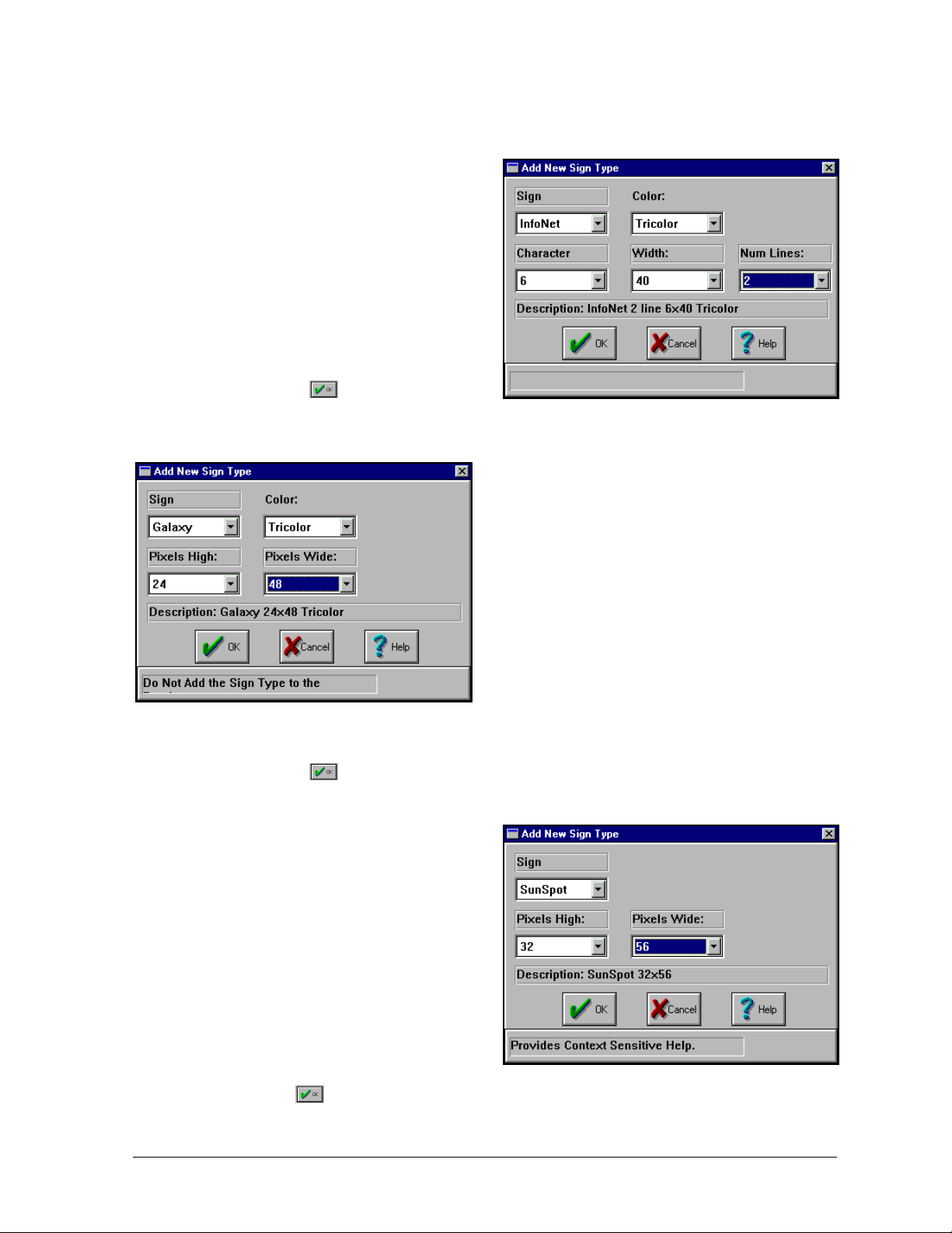
InfoNet
For a tricolor InfoNet sign with a character height of 6 pixels, 40 columns of pixels per line
and two lines of display area, the sign type is “InfoNet 2 line 6x40 Tricolor.”
1. To configure a sign type, first click
SIGN DATABASE] from the
on [
Configure Venus 1500 screen.
2. Click on [
ADD TYPE].
3. Select “InfoNet” from the Sign list.
4. Choose “Tricolor” from the Color
list.
5. Select “6”, “40” and “2” from the
Character, Width and Num
Lines boxes, respectively, to select
the sign’s size.
6. Click on
to save the sign type.
The Edit Sign Types screen will be automatically activated for the newly configured
sign type.
5. Select “24” and “48” from the Pixels High and Pixels Wide boxes, respectively, to
select the sign’s size.
6. Click on
to save the sign type. The Edit Sign Types screen will be automatically
activated for the newly configured sign type.
SunSpot
For a SunSpot sign 32 pixels high by 56
pixels wide, the sign type is “SunSpot
32x56.” (All SunSpot signs are
monochrome.)
1. To configure a sign type, first click
SIGN DATABASE] from the
on [
Configure Venus 1500 screen.
2. Click on [
ADD TYPE].
3. Select “SunSpot” from the Sign list.
4. Select “32” and “56” from the Pixels
High and Pixels Wide boxes, respectively, to select the sign’s size.
5. Click on
to save the sign type. The Edit Sign Types screen will be automatically
activated for the newly configured sign type.
Galaxy
For a tricolor Galaxy sign 24 pixels high by 48
pixels wide, the sign type is “Galaxy 24x48
Tricolor.”
1. To configure a sign type, first click on
SIGN DATABASE] from the Configure
[
Venus 1500 screen.
2. Click on [
ADD TYPE].
3. Select “Galaxy” from the Sign list.
4. Choose “Tricolor” from the Color list.
Getting Started – Example
3-3
3.5 Configuring the Sign Parameters
Before a sign can receive information from the Venus 1500 software, its address must be
identified. The sign address is a number in the range 1 - 240 that identifies a sign. Each sign
must have a unique address. We will assume for the example that the sign is connected to the
PC with an address of one (1).
Once the sign type is configured (refer to Section 3.4), click on [
window will automatically appear, allowing the first sign to be added.
ADD SIGN]. The Edit Sign
1. Enter a name for the sign in the Sign Name
box. For our example we will use “Sign 1.”
2. Enter the sign’s communication address in the
Address box. Refer to the sign’s installation
manual to determine the proper address. We
will assume that the sign has an address of “1.”
3. Click on
to activate the listing of configured
networks. Select “My Network” from the
Network list.
4. Click on
. The new sign’s name should
appear in the Configured Groups and Signs
list.
5. Click on
6. Click on
7. Click on
to return to the Edit Sign Types screen.
to return to the Configure Venus 1500 screen.
to return to the main Venus 1500 window.
We now have configured a network, sign type and sign. The next step is to create a message to
display on the new sign.
3.6 A Basic Message
For the first message we will keep things very simple. Click on [
MESSAGE] from the main
screen or select Message from the Edit menu. The main Edit Message window will appear.
When messages are created, they are stored on the PC’s hard disk. The messages may be
organized into groups called lib raries. Please note that the word DEFAULT is highlighted in
the Libraries list. The user can create other libraries (refer to Section 5.1). For this example,
the message will be stored in this default library.
3-4
Getting Started – Example
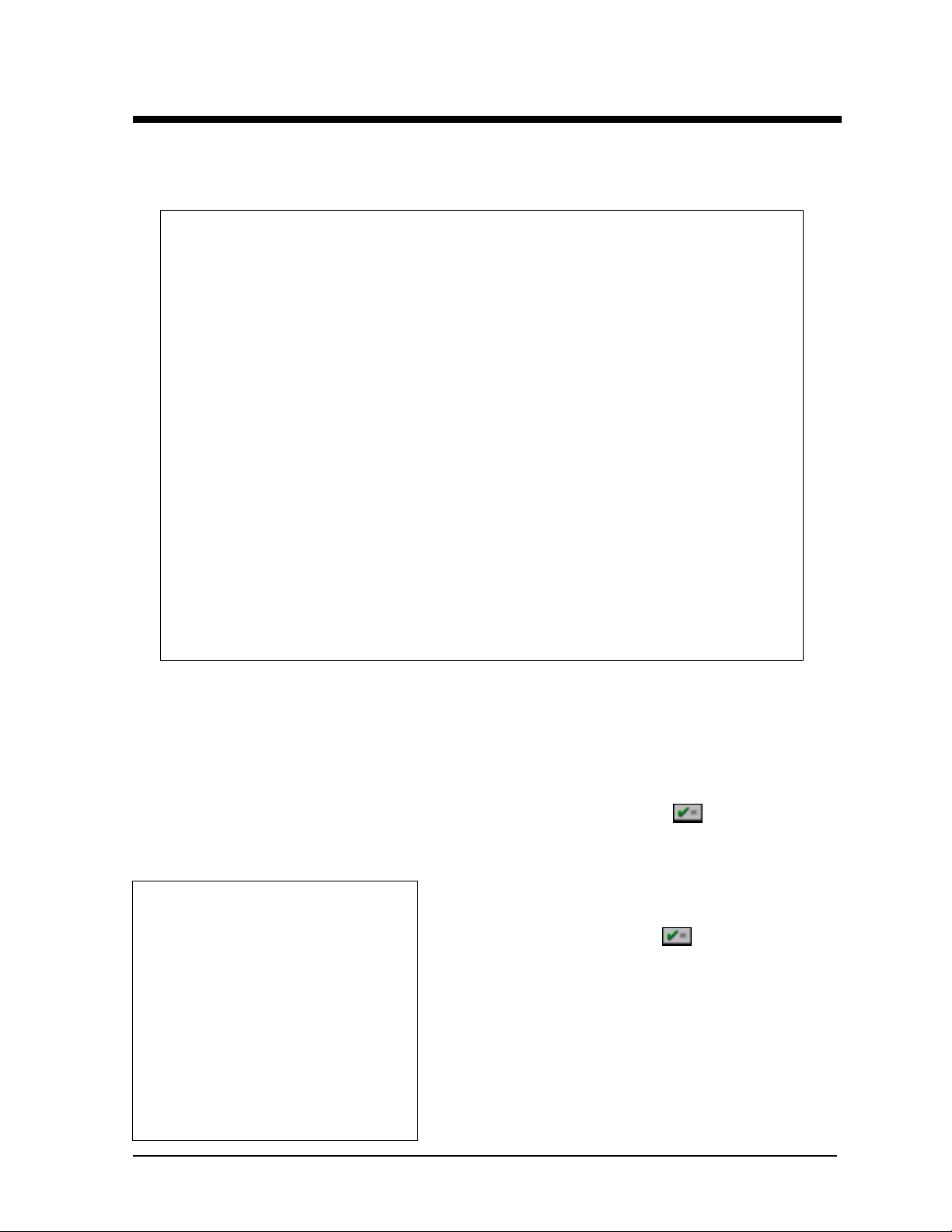
3.6.1 Creating the Message
1. Click once on [
].
TYPE
SIGN
2. Select the sign that you
configured in the
previous two sections.
3. Click on [
MESSAGE
CREATE
].
4. Enter a name for a new
message. Call it
“Message1” for this
example.
5. Click on
. The
message editor will now
load.
The window will show one frame of the message. The size of the editing area will vary
with the sign type. For this test, we will only use one frame.
3.6.2 Text Options
Text Effects
Enter several lines of text into the ed iting area. This is the text that will be
displayed on the sign when we send the message. Place the cursor on the first row
and click on one of the abbreviated “Effect” buttons at the top left side of the
window (IN, SL, SR...). The button chosen will set an effect for that line. Look to
the right of the first row. The letters in the list box should have changed.
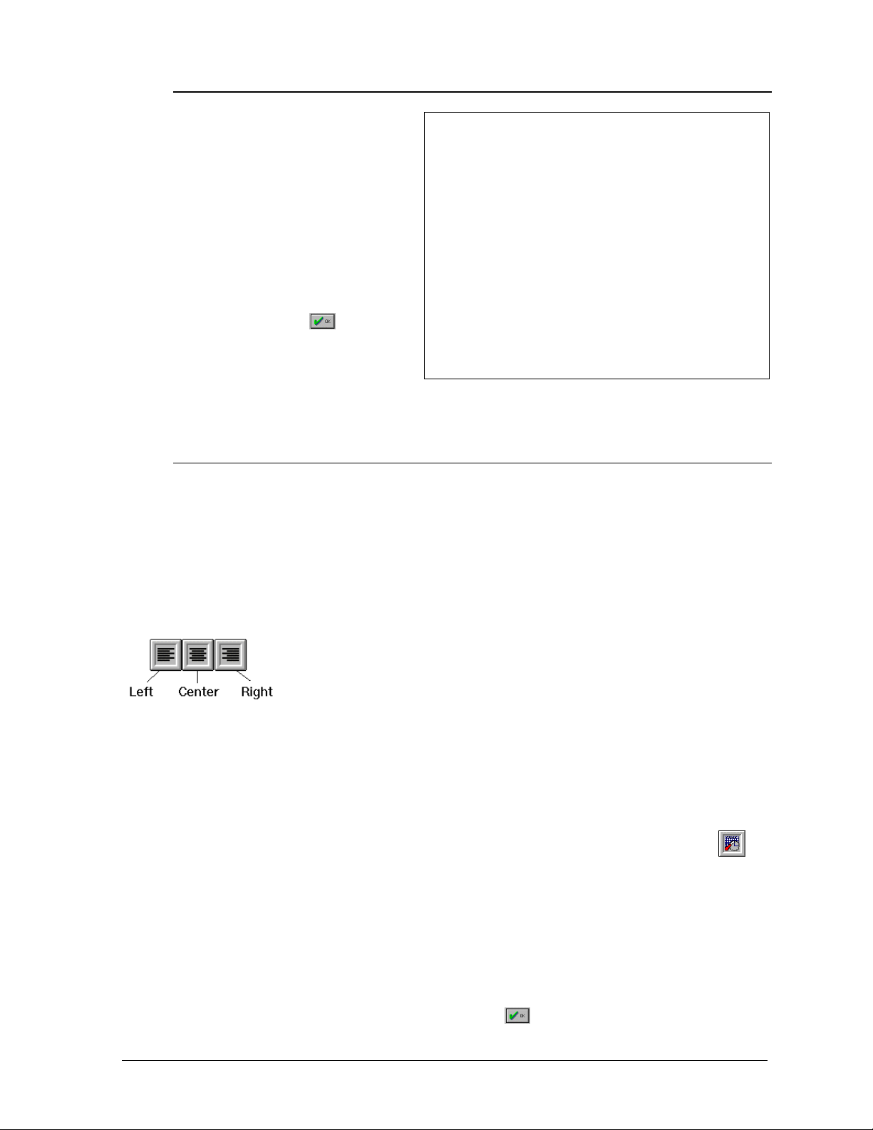
Justification
Place the cursor on another row. Go to the justification buttons located along
the top of the window. Click on the left one. The text should now be flush to
the left of the line.
Flashing
Highlight a word in the th ird line of text then click on the [
FLASH] button. The
highlighted text should now have a gray background to show that it is set to
flashing.
Inserting a Time Field
Place the cursor on a blank line. Click on the date/time/temperature button
the top of the screen. Several examples will show the variety of ways that the date
or time can be set. Choose the last bu tton in the time column (12:00 PM). T he text
will appear on the grid with a blue background. The background is to show that it
is a field, not individual text.
Previewing the Message
Click on the preview arrow at the bottom right of the window. A small window
should appear on the monitor. Congratulations! You are watching a preview of the
message you have just created. Click on
Getting Started – Example
at
to exit the preview window.
3-5

Saving
Now, click on the button at the top of the window that looks like a floppy disk with
an arrow pointing to the right. This button saves the message and activates the
message sender.
3.7 Communications
We are now in the Sign C ommunications screen. This is the screen that is used to communicate
with signs. Note that the Send Message entry in the Commands list is checked. We are now
able to send our test message to the sign.
1. Select the DEFAULT entry from the Libraries list and “Message1” from the Messages
list. This selects our test message from the default library.
2. Now, select “Sign 1” from the Select Signs and Groups list. Our message will be sent to
that sign.
3. Click on [
EXECUTE COMMAND] to download our message to the sign. The message should
now be present in the sign’s memory. Note: The message is not yet running on the sign.
To run the message:
1. Select Run Message from the Commands list.
2. Select the default entry from the Libraries list and “Message1” from the Messages list.
This selects our test message from the default library.
3. Now, select “Sign 1” from the Select Signs and Groups list. Our message will be run on
that sign, because we previously downloaded it there.
4. Click on [
EXECUTE COMMAND] to run the message. The message should now be running
on the sign.
3-6
Getting Started – Example
Section 4: Configuration
Click on Start, then the Programs group, Venus 1500 group and the Venus 1500 icon. The following
screen appears.
Click on [
with the keyboard from the File pull-down menu by pressing <
by just pressing <
CONFIGURE] to configure a sign in the Venus 1500 software. Configure can also be accessed
ALT><F> then selecting Configure or
CTRL><N>.
iIf a password has been configu red, a window will appear asking the user to enter a password once
CONFIGURE] is activated. This password is used to establish a layer of security for the configuration of
[
signs. (To set a password, refer to Section 4.4.1.) Enter the password and click
Once the password is entered correctly, the program will allow the user to continue. To return to the
Main Screen, click on [
CANCEL] or press < ESC>.
The Configure window allows the user to access the Sign
Database, configure a network for Communications and set
some security measures. Click on
return to the main screen.
or press <ENTER>.
or press <ENTER> to
Configuration
4-1
4.1 Communications
4.1.1 Add Network
Click on [
ADD NETWORK] or press <ALT><A> to create a network. A screen will
appear asking for the name of the network and the communication parameters.
There are three (3) connection types that can be used for a sign: direct, dial up and
TCP/IP.
4.1.1.1 Direct Connection
A direct connection indicates a line of communication directly from the
operator’s computer to the sign or network.
Clicking on [
COMMUNICATIONS] or pressing <ALT><C>
configures a network for communicating with signs.
The Configure Communications window allows the user
to add a network, edit an existing network or remove a
network.
The icons next to each name indicate
what type of connection is used.
Click
or press < ENTER> from this
window to return to the main screen.
1. To use this type of connection, click on
Direct in the Connection Type box. A
dot will appear in the box next to the word
to indicate it has been selected.
2. Next it is time to select the
Communication Parameters. Click once
on the down arrow next to the Com Port
box. A listing of valid ports (C OM1
through COM9) will appear.
3. Select the desired serial port for sign
communications. (The default is COM1.)
4. Click on
to save the changes and
return to the Configure Communications
window. [
CANCEL] will abort the
Configure Network screen without saving
any settings.
4-2
Configuration
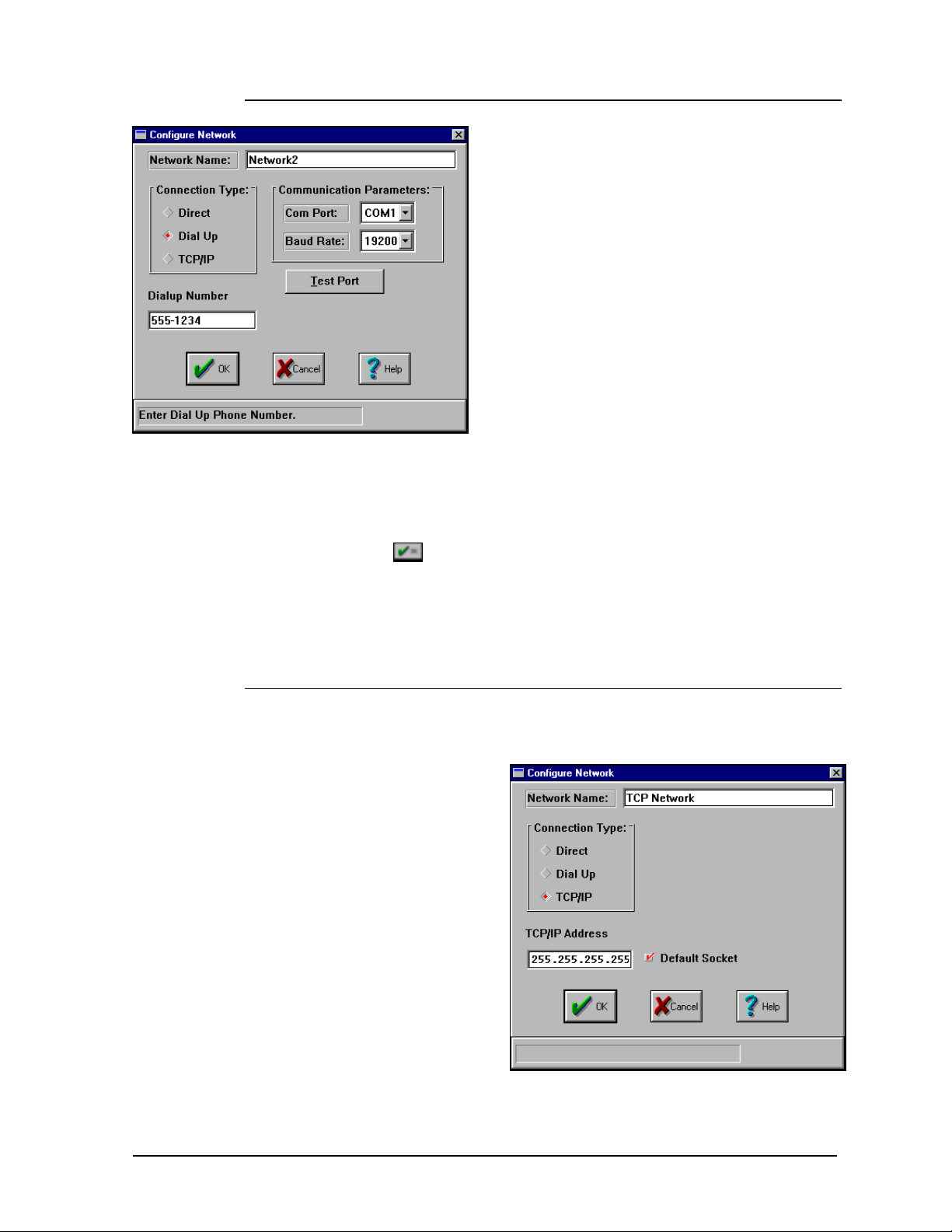
4.1.1.2 Dial Up Connection
A dial up connection uses a modem to communicate
with the sign or network. It is assumed a modem is
already installed and operating properly prior to
selecting a dial-up connection type. For more
information regarding modem installation, consult
the manual accompanying the modem or contact the
modem’s manufacturer.
1. To use this type of connection, click on Dial Up
in the Connection Type box. A dot will appear
in the box next to th e word to indicate it has
been selected.
2. Use the mouse to click once in the Dialup
Number box. Enter the phone number of the
sign. The use of commas and dashes between
numbers are permissible but not necessary.
3. Next it is time to select the Communication Parameters. Click once on
the down arrow next to the Com Port box. A listing of valid ports (COM1
through COM9) will appear.
4. Select the required serial port for sign communications. (The default is
COM1.)
5. Click on
Communications window. [
screen without saving any settings.
*Do not change the Baud Rate from 19,200 for standard sign types. Some
custom applications require other baud rates.
4.1.1.3 TCP/IP Connection
A TCP/IP network uses an Ethernet network and a serial server device to
establish a connection between the Venus 1500 and signs.
The TCP/IP Address is the
address of the serial server
device on the Ethernet
Network. If you are using a
Lantronix MSS1-T, this is
the address that was set on
the device when it was
configured. Refer to
Daktronics manual ED-
9623 for instructions on
configuring MSS1-T and
assigning a static IP
address.
address must match and be
configured on both the
Venus 1500 and the MSS1-T.
The Default Socket should always be checked
MSS1-T.
Configuration
mNote: This
to save the changes and return to the Configure
CANCEL] will abort the Configure Network
q when using the Lantronix
4-3

The Socket Number field is only visible when the Default Socket is not
checked. This field can be used to interface to another serial server device. For
information on the socket number, refer to the serial server’s operation manual
to find which socket is used for a raw data or RS232 connection.
mNote: TCP/IP must be installed and correctly configured for the computer
that the Venus 1500 software is installed on. The TCP/IP protocol must also
be bound to the Ethernet packet/ODI driver. DHCP is not used. The address of
the serial server must be static. Contact your system administrator to obtain a
static IP address and to configur e the computer as needed for your sign
network.
1. To use this type of connection, click on TCP/IP in the Connection Type
box. A dot will appear in the box next to the word to indicate it has been
selected.
2. Use the mouse to click once in the TCP/IP Address box. Enter th e correct
address for the network.
3. If a Lantronix MSS1-T is being used, click on Default Socket, otherwise
enter the socket number in the corresponding box.
4. Click on
Communications window. [
to save the changes and return to the Configure
CANCEL] will abort the Configure Network
screen without saving any settings.
4.1.2 Edit Network
Click on [
EDIT NETWORK] or press <ALT><E> to edit any information entered about
the network.
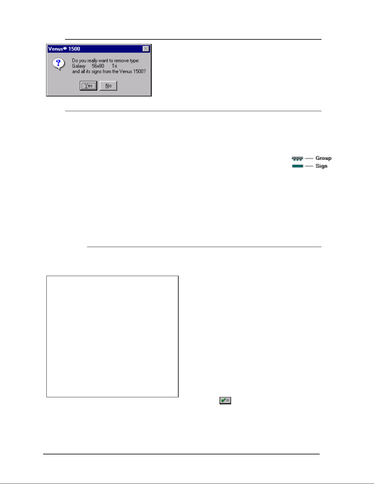
4.1.3 Remove Network
To remove a network, first highlight the desired network and press <
REMOVE NETWORK]. A message will appear asking for a confirmation of the
on [
deletion. Click on [
YES] (or press < ALT><Y>) or [NO] (or press <ALT><N>).
ALT><R> or click
mNote: Performing this action can leave signs unusable.
4-4
Configuration
4.2 Sign Database
Clicking on [
ALT><S> will bring up the Ed it Sign
<
SIGN DATABASE] or pressing
Types window. From this screen, the user
can add and/or delete sign types or edit
signs and groups for sign types.
The number of sign types configured in the
system is virtually unlimited.
4.2.1 Add Type
Note: Confirm your sign size,
technology and color before
configuring the Venus 1500
controller. Incorrect configuration
settings may cause unwanted sign
results.
Clicking on [
pressing <
window for creating new sign
types. Enter the sign technology
(DataTrac, InfoNet, Galaxy,
SunSpot or Glow Cube).
The next series of prompts depend on the type of technology entered. If the sign is a
DataTrac, enter the color (monochrome or tricolor), number of lines in the sign and the
number of characters per line; if the sign is an InfoNet, enter the color, character
height, the width of each line and the number of lines in the sign.
The matrix signs, Galaxy, SunSpot and Glow Cube, require the number of pixels high
and wide to be entered. Galaxy signs may be configured as monochrome or tricolor.
SunSpot and Glow Cube signs are available as monochrome only.
The corresponding description for the configured sign type will automatically appear
above the
Once the sign type has been configured, click on
Sign window (refer to Section 4.2.3) will automatically appear.
ADD TYPE] or
ALT><T> activates a
button.
to save the settings. The Edit
Configuration
4-5
4.2.2 Remove Sign Type
To delete a sign type from the system, highlight the desired
sign type and click on [
REMOVE TYPE] or press <ALT><Y>.
Three windows will appear to confirm the deletion.
4.2.3 Edit Signs
Clicking on [
EDIT SIGNS] or pressing <ALT><E>
will bring up a window for adding a group, adding
a sign, editing a sign or removing a sign or group.
The symbols next to the name
indicate visually whether it is a group
or a sign.
mNote: A network must be created before a sign
can be added to the Venus 1500. Refer to Section
4.1.1.
4.2.3.1 Add Sign
Clicking on [
ADD SIGN] (pressing <ALT><S>) creates a new sign under the
chosen sign type.
To add a sign:
1. Enter a name for the sign. It can be a number
or a brief description of its location.
2. Enter the sign’s network address. (The address
of the sign appears as part of the boot up
initialization information. Refer to the sign’s
maintenance and troubleshooting manual for
more information.)
3. Specify the network the sign is located on.
4. Set the Time Offset if necessary. The offset is
an adjustment from the current time setting on
the PC running the Venus 1500 software. An
offset is advised if you are operating a sign
located in another time zone. The time may be
adjusted by up to
5. Click on
?23 hours.
to save the sign.
If a network is not configured, no selections will be available for network.
Refer to Section 4.1 for instructions on configuring networks.
mNote: A sign cannot be programmed if a network is not configured.
4-6
Configuration
 Loading...