

Daikin RZQG100L8Y1, RZQG140L7Y1, RZQG100L9V1, RZQG125L8Y1, RZQG140L9V1 Service Manual
...
Service Manual
GQI-Eco Series
Heat Pump R-410A 50Hz
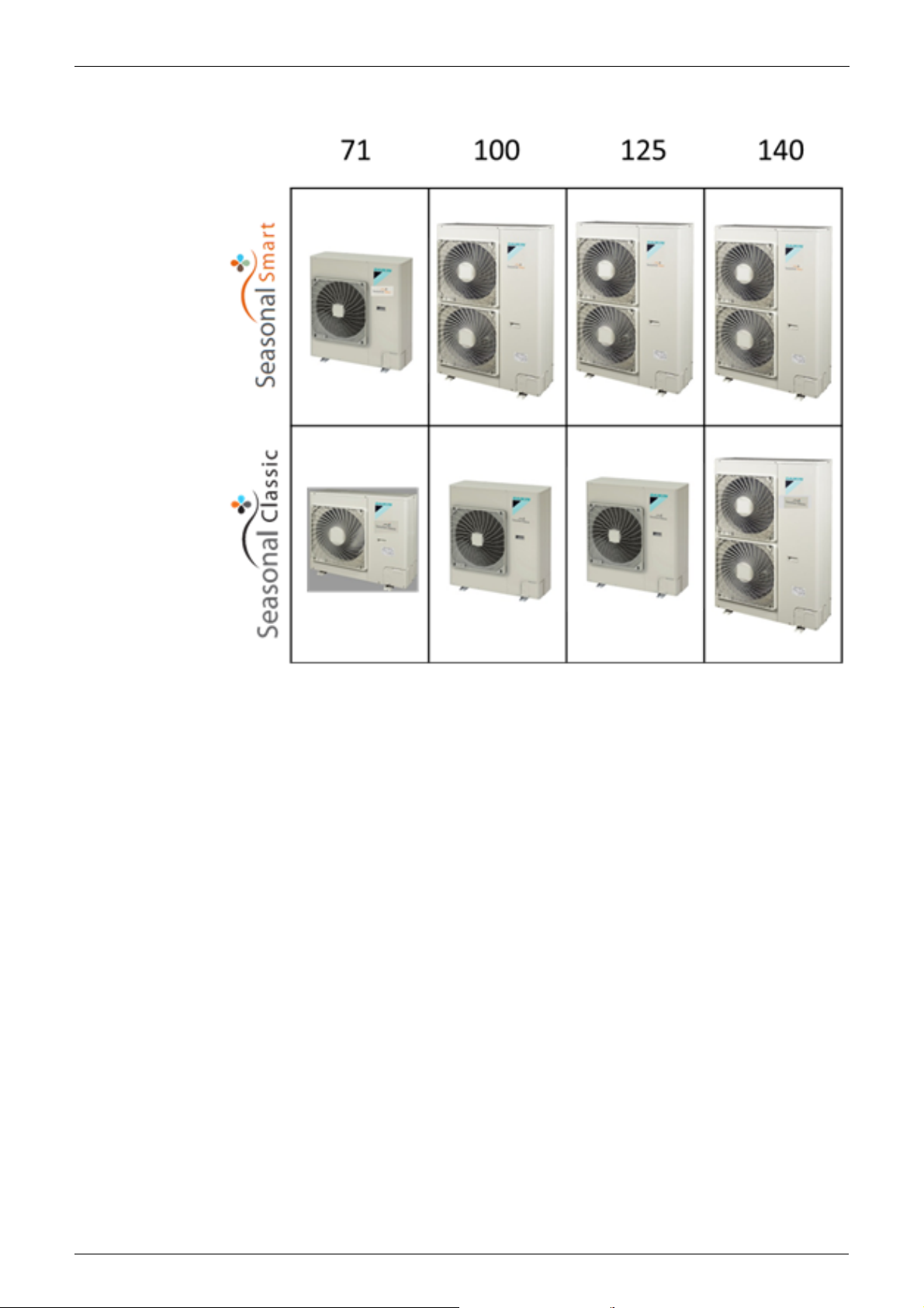
Smart RZQG71~140L9V1
RZQG71~125L9Y1 / RZQG140LY1
Classic RZQSG71L3V1 / RZQSG100~140L9V1
RZQSG100~125L8Y1 / RZQSG140LY1
ESIE15-13C

ESIE15-13C
GQI-Eco Series
Heat Pump
R-410A 50Hz
1. Introduction .............................................................................................v
1.1 Version log ...............................................................................................v
1.2 Safety Cautions ........................................................................................v
1.3 Used Icons ...............................................................................................x
1.4 Preface .................................................................................................... xi
Part 1 - General Information ..........................................................1
1. Model Names of Indoor / Outdoor Units..................................................2
2. Outlook Outdoor Units.............................................................................4
3. Operating range ......................................................................................5
3.1 Smart........................................................................................................5
3.2 Classic......................................................................................................6
3.3 EDP ..........................................................................................................7
Part 2 - Remote Controller ............................................................. 9
1. Wired Remote Controller.......................................................................10
1.1 Applicable Models ..................................................................................10
1.2 Names and Functions ............................................................................10
1.3 MAIN/SUB Setting when Using 2 Remote Controllers ...........................14
1.4 Centralized Control Group No. Setting...................................................15
2. Wireless Remote Controller ..................................................................17
2.1 Applicable Models ..................................................................................17
2.2 Names and Functions ............................................................................17
2.3 MAIN/SUB Setting..................................................................................19
3. Service Mode ........................................................................................20
3.1 BRC1D528 .............................................................................................20
3.2 BRC1E52/53 ..........................................................................................22
4. Inspection Mode....................................................................................25
4.1 BRC1D528 .............................................................................................25
4.2 BRC1E52/53 ..........................................................................................26
Part 3 - Function and Control ....................................................... 27
1. Function of Main Components and Thermistors ...................................28
2. Operation Flow Chart ............................................................................30
2.1 Cooling / Dry Operation..........................................................................30
2.2 Heating Operation ..................................................................................31
3. Function Details ....................................................................................32
3.1 Indoor Unit..............................................................................................32
3.2 Outdoor Unit ...........................................................................................36
Table of Contents i

ESIE15-13C
Part 4 - Field Setting .................................................................... 57
1. Test Operation ......................................................................................58
1.1 Pre-run Checks ......................................................................................58
1.2 Remote Controller Confirmation.............................................................58
1.3 Test Run.................................................................................................59
1.4 Precautions Regarding Test Run ...........................................................59
1.5 Failure Diagnosis at the Moment of First Installation .............................60
2. Field Setting from Remote Controller....................................................61
2.1 Wired Remote Controller........................................................................61
2.2 Wireless Remote Controller ...................................................................66
2.3 Settings Contents and Code No. for Indoor Units ..................................67
2.4 Overview of the Field Setting on the Outdoor Units ...............................73
2.5 Quiet (Low Noise) Operation..................................................................74
2.6 I-Demand Function.................................................................................76
2.7 Setting for Low Humidity Application......................................................77
2.8 Defrost Start Setting ...............................................................................80
2.9 Slow start................................................................................................80
3. Field Setting from Outdoor Unit PCB ....................................................81
3.1 Location of DIP Switch and BS Button...................................................81
3.2 Field Setting for Outdoor Unit.................................................................82
4. Emergency Operation ...........................................................................92
4.1 Forced Operation ...................................................................................92
Part 5 - Service Diagnosis ............................................................ 95
1. Maintenance Inspection ........................................................................97
1.1 Overview ................................................................................................97
2. Symptom-based Troubleshooting .........................................................99
2.1 Overview ................................................................................................99
2.2 Equipment does not Operate ...............................................................100
2.3 Indoor Unit Fan Operates, but Compressor does not Operate ............102
2.4 Cooling / Heating Operation Starts but Stops Immediately ..................104
2.5 After Unit Shuts Down, It cannot be Restarted for a While ..................105
2.6 Equipment Operates but does not Provide Cooling .............................107
2.7 Equipment Operates but does not Provide Heating.............................109
2.8 Equipment Discharges White Mist .......................................................111
2.9 Equipment Produces Loud Noise or Vibration .....................................112
2.10 Equipment Discharges Dust.................................................................113
2.11 Remote Controller LCD Displays "88" ..................................................114
2.12 Swing Flap does not Operate...............................................................115
3. Troubleshooting by LED Indications ...................................................117
3.1 Troubleshooting by LED on the Indoor Unit .........................................117
3.2 Troubleshooting by LED on Outdoor Unit PCB....................................117
4. Troubleshooting by Remote Controller ...............................................118
4.1 Procedure of Self-diagnosis by Remote Controller ..............................118
4.2 Error Codes and Description ................................................................122
4.3 Safety Devices .....................................................................................123
4.4 Indoor Unit PCB Abnormality ...............................................................124
4.5 Drain Water Level System Abnormality................................................125
4.6 Indoor Unit Fan Motor Abnormality ......................................................127
4.7 Capacity Setting Abnormality ...............................................................128
ii Table of Contents

ESIE15-13C
4.8 Transmission Error (between Indoor Unit PCB and Adaptor PCB)......129
4.9 Thermistor Abnormality ........................................................................131
4.10 Humidity Sensor System Abnormality ..................................................132
4.11 Malfunction of Motion Sensor / Floor Temperature Sensor..................133
4.12 Remote Controller Thermistor Abnormality ..........................................138
4.13 Outdoor Unit PCB Abnormality.............................................................139
4.14 High Pressure Abnormality (Detected by the High Pressure Switch)...140
4.15 Actuation of Pressure Sensor...............................................................142
4.16 Compressor Motor Lock .......................................................................144
4.17 Outdoor Unit Fan Motor Abnormality....................................................145
4.18 Electronic Expansion Valve Abnormality..............................................147
4.19 Discharge Pipe Temperature Control...................................................150
4.20 High Pressure Switch System Abnormality ..........................................152
4.21 Low Pressure Switch System Abnormality...........................................153
4.22 Thermistor System Abnormality ...........................................................154
4.23 Outdoor Unit PCB Abnormality.............................................................155
4.24 Radiation Fin Temperature Rise ..........................................................157
4.25 Output Overcurrent Detection ..............................................................159
4.26 Electronic Thermal (Time Lag) .............................................................161
4.27 Stall Prevention (Time Lag)..................................................................163
4.28 Transmission System Abnormality (between Control and Inverter
PCB).....................................................................................................165
4.29 Open Phase or Power Supply Voltage Imbalance ...............................166
4.30 Defective Capacity Setting ...................................................................167
4.31 Refrigerant Shortage (Alert) .................................................................168
4.32 Refrigerant Shortage (Error).................................................................169
4.33 Power Supply Voltage Abnormality ......................................................171
4.34 Transmission Error between Indoor and Outdoor Unit.........................173
4.35 Transmission Error Between Remote Controller and Indoor Unit ........176
4.36 Transmission Error between MAIN Remote Controller and SUB
Remote Controller ................................................................................177
4.37 Field Setting Switch Abnormality..........................................................178
4.38 “UC” Address Duplication of Centralized Controller...............................180
4.39 Transmission Error Between Centralized Controller and Indoor Unit...181
4.40 Transmission Error between Indoor and Outdoor Unit / Piping and
Wiring Mismatch / Refrigerant Shortage ..............................................183
4.41 Check ...................................................................................................185
Part 6 - Appendix ........................................................................197
1. Piping Diagrams..................................................................................198
1.1 RZQG-L9V1 .........................................................................................198
2. Wiring Diagrams..................................................................................199
2.1 Outdoor Unit .........................................................................................199
3. Thermodynamic characteristic of R-410A ...........................................200
4. Removing the switchbox .....................................................................201
Table of Contents iii

ESIE15-13C
iv Table of Contents
ESIE15-13C Introduction
1. Introduction
1.1 Version log
Version history.
Version code Description Date
Version A Preliminary release November 2015
Version B Addition of combination FUQ + RZQSG February 2016
New controller BRC1E53
Fieldsetting on outdoor PCB: setting 2-7 Reduced airflow added
Version C Manual also applicable for RZQG-LY1L April 2017
1.2 Safety Cautions
Cautions and
Warnings
Be sure to read the following safety cautions before conducting repair work.
The caution items are classified into “ Warning” and “ Caution”. The “ Warning”
items are especially important since they can lead to death or serious injury if they are not
followed closely. The “ Caution” items can also lead to serious accidents under some
conditions if they are not followed. Therefore, be sure to observe all the safety caution items
described below.
About the pictograms
This symbol indicates the item for which caution must be exercised.
The pictogram shows the item to which attention must be paid.
This symbol indicates the prohibited action.
The prohibited item or action is shown in the illustration or near the symbol.
This symbol indicates the action that must be taken, or the instruction.
The instruction is shown in the illustration or near the symbol.
After the repair work is complete, be sure to conduct a test operation to ensure that the
equipment operates normally, and explain the cautions for operating the product to the
customer.
1.2.1 Cautions Regarding Safety of Workers
Be sure to disconnect the power cable plug from the plug socket before
disassembling the equipment for repair.
Working on the equipment that is connected to the power supply may cause an
electrical shock.
If it is necessary to supply power to the equipment to conduct the repair or
inspecting the circuits, do not touch any electrically charged sections of the
equipment.
If the refrigerant gas is discharged during the repair work, do not touch the
discharged refrigerant gas.
The refrigerant gas may cause frostbite.
Warning
When disconnecting the suction or discharge pipe of the compressor at the
welded section, evacuate the refrigerant gas completely at a well-ventilated
place first.
If there is a gas remaining inside the compressor, the refrigerant gas or
refrigerating machine oil discharges when the pipe is disconnected, and it may
cause injury.
If the refrigerant gas leaks during the repair work, ventilate the area. The
refrigerant gas may generate toxic gases when it contacts flames.
v

Introduction ESIE15-13C
Warning
The step-up capacitor supplies high-voltage electricity to the electrical
components of the outdoor unit.
Be sure to discharge the capacitor completely before conducting repair work.
A charged capacitor may cause an electrical shock.
Do not start or stop the air conditioner operation by plugging or unplugging the
power cable plug.
Plugging or unplugging the power cable plug to operate the equipment may
cause an electrical shock or fire.
Be sure to wear a safety helmet, gloves, and a safety belt when working at a
high place (more than 2 m). Insufficient safety measures may cause a fall
accident.
In case of R-410A refrigerant models, be sure to use pipes, flare nuts and tools
for the exclusive use of the R-410A refrigerant.
The use of materials for R-22 refrigerant models may cause a serious accident
such as a damage of refrigerant cycle as well as an equipment failure.
Caution
Do not repair the electrical components with wet hands.
Working on the equipment with wet hands may cause an electrical shock.
Do not clean the air conditioner by splashing water.
Washing the unit with water may cause an electrical shock.
Be sure to provide the grounding when repairing the equipment in a humid or
wet place, to avoid electrical shocks.
Be sure to turn off the power switch and unplug the power cable when cleaning
the equipment.
The internal fan rotates at a high speed, and cause injury.
Be sure to conduct repair work with appropriate tools.
The use of inappropriate tools may cause injury.
Be sure to check that the refrigerating cycle section has cooled down enough
before conducting repair work.
Working on the unit when the refrigerating cycle section is hot may cause
burns.
vi
ESIE15-13C Introduction
Caution
Use the welder in a well-ventilated place.
Using the welder in an enclosed room may cause oxygen deficiency.
vii
Introduction ESIE15-13C
1.2.2 Cautions Regarding Safety of Users
Warning
Be sure to use parts listed in the service parts list of the applicable model and
appropriate tools to conduct repair work. Never attempt to modify the
equipment.
The use of inappropriate parts or tools may cause an electrical shock,
excessive heat generation or fire.
If the power cable and lead wires have scratches or deteriorated, be sure to
replace them.
Damaged cable and wires may cause an electrical shock, excessive heat
generation or fire.
Do not use a joined power cable or extension cable, or share the same power
outlet with other electrical appliances, since it may cause an electrical shock,
excessive heat generation or fire.
Be sure to use an exclusive power circuit for the equipment, and follow the local
technical standards related to the electrical equipment, the internal wiring
regulations, and the instruction manual for installation when conducting
electrical work.
Insufficient power circuit capacity and improper electrical work may cause an
electrical shock or fire.
Be sure to use the specified cable for wiring between the indoor and outdoor
units. Make the connections securely and route the cable properly so that there
is no force pulling the cable at the connection terminals.
Improper connections may cause excessive heat generation or fire.
When wiring between the indoor and outdoor units, make sure that the terminal
cover does not lift off or dismount because of the cable.
If the cover is not mounted properly, the terminal connection section may cause
an electrical shock, excessive heat generation or fire.
Do not damage or modify the power cable.
Damaged or modified power cable may cause an electrical shock or fire.
Placing heavy items on the power cable, and heating or pulling the power cable
may damage the cable.
Do not mix air or gas other than the specified refrigerant (R-410A / R-22) in the
refrigerant system.
If air enters the refrigerating system, an excessively high pressure results,
causing equipment damage and injury.
If the refrigerant gas leaks, be sure to locate the leaking point and repair it
before charging the refrigerant. After charging refrigerant, make sure that there
is no refrigerant leak.
If the leaking point cannot be located and the repair work must be stopped, be
sure to perform pump-down and close the service valve, to prevent the
refrigerant gas from leaking into the room. The refrigerant gas itself is
harmless, but it may generate toxic gases when it contacts flames, such as fan
and other heaters, stoves and ranges.
When relocating the equipment, make sure that the new installation site has
sufficient strength to withstand the weight of the equipment.
If the installation site does not have sufficient strength and if the installation
work is not conducted securely, the equipment may fall and cause injury.
viii
ESIE15-13C Introduction
Warning
Check to make sure that the power cable plug is not dirty or loose, then insert
the plug into a power outlet securely.
If the plug has dust or loose connection, it may cause an electrical shock or fire.
Be sure to install the product correctly by using the provided standard
installation frame.
Incorrect use of the installation frame and improper installation may cause the
equipment to fall, resulting in injury.
Be sure to install the product securely in the installation frame mounted on the
window frame.
If the unit is not securely mounted, it may fall and cause injury.
When replacing the coin battery in the remote controller, be sure to disposed
of the old battery to prevent children from swallowing it.
If a child swallows the coin battery, see a doctor immediately.
Caution
Installation of a leakage breaker is necessary in some cases depending on the
conditions of the installation site, to prevent electrical shocks.
For unitary type
only
For unitary type
only
Do not install the equipment in a place where there is a possibility of
combustible gas leaks.
If the combustible gas leaks and remains around the unit, it may cause a fire.
Check to see if the parts and wires are mounted and connected properly, and
if the connections at the soldered or crimped terminals are secure.
Improper installation and connections may cause excessive heat generation,
fire or an electrical shock.
If the installation platform or frame has corroded, replace it.
Corroded installation platform or frame may cause the unit to fall, resulting in
injury.
Check the grounding, and repair it if the equipment is not properly grounded.
Improper grounding may cause an electrical shock.
ix
Introduction ESIE15-13C
Caution
Be sure to measure the insulation resistance after the repair, and make sure
that the resistance is 1 MΩ or higher.
Faulty insulation may cause an electrical shock.
Be sure to check the drainage of the indoor unit after the repair.
Faulty drainage may cause the water to enter the room and wet the furniture
and floor.
Do not tilt the unit when removing it.
The water inside the unit may spill and wet the furniture and floor.
Be sure to install the packing and seal on the installation frame properly.
If the packing and seal are not installed properly, water may enter the room and
wet the furniture and floor.
1.3 Used Icons
Icons are used to attract the attention of the reader to specific information. The meaning of each
icon is described in the table below:
Icon Type of
Note:
Caution
Warning
For unitary type
only
Description
Information
Note A “note” provides information that is not indispensable, but may
nevertheless be valuable to the reader, such as tips and tricks.
Caution A “caution” is used when there is danger that the reader, through
incorrect manipulation, may damage equipment, loose data, get
an unexpected result or has to restart (part of) a procedure.
Warning A “warning” is used when there is danger of personal injury.
Reference A “reference” guides the reader to other places in this binder or
x
in this manual, where he/she will find additional information on a
specific topic.

ESIE15-13C Introduction
1.4 Preface
Thank you for your continued patronage of Daikin products.
This is the new service manual for Daikin's Year 2017 RZQG-L & RZQSG-L series Heat Pump
System.
Daikin offers a wide range of models to respond to building and office air conditioning needs.
We are confident that customers will be able to find the models that best suit their needs.
This service manual contains information regarding the servicing of RZQG-L & RZQSG-L series
R-410A Heat Pump System.
April, 2017
After Sales Service Division
xi

Introduction ESIE15-13C
xii

ESIE15-13C
Part 1
General Information
1. Model Names of Indoor / Outdoor Units..................................................2
2. Outlook Outdoor Units.............................................................................4
3. Operating range ......................................................................................5
3.1 Smart........................................................................................................5
3.2 Classic......................................................................................................6
3.3 EDP ..........................................................................................................7
General Information 1
Model Names of Indoor / Outdoor Units ESIE15-13C
1. Model Names of Indoor / Outdoor Units
Sky-Air
MODEL NAME
(current models)
1 Phase 3 Phase
RZQG71L9V1 RZQG71L8Y1 P 2 P 2 2 2 P 2 P P P P 2
RZQG100L9V1 RZQG100L8Y1 P 32 P 32 32 32 P 32 P P P P 32
RZQG125L9V1 RZQG125L8Y1 P 432 P 432432432 P 432 P P P P 432
RZQG140L9V1 RZQG140L7Y1 2 P43 2 P43 43 43 2 P43 2 P2 2 P43
Sky-Air
MODEL NAME
(current models)
1 Phase 3 Phase
RZQSG71L2/3V1 P 2 P 2 2 2 P 2 P P P P 2
RZQSG100L9V1 RZQSG100L7/
RZQSG125L9V1 RZQSG125L7/
RZQSG140L9V1 RZQSG140L7Y1 2 P43 2 P43 43 43 2 P43 2 P2 2 P43
8Y1
8Y1
3x3 HH
Cassette
FCQHG71FVEB
3x3 Thin Cassette
FCQG35FVEB
FCQG50FVEB
FCQG60FVEB
FCQHG100FVEB
FCQHG125FVEB
FCQHG140FVEB
3x3 HH
Cassette
FCQHG71FVEB
FCQHG100FVEB
FCQHG125FVEB
P 32 P 32 32 32 P 32 P P P P 32
P 432 P 432432432 P 432 P P P P 432
FCQG71FVEB
3x3 Thin Cassette
FCQG35FVEB
FCQG50FVEB
FCQG60FVEB
FCQHG140FVEB
FCQG100FVEB
FCQG125FVEB
FCQG71FVEB
FCQG100FVEB
sette
FFQ35B9V1B
FCQG140FVEB
FCQG125FVEB
FCQG140FVEB
2x2
cas-
FFQ50B9V1B
2x2
cas-
sette
FFQ35B9V1B
2x2
cas-
sette
FFQ60B9V1B
FFQ35C2VEB
FFQ50B9V1B
FFQ60B9V1B
FFQ50C2VEB
2x2
cas-
sette
FFQ35C2VEB
FFQ50C2VEB
Duct (medium
ESP)
FFQ60C2VEB
FBQ35D2VEB
FBQ50D2VEB
FBQ60D2VEB
Duct (medium
FFQ60C2VEB
FBQ35D2VEB
FBQ50D2VEB
FBQ71D2VEB
ESP)
FBQ60D2VEB
FBQ100D2VEB
FBQ71D2VEB
FBQ125D2VEB
FBQ140D2VEB
FBQ100D2VEB
FBQ125D2VEB
Ceil. Susp.
FHQ35CAVEB
FHQ50CAVEB
Ceil. Susp.
FHQ35CAVEB
FBQ140D2VEB
FHQ60CAVEB
FHQ50CAVEB
FHQ71CAVEB
FHQ60CAVEB
FHQ100CAVEB
FHQ71CAVEB
High
4W
Wall
Ceiling
Mount
FAQ71CVEB
FUQ71CVEB
FUQ100CVEB
FHQ140CAVEB
Ceiling
FHQ140CAVEB
4W
FUQ71CVEB
FUQ100CVEB
FUQ125CVEB
Wall
Mount
FAQ71CVEB
FUQ125CVEB
FHQ125CAVEB
FHQ100CAVEB
FHQ125CAVEB
ESP
duct
FAQ100CVEB
High
ESP
duct
FAQ100CVEB
FDQ125B9V3B
FDQ125B9V3B
NEW
Floor
stand
FVQ71CVEB
FVQ100CVEB
NEW
Floor
stand
FVQ71CVEB
FVQ100CVEB
FVQ125CVEB
FVQ140CVEB
FVQ125CVEB
FVQ140CVEB
Slim
duct
FDXS35F2VEB
Slim
duct
FDXS35F2VEB
FDXS50F2VEB
FDXS50F2VEB
FDXS60F2VEB
FDXS60F2VEB
For EDP applications
Sky-Air
MODEL NAME
(current models)
1 Phase 3 phase
RZQG71L9V1 RZQG71L8Y1 P 32 P 32 32 32 P 32 P 32 P P P P
RZQG100L9V1 RZQG100L8Y1 2 P43 2 P43 43 43 2 P43 2 P43 2 2 2 P
RZQG125L9V1 RZQG125L8Y1 2 P43 2 P43 43 43 2 P43 2 P43 2 2 2 P
RZQG140L9V1 RZQG140LY1
Hi
Cassette
FCQHG71FVEB
FCQHG100FVEB
FCQHG125FVEB
Thin Cassette 2x2 cassette Duct (medium ESP) Ceil. Susp.
FBQ35D
FBQ50D
FBQ60D
FBQ71D
FBQ100D
FBQ125D
FBQ140D
FHQ35CAVEB
FCQHG140FVEB
FCQG35FVEB
FCQG50FVEB
FCQG60FVEB
FCQG71FVEB
FFQ35B9V1B
FFQ50B9V1B
FFQ60B9V1B
FFQ35C2VEB
FFQ50C2VEB
FFQ60C2VEB
FBQ35C8VEB
FBQ50C8VEB
FBQ60C8VEB
FBQ71C8VEB
FBQ100C8VEB
FBQ125C8VEB
FCQG100FVEB
FCQG125FVEB
FCQG140FVEB
FBQ140C8VEB
FHQ50CAVEB
FHQ60CAVEB
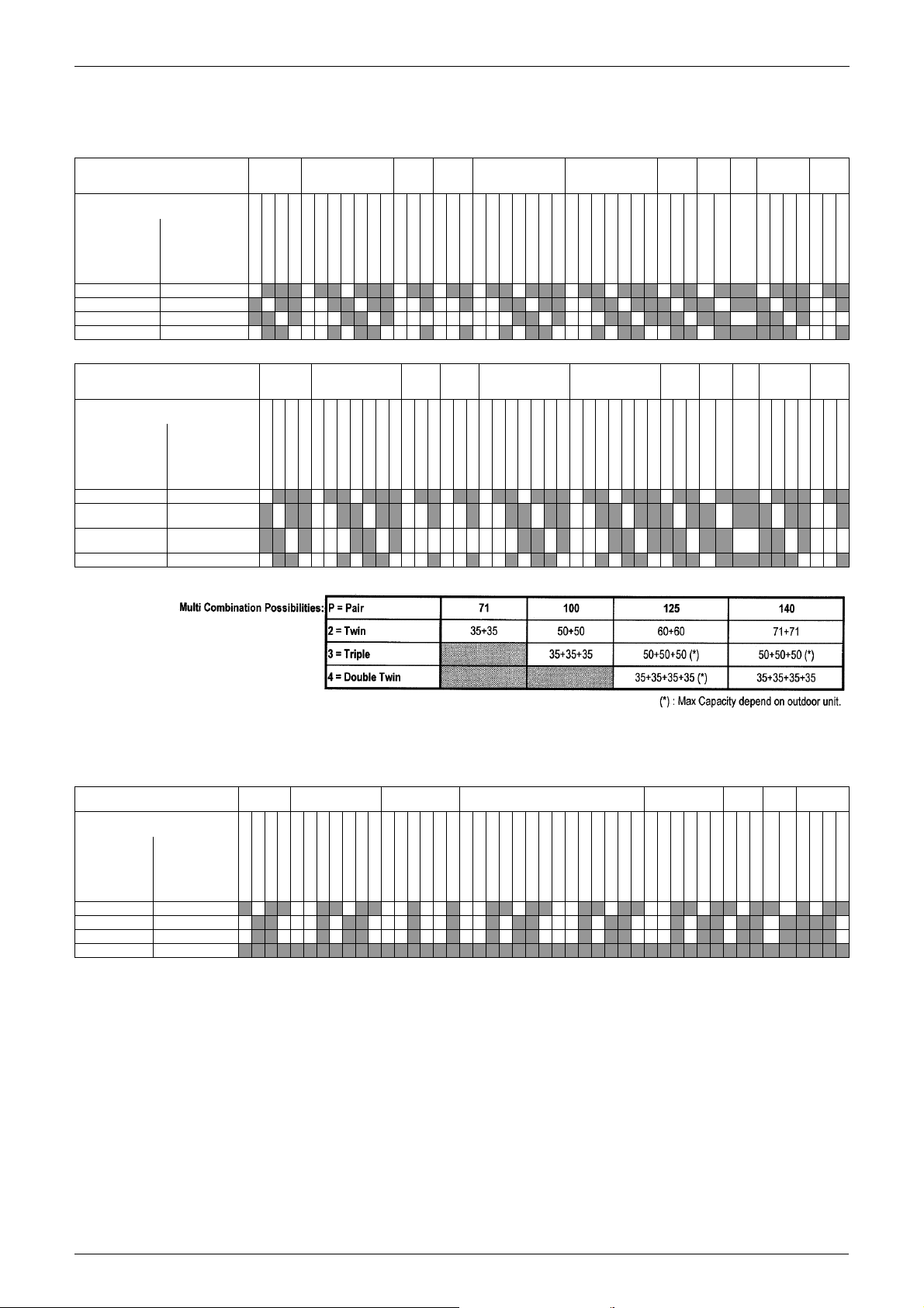
Multi Combination Possibilities:
•P = Pair
• 2 = Twin
• 3 = Triple
• 4 = Double Twin
FHQ71CAVEB
FHQ100CAVEB
Ceiling
FHQ125CAVEB
4W
FUQ71CVEB
Wall
Floor
Mount
Stand
FVQ71CVEB
FAQ71CVEB
FAQ100CVEB
FUQ100CVEB
FUQ125CVEB
FVQ100CVEB
FVQ125CVEB
FVQ140CVEB
2 General Information

ESIE15-13C Model Names of Indoor / Outdoor Units
Note: 1. Individual indoor capacities are not given because the combinations are for simultaneous
operation (= indoor units installed in the same room)
2. When different indoor models are used in combination, designate the remote controller that is
equipped with the most functions as the main unit.
3. See the option list for the selection of the refnet kits that are necessary to install the
combinations:
TWIN: KHRQ22M20TA or KHRQ58T
TRIPLE: KHRQ127H or KHRQ58T
DOUBLE TWIN: KHRQ22M20TA or KHRQ58T
Type of branch piping will depend on the model of indoor unit. Check the option list in the databook for more information.
General Information 3
Outlook Outdoor Units ESIE15-13C
2. Outlook Outdoor Units
4 General Information
ESIE15-13C Operating range
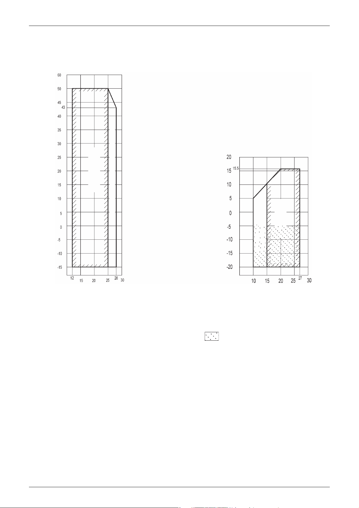
(Cooling)
(Heating)
Operation range
Allowable range of operation (pull-down)
Indoor temp. (°C WB)
Outdoor temp. (°C WB)
Indoor temp. (°C DB)
Outdoor temp. (°C DB)
Operation range
Allowable range of
operation (warming up)
3. Operating range
3.1 Smart
Notes:
1. Depending on operation and installation conditions, the indoor unit can change over to
freeze-up operation (indoor de-icing).
2. To reduce the freeze-up operation (indoor de-icing) frequency it is recommended to install
the outdoor unit in a location not exposed to wind.
3. If the unit has to operate for 5 days in this operation range with 100% humidity, it is
advisable to install the optional bottom plate heater.
General Information 5
Operating range ESIE15-13C
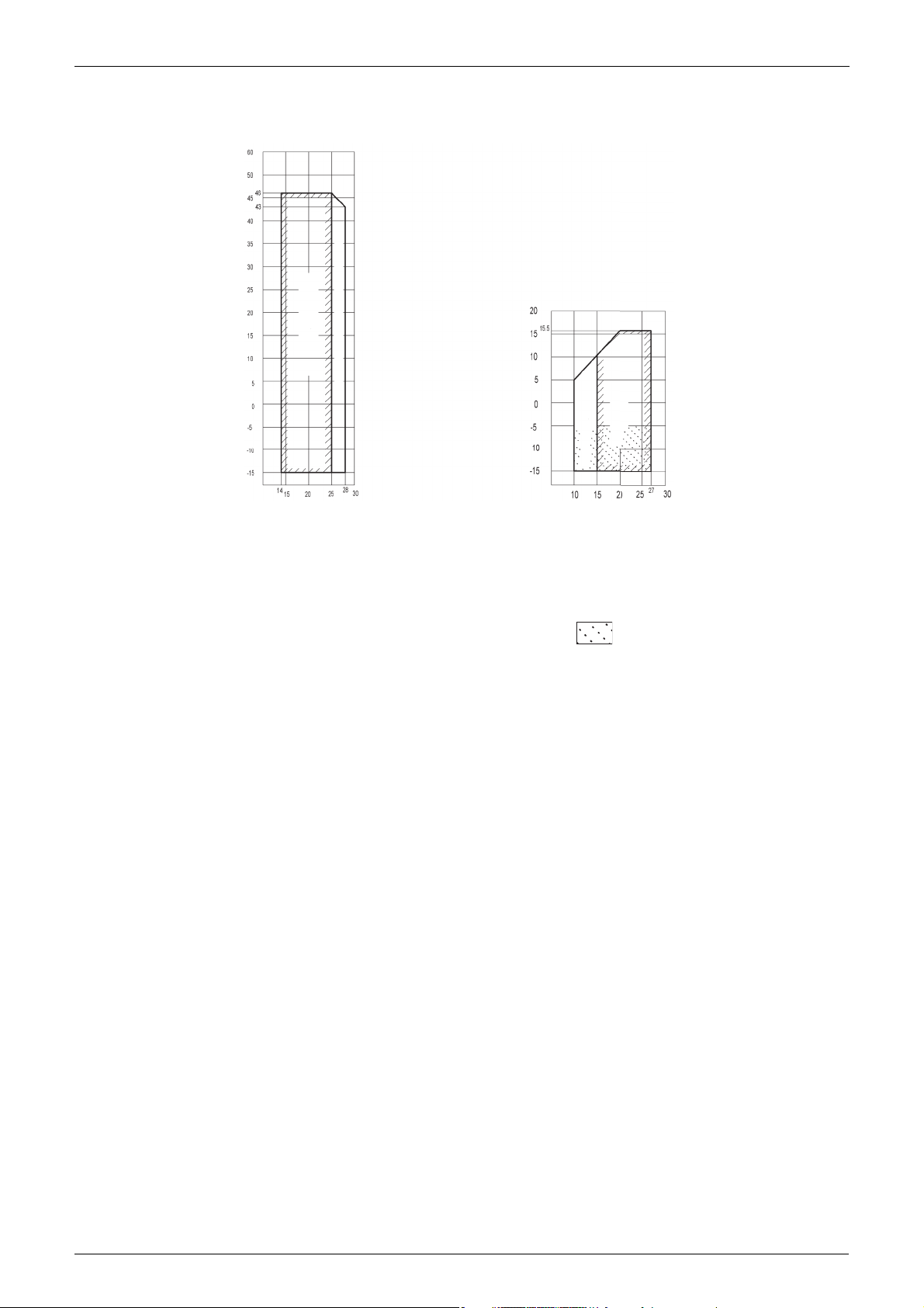
(Cooling)
(Heating)
Operation range
Pull-down operation range
Indoor temp. (°C WB)
Outdoor temp. (°C WB)
Indoor temp. (°C DB)
Outdoor temp. (°C DB)
Operation range
Warm-up operation range
3.2 Classic
Notes:
1. Depending on operation and installation conditions, the outdoor unit can change over to
defrost operation (anti freeze-up).
2. To reduce the defrost operation (anti freeze-up) frequency it is recommended to install the
outdoor unit in a location not exposed to wind.
3. In case of high humidity conditions (>92%) in this operation area, a RZQG model
should be used instead of a RZQSG model. This to avoid freeze-up of the outdoor unit.
6 General Information
ESIE15-13C Operating range
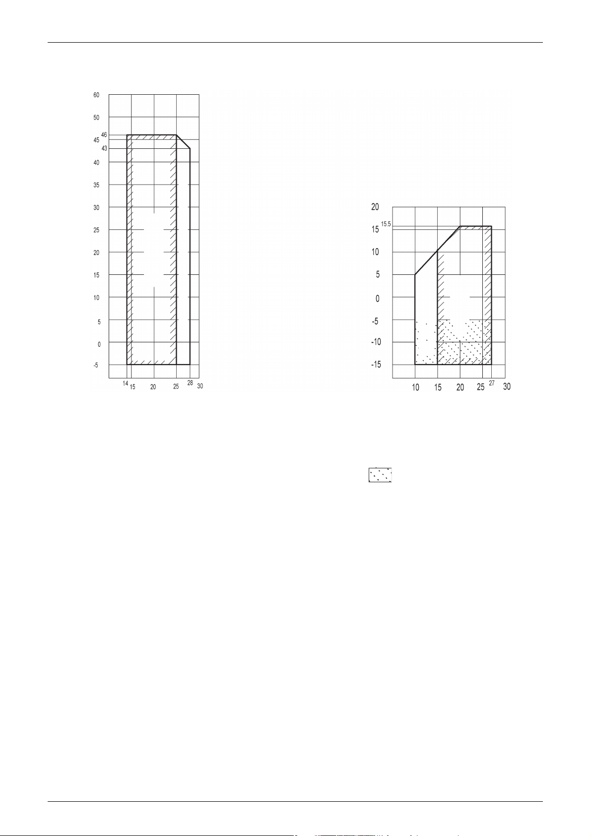
3.3 EDP
(Cooling)
(Heating)
Outdoor temp. (°C DB)
Indoor temp. (°C WB)
Operation range
Notes:
1. Depending on operation and installation conditions, the indoor unit can change over to
2. To reduce the freeze-up operation (indoor de-icing) frequency it is recommended to install
3. In case of high humidity conditions (>92%) in this operation area, a RZQG model
Allowable range of operation (pull-down)
Outdoor temp. (°C WB)
Allowable range of
operation (warming up)
Indoor temp. (°C DB)
Operation range
freeze-up operation (indoor de-icing).
the outdoor unit in a location not exposed to wind.
should be used instead of a RZQSG model. This to avoid freeze-up of the outdoor unit.
General Information 7

Operating range ESIE15-13C
8 General Information

ESIE15-13C
Part 2
Remote Controller
1. Wired Remote Controller.......................................................................10
1.1 Applicable Models ..................................................................................10
1.2 Names and Functions ............................................................................10
1.3 MAIN/SUB Setting when Using 2 Remote Controllers ...........................14
1.4 Centralized Control Group No. Setting...................................................15
2. Wireless Remote Controller ..................................................................17
2.1 Applicable Models ..................................................................................17
2.2 Names and Functions ............................................................................17
2.3 MAIN/SUB Setting..................................................................................19
3. Service Mode ........................................................................................20
3.1 BRC1D528 .............................................................................................20
3.2 BRC1E52/53 ..........................................................................................22
4. Inspection Mode....................................................................................25
4.1 BRC1D528 .............................................................................................25
4.2 BRC1E52/53 ..........................................................................................26
Remote Controller 9
Wired Remote Controller ESIE15-13C
1293
25
22
11
10
37
35
27
26
12
14
17
34
24520 211816 13 15 19
323130
29
28
4
36
33
823 76
1. Wired Remote Controller
1.1 Applicable Models
Model Series FCQHG-F FCQG-F FFQ-C FDXS-F FDBQ-B FBQ-D FDQ-C FDQ-B FAQ-C FHQ-C FUQ-C FNQ-A FVQ-C
Remote
Controller
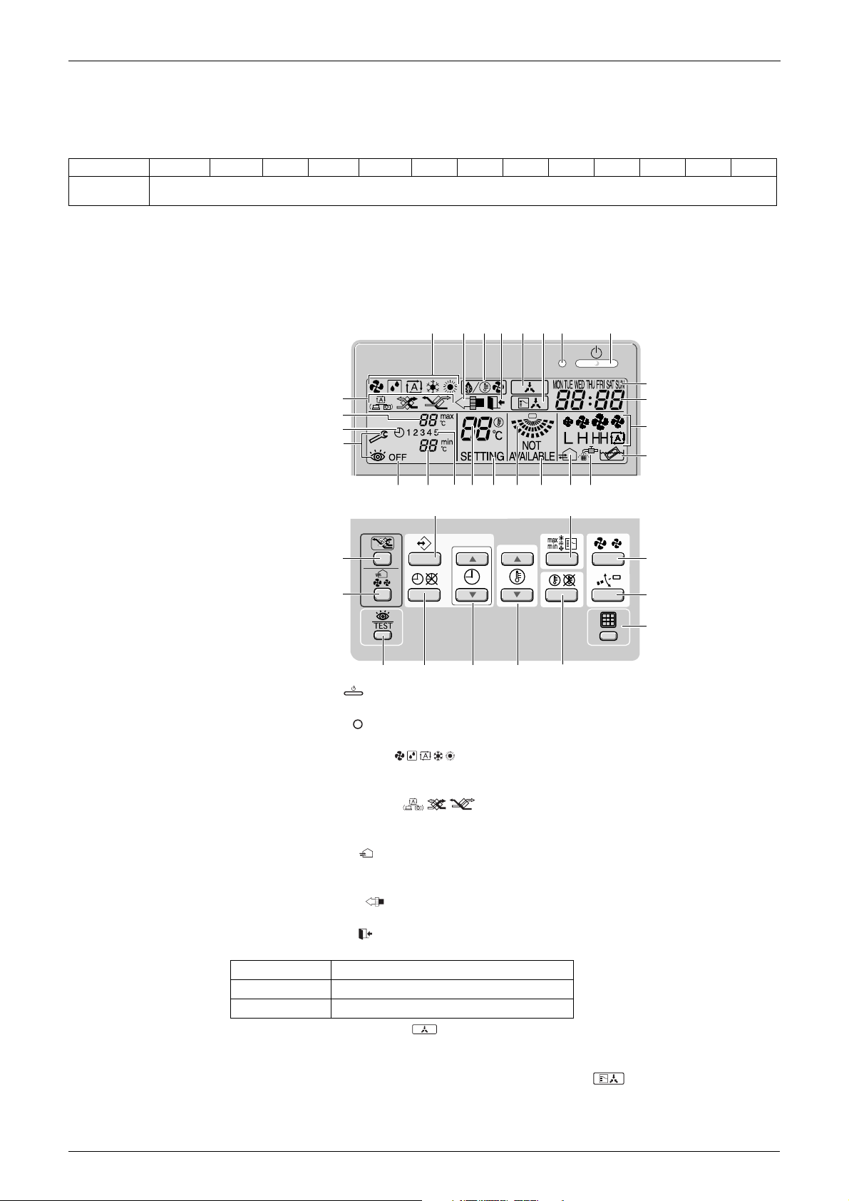
1.2 Names and Functions
1.2.1 BRC1D528
BRC1D52/BRC1E52A/BRC1E52B/BRC1E53
1. ON/OFF BUTTON
Press the ON/OFF button to start or stop the system.
2. OPERATION LAMP
The operation lamp lights up during operation or blinks if an error occurs.
3. OPERATION MODE ICON
These icons indicate the current operation mode (FAN, DRY, AUTOMATIC, COOLING,
HEATING).
4. VENTILATION MODE ICON
These icons indicate the current ventilation mode (HRV only) (AUTOMATIC, HEAT
EXCHANGE, BYPASS).
5. VENTILATION ICON
The ventilation icon appears when the ventilation is adjusted with the ventilation amount
button (HRV only). Simultaneously, the ventilation amount is indicated by the fan speed icon.
6. AIR CLEANING ICON
This icon indicates that the air cleaning unit (option) is operational.
7. LEAVE HOME ICON
The leave home icon shows the status of the leave home function.
ON Leave home is enabled
FLASHING Leave home is active
OFF Leave home is disabled
8. EXTERNAL CONTROL ICON
This icon indicates that another controller with higher priority is controlling or disabling your
installation.
9. CHANGE-OVER UNDER CENTRALISED CONTROL ICON
This icon indicates that the change-over of the installation is under centralised control
assigned to another indoor unit or optional cool/heat selector connected to the outdoor unit
(= Main remote controller).
10 Remote Controller
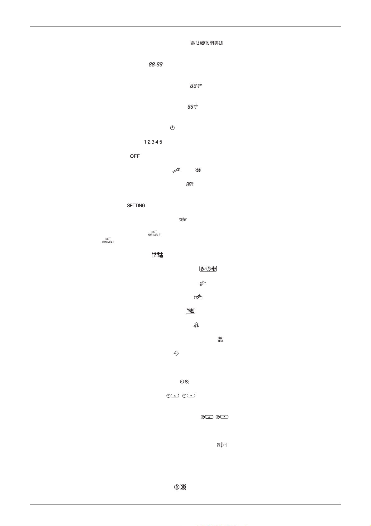
ESIE15-13C Wired Remote Controller
10.DAY OF THE WEEK INDICATOR
The day of the week indicator shows the current week day (or the set day when reading or
programming the schedule timer).
11.CLOCK DISPLAY
The clock display indicates the current time (or the action time when reading or
programming the schedule timer).
12.MAXIMUM SET TEMPERATURE
The maximum set temperature indicates the maximum set temperature when in limit
operation.
13.MINIMUM SET TEMPERATURE
The minimum set temperature indicates the minimum set temperature when in limit
operation.
14.SCHEDULE TIMER ICON
This icon indicates that the schedule timer is enabled.
15.ACTION ICONS
These icons indicate the actions for each day of the schedule timer.
16.OFF ICON
This icon indicates that the OFF action is selected when programming the schedule timer.
17.INSPECTION REQUIRED and
These icons indicate that inspection is required. Consult your installer.
18.SET TEMPERATURE DISPLAY
This indicates the current set temperature of the installation (not shown in LIMIT operation or
in FAN or DRY mode).
19.SETTING
Not used, for service purposes only.
20.AIRFLOW DIRECTION ICON
This icon indicates the airflow direction (only for installations with motorised airflow flaps).
21.NOT AVAILABLE
is displayed whenever a non-installed option is addressed or a function is not
available.
22.FAN SPEED ICON
This icon indicates the set fan speed.
23.DEFROST/HOTSTART MODE ICON
This icon indicates that the defrost/hotstart mode is active.
24.AIR FILTER CLEANING TIME ICON
This icon indicates the air filter must be cleaned. Refer to the manual of the indoor unit.
25.ELEMENT CLEANING TIME ICON
This icon indicates the element must be cleaned (HRV only).
26.VENTILATION MODE BUTTON
The ventilation mode button operates the HRV; refer to the manual for more details.
27.VENTILATION AMOUNT BUTTON
This button sets the ventilation amount; refer to the manual for more details.
28.INSPECTION/TEST OPERATION BUTTON
Not used, for service purposes only.
29.PROGRAMMING BUTTON
This button is a multi-purpose button.
Depending on the previous manipulations of the user, the programming button can have
various functions.
30.SCHEDULE TIMER BUTTON
This button enables or disables the schedule timer.
31.TIME ADJUST BUTTON
These buttons are used to adjust the clock or, when in programming mode, to adjust the
programmed action time. Both buttons have an auto-repeat function.
32.TEMPERATURE ADJUST BUTTONS
These buttons are used to adjust the current setpoint or, when in programming mode, to
adjust the programmed setpoint temperature (step = 1°C). Both buttons are also used to
adjust the day of the week.
33.OPERATION CHANGE/MIN-MAX BUTTON
This button is a multi-purpose button. Depending on the previous manipulations of the user,
it can have following functions:
1 select the operation mode of the installation (FAN, DRY, AUTOMATIC, COOLING,
HEATING)
2 toggle between minimum temperature and maximum temperature when in limit operation
34.SETPOINT/LIMIT BUTTON
This button toggles between setpoint, limit operation or OFF (programming mode only).
Remote Controller 11
Wired Remote Controller ESIE15-13C
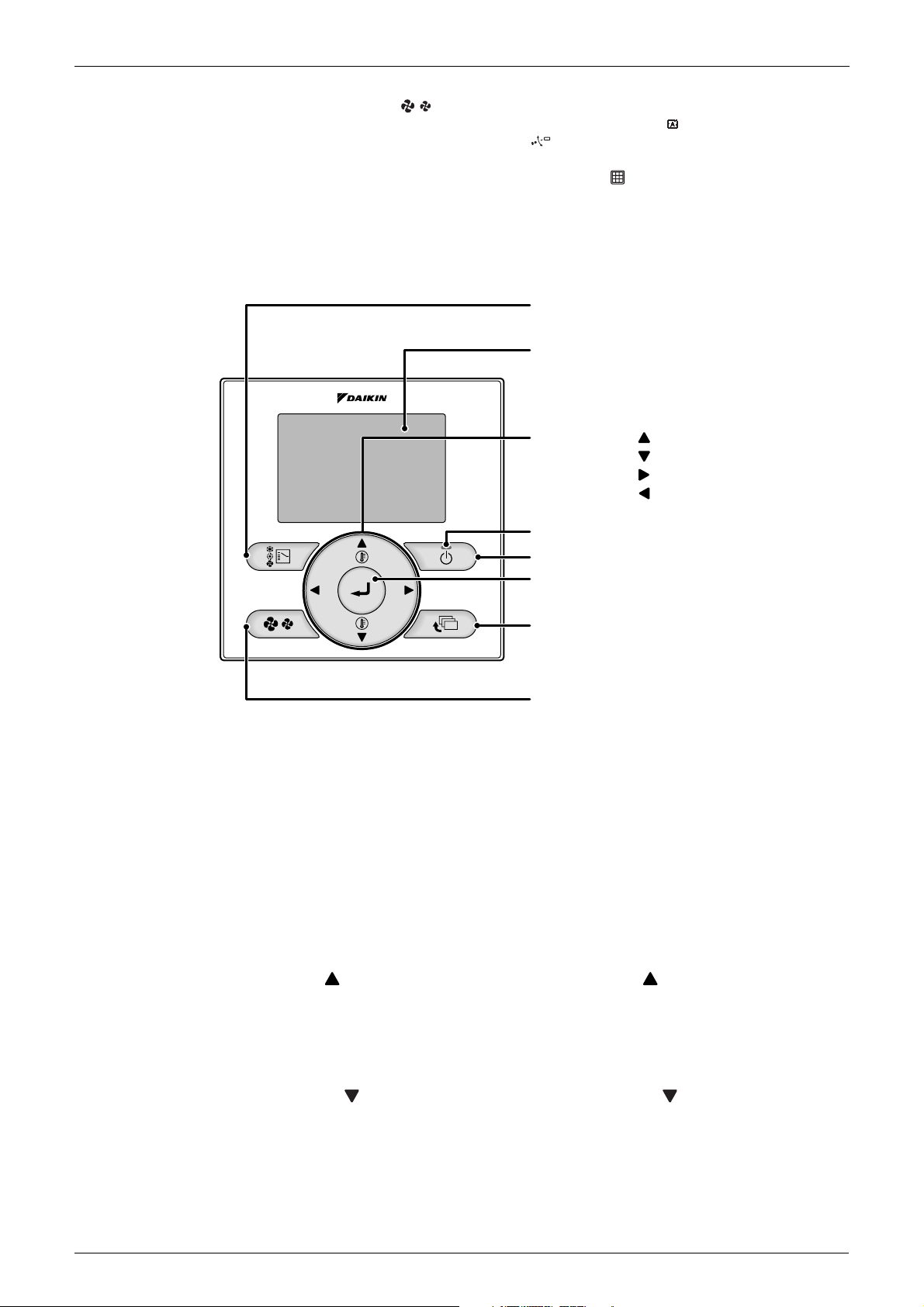
2. Fan speed control button
3. Menu/Enter button
8. On/Off button
10. Cancel button
9. Operation lamp
11. LCD (with backlight)
4. Up button
5. Down button
6. Right button
7. Left button
1. Operation mode
selector button
35.FAN SPEED BUTTON
This button toggles between L (Low), H (High), HH (very High), (Automatic).
36.AIRFLOW DIRECTION ADJUST BUTTON
This button enables to adjust the airflow direction.
37.AIR FILTER CLEANING TIME ICON RESET BUTTON
This button is used to reset the air filter cleaning time icon.
1.2.2 BRC1E52/53
1. Operation mode selector button
Press this button to select the operation mode of your preference.
*Available modes vary with the connecting model.
2. Fan speed control button
Press this button to select the fan speed of your preference.
*Available fan speed vary with the connecting model.
3. Menu/Enter button
Used to indicate the main menu.
Used to enter the setting item selected.
4. Up button (Be sure to press the part with the symbol )
Used to raise the set temperature.
The next items on the upper side will be highlighted.
(The highlighted items will be scrolled continuously when the button is kept pressed.)
Used to change the item selected.
5. Down button (Be sure to press the part with the symbol )
Used to lower the set temperature.
The next items on the lower side will be highlighted.
(The highlighted items will be scrolled continuously when the button is kept pressed.)
Used to change the item selected.
12 Remote Controller
ESIE15-13C Wired Remote Controller
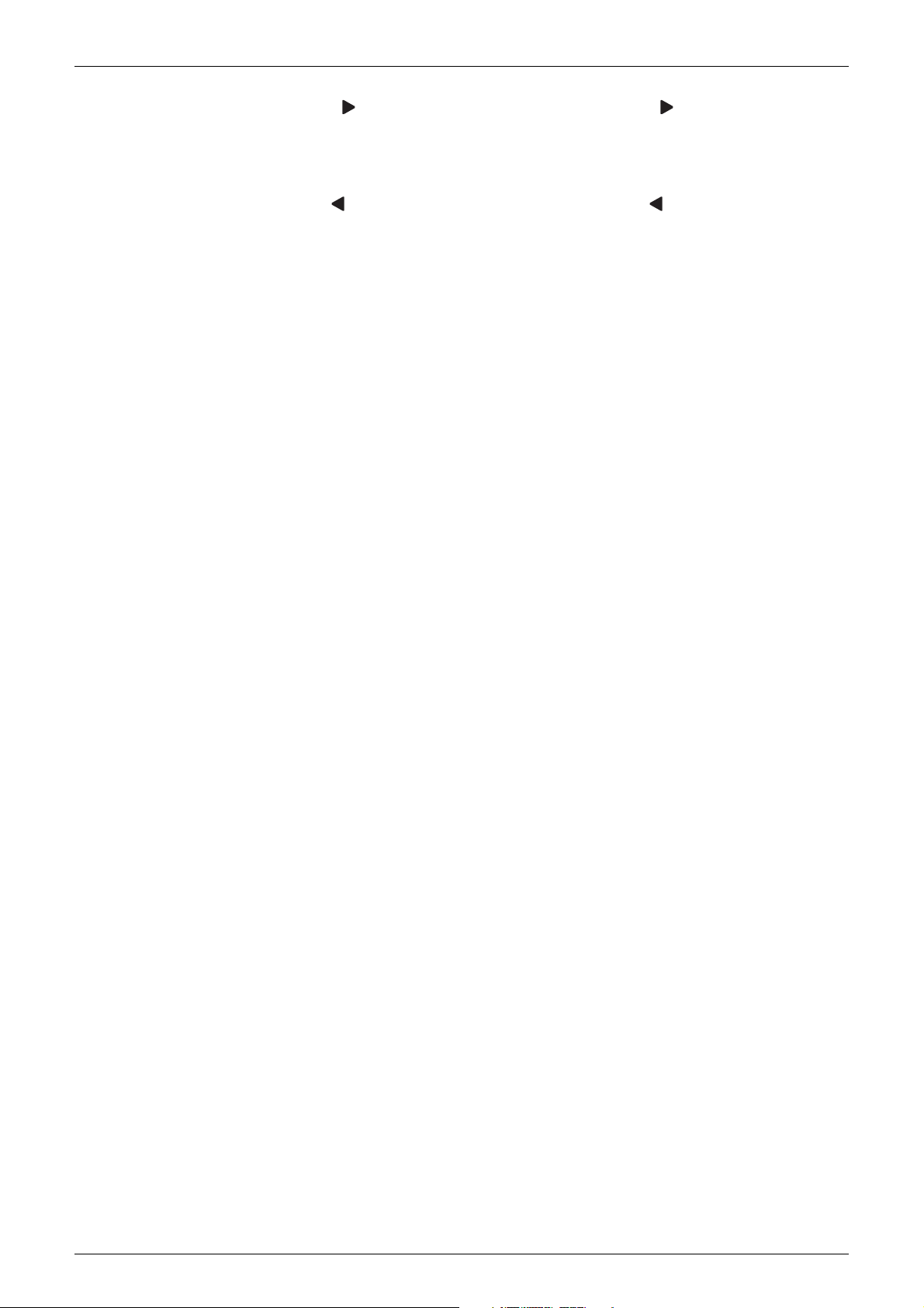
6. Right button (Be sure to press the part with the symbol )
Used to highlight the next items on the right-hand side.
Each screen is scrolled in the right-hand direction.
Home leave settings are enabled with this button kept pressed for at least four seconds.
7. Left button (Be sure to press the part with the symbol )
Used to highlight the next items on the left-hand side.
Each screen is scrolled in the left-hand direction.
Home leave settings are enabled with this button kept pressed for at least four seconds.
8. On/Off button
Press this button and system will start.
Press this button again and system will stop.
9. Operation lamp (Green)
This lamp lights up during operation.
This lamp blinks if an error occurs.
10.Cancel button
Used to return to the previous screen.
11.LCD (with backlight)
The backlight will be light for approximately 30 seconds by pressing any operation button.
Operate buttons excluding the On/Off button while the backlight is lit.
If two remote controllers are used to control a single indoor unit, the backlight of the remote
controller operated earlier than the other one will be lit.
Remote Controller 13
Wired Remote Controller ESIE15-13C
Upper part of the
remote controller
Lower part of the
remote controller
S
M
S
M
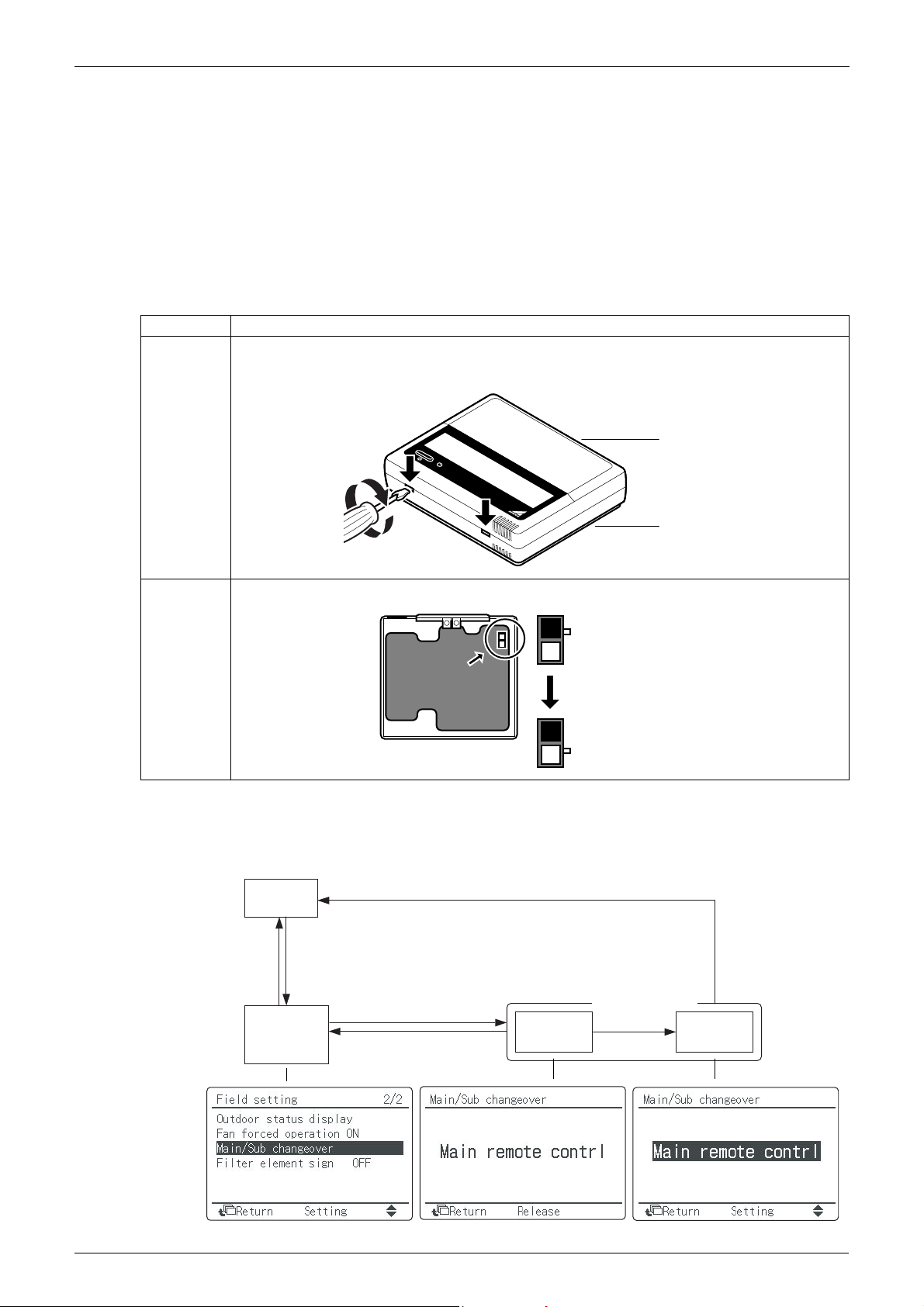
Set the switch to SUB.
The switch is set to
MAI
N (factory setting)
Select "Main/sub changeover"
and press Menu/Enter button.
Field setting
menu is
displayed.
Item 2 is
displayed.
Basic screen
is displayed.
Press and
hold Cancel
button for 4
seconds or
more.
Press
Cancel
button
once.
Press Cancel button.
Item 2 is
displayed.
Press Menu/Enter
button.
Select "Main
remote controller"
or "Sub remote
controller" using
the /
(Up/Down) buttons,
and then press
Menu/Enter button.
1.3 MAIN/SUB Setting when Using 2 Remote Controllers
Situation
The MAIN/SUB setting is necessary when 1 indoor unit is controlled by 2 remote controllers.
When you use 2 remote controllers (control panel and separate remote controller), set one to
MAIN and the other to SUB.
Setting
The remote controllers are factory set to MAIN, so you only have to change 1 remote controller
from MAIN to SUB. To change a remote controller from MAIN to SUB, proceed as follows:
1.3.1 BRC1D528
Step Action
1 Insert a flat-head screwdriver into the recess between the upper and lower part of the remote
controller, as shown in the illustration below. Gently pry off the upper part of the controller, working
from the 2 possible positions.
1.3.2 BRC1E52/53
2 Turn the MAIN/SUB changeover switch on the PCB to “S”.
The designation of the main and sub remote controllers can be swapped. Note that this change
requires turning the power off and then on again.
14 Remote Controller
ESIE15-13C Wired Remote Controller
TEST
TEST
4
1,5
3
2
Group No.
Mode No.
Field setting
mode
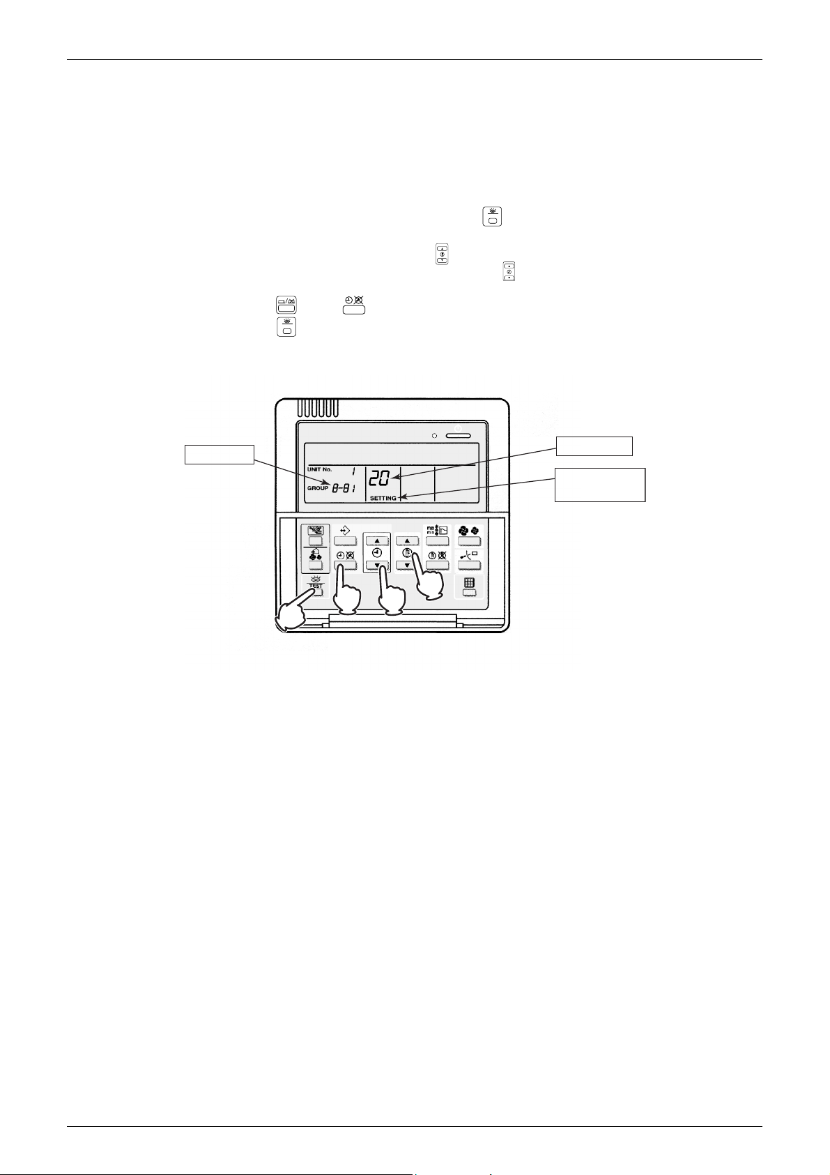
1.4 Centralized Control Group No. Setting
1.4.1 BRC1D528
In order to conduct the central remote control using the central remote controller and the unified
ON/OFF controller, Group No. settings should be made by group using the operating remote
controller.
Make Group No. settings for central remote control using the operating remote controller.
1. During normal mode, press and hold the “ ” button for 4 seconds or more to enter the
"Field Setting Mode".
2. Select the Mode No. “00” with the “ ” button.
3. Select the Group No. for each group with the “ ” button.
(Group numbers increase in the order of 1-00, 1-01, ... 1-15, 2-00, ... 4-15.)
4. Press “ ” or “ ” button to set the selected Group No.
5. Press “ ” button to return to the normal mode.
BRC1D528
NOTICE
Enter the group No. and installation place of the indoor unit into the installation table. Be sure to
keep the installation table with the operation manual for maintenance.
Remote Controller 15
Wired Remote Controller ESIE15-13C
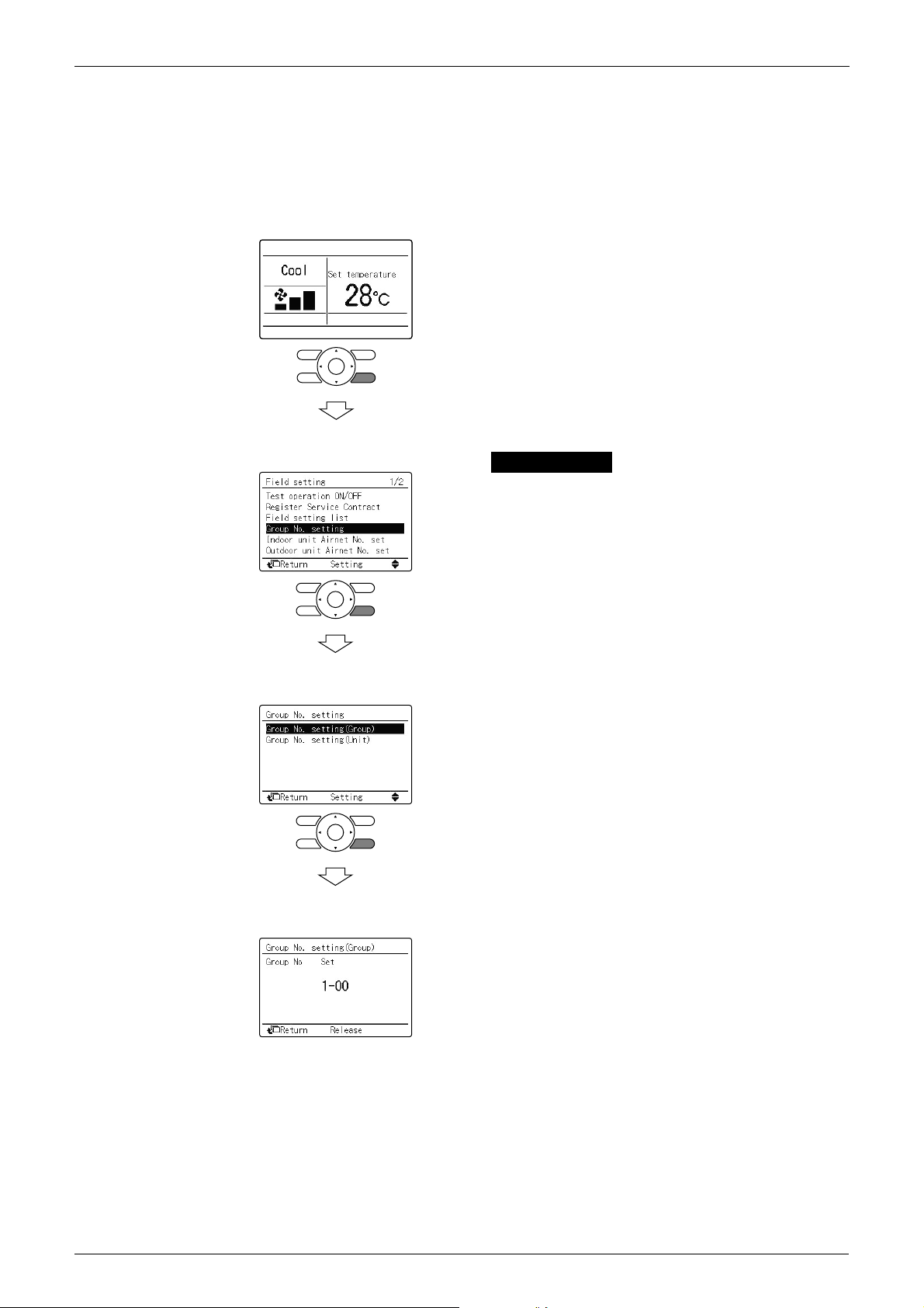
Group No. setting
1.4.2 BRC1E52/53
In order to conduct the centralized remote control using the centralized remote controller and
the unified ON/OFF controller, Group No. settings should be made by group using the operating
remote controller.
Make Group No. settings for centralized remote control using the operating remote controller.
(1) <Basic screen>
Press and hold Cancel button for 4 seconds or more.
Field setting menu is displayed.
(2) <Field setting menu screen>
Select in the field setting menu, and
press Menu/Enter button.
Group No. setting screen is displayed.
(3) <Group No. setting>
Select Group No. setting (Group), and press Menu/Enter
button.
Group No. setting (Group) screen is displayed.
(4) <Group No. setting (Group)>
Select the group No. by using (Up/Down) button.
Press Menu/Enter button.
NOTICE
Enter the group No. and installation place of the indoor unit into the attached installation table.
Be sure to keep the installation table with the operation manual for maintenance.
16 Remote Controller
 Loading...