

Daikin RZQG71L7V1B, RZQG100L7V1B, RZQG125L7V1B, RZQG140L7V1B, RZQG71L7Y1B Service Manual
...
Service Manual
GQI-Eco Series
Heat Pump R-410A 50Hz
Smart RZQG71~140L7V1B
RZQG71~140L7Y1B
Classic RZQSG71~140L7V1B
RZQSG71~140L7Y1B
ESIE12-06

ESIE12-06
i Table of Contents
GQI-Eco Series
Heat Pump
R-410A 50Hz
1. Introduction ............................................................................................iv
1.1 Safety Cautions ....................................................................................... iv
1.2 Used Icons ............................................................................................ viii
1.3 Preface .................................................................................................... ix
Part 1 General Information...........................................................1
1. Model Names of Indoor / Outdoor Units..................................................2
2. Outlook Outdoor Units.............................................................................3
Part 2 Functions ............................................................................5
1. Functions.................................................................................................6
1.1 Indoor Unit................................................................................................6
1.2 Outdoor Unit .............................................................................................6
Part 3 Specifications.....................................................................7
1. Specifications ..........................................................................................8
2. Operation range ....................................................................................75
Part 4 Remote Controller ............................................................79
1. Wired Remote Controller.......................................................................80
1.1 Applicable Models ..................................................................................80
1.2 Names and Functions ............................................................................80
1.3 MAIN/SUB Setting when Using 2 Remote Controllers ...........................84
1.4 Centralized Control Group No. Setting...................................................85
2. Wireless Remote Controller ..................................................................87
2.1 Applicable Models ..................................................................................87
2.2 Names and Functions ............................................................................87
2.3 MAIN/SUB Setting..................................................................................89
3. Service Mode ........................................................................................90
3.1 BRC1D528 .............................................................................................90
4. Inspection Mode....................................................................................92
4.1 BRC1D528 .............................................................................................92
Part 5 Function and Control........................................................93
1. Function of Main Components and Thermistors ...................................94
2. Operation Flow Chart ............................................................................96
2.1 Cooling / Dry Operation..........................................................................96
2.2 Heating Operation ..................................................................................97
3. Function Details ....................................................................................98

ESIE12-06
Table of Contents ii
3.1 Indoor Unit..............................................................................................98
3.2 Outdoor Unit .........................................................................................102
Part 6 Field Setting ...................................................................121
1. Test Operation ....................................................................................122
1.1 Pre-run Checks ....................................................................................122
1.2 Remote Controller Confirmation...........................................................122
1.3 Test Run...............................................................................................123
1.4 Precautions Regarding Test Run .........................................................123
1.5 Failure Diagnosis at the Moment of First Installation ...........................124
2. Field Setting from Remote Controller..................................................125
2.1 Wired Remote Controller......................................................................125
2.2 Wireless Remote Controller .................................................................128
2.3 Settings Contents and Code No. for Indoor Units ................................129
2.4 Overview of the Field Setting on the Outdoor Units .............................134
2.5 Quiet (Low Noise) Operation................................................................135
2.6 I-Demand Function...............................................................................137
2.7 Setting for Low Humidity Application....................................................138
2.8 Defrost Start Setting .............................................................................142
3. Field Setting from Outdoor Unit PCB ..................................................143
3.1 Location of DIP Switch and BS Button.................................................143
3.2 Field Setting for Outdoor Unit...............................................................144
4. Emergency Operation .........................................................................152
4.1 Forced Operation .................................................................................152
Part 7 Service Diagnosis ...........................................................155
1. Maintenance Inspection ......................................................................157
1.1 Overview ..............................................................................................157
2. Symptom-based Troubleshooting .......................................................159
2.1 Overview ..............................................................................................159
2.2 Equipment does not Operate ...............................................................160
2.3 Indoor Unit Fan Operates, but Compressor does not Operate ............162
2.4 Cooling / Heating Operation Starts but Stops Immediately..................164
2.5 After Unit Shuts Down, It cannot be Restarted for a While ..................165
2.6 Equipment Operates but does not Provide Cooling .............................167
2.7 Equipment Operates but does not Provide Heating.............................169
2.8 Equipment Discharges White Mist .......................................................171
2.9 Equipment Produces Loud Noise or Vibration .....................................172
2.10 Equipment Discharges Dust.................................................................173
2.11 Remote Controller LCD Displays "88" ..................................................174
2.12 Swing Flap does not Operate...............................................................175
3. Troubleshooting by LED Indications ...................................................177
3.1 Troubleshooting by LED on the Indoor Unit .........................................177
3.2 Troubleshooting by LED on Outdoor Unit PCB ....................................177
4. Troubleshooting by Remote Controller ...............................................178
4.1 Procedure of Self-diagnosis by Remote Controller ..............................178
4.2 Error Codes and Description ................................................................182
4.3 Safety Devices .....................................................................................183
4.4 Indoor Unit PCB Abnormality ...............................................................184
4.5 Drain Water Level System Abnormality................................................185

ESIE12-06
iii Table of Contents
4.6 Indoor Unit Fan Motor Abnormality ......................................................187
4.7 Capacity Setting Abnormality ...............................................................188
4.8 Transmission Error (between Indoor Unit PCB and Adaptor PCB)......189
4.9 Thermistor Abnormality ........................................................................191
4.10 Humidity Sensor System Abnormality ..................................................192
4.11 Remote Controller Thermistor Abnormality ..........................................193
4.12 Outdoor Unit PCB Abnormality.............................................................194
4.13 High Pressure Abnormality (Detected by the High Pressure
Switch)..................................................................................................195
4.14 Actuation of Pressure Sensor...............................................................199
4.15 Compressor Motor Lock .......................................................................201
4.16 Outdoor Unit Fan Motor Abnormality....................................................202
4.17 Electronic Expansion Valve Abnormality..............................................204
4.18 Discharge Pipe Temperature Control...................................................207
4.19 High Pressure Switch System Abnormality ..........................................209
4.20 Thermistor System Abnormality ...........................................................210
4.21 Outdoor Unit PCB Abnormality.............................................................211
4.22 Radiation Fin Temperature Rise ..........................................................213
4.23 Output Overcurrent Detection ..............................................................215
4.24 Electronic Thermal (Time Lag) .............................................................217
4.25 Stall Prevention (Time Lag)..................................................................219
4.26 Transmission System Abnormality (between Control and
Inverter PCB)........................................................................................221
4.27 Open Phase or Power Supply Voltage Imbalance ...............................222
4.28 Defective Capacity Setting ...................................................................223
4.29 Refrigerant Shortage (Alert) .................................................................224
4.30 Refrigerant Shortage (Error).................................................................225
4.31 Power Supply Voltage Abnormality ......................................................227
4.32 Transmission Error between Indoor and Outdoor Unit.........................229
4.33 Transmission Error Between Remote Controller and Indoor Unit ........232
4.34 Transmission Error between MAIN Remote Controller and
SUB Remote Controller........................................................................233
4.35 Field Setting Switch Abnormality..........................................................234
4.36 “UC” Address Duplication of Centralized Controller...............................236
4.37 Transmission Error Between Centralized Controller and
Indoor Unit............................................................................................237
4.38 Transmission Error between Indoor and Outdoor Unit / Piping
and Wiring Mismatch / Refrigerant Shortage .......................................239
4.39 Check ...................................................................................................241
Part 8 Appendix .........................................................................255
1. Piping Diagrams..................................................................................256
1.1 RZQG71L .............................................................................................256
1.2 RZQG100-140L....................................................................................256
2. Wiring Diagrams..................................................................................257
2.1 Indoor Unit............................................................................................257
2.2 Outdoor Unit .........................................................................................258
3. Precautions for New Refrigerant (R-410A) .........................................259
3.1 Outline ..................................................................................................259
3.2 Refrigerant Cylinders............................................................................261
3.3 Service Tools........................................................................................262
ESIE12-06 Introduction
iv
1. Introduction
1.1 Safety Cautions
Cautions and
Warnings
Be sure to read the following safety cautions before conducting repair work.
The caution items are classified into “ Warning” and “ Caution”. The “ Warning”
items are especially important since they can lead to death or serious injury if they are not
followed closely. The “ Caution” items can also lead to serious accidents under some
conditions if they are not followed. Therefore, be sure to observe all the safety caution items
described below.
About the pictograms
This symbol indicates the item for which caution must be exercised.
The pictogram shows the item to which attention must be paid.
This symbol indicates the prohibited action.
The prohibited item or action is shown in the illustration or near the symbol.
This symbol indicates the action that must be taken, or the instruction.
The instruction is shown in the illustration or near the symbol.
After the repair work is complete, be sure to conduct a test operation to ensure that the
equipment operates normally, and explain the cautions for operating the product to the
customer.
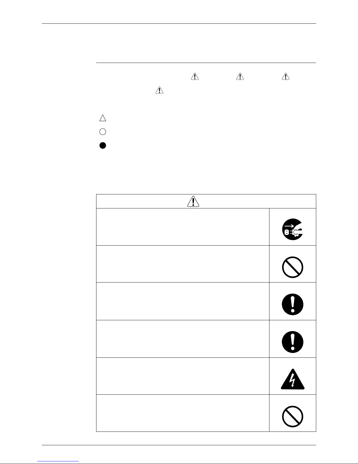
1.1.1 Cautions Regarding Safety of Workers
Warning
Be sure to disconnect the power cable plug from the plug socket before
disassembling the equipment for repair.
Working on the equipment that is connected to the power supply may cause an
electrical shock.
If it is necessary to supply power to the equipment to conduct the repair or
inspecting the circuits, do not touch any electrically charged sections of the
equipment.
If the refrigerant gas is discharged during the repair work, do not touch the
discharged refrigerant gas.
The refrigerant gas may cause frostbite.
When disconnecting the suction or discharge pipe of the compressor at the
welded section, evacuate the refrigerant gas completely at a well-ventilated
place first.
If there is a gas remaining inside the compressor, the refrigerant gas or
refrigerating machine oil discharges when the pipe is disconnected, and it may
cause injury.
If the refrigerant gas leaks during the repair work, ventilate the area. The
refrigerant gas may generate toxic gases when it contacts flames.
The step-up capacitor supplies high-voltage electricity to the electrical
components of the outdoor unit.
Be sure to discharge the capacitor completely before conducting repair work.
A charged capacitor may cause an electrical shock.
Do not start or stop the air conditioner operation by plugging or unplugging the
power cable plug.
Plugging or unplugging the power cable plug to operate the equipment may
cause an electrical shock or fire.

Introduction ESIE12-06
v
Be sure to wear a safety helmet, gloves, and a safety belt when working at a
high place (more than 2 m). Insufficient safety measures may cause a fall
accident.
In case of R-410A refrigerant models, be sure to use pipes, flare nuts and tools
for the exclusive use of the R-410A refrigerant.
The use of materials for R-22 refrigerant models may cause a serious accident
such as a damage of refrigerant cycle as well as an equipment failure.
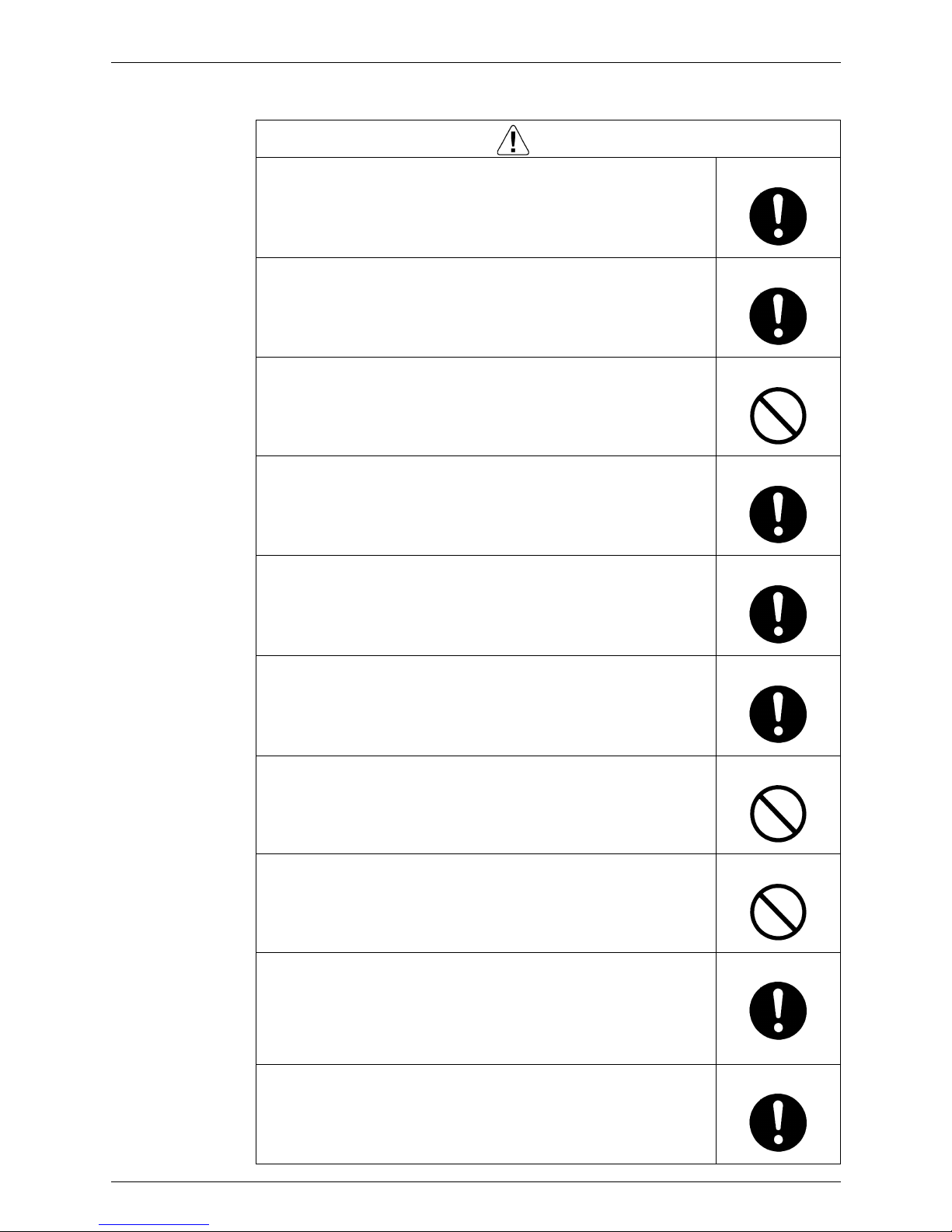
Warning
Caution
Do not repair the electrical components with wet hands.
Working on the equipment with wet hands may cause an electrical shock.
Do not clean the air conditioner by splashing water.
Washing the unit with water may cause an electrical shock.
Be sure to provide the grounding when repairing the equipment in a humid or
wet place, to avoid electrical shocks.
Be sure to turn off the power switch and unplug the power cable when cleaning
the equipment.
The internal fan rotates at a high speed, and cause injury.
Be sure to conduct repair work with appropriate tools.
The use of inappropriate tools may cause injury.
Be sure to check that the refrigerating cycle section has cooled down enough
before conducting repair work.
Working on the unit when the refrigerating cycle section is hot may cause
burns.
Use the welder in a well-ventilated place.
Using the welder in an enclosed room may cause oxygen deficiency.
ESIE12-06 Introduction
vi
1.1.2 Cautions Regarding Safety of Users
Warning
Be sure to use parts listed in the service parts list of the applicable model and
appropriate tools to conduct repair work. Never attempt to modify the
equipment.
The use of inappropriate parts or tools may cause an electrical shock,
excessive heat generation or fire.
If the power cable and lead wires have scratches or deteriorated, be sure to
replace them.
Damaged cable and wires may cause an electrical shock, excessive heat
generation or fire.
Do not use a joined power cable or extension cable, or share the same power
outlet with other electrical appliances, since it may cause an electrical shock,
excessive heat generation or fire.
Be sure to use an exclusive power circuit for the equipment, and follow the local
technical standards related to the electrical equipment, the internal wiring
regulations, and the instruction manual for installation when conducting
electrical work.
Insufficient power circuit capacity and improper electrical work may cause an
electrical shock or fire.
Be sure to use the specified cable for wiring between the indoor and outdoor
units. Make the connections securely and route the cable properly so that there
is no force pulling the cable at the connection terminals.
Improper connections may cause excessive heat generation or fire.
When wiring between the indoor and outdoor units, make sure that the terminal
cover does not lift off or dismount because of the cable.
If the cover is not mounted properly, the terminal connection section may cause
an electrical shock, excessive heat generation or fire.
Do not damage or modify the power cable.
Damaged or modified power cable may cause an electrical shock or fire.
Placing heavy items on the power cable, and heating or pulling the power cable
may damage the cable.
Do not mix air or gas other than the specified refrigerant (R-410A / R-22) in the
refrigerant system.
If air enters the refrigerating system, an excessively high pressure results,
causing equipment damage and injury.
If the refrigerant gas leaks, be sure to locate the leaking point and repair it
before charging the refrigerant. After charging refrigerant, make sure that there
is no refrigerant leak.
If the leaking point cannot be located and the repair work must be stopped, be
sure to perform pump-down and close the service valve, to prevent the
refrigerant gas from leaking into the room. The refrigerant gas itself is
harmless, but it may generate toxic gases when it contacts flames, such as fan
and other heaters, stoves and ranges.
When relocating the equipment, make sure that the new installation site has
sufficient strength to withstand the weight of the equipment.
If the installation site does not have sufficient strength and if the installation
work is not conducted securely, the equipment may fall and cause injury.
Introduction ESIE12-06
vii
Check to make sure that the power cable plug is not dirty or loose, then insert
the plug into a power outlet securely.
If the plug has dust or loose connection, it may cause an electrical shock or fire.
Be sure to install the product correctly by using the provided standard
installation frame.
Incorrect use of the installation frame and improper installation may cause the
equipment to fall, resulting in injury.
For unitary type
only
Be sure to install the product securely in the installation frame mounted on the
window frame.
If the unit is not securely mounted, it may fall and cause injury.
For unitary type
only
When replacing the coin battery in the remote controller, be sure to disposed
of the old battery to prevent children from swallowing it.
If a child swallows the coin battery, see a doctor immediately.
Warning
Caution
Installation of a leakage breaker is necessary in some cases depending on the
conditions of the installation site, to prevent electrical shocks.
Do not install the equipment in a place where there is a possibility of
combustible gas leaks.
If the combustible gas leaks and remains around the unit, it may cause a fire.
Check to see if the parts and wires are mounted and connected properly, and
if the connections at the soldered or crimped terminals are secure.
Improper installation and connections may cause excessive heat generation,
fire or an electrical shock.
If the installation platform or frame has corroded, replace it.
Corroded installation platform or frame may cause the unit to fall, resulting in
injury.
Check the grounding, and repair it if the equipment is not properly grounded.
Improper grounding may cause an electrical shock.
ESIE12-06 Introduction
viii
1.2 Used Icons
Icons are used to attract the attention of the reader to specific information. The meaning of each
icon is described in the table below:
Be sure to measure the insulation resistance after the repair, and make sure
that the resistance is 1 M or higher.
Faulty insulation may cause an electrical shock.
Be sure to check the drainage of the indoor unit after the repair.
Faulty drainage may cause the water to enter the room and wet the furniture
and floor.
Do not tilt the unit when removing it.
The water inside the unit may spill and wet the furniture and floor.
Be sure to install the packing and seal on the installation frame properly.
If the packing and seal are not installed properly, water may enter the room and
wet the furniture and floor.
For unitary type
only
Caution
Icon Type of
Information
Description
Note:
Note A “note” provides information that is not indispensable, but may
nevertheless be valuable to the reader, such as tips and tricks.
Caution
Caution A “caution” is used when there is danger that the reader, through
incorrect manipulation, may damage equipment, loose data, get
an unexpected result or has to restart (part of) a procedure.
Warning
Warning A “warning” is used when there is danger of personal injury.
Reference A “reference” guides the reader to other places in this binder or
in this manual, where he/she will find additional information on a
specific topic.

Introduction ESIE12-06
ix
1.3 Preface
Thank you for your continued patronage of Daikin products.
This is the new service manual for Daikin's Year 2012 RZQG-L & RZQSG-L series Heat Pump
System.
Daikin offers a wide range of models to respond to building and office air conditioning needs.
We are confident that customers will be able to find the models that best suit their needs.
This service manual contains information regarding the servicing of RZQG-L & RZQSG-L series
R-410A Heat Pump System.
September, 2012
After Sales Service Division

ESIE12-06
General Information 1
Part 1
General Information
1. Model Names of Indoor / Outdoor Units..................................................2
2. Outlook Outdoor Units.............................................................................3

Model Names of Indoor / Outdoor Units ESIE12-06
2 General Information
1. Model Names of Indoor / Outdoor Units
For EDP applications
Multi Combination Possibilities:
•P = Pair
• 2 = Twin
• 3 = Triple
• 4 = Double Twin
Note: 1. Individual indoor capacities are not given because the combinations are for simultaneous
operation (= indoor units installed in the same room)
2. When different indoor models are used in combination, designate the remote controller that is
equipped with the most functions as the main unit.
3. See the option list for the selection of the refnet kits that are necessary to install the
combinations:
TWIN: KHRQ22M20TA or KHRQ58T
TRIPLE: KHRQI27H or KHRQ58H
DOUBLE TWIN: KHRQ22M20TA or KHRQ58T
ESIE12-06 Outlook Outdoor Units
General Information 3
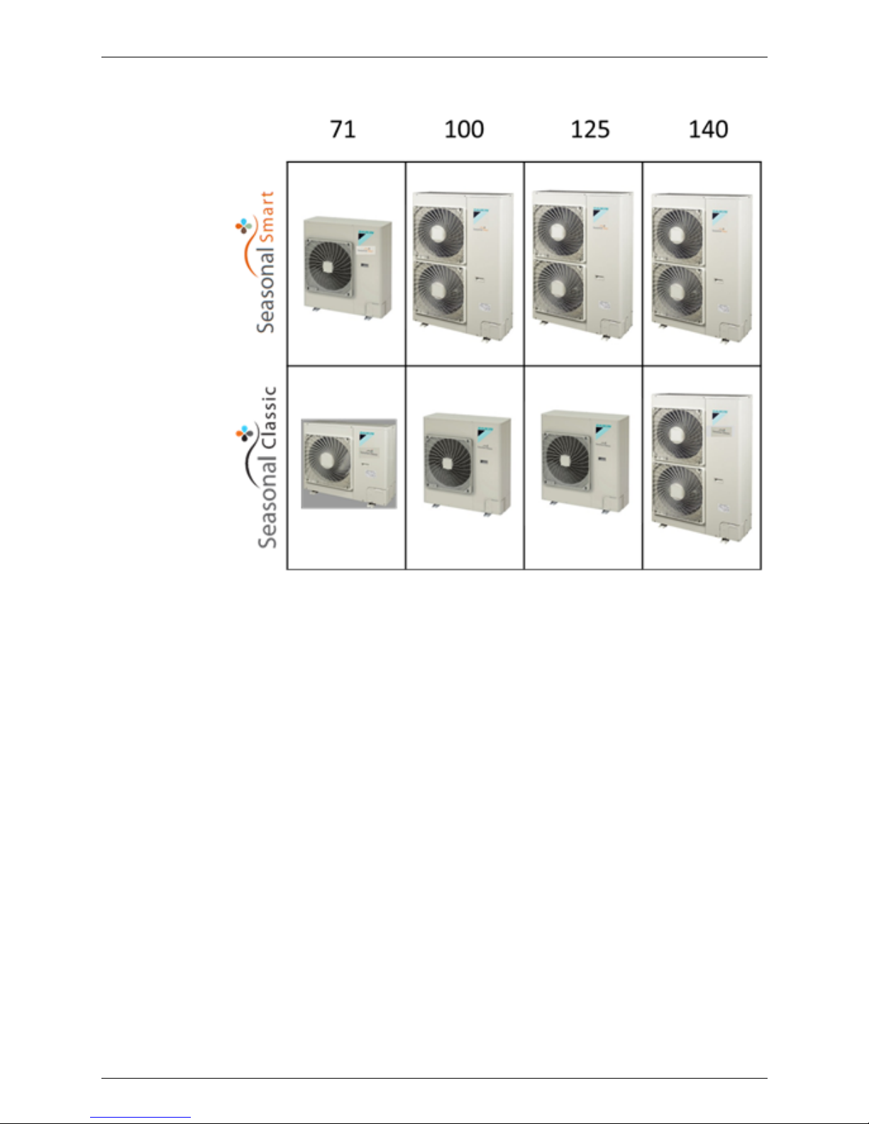
2. Outlook Outdoor Units

Outlook Outdoor Units ESIE12-06
4 General Information

ESIE12-06
Functions 5
Part 2
Functions
1. Functions.................................................................................................5
1.1 Indoor Unit................................................................................................5
1.2 Outdoor Unit .............................................................................................5
Functions ESIE12-06
6 Functions
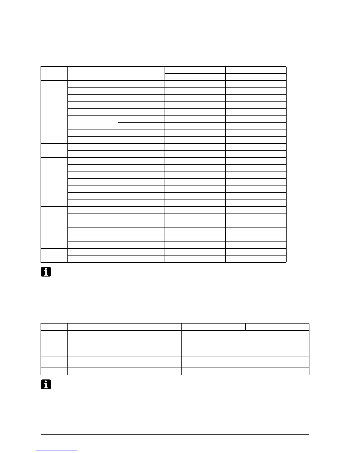
1. Functions
1.1 Indoor Unit
Note:
: Functions exist.
— : No functions
*1 : FHQG71C Installable on max. 3.5m high ceiling
FHQG100~140C Installable on max. 4.3m high ceiling
1.2 Outdoor Unit
Note:
: Functions exist.
— : No functions
Items Features
FCQG-E FHQG-C
Heat Pump Heat Pump
Control Auto swing
Swing pattern selection
Switchable fan speed
Program “Dry”
High ceiling application (*1)
Two selectable
thermo. sensors
Wired type
Wireless type —
Hot start
Timer selector
Mould
prevention
Mould resistant treatment for filter
Mould-proofing drain pan
Work &
servicing
Drain water lift-up mechanism
Pre-charged for up to 30 m
Long-life filter
Filter sign
Ceiling soiling prevention —
Emergency operation
Self-diagnosis function
Control
features
Auto-restart
Auto cooling/heating change-over
Control by 2 remote controllers
Control by 1 remote controller
External command control
Centralized remote control
Option Interlock control
Fresh air intake kit —
Items Functions RZQG71L RZQG100/125/140L
Control Inverter Control
(For Comfortable Air Conditioning)
Night Time Quiet Operation Function for Cooling
EDP Room Applicable
Work &
Servicing
Low Gas Pressure Detection
Others PE Fin for Outdoor Unit

ESIE12-06
Specifications 7
Part 3
Specifications
1. Specifications ..........................................................................................8
2. Operation range ....................................................................................75
Specifications ESIE12-06
8 Specifications
1. Specifications
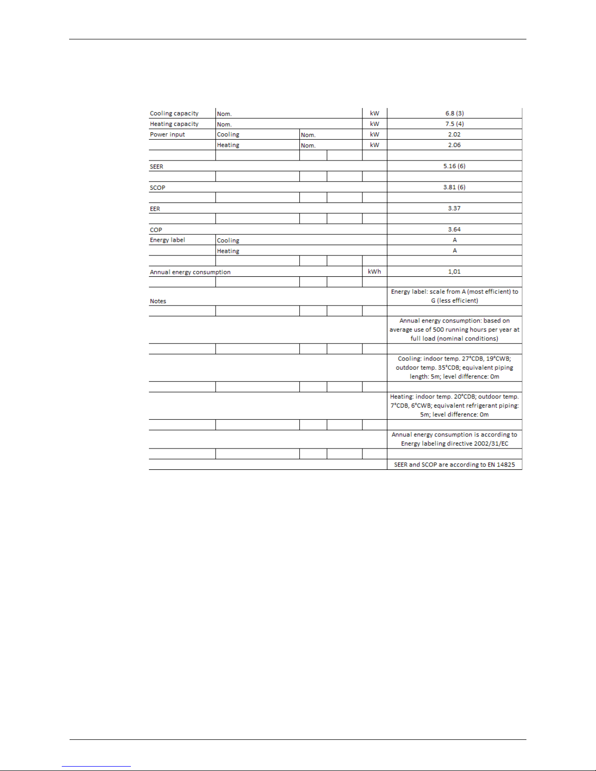
RZQG71V
FVQ71CVEB / RZQG71L7V1B

ESIE12-06 Specifications
Specifications 9
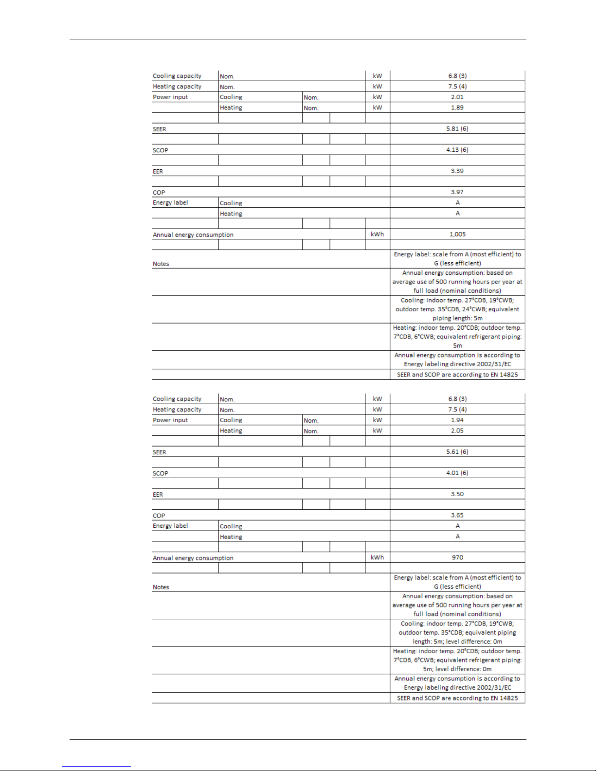
FUQ71BWV1B / RZQG71L7V1B
FUQ71BVV1B / RZQG71L7V1B

Specifications ESIE12-06
10 Specifications
FHQG71CVEB / RZQG71L7V1B
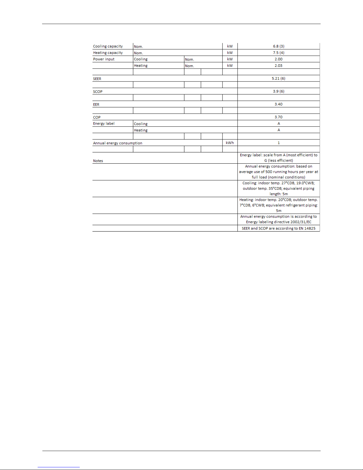
FCQHG71FVEB / RZQG71L7V1B
ESIE12-06 Specifications
Specifications 11
FCQG71FVEB / RZQG71L7V1B
FBQ71C8VEB / RZQG71L7V1B
Specifications ESIE12-06
12 Specifications
FAQ71CVEB / RZQG71L7V1B
ESIE12-06 Specifications
Specifications 13
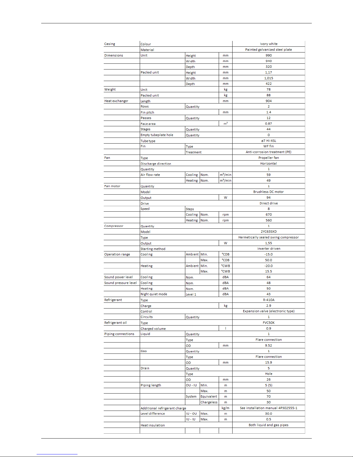
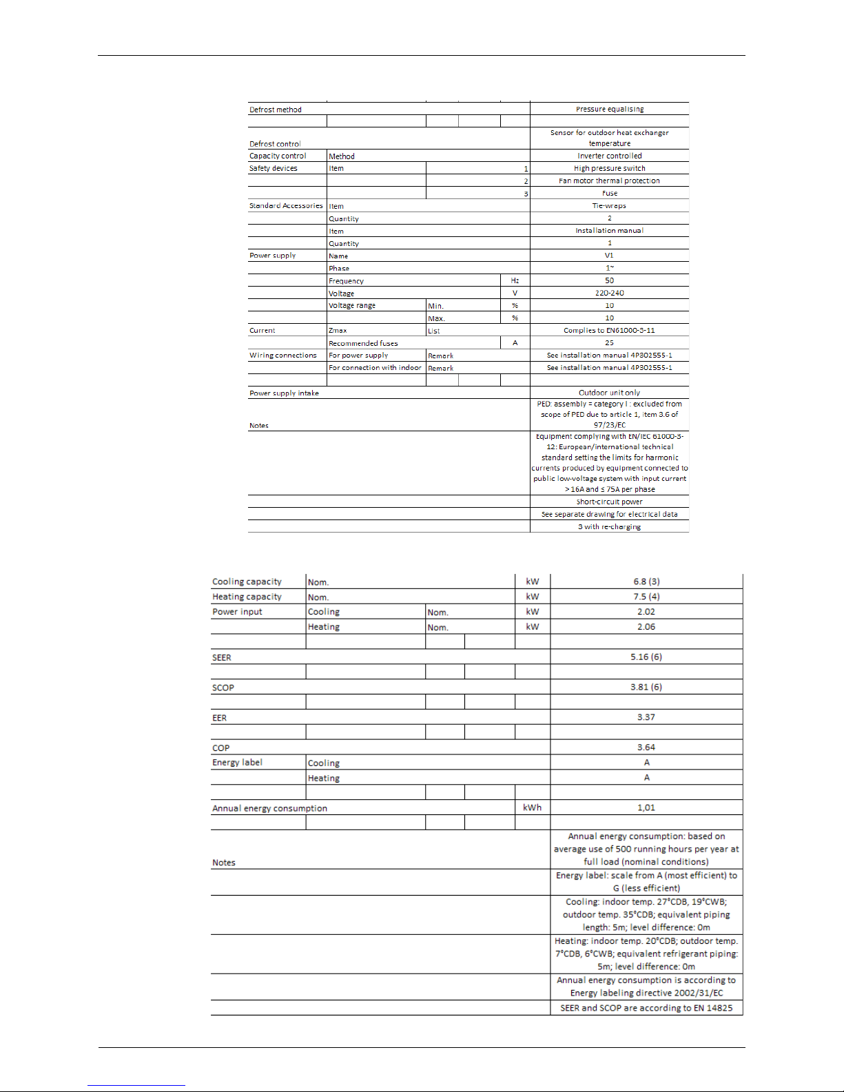
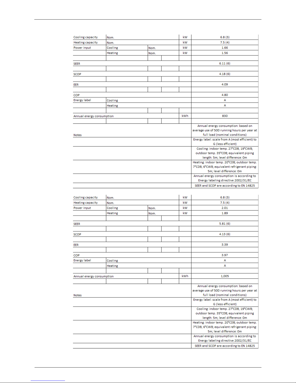
RZQG71L7V1B
Specifications ESIE12-06
14 Specifications
RZQG71Y
FVQ71CVEB / RZQG71L7Y1B

ESIE12-06 Specifications
Specifications 15
FUQ71BWV1B / RZQG71L7Y1B
FHQG71CVEB / RZQG71L7Y1B
Specifications ESIE12-06
16 Specifications
FCQHG71FVEB / RZQG71L7Y1B
FCQG71FVEB / RZQG71L7Y1B

ESIE12-06 Specifications
Specifications 17
FBQ71C8VEB / RZQG71L7Y1B
FAQ71CVEB / RZQG71L7Y1B
Specifications ESIE12-06
18 Specifications
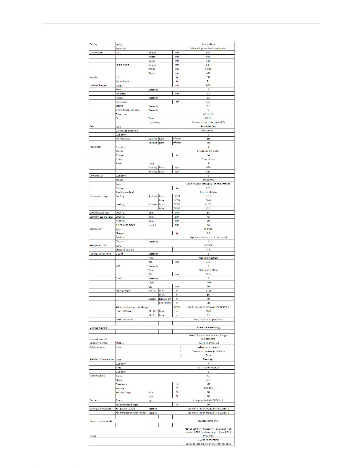
RZQG71L7Y1B
ESIE12-06 Specifications
Specifications 19
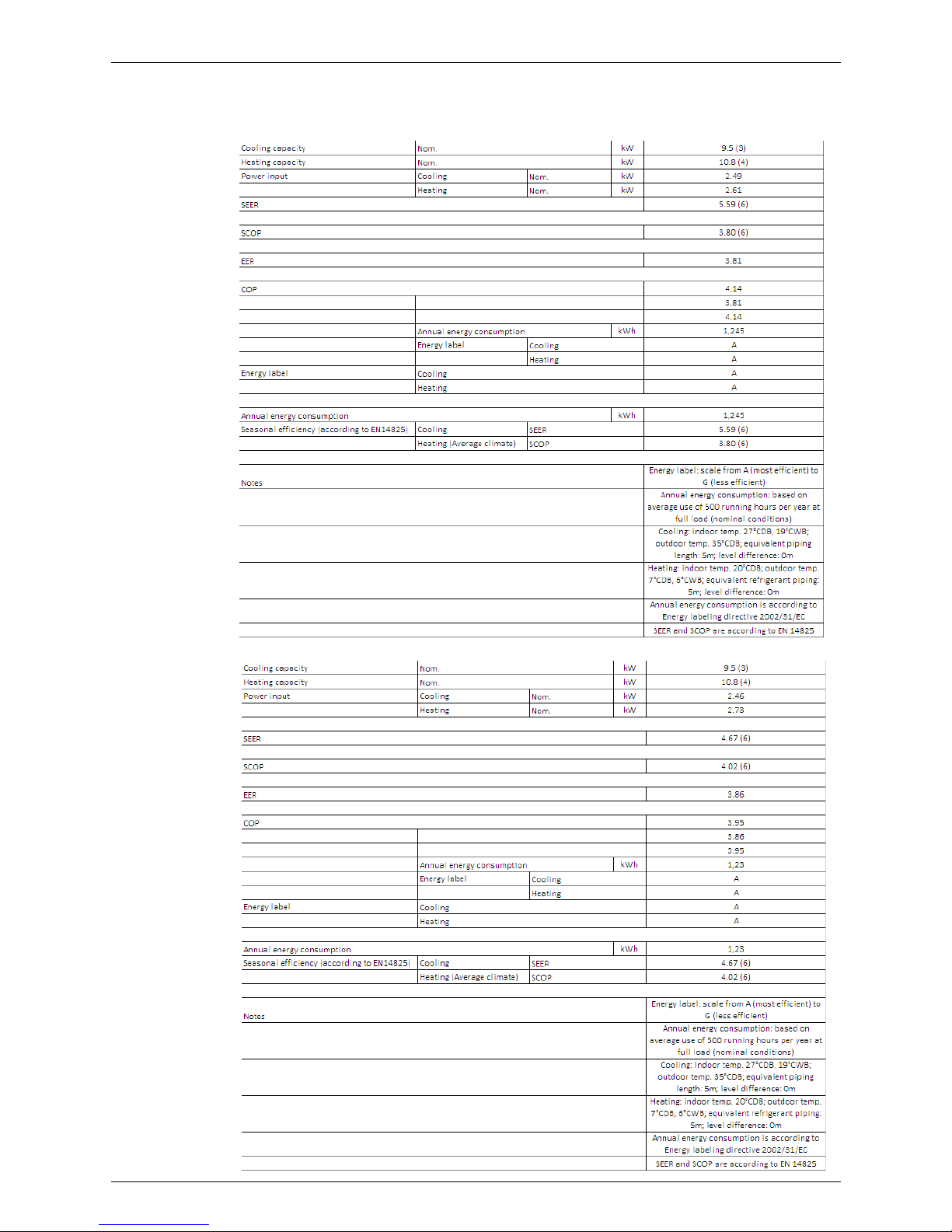
RZQG100V
FVQ100CVEB / RZQG100L7V1B
FUQ100BWV1B / RZQG100L7V1B
 Loading...