


Installer and user
reference guide
VRV IV-S system air conditioner
RXYSQ8TMY1B
RXYSQ10TMY1B
RXYSQ12TMY1B
Installer and user reference guide
VRV IV-S system air conditioner
English

Table of Contents
Table of Contents
1 General safety precautions 3
1.1 About the documentation .......................................................... 3
1.1.1 Meaning of warnings and symbols.............................. 3
1.2 For the user ............................................................................... 4
1.3 For the installer.......................................................................... 4
1.3.1 General ....................................................................... 4
1.3.2 Installation site ............................................................ 4
1.3.3 Refrigerant .................................................................. 5
1.3.4 Brine............................................................................ 5
1.3.5 Water .......................................................................... 5
1.3.6 Electrical ..................................................................... 6
2 About the documentation 6
2.1 About this document.................................................................. 6
For the installer 7
3 About the box 7
3.1 Overview: About the box ........................................................... 7
3.2 Outdoor unit............................................................................... 7
3.2.1 To unpack the outdoor unit ......................................... 7
3.2.2 To handle the outdoor unit.......................................... 7
3.2.3 To remove the accessories from the outdoor unit....... 8
3.2.4 To remove the transportation stay .............................. 8
4 About the units and options 8
4.1 Overview: About the units and options...................................... 8
4.2 Identification .............................................................................. 8
4.2.1 Identification label: Outdoor unit ................................. 8
4.3 About the outdoor unit ............................................................... 9
4.4 System layout............................................................................ 9
4.5 Combining units and options ..................................................... 9
4.5.1 About combining units and options............................. 9
4.5.2 Possible combinations of indoor units......................... 9
4.5.3 Possible options for the outdoor unit........................... 9
5 Preparation 9
5.1 Overview: Preparation............................................................... 9
5.2 Preparing installation site .......................................................... 9
5.2.1 Installation site requirements of the outdoor unit ........ 10
5.2.2 Additional installation site requirements of the
outdoor unit in cold climates ....................................... 11
5.2.3 Securing safety against refrigerant leaks.................... 11
5.3 Preparing refrigerant piping....................................................... 12
5.3.1 Refrigerant piping requirements.................................. 12
5.3.2 Refrigerant piping material.......................................... 12
5.3.3 To select the piping size ............................................. 13
5.3.4 To select refrigerant branch kits.................................. 14
5.3.5 Refrigerant piping length and height difference .......... 14
5.4 Preparing electrical wiring ......................................................... 15
5.4.1 About electrical compliance ........................................ 15
5.4.2 Safety device requirements ........................................ 15
6 Installation 16
6.1 Overview: Installation ................................................................ 16
6.2 Opening the units ...................................................................... 16
6.2.1 About opening the units .............................................. 16
6.2.2 To open the outdoor unit............................................. 16
6.3 Mounting the outdoor unit.......................................................... 16
6.3.1 About mounting the outdoor unit................................. 16
6.3.2 Precautions when mounting the outdoor unit.............. 16
6.3.3 To provide the installation structure............................ 16
6.3.4 To install the outdoor unit............................................ 17
6.3.5 To provide drainage.................................................... 17
6.3.6 To prevent the outdoor unit from falling over .............. 17
6.4 Connecting the refrigerant piping ............................................... 18
6.4.1 About connecting the refrigerant piping ....................... 18
6.4.2 Precautions when connecting the refrigerant piping.... 18
6.4.3 Pipe bending guidelines............................................... 18
6.4.4 To braze the pipe end .................................................. 18
6.4.5 Using the stop valve and service port .......................... 18
6.4.6 To remove the pinched pipes....................................... 19
6.4.7 To connect the refrigerant piping to the outdoor unit ... 20
6.4.8 To connect the refrigerant branching kit ...................... 21
6.5 Checking the refrigerant piping .................................................. 21
6.5.1 About checking the refrigerant piping .......................... 21
6.5.2 Checking refrigerant piping: General guidelines.......... 22
6.5.3 Checking refrigerant piping: Setup............................... 22
6.5.4 To perform a leak test .................................................. 22
6.5.5 To perform vacuum drying ........................................... 22
6.6 To insulate the refrigerant piping................................................ 22
6.7 Charging refrigerant ................................................................... 23
6.7.1 About charging refrigerant ........................................... 23
6.7.2 Precautions when charging refrigerant ........................ 23
6.7.3 To determine the additional refrigerant amount........... 23
6.7.4 To charge refrigerant ................................................... 24
6.7.5 Error codes when charging refrigerant......................... 25
6.7.6 To fix the fluorinated greenhouse gases label ............. 25
6.8 Connecting the electrical wiring.................................................. 25
6.8.1 About connecting the electrical wiring.......................... 25
6.8.2 Precautions when connecting electrical wiring ............ 26
6.8.3 Guidelines when knocking out knockout holes ............ 27
6.8.4 Guidelines when connecting the electrical wiring ........ 27
6.8.5 To connect the electrical wiring on the outdoor unit..... 27
6.9 Finishing the outdoor unit installation ......................................... 28
6.9.1 To finish the transmission wiring.................................. 28
6.9.2 To close the outdoor unit ............................................. 28
7 Configuration 29
7.1 Overview: Configuration ............................................................. 29
7.2 Making field settings................................................................... 29
7.2.1 About making field settings .......................................... 29
7.2.2 To access the field setting components....................... 29
7.2.3 Field setting components ............................................. 29
7.2.4 To access mode 1 or 2 ................................................ 30
7.2.5 To use mode 1 ............................................................. 30
7.2.6 To use mode 2 ............................................................. 31
7.2.7 Mode 1 (and default situation): Monitoring settings ..... 31
7.2.8 Mode 2: Field settings.................................................. 33
7.2.9 To connect the PC configurator to the outdoor unit ..... 36
7.3 Energy saving and optimum operation....................................... 36
7.3.1 Available main operation methods............................... 36
7.3.2 Available comfort settings ............................................ 37
7.3.3 Example: Automatic mode during cooling.................... 38
7.3.4 Example: Automatic mode during heating ................... 38
8 Commissioning 39
8.1 Overview: Commissioning.......................................................... 39
8.2 Precautions when commissioning .............................................. 39
8.3 Checklist before commissioning................................................. 39
8.4 Checklist during commissioning ................................................. 40
8.4.1 About test run............................................................... 40
8.4.2 To perform a test run (7-LEDs display)........................ 40
8.4.3 To perform a test run (7-segments display) ................. 40
8.4.4 Correcting after abnormal completion of the test run... 41
8.4.5 Operating the unit ........................................................ 41
9 Hand-over to the user 41
10 Maintenance and service 41
10.1 Overview: Maintenance and service .......................................... 41
10.2 Maintenance safety precautions................................................. 41
10.2.1 To prevent electrical hazards ....................................... 41
10.3 Checklist for yearly maintenance of the outdoor unit ................. 41
10.4 About service mode operation.................................................... 42
10.4.1 To use vacuum mode .................................................. 42
Installer and user reference guide
2
VRV IV-S system air conditioner
RXYSQ8~12TMY1B
4P404225-1A – 2015.11
1 General safety precautions
10.4.2 To recover refrigerant ................................................. 42
11 Troubleshooting 42
11.1 Overview: Troubleshooting........................................................ 42
11.2 Precautions when troubleshooting ............................................ 42
11.3 Solving problems based on error codes .................................... 42
11.3.1 Error codes: Overview ................................................ 42
12 Disposal 45
13 Technical data 46
13.1 Overview: Technical data .......................................................... 46
13.2 Dimensions: Outdoor unit .......................................................... 46
13.3 Service space: Outdoor unit ...................................................... 48
13.4 Components: Outdoor unit ........................................................ 50
13.5 Piping diagram: Outdoor unit..................................................... 52
13.6 Wiring diagram: Outdoor unit .................................................... 54
13.7 Technical specifications: Outdoor unit....................................... 58
13.8 Capacity table: Indoor unit......................................................... 60
For the user 61
14 About the system 61
14.1 System layout ............................................................................ 61
15 User interface 61
16 Before operation 61
17 Operation 61
17.1 Operation range ........................................................................ 61
17.2 Operating the system ................................................................ 62
17.2.1 About operating the system ........................................ 62
17.2.2 About cooling, heating, fan only, and automatic
operation ..................................................................... 62
17.2.3 About the heating operation ........................................ 62
17.2.4 To operate the system ................................................ 62
17.3 Using the dry program ............................................................... 62
17.3.1 About the dry program ................................................ 62
17.3.2 To use the dry program............................................... 62
17.4 Adjusting the air flow direction................................................... 63
17.4.1 About the air flow flap ................................................. 63
17.5 Setting the master user interface .............................................. 63
17.5.1 About setting the master user interface ...................... 63
17.5.2 To designate the master user interface (VRV DX)...... 63
17.5.3 To designate the master user interface (RA DX) ........ 63
17.5.4 About control systems................................................. 63
18 Energy saving and optimum operation 64
18.1 Available main operation methods ............................................ 64
18.2 Available comfort settings ......................................................... 64
19 Maintenance and service 64
19.1 Maintenance after a long stop period ........................................ 65
19.2 Maintenance before a long stop period ..................................... 65
19.3 About the refrigerant.................................................................. 65
19.4 After-sales service and warranty ............................................... 65
19.4.1 Warranty period .......................................................... 65
19.4.2 Recommended maintenance and inspection .............. 65
19.4.3 Recommended maintenance and inspection cycles ... 65
19.4.4 Shortened maintenance and replacement cycles ....... 66
20 Troubleshooting 66
20.1 Error codes: Overview ............................................................... 67
20.2 Symptoms that are not air conditioner troubles ......................... 67
20.2.1 Symptom: The system does not operate .................... 67
20.2.2 Symptom: Fan operation is possible, but cooling and
heating do not work..................................................... 67
20.2.3 Symptom: The fan strength does not correspond to
the setting ................................................................... 68
20.2.4 Symptom: The fan direction does not correspond to
the setting ................................................................... 68
20.2.5 Symptom: White mist comes out of a unit (Indoor
unit) .............................................................................. 68
20.2.6 Symptom: White mist comes out of a unit (Indoor
unit, outdoor unit) ......................................................... 68
20.2.7 Symptom: The user interface display reads "U4" or
"U5" and stops, but then restarts after a few minutes.. 68
20.2.8 Symptom: Noise of air conditioners (Indoor unit) ......... 68
20.2.9 Symptom: Noise of air conditioners (Indoor unit,
outdoor unit)................................................................. 68
20.2.10 Symptom: Noise of air conditioners (Outdoor unit)...... 68
20.2.11 Symptom: Dust comes out of the unit.......................... 68
20.2.12 Symptom: The units can give off odours...................... 68
20.2.13 Symptom: The outdoor unit fan does not spin ............. 68
20.2.14 Symptom: The display shows "88"............................... 68
20.2.15 Symptom: The compressor in the outdoor unit does
not stop after a short heating operation ....................... 68
20.2.16 Symptom: The inside of an outdoor unit is warm
even when the unit has stopped .................................. 68
20.2.17 Symptom: Hot air can be felt when the indoor unit is
stopped ........................................................................ 68
21 Relocation 68
22 Disposal 69
23 Glossary 69
1 General safety precautions
1.1 About the documentation
▪ The original documentation is written in English. All other
languages are translations.
▪ The precautions described in this document cover very important
topics, follow them carefully.
▪ The installation of the system, and all activities described in the
installation manual and the installer reference guide must be
performed by an authorized installer.
1.1.1 Meaning of warnings and symbols
DANGER
Indicates a situation that results in death or serious injury.
DANGER: RISK OF ELECTROCUTION
Indicates a situation that could result in electrocution.
DANGER: RISK OF BURNING
Indicates a situation that could result in burning because of
extreme hot or cold temperatures.
WARNING
Indicates a situation that could result in death or serious
injury.
CAUTION
Indicates a situation that could result in minor or moderate
injury.
NOTICE
Indicates a situation that could result in equipment or
property damage.
INFORMATION
Indicates useful tips or additional information.
RXYSQ8~12TMY1B
VRV IV-S system air conditioner
4P404225-1A – 2015.11
Installer and user reference guide
3
1 General safety precautions
1.2 For the user
▪ If you are not sure how to operate the unit, contact your installer.
▪ This appliance can be used by children aged from 8 years and
above and persons with reduced physical, sensory or mental
capabilities or lack of experience and knowledge if they have been
given supervision or instruction concerning use of the appliance in
a safe way and understand the hazards involved. Children shall
not play with the appliance. Cleaning and user maintenance shall
not be made by children without supervision.
WARNING
To prevent electric shocks or fire:
▪ Do NOT rinse the unit.
▪ Do NOT operate the unit with wet hands.
▪ Do NOT place any objects containing water on the unit.
NOTICE
▪ Do NOT place any objects or equipment on top of the
unit.
▪ Do NOT sit, climb or stand on the unit.
▪ Units are marked with the following symbol:
This means that electrical and electronic products may not be
mixed with unsorted household waste. Do NOT try to dismantle
the system yourself: the dismantling of the system, treatment of
the refrigerant, of oil and of other parts must be done by an
authorized installer and must comply with applicable legislation.
Units must be treated at a specialized treatment facility for reuse,
recycling and recovery. By ensuring this product is disposed of
correctly, you will help to prevent potential negative consequences
for the environment and human health. For more information,
contact your installer or local authority.
▪ Batteries are marked with the following symbol:
This means that the batteries may not be mixed with unsorted
household waste. If a chemical symbol is printed beneath the
symbol, this chemical symbol means that the battery contains a
heavy metal above a certain concentration.
Possible chemical symbols are: Pb: lead (>0.004%).
Waste batteries must be treated at a specialized treatment facility
for reuse. By ensuring waste batteries are disposed of correctly,
you will help to prevent potential negative consequences for the
environment and human health.
1.3 For the installer
WARNING
Make sure installation, testing and applied materials
comply with applicable legislation (on top of the
instructions described in the Daikin documentation).
CAUTION
Wear adequate personal protective equipment (protective
gloves, safety glasses,…) when installing, maintaining or
servicing the system.
WARNING
Tear apart and throw away plastic packaging bags so that
nobody, especially children, can play with them. Possible
risk: suffocation.
DANGER: RISK OF BURNING
▪ Do NOT touch the refrigerant piping, water piping or
internal parts during and immediately after operation. It
could be too hot or too cold. Give it time to return to
normal temperature. If you must touch it, wear
protective gloves.
▪ Do NOT touch any accidental leaking refrigerant.
WARNING
Provide adequate measures to prevent that the unit can be
used as a shelter by small animals. Small animals that
make contact with electrical parts can cause malfunctions,
smoke or fire.
CAUTION
Do NOT touch the air inlet or aluminum fins of the unit.
NOTICE
▪ Do NOT place any objects or equipment on top of the
unit.
▪ Do NOT sit, climb or stand on the unit.
NOTICE
Works executed on the outdoor unit are best done under
dry weather conditions to avoid water ingress.
In accordance with the applicable legislation, it might be necessary
to provide a logbook with the product containing at least: information
on maintenance, repair work, results of tests, stand-by periods,…
Also, at least, following information must be provided at an
accessible place at the product:
▪ Instructions for shutting down the system in case of an emergency
▪ Name and address of fire department, police and hospital
▪ Name, address and day and night telephone numbers for
obtaining service
In Europe, EN378 provides the necessary guidance for this logbook.
1.3.1 General
If you are not sure how to install or operate the unit, contact your
dealer.
NOTICE
Improper installation or attachment of equipment or
accessories could result in electric shock, short-circuit,
leaks, fire or other damage to the equipment. Only use
accessories, optional equipment and spare parts made or
approved by Daikin.
Installer and user reference guide
4
1.3.2 Installation site
▪ Provide sufficient space around the unit for servicing and air
circulation.
▪ Make sure the installation site withstands the unit's weight and
vibration.
▪ Make sure the area is well ventilated.
▪ Make sure the unit is level.
Do NOT install the unit in the following places:
▪ In potentially explosive atmospheres.
RXYSQ8~12TMY1B
VRV IV-S system air conditioner
4P404225-1A – 2015.11
1 General safety precautions
▪ In places where there is machinery that emits electromagnetic
waves. Electromagnetic waves may disturb the control system,
and cause malfunction of the equipment.
▪ In places where there is a risk of fire due to the leakage of
flammable gases (example: thinner or gasoline), carbon fibre,
ignitable dust.
▪ In places where corrosive gas (example: sulphurous acid gas) is
produced. Corrosion of copper pipes or soldered parts may cause
the refrigerant to leak.
1.3.3 Refrigerant
If applicable. See the installation manual or installer reference guide
of your application for more information.
NOTICE
Make sure refrigerant piping installation complies with
applicable legislation. In Europe, EN378 is the applicable
standard.
NOTICE
Make sure the field piping and connections are not
subjected to stress.
WARNING
During tests, NEVER pressurize the product with a
pressure higher than the maximum allowable pressure (as
indicated on the nameplate of the unit).
WARNING
Take sufficient precautions in case of refrigerant leakage. If
refrigerant gas leaks, ventilate the area immediately.
Possible risks:
▪ Excessive refrigerant concentrations in a closed room
can lead to oxygen deficiency.
▪ Toxic gas may be produced if refrigerant gas comes
into contact with fire.
WARNING
Always recover the refrigerant. Do NOT release them
directly into the environment. Use a vacuum pump to
evacuate the installation.
NOTICE
After all the piping has been connected, make sure there is
no gas leak. Use nitrogen to perform a gas leak detection.
NOTICE
▪ To avoid compressor breakdown, do NOT charge more
than the specified amount of refrigerant.
▪ When the refrigerant system is to be opened,
refrigerant must be treated according to the applicable
legislation.
WARNING
Make sure there is no oxygen in the system. Refrigerant
may only be charged after performing the leak test and the
vacuum drying.
▪ In case re-charge is required, refer to the nameplate of the unit. It
states the type of refrigerant and necessary amount.
▪ The unit is factory charged with refrigerant and depending on pipe
sizes and pipe lengths some systems require additional charging
of refrigerant.
▪ Only use tools exclusively for the refrigerant type used in the
system, this to ensure pressure resistance and prevent foreign
materials from entering into the system.
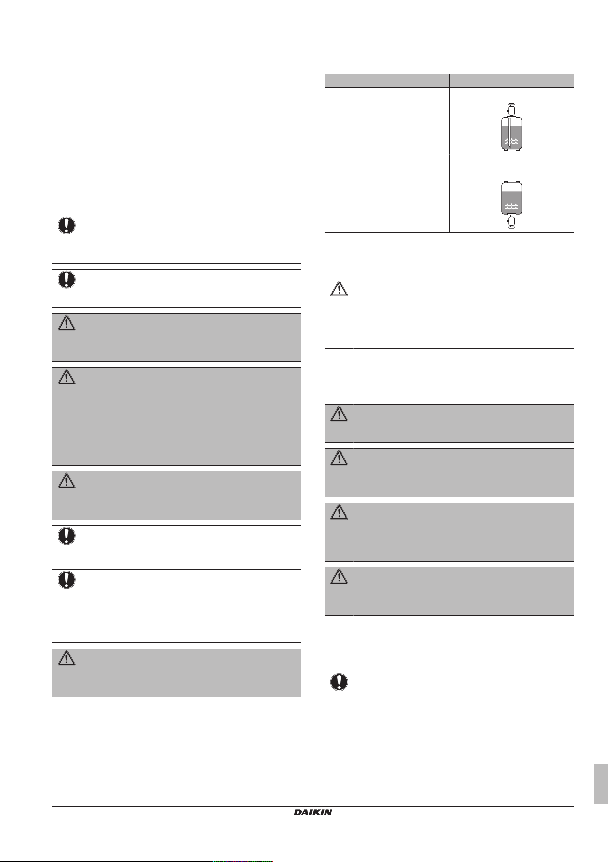
▪ Charge the liquid refrigerant as follows:
If Then
A siphon tube is present
(i.e., the cylinder is marked with
"Liquid filling siphon attached")
A siphon tube is NOT present Charge with the cylinder upside
▪ Open refrigerant cylinders slowly.
▪ Charge the refrigerant in liquid form. Adding it in gas form may
prevent normal operation.
CAUTION
When the refrigerant charging procedure is done or when
pausing, close the valve of the refrigerant tank
immediately. If the valve is not closed immediately,
remaining pressure might charge additional refrigerant.
Possible consequence: Incorrect refrigerant amount.
Charge with the cylinder upright.
down.
1.3.4 Brine
If applicable. See the installation manual or installer reference guide
of your application for more information.
WARNING
The selection of the brine MUST be in accordance with the
applicable legislation.
WARNING
Take sufficient precautions in case of brine leakage. If
brine leaks, ventilate the area immediately and contact
your local dealer.
WARNING
The ambient temperature inside the unit can get much
higher than that of the room, e.g. 70°C. In case of a brine
leak, hot parts inside the unit can create a hazardous
situation.
WARNING
The use and installation of the application MUST comply
with the safety and environmental precautions specified in
the applicable legislation.
1.3.5 Water
If applicable. See the installation manual or installer reference guide
of your application for more information.
NOTICE
Make sure water quality complies with EU directive
98/83EC.
RXYSQ8~12TMY1B
VRV IV-S system air conditioner
4P404225-1A – 2015.11
Installer and user reference guide
5
2 About the documentation
1.3.6 Electrical
DANGER: RISK OF ELECTROCUTION
▪ Turn OFF all power supply before removing the
switch box cover, connecting electrical wiring or
touching electrical parts.
▪ Disconnect the power supply for more than 1 minute,
and measure the voltage at the terminals of main circuit
capacitors or electrical components before servicing.
The voltage MUST be less than 50 V DC before you
can touch electrical components. For the location of the
terminals, see the wiring diagram.
▪ Do NOT touch electrical components with wet hands.
▪ Do NOT leave the unit unattended when the service
cover is removed.
WARNING
If NOT factory installed, a main switch or other means for
disconnection, having a contact separation in all poles
providing full disconnection under overvoltage category III
condition, shall be installed in the fixed wiring.
WARNING
▪ ONLY use copper wires.
▪ Make sure the field wiring complies with the applicable
legislation.
▪ All field wiring must be performed in accordance with
the wiring diagram supplied with the product.
▪ NEVER squeeze bundled cables and make sure they
do not come in contact with the piping and sharp
edges. Make sure no external pressure is applied to the
terminal connections.
▪ Make sure to install earth wiring. Do NOT earth the unit
to a utility pipe, surge absorber, or telephone earth.
Incomplete earth may cause electrical shock.
▪ Make sure to use a dedicated power circuit. NEVER
use a power supply shared by another appliance.
▪ Make sure to install the required fuses or circuit
breakers.
▪ Make sure to install an earth leakage protector. Failure
to do so may cause electric shock or fire.
▪ When installing the earth leakage protector, make sure
it is compatible with the inverter (resistant to high
frequency electric noise) to avoid unnecessary opening
of the earth leakage protector.
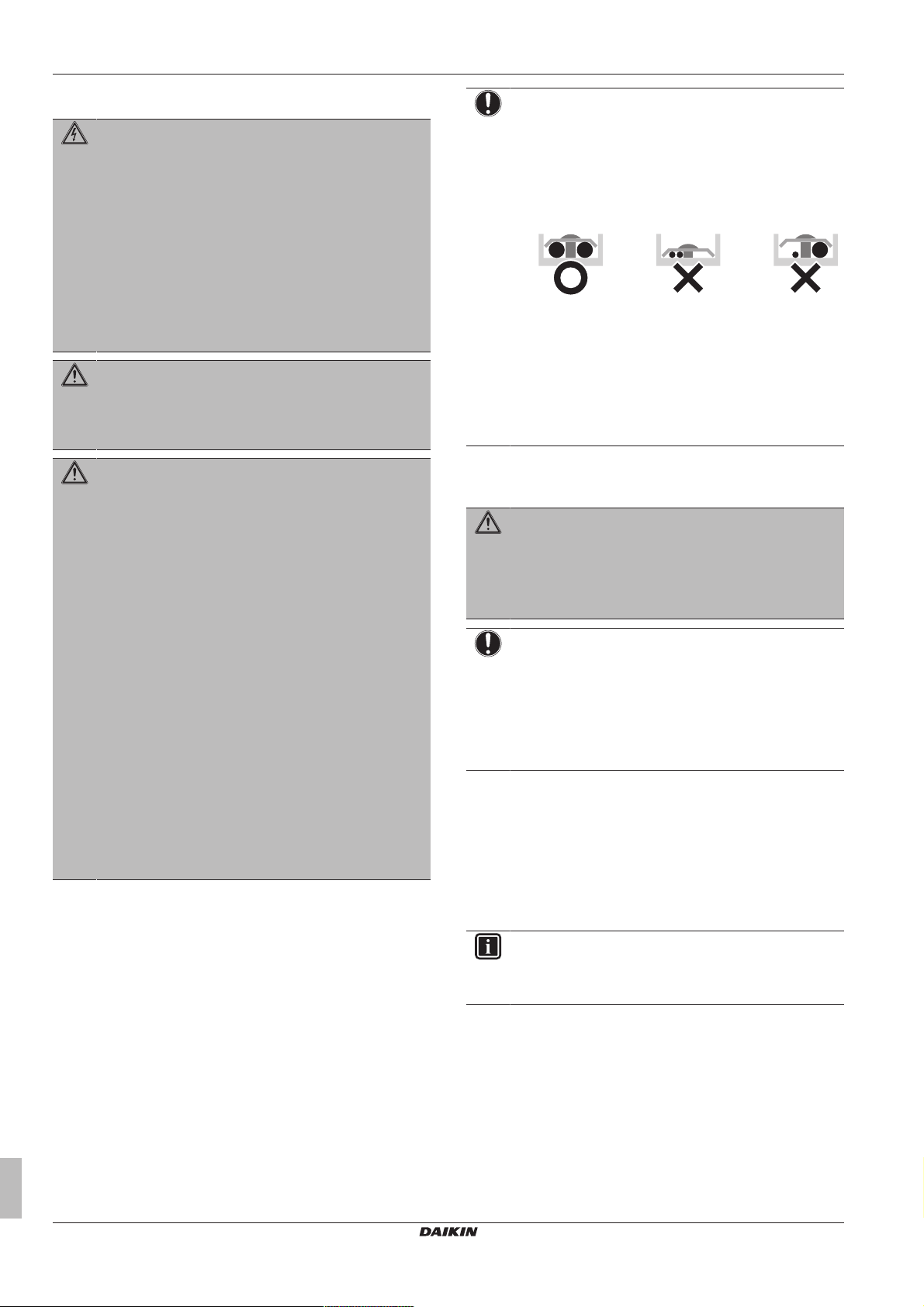
NOTICE
Precautions when laying power wiring:
▪ Do not connect wiring of different thicknesses to the
power terminal block (slack in the power wiring may
cause abnormal heat).
▪ When connecting wiring which is the same thickness,
do as shown in the figure below.
▪ For wiring, use the designated power wire and connect
firmly, then secure to prevent outside pressure being
exerted on the terminal board.
▪ Use an appropriate screwdriver for tightening the
terminal screws. A screwdriver with a small head will
damage the head and make proper tightening
impossible.
▪ Over-tightening the terminal screws may break them.
Install power cables at least 1metre away from televisions or radios
to prevent interference. Depending on the radio waves, a distance of
1metre may not be sufficient.
WARNING
▪ After finishing the electrical work, confirm that each
electrical component and terminal inside the electrical
components box is connected securely.
▪ Make sure all covers are closed before starting up the
unit.
NOTICE
Only applicable if the power supply is three‑phase, and the
compressor has an ON/OFF starting method.
If there exists the possibility of reversed phase after a
momentary black out and the power goes on and off while
the product is operating, attach a reversed phase
protection circuit locally. Running the product in reversed
phase can break the compressor and other parts.
2 About the documentation
2.1 About this document
Target audience
Authorised installers + end users
Installer and user reference guide
6
INFORMATION
This appliance is intended to be used by expert or trained
users in shops, in light industry and on farms, or for
commercial use by lay persons.
Documentation set
This document is part of a documentation set. The complete set
consists of:
▪ General safety precautions:
▪ Safety instructions that you must read before installing
▪ Format: Paper (in the box of the outdoor unit)
▪ Outdoor unit installation and operation manual:
▪ Installation and operation instructions
▪ Format: Paper (in the box of the outdoor unit)
RXYSQ8~12TMY1B
VRV IV-S system air conditioner
4P404225-1A – 2015.11
3 About the box
2
1
3
1
2
1×
8 HP
2
1
4×
10+12 HP
c
b
a
b
d
▪ Installer and user reference guide:
▪ Preparation of the installation, technical specifications,
reference data,…
▪ Detailed step-by-step instructions and background information
for basic and advanced usage
For the installer
3 About the box
3.1 Overview: About the box
This chapter describes what you have to do after the box with the
outdoor unit is delivered on-site.
It contains information about:
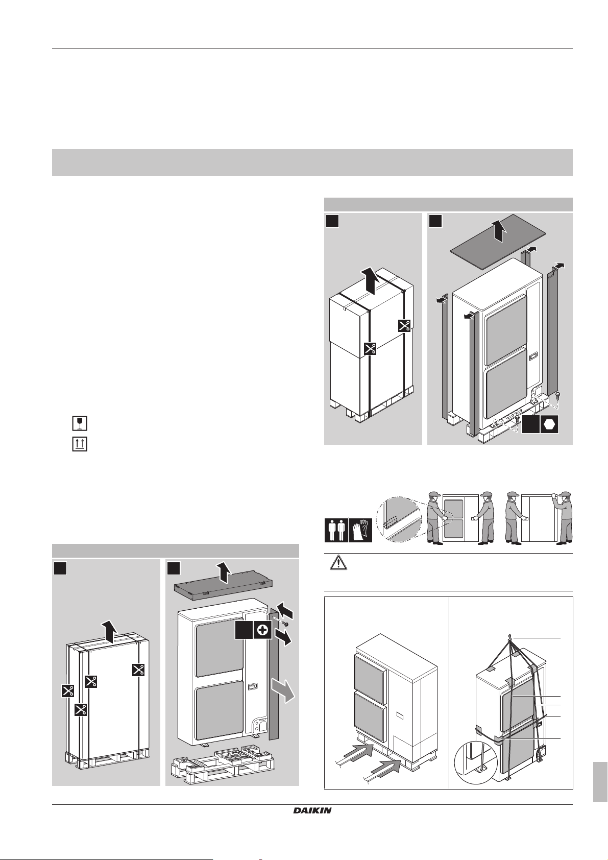
▪ Unpacking and handling the units
▪ Removing the accessories from the units
▪ Removing the transportation stay
Keep the following in mind:
▪ At delivery, the unit must be checked for damage. Any damage
must be reported immediately to the carrier's claims agent.
▪ Bring the packed unit as close as possible to its final installation
position to prevent damage during transport.
▪ When handling the unit, take into account the following:
▪ Format: Digital files on http://www.daikineurope.com/support-
and-manuals/product-information/
Latest revisions of the supplied documentation may be available on
the regional Daikin website or via your dealer.
The original documentation is written in English. All other languages
are translations.
Fragile, handle the unit with care.
Keep the unit upright in order to avoid compressor
damage.
▪ Choose on beforehand the path along which the unit is to be
brought in.
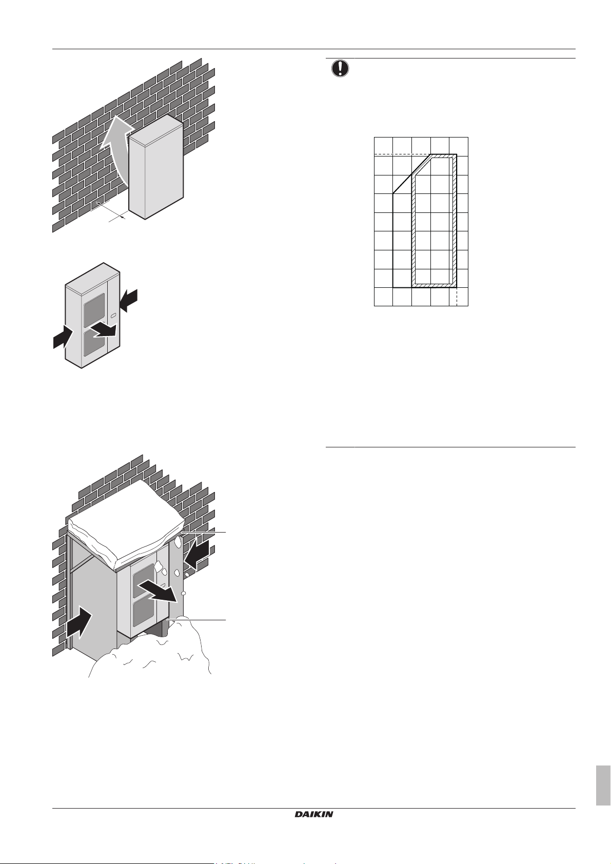
3.2.2 To handle the outdoor unit
Carry the unit slowly as shown:
3.2 Outdoor unit
3.2.1 To unpack the outdoor unit
CAUTION
To avoid injury, do NOT touch the air inlet or aluminum fins
of the unit.
Forklift. As long as the unit
remains on its pallet, you can
also use a forklift.
Crane. In case of RXYSQ10+12,
you can also use a crane and lift
the unit as follows:
RXYSQ8~12TMY1B
VRV IV-S system air conditioner
4P404225-1A – 2015.11
Installer and user reference guide
7
4 About the units and options
8 HP 10+12 HP
a
1×
b
1×
c
1×
d
1×
2× (8 HP)
5× (=2+3) (10+12 HP)
1×
e f g
1×
1
3 (12.3 N·m)3 (12.3 N·m)
2
2
1
a
b
a Lifting hook
b 2 vertical ropes (at least 8m and Ø20mm) to lift the unit
c 1 horizontal rope (also fixed to the lifting hook) to prevent
the unit from dropping
d Protective material (rags, soft material) between the ropes
and the casing to protect the casing
WARNING
The unit's center of gravity deviates to the right side
(compressor side). If you lift the unit using a crane and you
do not fix a horizontal rope to the lifting hook as shown, the
unit might drop.
3.2.3 To remove the accessories from the outdoor unit
1 Remove the service cover. See "6.2.2 To open the outdoor
unit"on page16.
2 Remove the accessories.
4 About the units and options
4.1 Overview: About the units and options
This chapter contains information about:
▪ Identification of the outdoor unit.
▪ Where the outdoor unit fits in the system layout.
▪ With which indoor units and options you can combine the outdoor
units.
a General safety precautions
b Outdoor unit installation and operation manual
c Fluorinated greenhouse gases label
d Installation information sticker
e Gas piping accessory 1 (8HP:Ø19.1mm;
10HP:Ø22.2mm; 12HP:Ø25.4mm)
f Gas piping accessory 2 (8HP:Ø19.1mm;
10HP:Ø22.2mm; 12HP:Ø25.4mm)
g Cable tie
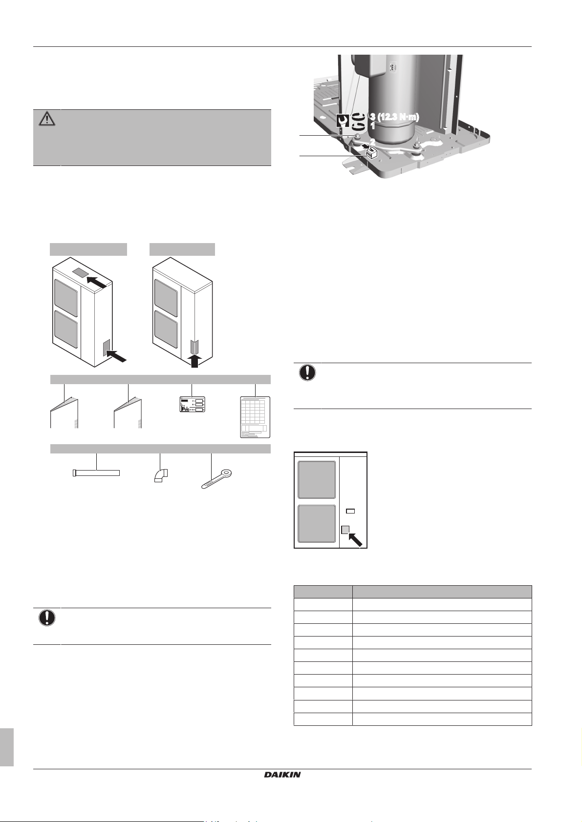
3.2.4 To remove the transportation stay
Only for RXYSQ10+12.
NOTICE
If the unit is operated with the transportation stay attached,
abnormal vibration or noise may be generated.
The transportation stay installed over the compressor leg for
protecting the unit during transport must be removed. Proceed as
shown in the figure and procedure below.
1 Slightly loosen the fixing nut (a).
2 Remove the transportation stay (b) as shown in the figure
below.
3 Tighten the fixing nut (a) again.
4.2 Identification
NOTICE
When installing or servicing several units at the same time,
make sure NOT to switch the service panels between
different models.
4.2.1 Identification label: Outdoor unit
Location
Model identification
Example: R X Y S Q 12 TM Y1 B [*]
Code Explanation
R Outdoor air cooled
X Heat pump (no continuous heating)
Y Single module
S S series
Q Refrigerant R410A
8~12 Capacity class
TM VRV IV series
Y1 Power supply
B European market
[*] Minor model change indication
Installer and user reference guide
8
VRV IV-S system air conditioner
RXYSQ8~12TMY1B
4P404225-1A – 2015.11
5 Preparation
g
d d
c c
f
eb
a
g
f
e
4.3 About the outdoor unit
This installation manual concerns the VRV IV-S, full inverter driven,
heat pump system.
These units are intended for outdoor installation and aimed for air to
air heat pump applications.
Specification RXYSQ8~12
Capacity Heating 25.0~37.5kW
Cooling 22.4~33.5kW
Ambient design
temperature
Heating –20~15.5°CWB
Cooling –5~52°CDB
4.4 System layout
NOTICE
Design of the system must not be done at temperatures
below –15°C.
INFORMATION
Not all combinations of indoor units are allowed, for
guidance, see "4.5.2 Possible combinations of indoor
units"on page9.
▪ SA/RA (Sky Air/Residential Air) direct expansion (DX) indoor units
(air to air applications). Further referred to as RADX indoor units.
These indoor units require a BP box.
▪ AHU (air to air applications): EKEXV-kit+EKEQ-box are required,
depending on application.
▪ Aircurtain (air to air applications): CYV/CAV (Biddle) series,
depending on application.
INFORMATION
▪ Combination of VRVDX and RADX indoor units is not
allowed.
▪ Combination of RA DX and AHU indoor units is not
allowed.
▪ Combination of RADX and aircurtain indoor units is not
allowed.
4.5.3 Possible options for the outdoor unit
INFORMATION
Refer to the technical engineering data for the latest option
names.
Refrigerant branching kit
Description Model name
Refnet header KHRQ22M29H
KHRQ22M64H
Refnet joint KHRQ22M20T
KHRQ22M29T9
KHRQ22M64T
For the selection of the optimal branching kit, please refer to
"5.3.4To select refrigerant branch kits"on page14.
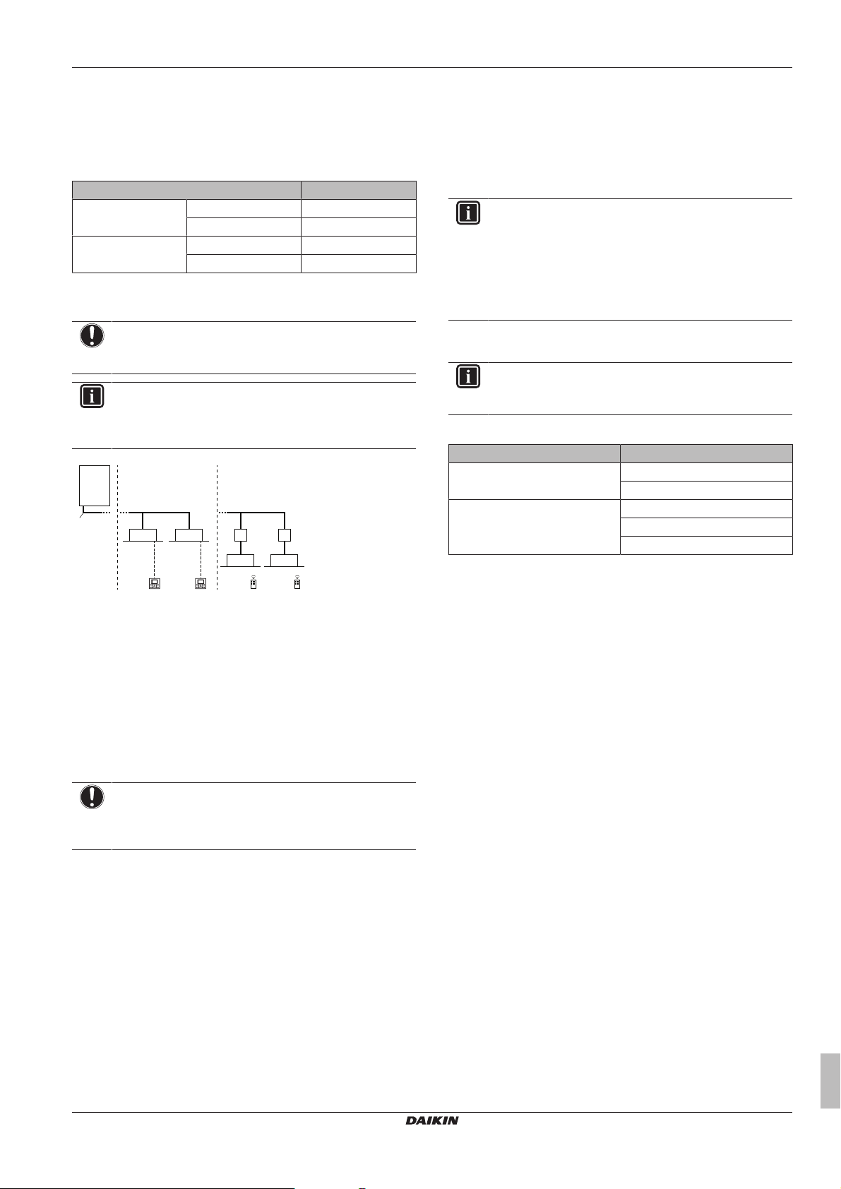
a VRV IV-S Heat pump outdoor unit
b Refrigerant piping
c VRV direct expansion (DX) indoor unit
d User interface (dedicated depending on indoor unit type)
e BP box (required to connect Residential Air (RA) or Sky Air
(SA) direct expansion (DX) indoor units)
f Residential Air (RA) direct expansion (DX) indoor units
g User interface (wireless, dedicated depending on indoor
unit type)
4.5 Combining units and options
4.5.1 About combining units and options
NOTICE
To be sure your system setup (outdoor unit+indoor unit(s))
will work, you have to consult the latest technical
engineering data for VRV IV-S heat pump.
The VRV IV-S heat pump system can be combined with several
types of indoor units and is intended for R410A use only.
For an overview which units are available you can consult the
product catalogue for VRV IV-S.
An overview is given indicating the allowed combinations of indoor
units and outdoor units. Not all combinations are allowed. They are
subject to rules (combination between outdoor-indoor, combinations
between indoor units, etc.) mentioned in the technical engineering
data.
External control adaptor (DTA104A61/62)
To instruct specific operation with an external input coming from a
central control the external control adaptor can be used. Instructions
(group or individual) can be instructed for low noise operation and
power consumption limitation operation.
The external control adapter has to be installed in the indoor unit.
PC configurator cable (EKPCCAB)
You can make several commissioning field settings through a
personal computer interface. For this option EKPCCAB is required
which is a dedicated cable to communicate with the outdoor unit.
The user interface software is available on http://
www.daikineurope.com/support-and-manuals/software-downloads/.
5 Preparation
5.1 Overview: Preparation
This chapter describes what you have to do and know before going
on-site.
It contains information about:
▪ Preparing the installation site
▪ Preparing the refrigerant piping
▪ Preparing the electrical wiring
4.5.2 Possible combinations of indoor units
In general following type of indoor units can be connected to a VRV
IV-S heat pump system. The list is non-exhaustive and is depending
on both outdoor unit model and indoor unit model combinations.
▪ VRV direct expansion (DX) indoor units (air to air applications).
5.2 Preparing installation site
Do NOT install the unit in places often used as work place. In case
of construction works (e.g. grinding works) where a lot of dust is
created, the unit must be covered.
RXYSQ8~12TMY1B
VRV IV-S system air conditioner
4P404225-1A – 2015.11
Installer and user reference guide
9
5 Preparation
b
c
f
d
d
a
c
b e
(mm)
b
c
a
a
b
c
d
c
d
Choose the installation location with sufficient place for carrying the
unit in and out of the site.
5.2.1 Installation site requirements of the outdoor unit
INFORMATION
Also read the following requirements:
▪ General installation site requirements. See the
"General safety precautions" chapter.
▪ Service space requirements. See the "Technical data"
chapter.
▪ Refrigerant piping requirements (length, height
difference). See further in this "Preparation" chapter.
CAUTION
Appliance not accessible to the general public, install it in a
secured area, protected from easy access.
This unit, both indoor and outdoor, is suitable for
installation in a commercial and light industrial
environment.
NOTICE
This is a class A product. In a domestic environment this
product may cause radio interference in which case the
user may be required to take adequate measures.
▪ Sound sensitive areas (e.g. near a bedroom and the like), so that
the operation noise will cause no trouble.
Note: If the sound is measured under actual installation
conditions, the measured value might be higher than the sound
pressure level mentioned in Sound spectrum in the data book due
to environmental noise and sound reflections.
▪ In places where a mineral oil mist, spray or vapour may be
present in the atmosphere. Plastic parts may deteriorate and fall
off or cause water leakage.
It is NOT recommended to install the unit in the following places
because it may shorten the life of the unit:
▪ Where the voltage fluctuates a lot
▪ In vehicles or vessels
▪ Where acidic or alkaline vapour is present
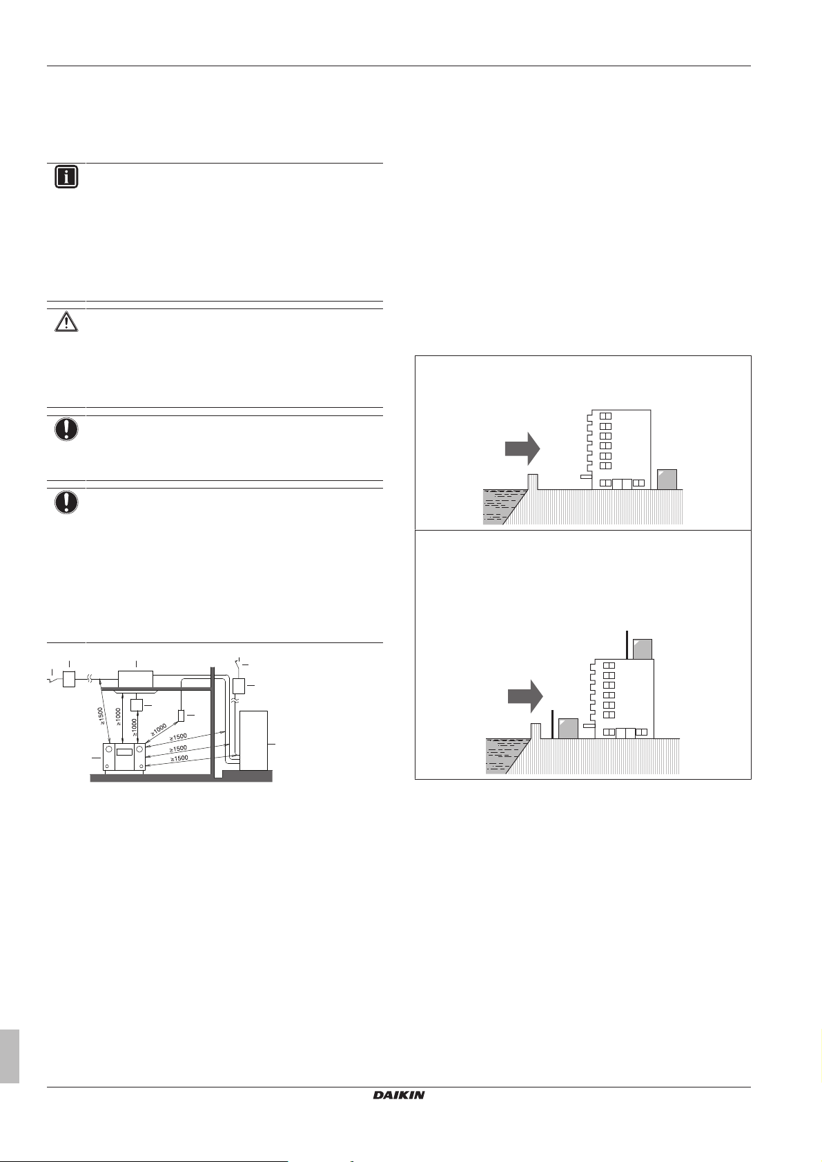
Seaside installation. Make sure the outdoor unit is NOT directly
exposed to sea winds. This is to prevent corrosion caused by high
levels of salt in the air, which might shorten the life of the unit.
Install the outdoor unit away from direct sea winds.
Example: Behind the building.
NOTICE
The equipment described in this manual may cause
electronic noise generated from radio-frequency energy.
The equipment complies to specifications that are
designed to provide reasonable protection against such
interference. However, there is no guarantee that
interference will not occur in a particular installation.
It is therefore recommended to install the equipment and
electric wires keeping proper distances away from stereo
equipment, personal computers, etc.
a Personal computer or radio
b Fuse
c Earth leakage protector
d User interface
e Indoor unit
f Outdoor unit
In places with weak reception, keep distances of 3 m or more to
avoid electromagnetic disturbance of other equipment and use
conduit tubes for power and transmission lines.
▪ Select a place where rain can be avoided as much as possible.
▪ Take care that in the event of a water leak, water cannot cause
any damage to the installation space and surroundings.
▪ Choose a location where the hot/cold air discharged from the unit
or the operation noise, will NOT disturb anyone.
▪ Heat exchanger fins are sharp and injury is possible. Choose an
installation location where there is no risk for injury (especially in
areas where children play).
Do NOT install the unit in the following places:
Installer and user reference guide
10
If the outdoor unit is exposed to direct sea winds, install a
windbreaker.
▪ Height of windbreaker≥1.5×height of outdoor unit
▪ Mind the service space requirements when installing the
windbreaker.
a Sea wind
b Building
c Outdoor unit
d Windbreaker
Strong winds (≥18 km/h) blowing against the outdoor unit’s air outlet
causes short circuit (suction of discharge air). This may result in:
▪ deterioration of the operational capacity;
▪ frequent frost acceleration in heating operation;
▪ disruption of operation due to decrease of low pressure or
increase of high pressure;
▪ a broken fan (if a strong wind blows continuously on the fan, it
may start rotating very fast, until it breaks).
It is recommended to install a baffle plate when the air outlet is
exposed to wind.
Turn the air outlet side towards the building's wall, fence or screen.
RXYSQ8~12TMY1B
VRV IV-S system air conditioner
4P404225-1A – 2015.11
a
a Make sure there is enough installation space
a
a
b
a
b
c
c
d
T
AO
(°C WB)
a b
20
15.5
15
10
5
0
–5
–10
–15
–20
10 15 20 25
27
30
T
AI
(°C DB)
Set the air outlet side at a right angle to the direction of the wind.
5 Preparation
NOTICE
When operating the unit in heating in a low outdoor
ambient temperature with high humidity conditions, make
sure to take precautions to keep the drain holes of the unit
free by using proper equipment.
In heating:
a Prevailing wind direction
b Air outlet
5.2.2 Additional installation site requirements of the outdoor unit in cold climates
Protect the outdoor unit against direct snowfall and take care that the
outdoor unit is NEVER snowed up.
a Snow cover or shed
b Pedestal (minimum height = 150mm)
c Prevailing wind direction
d Air outlet
RXYSQ8~12TMY1B
VRV IV-S system air conditioner
4P404225-1A – 2015.11
a Warming up operation range
b Operation range
TAI Ambient indoor temperature
TAO Ambient outdoor temperature
If the unit is selected to operate at ambient temperatures
lower than –5°C for 5 days or longer, with relative humidity
levels exceeding 95%, we recommend to apply a Daikin
range specifically designed for such application and/or to
contact your dealer for further advice.
5.2.3 Securing safety against refrigerant leaks
About safety against refrigerant leaks
The installer and system specialist shall secure safety against
leakage according to local regulations or standards. The following
standards may be applicable if local regulations are not available.
This system uses R410A as refrigerant. R410A itself is an entirely
safe non-toxic, non-combustible refrigerant. Nevertheless care must
be taken to ensure that air conditioning facilities are installed in a
room which is sufficiently large. This assures that the maximum
concentration level of refrigerant gas is not exceeded, in the unlikely
event of major leak in the system and this in accordance to the local
applicable regulations and standards.
About the maximum concentration level
The maximum charge of refrigerant and the calculation of the
maximum concentration of refrigerant is directly related to the
humanly occupied space in to which it could leak.
The unit of measurement of the concentration is kg/m3 (the weight in
kg of the refrigerant gas in 1m3 volume of the occupied space).
Compliance to the local applicable regulations and standards for the
maximum allowable concentration level is required.
According to the appropriate European Standard, the maximum
allowed concentration level of refrigerant to a humanly space for
R410A is limited to 0.44 kg/m3.
Installer and user reference guide
11
5 Preparation
b
a
a
b
t
Ø
a Direction of the refrigerant flow
b Room where refrigerant leak has occurred (outflow of all
the refrigerant from the system)
Pay special attention to places, such as basements etc., where
refrigerant can stay, since refrigerant is heavier than air.
To check the maximum concentration level
Check the maximum concentration level in accordance with steps 1
to 4 below and take whatever action is necessary to comply.
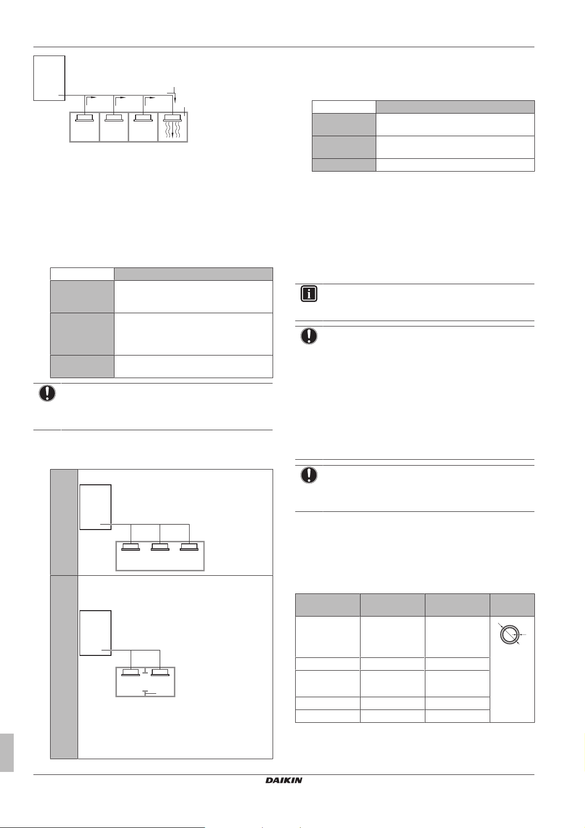
1 Calculate the amount of refrigerant (kg) charged to each system
separately.
Formula A+B=C
A Amount of refrigerant in a single unit system
(amount of refrigerant with which the system
is charged before leaving the factory)
B Additional charging amount (amount of
refrigerant added locally in accordance with
the length or diameter of the refrigerant
piping)
C Total amount of refrigerant (kg) in the
system
NOTICE
Where a single refrigerant facility is divided into 2 entirely
independent refrigerant systems, use the amount of
refrigerant with which each separate system is charged.
2 Calculate the volume of the room (m3) where the indoor unit is
installed. In a case such as the following, calculate the volume
of (D), (E) as a single room or as the smallest room.
D Where there are no smaller room divisions:
3 Calculate the refrigerant density using the results of the
calculations in steps 1 and 2 above. If the result of the above
calculation exceeds the maximum concentration level, a
ventilation opening to the adjacent room shall be made.
Formula F/G≤H
F Total volume of refrigerant in the refrigerant
system
G Size (m3) of smallest room in which there is
an indoor unit installed
H Maximum concentration level (kg/m3)
4 Calculate the refrigerant density taking the volume of the room
where the indoor unit is installed and the adjacent room. Install
ventilation openings in the door of adjacent rooms until the
refrigerant density is smaller than the maximum concentration
level.
5.3 Preparing refrigerant piping
5.3.1 Refrigerant piping requirements
INFORMATION
Also read the precautions and requirements in the
"General safety precautions" chapter.
NOTICE
The refrigerant R410A requires strict cautions for keeping
the system clean, dry and tight.
▪ Clean and dry: foreign materials (including mineral oils
or moisture) should be prevented from getting mixed
into the system.
▪ Tight: R410A does not contain any chlorine, does not
destroy the ozone layer, and does not reduce earth's
protection against harmful ultraviolet radiation. R410A
can contribute slightly to the greenhouse effect if it is
released. Therefore we should take special attention to
check the tightness of the installation.
NOTICE
The piping and other pressure-containing parts shall be
suitable for refrigerant. Use phosphoric acid deoxidised
seamless copper for refrigerant.
▪ Foreign materials inside pipes (including oils for fabrication) must
be ≤30 mg/10 m.
5.3.2 Refrigerant piping material
▪ Piping material: Phosphoric acid deoxidised seamless copper.
E Where there is a room division, but there is an opening
between the rooms sufficiently large to permit a free
flow of air back and forth.
a Opening between the rooms
b Partition (Where there is an opening without a door
or where there are openings above and below the door
which are each equivalent in size to 0.15% or more of
the floor area.)
Installer and user reference guide
12
▪ Piping temper grade and thickness:
Outer diameter
(Ø)
6.4mm (1/4")
9.5mm (3/8")
12.7mm (1/2")
15.9mm (5/8") Annealed (O) ≥0.99mm
19.1mm (3/4")
22.2mm (7/8")
25.4mm (1") Half hard (1/2H) ≥0.88mm
28.6mm (1‑1/8") Half hard (1/2H) ≥0.99mm
(a) Depending on the applicable legislation and the unit's
Temper grade Thickness (t)
Annealed (O) ≥0.80mm
Half hard (1/2H) ≥0.80mm
maximum working pressure (see "PS High" on the unit
name plate), larger piping thickness might be required.
VRV IV-S system air conditioner
(a)
RXYSQ8~12TMY1B
4P404225-1A – 2015.11
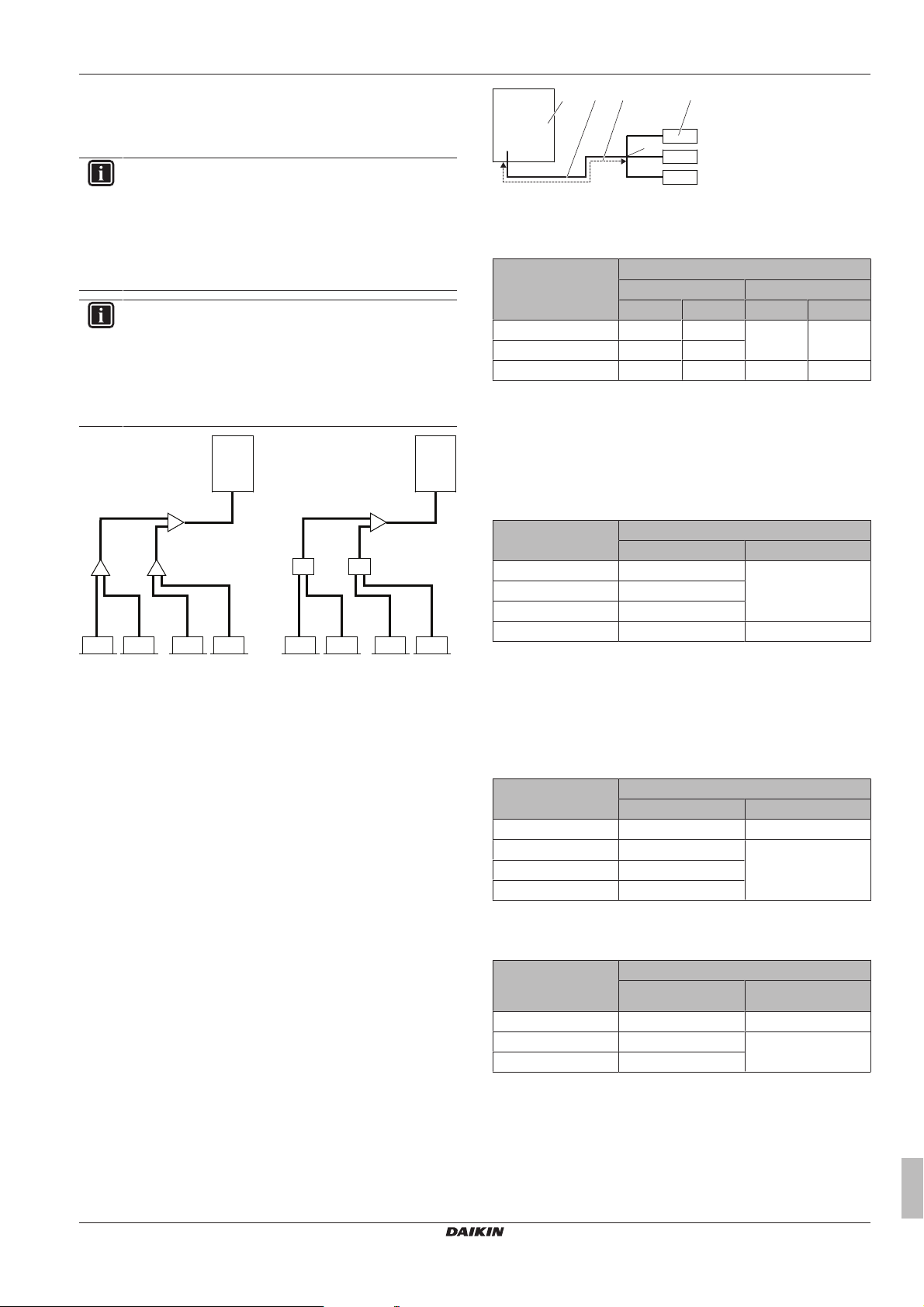
5.3.3 To select the piping size
A
B-1 B-2
C-1 C-2 C-3 C-4 E E E E
1 1
3-1 3-2 3-3 3-4
A
D
RA DXVRV DX
D
4
4
5 5 5 5
2 2
2 2
a
e
b c
d
Determine the proper size referring to following tables and reference
figure (only for indication).
INFORMATION
▪ Combination of VRVDX and RADX indoor units is not
allowed.
▪ Combination of RA DX and AHU indoor units is not
allowed.
▪ Combination of RADX and aircurtain indoor units is not
allowed.
INFORMATION
In case of RXYSQ8: If you install RADX indoor units, you
have to configure field setting [2‑41] (= type of installed
indoor units). See "7.2.8 Mode 2: Field settings" on
page33.
In case of RXYSQ10+12: The type of indoor units is
detected automatically.
5 Preparation
a Outdoor unit
b Main pipes
c Increase
d First refrigerant branch kit
e Indoor unit
Outdoor unit
capacity type (HP)
8 19.1 22.2 9.5 12.7
10 22.2 25.4
12 25.4
(a) If size is NOT available, increase is NOT allowed.
(b) If size is NOT available, increase to 28.6mm is allowed.
B: Piping between refrigerant branch kits
Choose from the following table in accordance with the indoor unit
total capacity type, connected downstream. Do not let the
connection piping exceed the refrigerant piping size chosen by the
general system model name.
Piping outer diameter size (mm)
Gas pipe Liquid pipe
Standard Size-up Standard Size-up
(a)
(b)
28.6 12.7 15.9
1 Outdoor unit
2 Refrigerant branch kits
3-1~3-4 VRVDX indoor units
4 BP units
5 RADX indoor units
A Piping between outdoor unit and (first) refrigerant branch
B-1 B-2 Piping between refrigerant branch kits
C-1~C-4 Piping between refrigerant branch kit and indoor unit
kit
D Piping between refrigerant branch kit and BP unit
E Piping between BP unit and RADX indoor unit
In case the required pipe sizes (inch sizes) are not available, it is
also allowed to use other diameters (mm sizes), taken the following
into account:
▪ Select the pipe size nearest to the required size.
▪ Use the suitable adapters for the change-over from inch tomm
pipes (field supply).
▪ The additional refrigerant calculation has to be adjusted as
mentioned in "6.7.3 To determine the additional refrigerant
amount"on page23.
A: Piping between outdoor unit and (first) refrigerant branch kit
When the equivalent pipe length between outdoor and indoor units is
90m or more, the size of the main pipes (both gas side and liquid
side) must be increased. Depending on the length of the piping, the
capacity may drop, but even in such a case the size of the main
pipes has to be increased. More specifications can be found in the
technical engineering data book.
Indoor unit capacity
index
Piping outer diameter size (mm)
Gas pipe Liquid pipe
<150 15.9 9.5
150≤x<200 19.1
200≤x<290 22.2
290≤x<390 28.6 12.7
Example: Downstream capacity for B-1 = capacity index of unit 3-1
+ capacity index of unit 3-2
C: Piping between refrigerant branch kit and indoor unit
Use the same diameters as the connections (liquid, gas) on the
indoor units. The diameters of the indoor units are as follows:
Indoor unit capacity
index
Piping outer diameter size (mm)
Gas pipe Liquid pipe
15~50 12.7 6.4
63~140 15.9 9.5
200 19.1
250 22.2
D: Piping between refrigerant branch kit and BP unit
Total capacity index
of connected indoor
units
15~62 12.7 6.4
63~149 15.9 9.5
150~208 19.1
Piping outer diameter size (mm)
Gas pipe Liquid pipe
RXYSQ8~12TMY1B
VRV IV-S system air conditioner
4P404225-1A – 2015.11
Installer and user reference guide
13
5 Preparation
E: Piping between BP unit and RA DX indoor unit
Indoor unit capacity
index
15~42 9.5 6.4
50 12.7
60 9.5
71 15.9
Piping outer diameter size (mm)
Gas pipe Liquid pipe
5.3.4 To select refrigerant branch kits
For piping example, refer to "5.3.3 To select the piping size" on
page13.
Refnet joint at first branch (counting from outdoor unit)
When using refnet joints at the first branch counted from the outdoor
unit side, choose from the following table in accordance with the
capacity of the outdoor unit. Example: Refnet joint A→B‑1.
Outdoor unit capacity type
(HP)
8+10 KHRQ22M29T9
12 KHRQ22M64T
Refrigerant branch kit
Refnet joints at other branches
For refnet joints other than the first branch, select the proper branch
kit model based on the total capacity index of all indoor units
connected after the refrigerant branch. Example: Refnet joint
B‑1→C‑1.
Indoor unit capacity index Refrigerant branch kit
<200 KHRQ22M20T
200≤x<290 KHRQ22M29T9
290≤x<390 KHRQ22M64T
Refnet headers
Concerning refnet headers, choose from the following table in
accordance with the total capacity of all the indoor units connected
below the refnet header.
Indoor unit capacity index Refrigerant branch kit
<200 KHRQ22M29H
200≤x<290
290≤x<390 KHRQ22M64H
INFORMATION
Maximum 8 branches can be connected to a header.
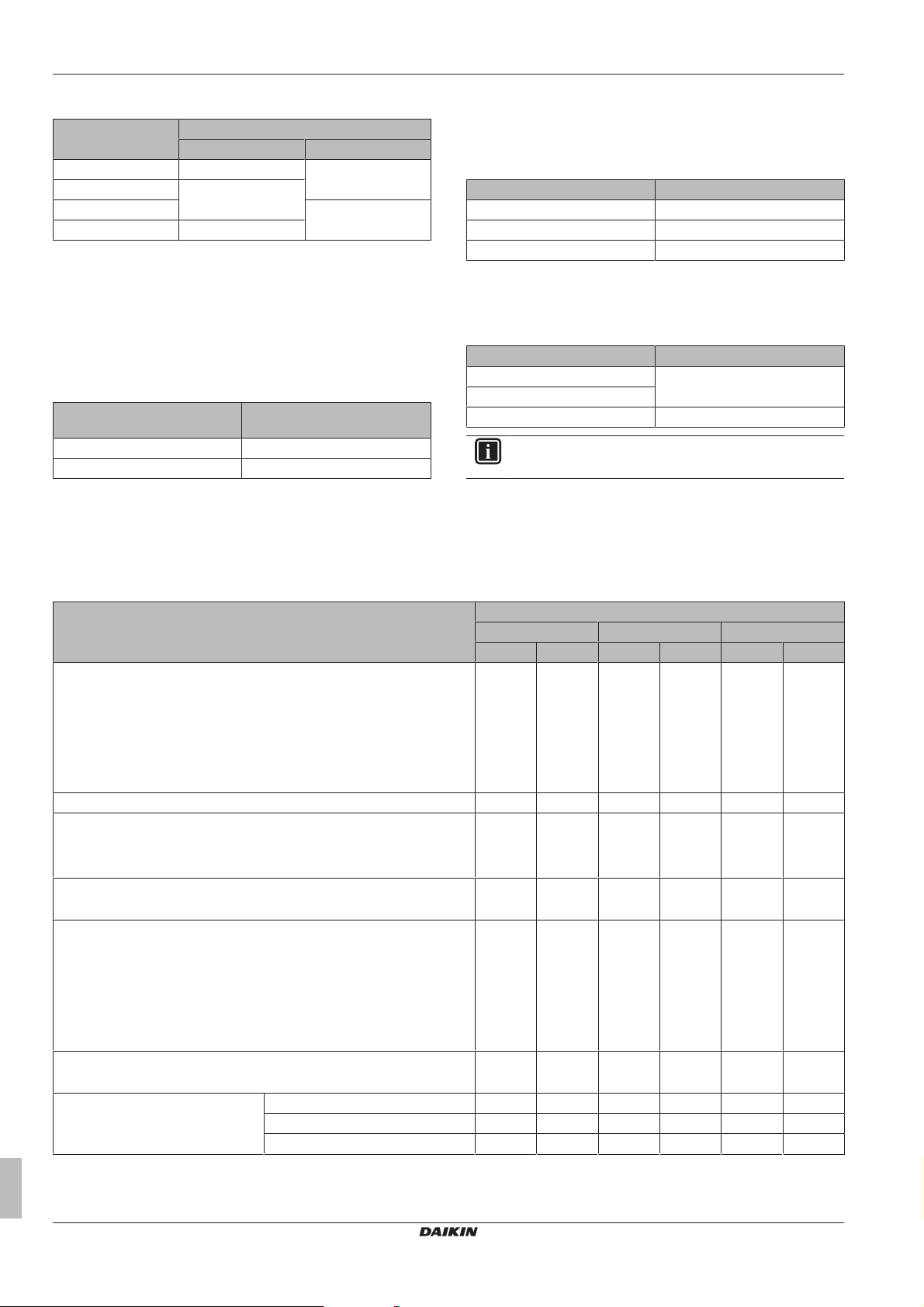
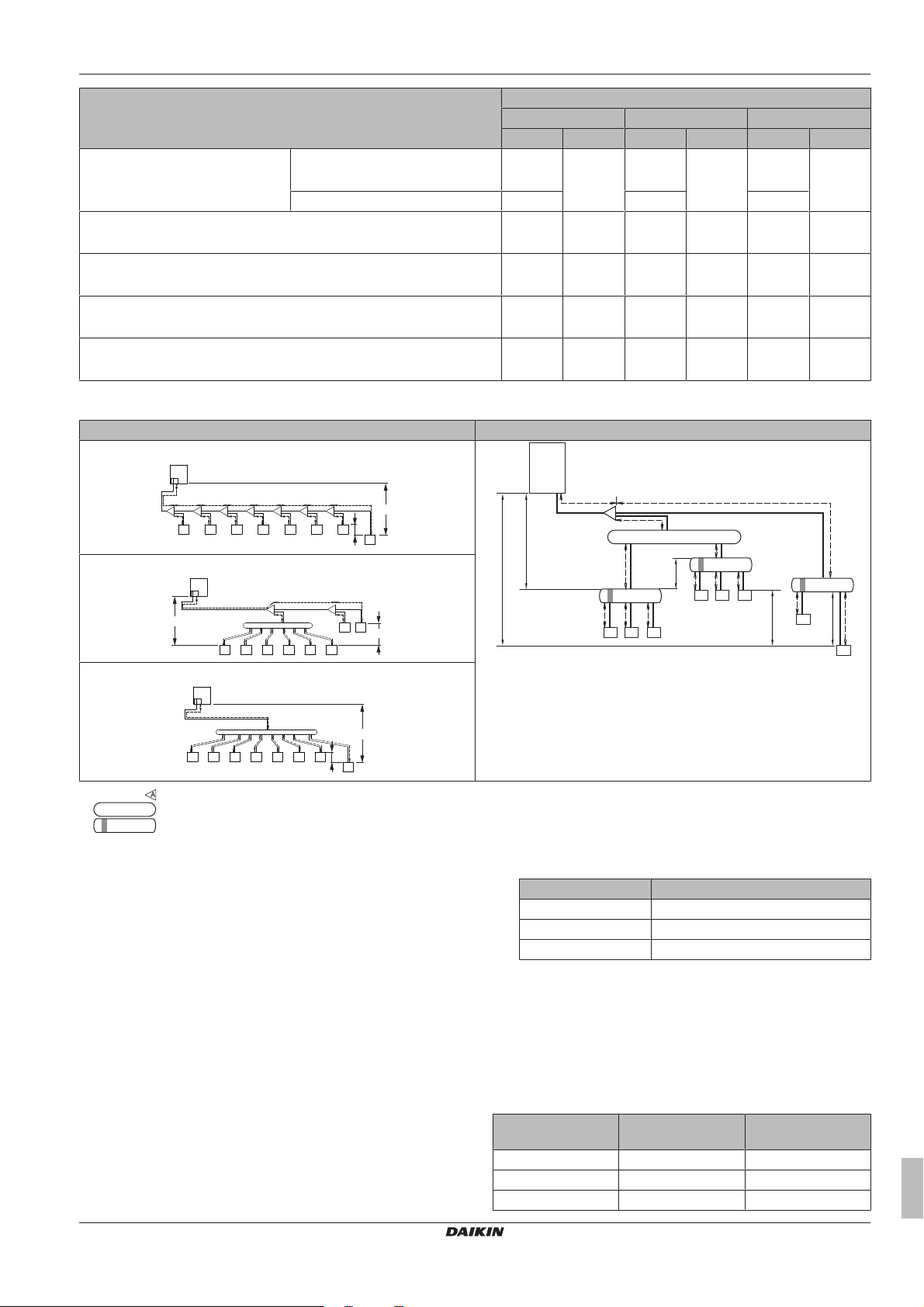
5.3.5 Refrigerant piping length and height difference
The piping lengths and height differences must comply with the following requirements. Two patterns will be discussed:
• Outdoor with 100% VRVDX indoor units
• Outdoor with 100% RADX indoor units
Requirement Limit
Maximum actual piping length
▪ Example 1.1, unit8: a+b+c+d+e+f+g+p≤Limit
▪ Example 1.2, unit6: a+b+h≤Limit
▪ Example 1.2, unit8: a+i+k≤Limit
▪ Example 1.3, unit8: a+i≤Limit
▪ Example 2, unit18: a+b+m≤Limit
Maximum equivalent piping length
Maximum total piping length
▪ Example 1.1: a+b+c+d+e+f+g+h+i+j+k+l+m+n+p≤Limit
▪ Example 2: a+b+c+d+e+f+g+h+i+j+k+l+m≤Limit
Minimum length outdoor-first refrigerant branch kit
▪ Example 2: Limit≤a
Maximum length first branch kit-indoor unit
▪ Example 1.1, unit8: b+c+d+e+f+g+p≤Limit
▪ Example 1.2, unit6: b+h≤Limit
▪ Example 1.2, unit8: i+k≤Limit
▪ Example 1.3, unit8: i≤Limit
▪ Example 2, unit18: b+m≤Limit
Maximum length outdoor-BP
▪ Example 2, BP3: a+b≤Limit
Minimum and maximum length
BP-indoor
▪ Example 2, unit 18: Min.≤m≤Max.
(a)
Indoor unit capacity index<60 N/A 2~15m N/A 2~15m N/A 2~15m
Indoor unit capacity index=60 N/A 2~12m N/A 2~12m N/A 2~12m
Indoor unit capacity index=71 N/A 2~8m N/A 2~8m N/A 2~8m
RXYSQ8 RXYSQ10 RXYSQ12
VRVDX RADX VRVDX RADX VRVDX RADX
100m 80m 120m 80m 120m 80m
130m 100m 150m 100m 150m 100m
300 140m 300m 140m 300m 140m
N/A 5m N/A 5m N/A 5m
40m 40m 40m 40m 40m 40m
N/A 55m N/A 55m N/A 55m
Installer and user reference guide
14
VRV IV-S system air conditioner
RXYSQ8~12TMY1B
4P404225-1A – 2015.11
Requirement Limit
a
A
h i j k l m n
B C D E F G
p
b c d e f
1 2 3 4 5 6 7
8
g
H1
H2
H3
a
c
d
f
H1
BP1
g
h
b
A
l
m
BP3
18
17
131211
H4
e
i
BP2
j
k
161514
H2
H5
a
b
c d e f
i
k
j
g h
A B
1 2 3 4 5 6
7 8
H1
H2
a
c
b d e fig h
1 2 3 4 5 6 7
8
H1
H2
Maximum height difference
outdoor-indoor
Outdoor higher than indoor
▪ Examples: H1≤Limit
Outdoor lower than indoor 40m 40m 40m
Maximum height difference indoor-indoor
▪ Examples: H2≤Limit
Maximum height difference outdoor-BP
▪ Example 2: H3≤Limit
Maximum height difference BP-BP
▪ Example 2: H4≤Limit
Maximum height difference BP-indoor
▪ Example 2: H5≤Limit
(a) Assume equivalent piping length of refnet joint=0.5m and refnet header=1m (for calculation purposes of equivalent piping length, not for
refrigerant charge calculations).
Example 1 (VRVDX indoor units) Example 2 (RADX indoor units)
Example 1.1
5 Preparation
RXYSQ8 RXYSQ10 RXYSQ12
VRVDX RADX VRVDX RADX VRVDX RADX
50m 30m 50m 30m 50m 30m
15m 15m 15m 15m 15m 15m
N/A 30m N/A 30m N/A 30m
N/A 15m N/A 15m N/A 15m
N/A 5m N/A 5m N/A 5m
11~18 RADX indoor units
5.4 Preparing electrical wiring
5.4.1 About electrical compliance
This equipment complies with:
▪ EN/IEC 61000‑3‑12 provided that the short-circuit power Ssc is
greater than or equal to the minimum Ssc value at the interface
point between the user's supply and the public system.
▪ EN/IEC 61000‑3‑12 = European/International Technical
Standard setting the limits for harmonic currents produced by
equipment connected to public low-voltage systems with input
current >16A and ≤75A per phase.
▪ It is the responsibility of the installer or user of the equipment to
ensure, by consultation with the distribution network operator if
necessary, that the equipment is connected only to a supply
with a short-circuit power Ssc greater than or equal to the
minimum Ssc value.
RXYSQ8~12TMY1B
VRV IV-S system air conditioner
4P404225-1A – 2015.11
Example 1.2
Example 1.3
Refnet joint
Refnet header
BP box
1~8 VRVDX indoor units
Model Minimum Ssc value
RXYSQ8 910kVA
RXYSQ10 564kVA
RXYSQ12 615kVA
5.4.2 Safety device requirements
The power supply must be protected with the required safety
devices, i.e. a main switch, a slow blow fuse on each phase and an
earth leakage protector in accordance with the applicable legislation.
Selection and sizing of the wiring should be done in accordance with
the applicable legislation based on the information mentioned in the
table below.
Model Minimum circuit
ampacity
RXYSQ8 18.5A 25A
RXYSQ10 22A 25A
RXYSQ12 24A 32A
Installer and user reference guide
Recommended
fuses
15
6 Installation
2× 3×
8 HP 10+12 HP
For all models:
▪ Phase and frequency: 3N~50Hz
▪ Voltage: 380-415V
▪ Transmission line section:
Transmission wiring Vinyl cords with 0.75 to
Maximum wiring length
(= distance between outdoor
and furthest indoor unit)
Total wiring length
(= distance between outdoor
and all indoors)
If the total transmission wiring exceeds these limits, it may
result in communication error.
1.25mm² sheath or cables
(2‑core wires)
300m
600m
6 Installation
6.1 Overview: Installation
This chapter describes what you have to do and know on-site to
install the system.
Typical workflow
Installation typically consists of the following stages:
▪ Mounting the outdoor unit.
▪ Mounting the indoor units.
▪ Connecting the refrigerant piping.
▪ Checking the refrigerant piping.
▪ Charging refrigerant.
▪ Connecting the electrical wiring.
▪ Finishing the outdoor installation.
▪ Finishing the indoor installation.
6.3 Mounting the outdoor unit
6.3.1 About mounting the outdoor unit
Typical workflow
Mounting the outdoor unit typically consists of the following stages:
1 Providing the installation structure.
2 Installing the outdoor unit.
3 Providing drainage.
4 Preventing the outdoor unit from falling over.
5 Protecting the unit against snow and wind by installing a snow
cover and baffle plates. See "Preparing installation site" in
"5Preparation"on page9.
6.3.2 Precautions when mounting the outdoor unit
INFORMATION
Also read the precautions and requirements in the
following chapters:
▪ General safety precautions
▪ Preparation
INFORMATION
For installation of the indoor unit (mounting the indoor unit,
connecting the refrigerant piping to the indoor unit,
connecting the electrical wiring to the indoor unit …), see
the installation manual of the indoor unit.
6.2 Opening the units
6.2.1 About opening the units
At certain times, you have to open the unit. Example:
▪ When connecting the refrigerant piping
▪ When connecting the electrical wiring
▪ When maintaining or servicing the unit
DANGER: RISK OF ELECTROCUTION
Do NOT leave the unit unattended when the service cover
is removed.
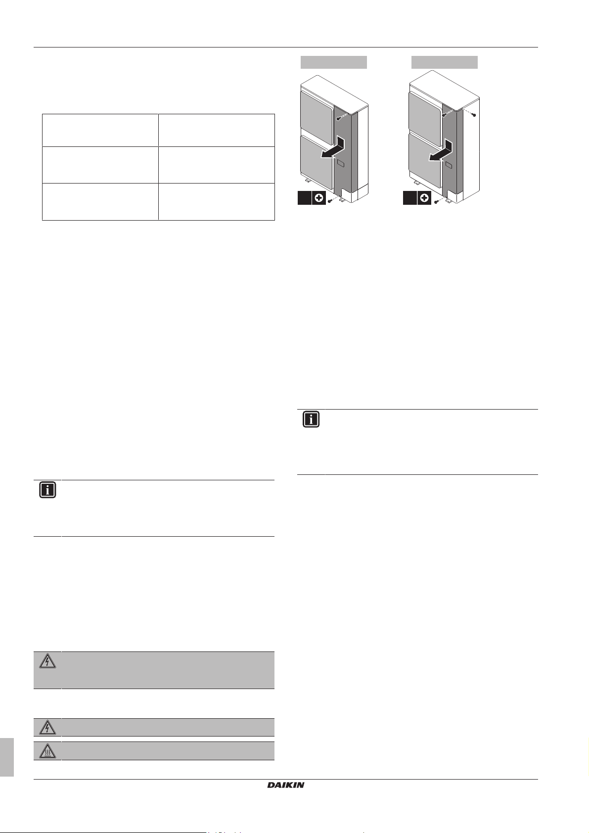
6.2.2 To open the outdoor unit
DANGER: RISK OF ELECTROCUTION
DANGER: RISK OF BURNING
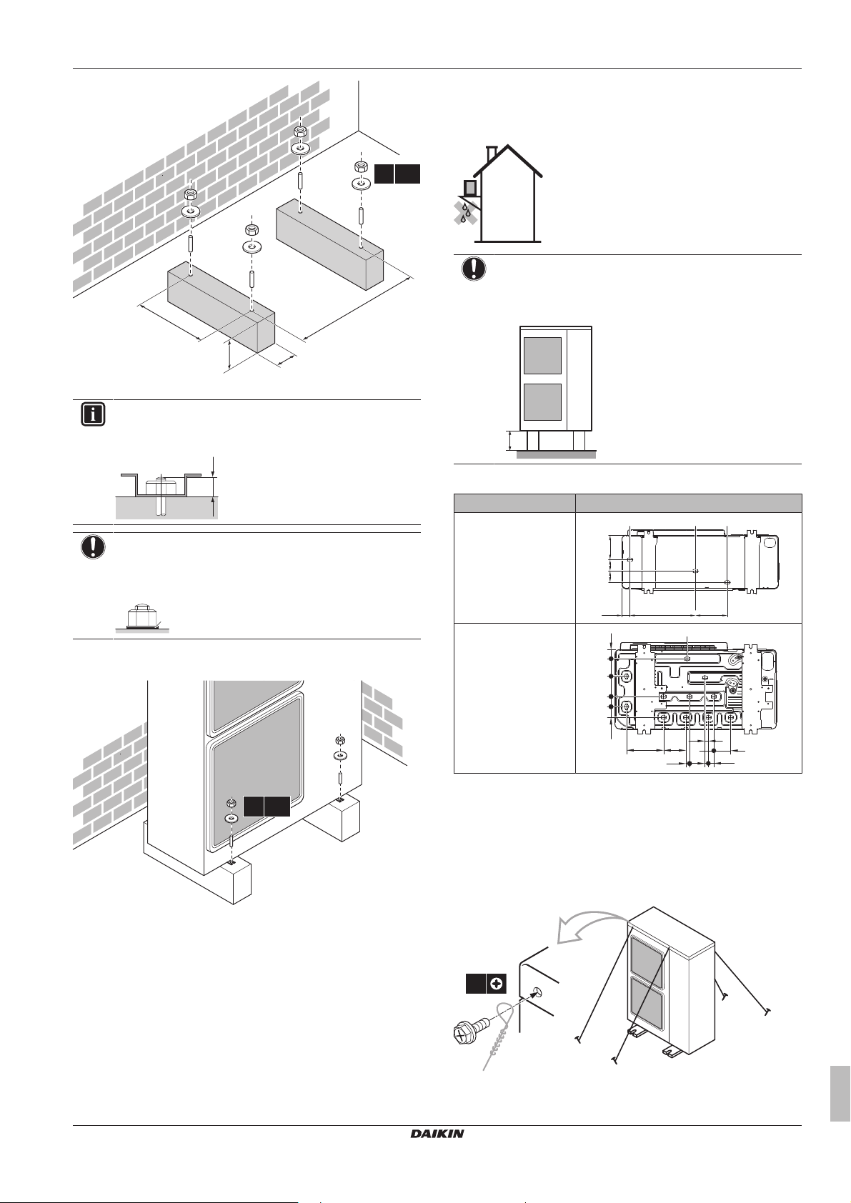
6.3.3 To provide the installation structure
Check the strength and level of the installation ground so that the
unit will not cause any operating vibration or noise.
Fix the unit securely by means of foundation bolts in accordance
with the foundation drawing.
Prepare 4 sets of anchor bolts, nuts and washers (field supply) as
follows:
Installer and user reference guide
16
VRV IV-S system air conditioner
RXYSQ8~12TMY1B
4P404225-1A – 2015.11
(mm)
>150
620
8 HP: 350 (345~355)
10+12 HP: 490 (485~495)
4× M12
a
a Make sure not to cover the drain holes.
20
a
4× M12
≥150 mm
191
6768
395
47
151
a a a
102
118
62
59
216
130
21
20
32
52
98
89
a
4×
INFORMATION
The recommended height of the upper protruding part of
the bolts is 20mm.
6 Installation
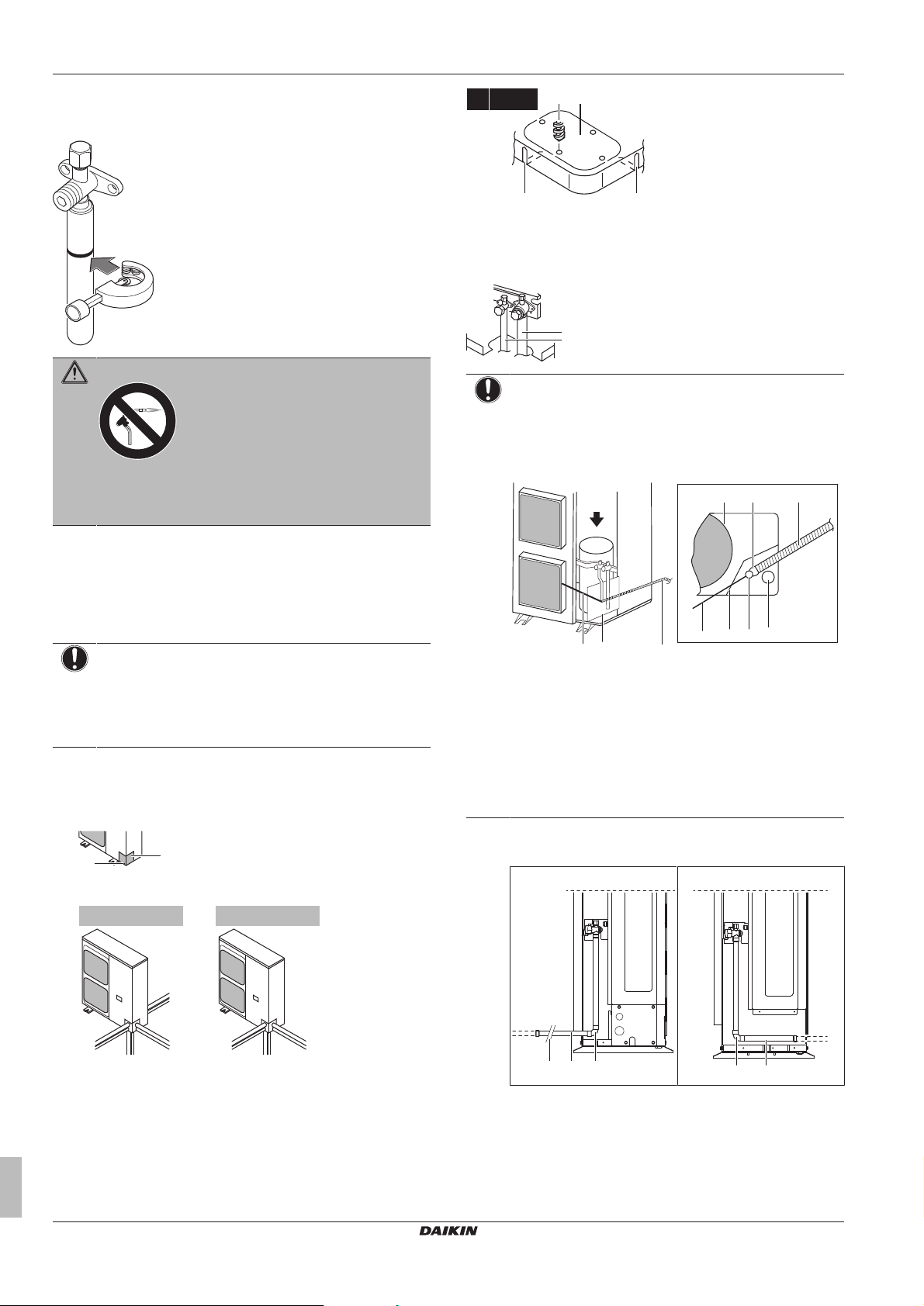
▪ If you install the unit on a frame, install a waterproof plate within
150 mm of the bottom side of the unit in order to prevent the
invasion of water in the unit and to avoid the drain water dripping
(see the following illustration).
NOTICE
If drain holes of the outdoor unit are covered by a mounting
base or by floor surface, raise the unit to provide a free
space of more than 150mm under the outdoor unit.
NOTICE
Fix the outdoor unit to the foundation bolts using nuts with
resin washers (a). If the coating on the fastening area is
stripped off, the nuts rust easily.
6.3.4 To install the outdoor unit
Drain holes (dimensions in mm)
Model Bottom view (mm)
RXYSQ8
RXYSQ10+12
a Drain holes
6.3.6 To prevent the outdoor unit from falling over
In case the unit is installed in places where strong wind can tilt the
unit, take following measure:
Connect cables (field supply) as shown.
6.3.5 To provide drainage
▪ Make sure that condensation water can be evacuated properly.
▪ Install the unit on a base to make sure that there is a proper
drainage in order to avoid ice accumulation.
▪ Prepare a water drainage channel around the foundation to drain
waste water surrounding the unit.
▪ Avoid drain water flowing over the footpath, so that it does not
become slippery in case of ambient freezing temperatures.
RXYSQ8~12TMY1B
VRV IV-S system air conditioner
4P404225-1A – 2015.11
Installer and user reference guide
17
6 Installation
1
1
1
1
2 2
≤Ø25.4 >Ø25.4
a b c d e
f
f
c
d
a
b
a b
cde
6.4 Connecting the refrigerant piping
6.4.1 About connecting the refrigerant piping
Before connecting the refrigerant piping
Make sure the outdoor and indoor units are mounted.
Typical workflow
Connecting the refrigerant piping involves:
▪ Connecting the refrigerant piping to the outdoor unit
▪ Connecting refrigerant branch kits
▪ Connecting the refrigerant piping to the indoor units (see the
installation manual of the indoor units)
▪ Insulating the refrigerant piping
▪ Keeping in mind the guidelines for:
▪ Pipe bending
▪ Brazing
▪ Using the stop valves
▪ Removing pinched pipes
6.4.2 Precautions when connecting the refrigerant piping
INFORMATION
Also read the precautions and requirements in the
following chapters:
▪ General safety precautions
▪ Preparation
DANGER: RISK OF BURNING
NOTICE
Take the following precautions on refrigerant piping into
account:
▪ Avoid anything but the designated refrigerant to get
mixed into the refrigerant cycle (e.g. air).
▪ Only use R410A when adding refrigerant.
▪ Only use installation tools (e.g. manifold gauge set) that
are exclusively used for R410A installations to
withstand the pressure and to prevent foreign materials
(e.g. mineral oils and moisture) from mixing into the
system.
▪ Protect the piping as described in the following table to
prevent dirt, liquid or dust from entering the piping.
▪ Use caution when passing copper tubes through walls.
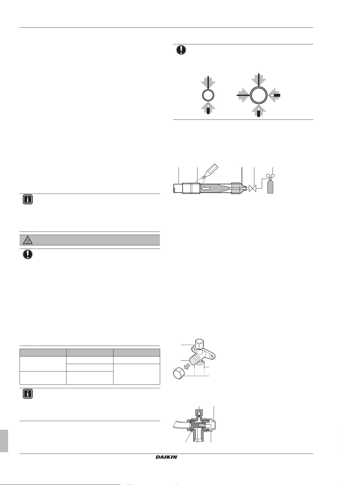
6.4.4 To braze the pipe end
NOTICE
Precautions when connecting field piping. Add brazing
material as shown in the figure.
▪ When brazing, blow through with nitrogen to prevent creation of
large quantities of oxidised film on the inside of the piping. This
film adversely affects valves and compressors in the refrigerating
system and prevents proper operation.
▪ Set the nitrogen pressure to 20kPa (just enough so it can be felt
on the skin) with a pressure-reducing valve.
a Refrigerant piping
b Part to be brazed
c Taping
d Manual valve
e Pressure-reducing valve
f Nitrogen
▪ Do NOT use anti-oxidants when brazing pipe joints.
Residue can clog pipes and break equipment.
▪ Do NOT use flux when brazing copper-to-copper refrigerant
piping. Use phosphor copper brazing filler alloy (BCuP), which
does not require flux.
Flux has an extremely harmful influence on refrigerant piping
systems. For instance, if chlorine based flux is used, it will cause
pipe corrosion or, in particular, if the flux contains fluorine, it will
deteriorate the refrigerant oil.
6.4.5 Using the stop valve and service port
To handle the stop valve
▪ Make sure to keep all stop valves open during operation.
▪ The figure below shows the name of each part required in
handling the stop valve.
▪ The stop valve is factory closed.
Unit Installation period Protection method
Outdoor unit >1month Pinch the pipe
<1month Pinch or tape the pipe
Indoor unit Regardless of the
INFORMATION
Do NOT open the refrigerant stop valve before checking
the refrigerant piping. When you need to charge additional
refrigerant it is recommended to open the refrigerant stop
valve after charging.
period
6.4.3 Pipe bending guidelines
Use a pipe bender for bending. All pipe bends should be as gentle
as possible (bending radius should be 30~40mm or larger).
Installer and user reference guide
18
a Service port and service port cover
b Stop valve
c Field piping connection
d Stop valve cover
RXYSQ8~12TMY1B
VRV IV-S system air conditioner
4P404225-1A – 2015.11
6 Installation
1
2
3
4
c
d
a
b
p<p
>
R410AN2
b c e
a
f g
d
A B
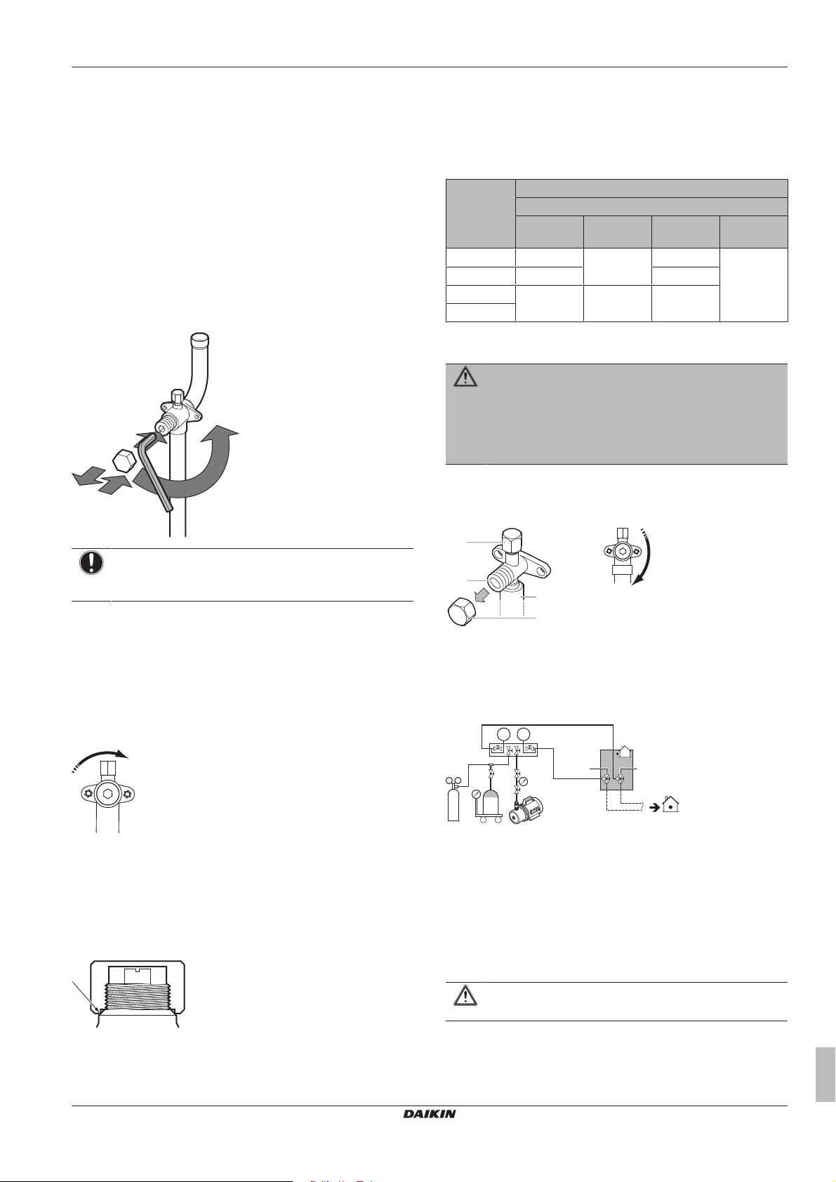
a Service port
b Stop valve cover
c Hexagon hole
d Shaft
e Seal
To open the stop valve
1 Remove the stop valve cover.
2 Insert a hexagon wrench into the stop valve and turn the stop
valve counterclockwise.
3 When the stop valve cannot be turned any further, stop turning.
Result: The valve is now open.
To fully open the Ø19.1~Ø25.4 stop valve, turn the hexagonal
wrench until a torque between 27 and 33N•m is achieved.
Inadequate torque may cause leakage of refrigerant and breakage of
the stop valve cap.
▪ After handling the service port, make sure to tighten the service
port cover securely. For the tightening torque, refer to the table
below.
▪ Check for refrigerant leaks after tightening the service port cover.
Tightening torques
Stop valve
size (mm)
Ø9.5 5.4~6.6 4mm 13.5~16.5 11.5~13.9
Ø12.7 8.1~9.9 18.0~22.0
Ø19.1 27.0~33.0 8mm 22.5~27.5
Ø25.4
Tightening torque N•m (turn clockwise to close)
Shaft
Valve body Hexagonal
wrench
Cap (valve
lid)
Service
port
6.4.6 To remove the pinched pipes
WARNING
Any gas or oil remaining inside the stop valve may blow off
the pinched piping.
Failure to observe the instructions in procedure below
properly may result in property damage or personal injury,
which may be serious depending on the circumstances.
Use the following procedure to remove the pinched piping:
1 Remove the valve cover and make sure that the stop valves are
fully closed.
NOTICE
Pay attention that mentioned torque range is applicable for
opening Ø19.1~Ø25.4mm stop valves only.
To close the stop valve
1 Remove the stop valve cover.
2 Insert a hexagon wrench into the stop valve and turn the stop
valve clockwise.
3 When the stop valve cannot be turned any further, stop turning.
Result: The valve is now closed.
Closing direction:
To handle the stop valve cover
▪ The stop valve cover is sealed where indicated by the arrow. Take
care not to damage it.
▪ After handling the stop valve, make sure to tighten the stop valve
cover securely. For the tightening torque, refer to the table below.
▪ Check for refrigerant leaks after tightening the stop valve cover.
a Service port and service port cover
b Stop valve
c Field piping connection
d Stop valve cover
2 Connect the vacuuming/recovery unit through a manifold to the
service port of all stop valves.
a Pressure reducing valve
b Nitrogen
c Weighing scales
d Refrigerant R410A tank (siphon system)
e Vacuum pump
f Liquid line stop valve
g Gas line stop valve
A Valve A
B Valve B
3 Recover gas and oil from the pinched piping by using a
recovery unit.
To handle the service port
▪ Always use a charge hose equipped with a valve depressor pin,
since the service port is a Schrader type valve.
RXYSQ8~12TMY1B
VRV IV-S system air conditioner
4P404225-1A – 2015.11
CAUTION
Do not vent gases into the atmosphere.
4 When all gas and oil is recovered from the pinched piping,
disconnect the charge hose and close the service ports.
Installer and user reference guide
19
6 Installation
a
b
8 HP
a
b
c
d
10+12 HP
a
b
c
cc
ba
4× Ø6 mm
a
b
a b c
a b f g
cde
A
A
cdd1
dc
5 Cut off the lower part of the gas and liquid stop valve pipes
along the black line. Use an appropriate tool (e.g. a pipe cutter,
a pair of nippers).
WARNING
Never remove the pinched piping by brazing.
Any gas or oil remaining inside the stop valve may blow off
the pinched piping.
6 Wait until all oil is dripped out before continuing with the
connection of the field piping in case the recovery was not
complete.
4 Do the following:
▪ Connect the liquid pipe (a) to the liquid stop valve. (brazing)
▪ Connect the gas pipe (b) to the gas stop valve. (brazing)
NOTICE
When brazing: First braze the liquid side piping, then the
gas side piping. Enter the electrode from the front of the
unit and the welding torch from the right side to braze with
the flames facing outside and avoid the compressor sound
insulation and other piping.
6.4.7 To connect the refrigerant piping to the outdoor unit
NOTICE
Be sure that the field installed piping does not touch other
pipes, the bottom panel or side panel. Especially for the
bottom and side connection, be sure to protect the piping
with suitable insulation, to prevent it from coming into
contact with the casing.
1 Do the following:
▪ Remove the service cover. See "6.2.2To open the outdoor
unit"on page16.
▪ Remove the piping intake plate (a) with screw (b).
2 Choose a piping route (a, b, c or d).
a Electrode
b Burning-resistant plate
c Welding torch
d Flames
e Compressor sound insulation
f Liquid side piping
g Gas side piping
▪ Connect the gas piping accessories (c, d), and cut them to
the required length (d1).
Possibility 1: To the front
Possibility 2: To the back
Installer and user reference guide
20
3 If you have chosen the downwards piping route:
▪ Drill (a, 4×) and remove the knockout hole (b).
▪ Cut out the slits (c) with a metal saw.
VRV IV-S system air conditioner
RXYSQ8~12TMY1B
4P404225-1A – 2015.11
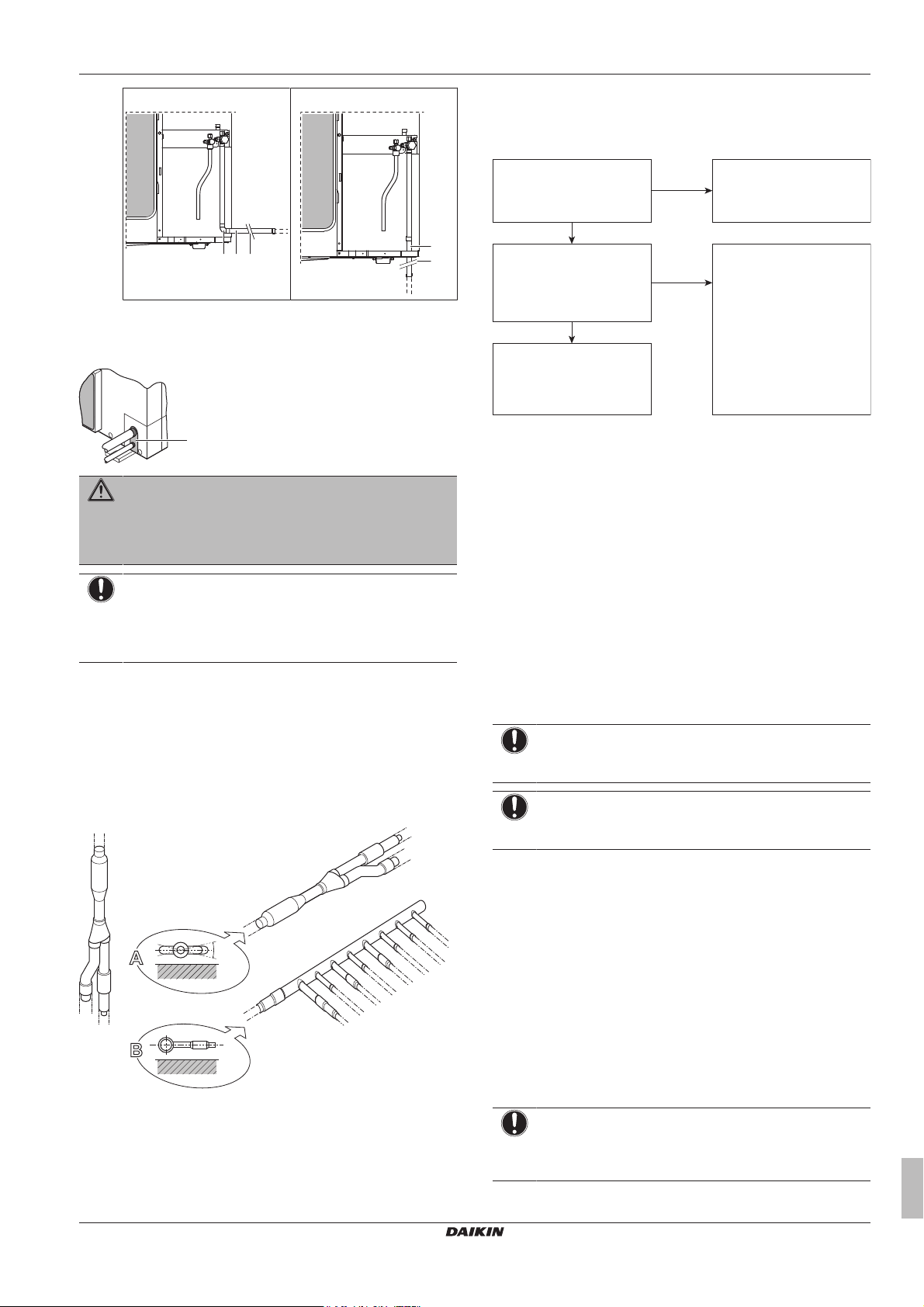
6 Installation
c d d1
d
d1
a
A
B
±
3
0
°
a
b
c
a
Refrigerant piping works are
finished?
The indoor units and/or
outdoor unit were already
powered ON?
Use procedure:
"Method 2: After power ON".
Finish piping work.
Use procedure:
"Method 1: Before power ON
(regular method)".
Yes
No
No
Yes
Possibility 3: To the side
Possibility 4: Downwards
5 Reattach the service cover and the piping intake plate.
6 Seal all gaps (example: a) to prevent snow and small animals
from entering the system.
WARNING
Provide adequate measures to prevent that the unit can be
used as a shelter by small animals. Small animals that
make contact with electrical parts can cause malfunctions,
smoke or fire.
NOTICE
Make sure to open the stop valves after installing the
refrigerant piping and performing vacuum drying. Running
the system with the stop valves closed may break the
compressor.
6.4.8 To connect the refrigerant branching kit
For installation of the refrigerant branching kit, refer to the installation
manual delivered with the kit.
▪ Mount the refnet joint so that it branches either horizontally or
vertically.
▪ Mount the refnet header so that it branches horizontally.
6.5 Checking the refrigerant piping
6.5.1 About checking the refrigerant piping
It is very important that all refrigerant piping work is done before the
units (outdoor or indoor) are powered on.
When the units are powered on, the expansion valves will initialise.
This means that they will close. Leak test and vacuum drying of field
piping and indoor units is impossible when this happens.
Therefore, there will be explained 2 methods for initial installation,
leak test and vacuum drying.
Method 1: Before power ON
If the system has not yet been powered on, no special action is
required to perform the leak test and the vacuum drying.
Method 2: After power ON
If the system has already been powered on, activate setting [2‑21]
(refer to "7.2.4 To access mode 1 or 2" on page30). This setting
will open field expansion valves to guarantee a R410A piping
pathway and make it possible to perform the leak test and the
vacuum drying.
NOTICE
Make sure that all indoor units connected to the outdoor
unit are powered on.
NOTICE
Wait until the outdoor unit has finished the initialisation to
apply setting [2‑21].
RXYSQ8~12TMY1B
VRV IV-S system air conditioner
4P404225-1A – 2015.11
a Horizontal surface
b Refnet joint mounted vertically
c Refnet joint mounted horizontally
Leak test and vacuum drying
Checking the refrigerant piping involves:
▪ Checking for any leakages in the refrigerant piping.
▪ Performing vacuum drying to remove all moisture, air or nitrogen
in the refrigerant piping.
If there is a possibility of moisture being present in the refrigerant
piping (for example, water may have entered the piping), first carry
out the vacuum drying procedure below until all moisture has been
removed.
All piping inside the unit has been factory tested for leaks.
Only field installed refrigerant piping needs to be checked.
Therefore, make sure that all the outdoor unit stop valves are firmly
closed before performing leak test or vacuum drying.
NOTICE
Make sure that all (field supplied) field piping valves are
OPEN (not outdoor unit stop valves!) before you start leak
test and vacuuming.
Installer and user reference guide
21
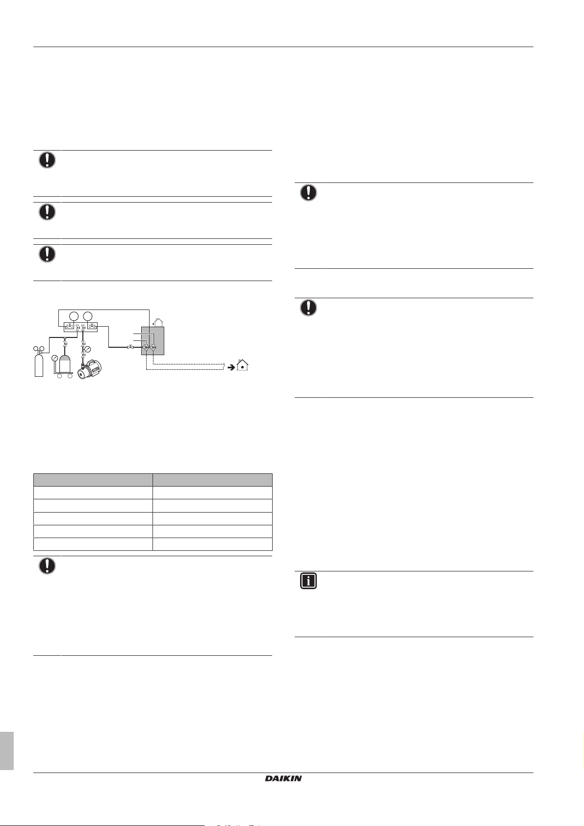
6 Installation
p<p
>
R410AN2
C
b c e
a
g
f
d
A B
For more information on the state of the valves, refer to
"6.5.3Checking refrigerant piping: Setup"on page22.
6.5.2 Checking refrigerant piping: General
Connect the vacuum pump through a manifold to the service port of
all stop valves to increase efficiency (refer to "6.5.3 Checking
refrigerant piping: Setup"on page22).
6.5.3 Checking refrigerant piping: Setup
Valve A Open
Valve B Open
Valve C Open
Liquid line stop valve Close
Gas line stop valve Close
6.5.4 To perform a leak test
The leak test must satisfy the specifications of EN378‑2.
To check for leaks: Vacuum leak test
1 Evacuate the system from the liquid and gas piping to
2 Once reached, turn off the vacuum pump and check that the
Installer and user reference guide
22
guidelines
NOTICE
Use a 2-stage vacuum pump with a non-return valve or a
solenoid valve that can evacuate to a gauge pressure of
–100.7kPa (5Torr absolute).
NOTICE
Make sure the pump oil does not flow oppositely into the
system while the pump is not working.
NOTICE
Do not purge the air with refrigerants. Use a vacuum pump
to evacuate the installation.
a Pressure reducing valve
b Nitrogen
c Weighing scales
d Refrigerant R410A tank (siphon system)
e Vacuum pump
f Liquid line stop valve
g Gas line stop valve
A Valve A
B Valve B
C Valve C
Valve State of valve
NOTICE
The connections to the indoor units and all indoor units
should also be leak and vacuum tested. Keep any possible
(field supplied) field piping valves open as well.
Refer to the indoor unit installation manual for more details.
Leak test and vacuum drying should be done before the
power supply is set to the unit. If not, see also the flow
chart earlier described in this chapter (see "6.5.1 About
checking the refrigerant piping"on page21).
–100.7kPa (–1.007bar/5Torr) for more than 2 hours.
pressure does not rise for at least 1 minute.
3 Should the pressure rise, the system may either contain
moisture (see vacuum drying below) or have leaks.
To check for leaks: Pressure leak test
1 Break the vacuum by pressurising with nitrogen gas to a
minimum gauge pressure of 0.2 MPa (2 bar). Never set the
gauge pressure higher than the maximum operation pressure of
the unit, i.e. 4.0MPa (40bar).
2 Test for leaks by applying a bubble test solution to all piping
connections.
3 Discharge all nitrogen gas.
NOTICE
Make sure to use a recommended bubble test solution
from your wholesaler. Do not use soap water, which may
cause cracking of flare nuts (soap water may contain salt,
which absorbs moisture that will freeze when the piping
gets cold), and/or lead to corrosion of flared joints (soap
water may contain ammonia which causes a corrosive
effect between the brass flare nut and the copper flare).
6.5.5 To perform vacuum drying
NOTICE
The connections to the indoor units and all indoor units
should also be leak and vacuum tested. Keep, if existing,
all (field supplied) field valves to the indoor units open as
well.
Leak test and vacuum drying should be done before the
power supply is set to the unit. If not, see "6.5.1 About
checking the refrigerant piping" on page 21 for more
information.
To remove all moisture from the system, proceed as follows:
1 Evacuate the system for at least 2 hours to a target vacuum of
–100.7kPa (–1.007bar/5Torr).
2 Check that, with the vacuum pump turned off, the target
vacuum is maintained for at least 1 hour.
3 Should you fail to reach the target vacuum within 2 hours or
maintain the vacuum for 1 hour, the system may contain too
much moisture. In that case, break the vacuum by pressurising
with nitrogen gas to a gauge pressure of 0.05 MPa (0.5 bar)
and repeat steps 1 to 3 until all moisture has been removed.
4 Depending on whether you want to immediately charge
refrigerant through the refrigerant charge port or first pre-charge
a portion of refrigerant through the liquid line, either open the
outdoor unit stop valves, or keep them closed. See "6.7.4 To
charge refrigerant"on page24 for more information.
INFORMATION
After opening the stop valve, it is possible that the pressure
in the refrigerant piping does NOT increase. This might be
caused by e.g. the closed state of the expansion valve in
the outdoor unit circuit, but does NOT present any problem
for correct operation of the unit.
6.6 To insulate the refrigerant piping
After finishing the leak test and vacuum drying, the piping must be
insulated. Take into account the following points:
▪ Make sure to insulate the connection piping and refrigerant branch
kits entirely.
▪ Be sure to insulate the liquid and gas piping (for all units).
▪ Use heat resistant polyethylene foam which can withstand a
temperature of 70°C for liquid piping and polyethylene foam which
can withstand a temperature of 120°C for gas piping.
RXYSQ8~12TMY1B
VRV IV-S system air conditioner
4P404225-1A – 2015.11
 Loading...