

Daikin RKS50E3V1B, FDKS50CVMB, RKS60E2V1B, RKS60E3V1B, RKS50F2V1B Service Manual
...
SiBE07-618_C
[Applied Models]
Inverter Pair : Cooling Only
Inverter Pair : Heat Pump
Inverter Pair
Duct Connected Type C-Series

SiBE07-618_C
i Table of Contents
Inverter Pair
Duct Connected Type
C-Series
z
Cooling Only
Indoor Unit
FDKS50CVMB
FDKS60CVMB
Outdoor Unit
RKS50E2(3)V1B RKS50F2V1B RKS50G2V1B
RKS60E2(3)V1B RKS60F2(3)V1B
z
Heat Pump
Indoor Unit
FDXS50CVMB
FDXS60CVMB
Outdoor Unit
RXS50E2(3)V1B RXS50F2V1B RXS50G2V1B
RXS60E2(3)V1B RXS60F2(3)V1B

SiBE07-618_C
Table of Contents ii
1. Introduction .............................................................................................v
1.1 Safety Cautions ........................................................................................v
1.2 Used Icons .............................................................................................. ix
Part 1 List of Functions ................................................................1
1. Functions.................................................................................................2
Part 2 Specifications ....................................................................5
1. Specifications..........................................................................................6
1.1 Cooling Only.............................................................................................6
1.2 Heat Pump ...............................................................................................9
Part 3 Printed Circuit Board Connector Wiring Diagram ...........12
1. Printed Circuit Board Connector Wiring Diagram..................................13
1.1 Indoor Unit..............................................................................................13
1.2 Outdoor Unit ...........................................................................................15
Part 4 Function and Control........................................................17
1. Main Functions......................................................................................18
1.1 Temperature Control ..............................................................................18
1.2 Frequency Principle................................................................................18
1.3 Fan Speed Control for Indoor Units........................................................20
1.4 Program Dry Operation ..........................................................................21
1.5 Automatic Operation...............................................................................22
1.6 Thermostat Control.................................................................................23
1.7 NIGHT SET Mode ..................................................................................24
1.8 HOME LEAVE Operation .......................................................................25
1.9 Inverter POWERFUL Operation .............................................................26
1.10 Other Functions......................................................................................27
2. Function of Thermistor ..........................................................................28
3. Control Specification .............................................................................29
3.1 Mode Hierarchy ......................................................................................29
3.2 Frequency Control..................................................................................30
3.3 Controls at Mode Changing / Start-up....................................................32
3.4 Discharge Pipe Temperature Control.....................................................33
3.5 Input Current Control ..............................................................................34
3.6 Freeze-up Protection Control .................................................................35
3.7 Heating Peak-cut Control .......................................................................35
3.8 Outdoor Fan Control...............................................................................36
3.9 Liquid Compression Protection Function................................................36
3.10 Defrost Control .......................................................................................37
3.11 Electronic Expansion Valve Control .......................................................38
3.12 Malfunctions ...........................................................................................41
3.13 Forced Operation Mode .........................................................................42
Part 5 Operation Manual ............................................................. 43
1. System Configuration............................................................................44
2. Operation Manual..................................................................................45

SiBE07-618_C
iii Table of Contents
2.1 Remote Controller ..................................................................................45
2.2 AUTO · DRY · COOL · HEAT · FAN Operation ......................................46
2.3 POWERFUL Operation ..........................................................................48
2.4 OUTDOOR UNIT QUIET Operation.......................................................49
2.5 HOME LEAVE Operation .......................................................................50
2.6 TIMER Operation ...................................................................................52
Part 6 Service Diagnosis.............................................................54
1. Caution for Diagnosis............................................................................55
1.1 Troubleshooting with LED ......................................................................55
2. Problem Symptoms and Measures.......................................................56
3. Service Check Function ........................................................................57
4. Troubleshooting ....................................................................................60
4.1 Error Codes and Description ..................................................................60
4.2 Indoor Unit PCB Abnormality .................................................................61
4.3 Freeze-up Protection Control or Heating Peak-cut Control....................62
4.4 Fan Motor (AC motor) or Related Abnormality.......................................64
4.5 Thermistor or Related Abnormality (Indoor Unit)....................................65
4.6 Signal Transmission Error (between Indoor Unit and Outdoor Unit)......66
4.7 Unspecified Voltage (between Indoor Unit and Outdoor Unit) ...............67
4.8 Outdoor Unit PCB Abnormality...............................................................68
4.9 OL Activation (Compressor Overload) ...................................................69
4.10 Compressor Lock ...................................................................................70
4.11 DC Fan Lock ..........................................................................................71
4.12 Input Overcurrent Detection ...................................................................72
4.13 Four Way Valve Abnormality..................................................................73
4.14 Discharge Pipe Temperature Control.....................................................75
4.15 High Pressure Control in Cooling ...........................................................76
4.16 Compressor System Sensor Abnormality ..............................................77
4.17 Position Sensor Abnormality ..................................................................78
4.18 CT or Related Abnormality .....................................................................80
4.19 Thermistor or Related Abnormality (Outdoor Unit) .................................82
4.20 Electrical Box Temperature Rise ............................................................84
4.21 Radiation Fin Temperature Rise ............................................................86
4.22 Output Overcurrent Detection ................................................................88
4.23 Refrigerant Shortage ..............................................................................90
4.24 Low-voltage Detection or Over-voltage Detection..................................92
4.25 Signal Transmission Error (on Outdoor Unit PCB).................................93
5. Check ....................................................................................................94
5.1 How to Check .........................................................................................94
Part 7 Removal Procedure ........................................................ 101
1. Outdoor Unit........................................................................................102
1.1 Removal of Outer Panels .....................................................................102
1.2 Removal of Outdoor Fan / Fan Motor...................................................106
1.3 Removal of Electrical Box ....................................................................110
1.4 Removal of PCB...................................................................................115
1.5 Removal of Sound Blanket / Thermistors.............................................118
1.6 Removal of Four Way Valve.................................................................120
1.7 Removal of Electronic Expansion Valve...............................................121

SiBE07-618_C
Table of Contents iv
1.8 Removal of Compressor.......................................................................122
Part 8 Trial Operation and Field Settings.................................125
1. Trial Operation ....................................................................................126
2. Field Settings ......................................................................................127
2.1 When 2 Units are Installed in 1 Room ..................................................127
2.2 Facility Setting Switch (cooling at low outdoor temperature)................128
2.3 Jumper and Switch Settings .................................................................128
3. Application of Silicon Grease to a Power Transistor and
a Diode Bridge ....................................................................................129
Part 9 Appendix.........................................................................130
1. Piping Diagrams..................................................................................131
1.1 Indoor Unit............................................................................................131
1.2 Outdoor Unit .........................................................................................132
2. Wiring Diagrams..................................................................................133
2.1 Indoor Unit............................................................................................133
2.2 Outdoor Unit .........................................................................................134
Introduction SiBE07-618_C
v
1. Introduction
1.1 Safety Cautions
Cautions and
Warnings
Be sure to read the following safety cautions before conducting repair work.
The caution items are classified into “ Warning” and “ Caution”. The “ Warning”
items are especially important since they can lead to death or serious injury if they are not
followed closely. The “ Caution” items can also lead to serious accidents under some
conditions if they are not followed. Therefore, be sure to observe all the safety caution items
described below.
About the pictograms
This symbol indicates the item for which caution must be exercised.
The pictogram shows the item to which attention must be paid.
This symbol indicates the prohibited action.
The prohibited item or action is shown in the illustration or near the symbol.
This symbol indicates the action that must be taken, or the instruction.
The instruction is shown in the illustration or near the symbol.
After the repair work is complete, be sure to conduct a test operation to ensure that the
equipment operates normally, and explain the cautions for operating the product to the
customer.
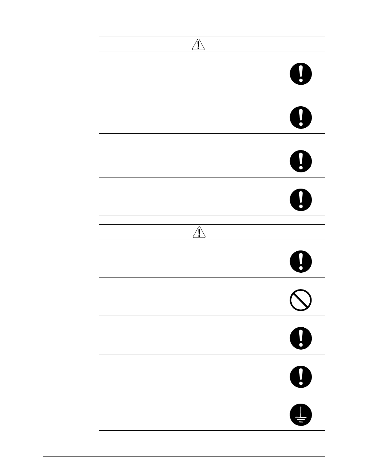
1.1.1 Cautions Regarding Safety of Workers
Warning
Be sure to disconnect the power cable plug from the plug socket before
disassembling the equipment for repair.
Working on the equipment that is connected to the power supply may cause an
electrical shook.
If it is necessary to supply power to the equipment to conduct the repair or
inspecting the circuits, do not touch any electrically charged sections of the
equipment.
If the refrigerant gas is discharged during the repair work, do not touch the
discharged refrigerant gas.
The refrigerant gas may cause frostbite.
When disconnecting the suction or discharge pipe of the compressor at the
welded section, evacuate the refrigerant gas completely at a well-ventilated
place first.
If there is a gas remaining inside the compressor, the refrigerant gas or
refrigerating machine oil discharges when the pipe is disconnected, and it may
cause injury.
If the refrigerant gas leaks during the repair work, ventilate the area. The
refrigerant gas may generate toxic gases when it contacts flames.
The step-up capacitor supplies high-voltage electricity to the electrical
components of the outdoor unit.
Be sure to discharge the capacitor completely before conducting repair work.
A charged capacitor may cause an electrical shock.
Do not start or stop the air conditioner operation by plugging or unplugging the
power cable plug.
Plugging or unplugging the power cable plug to operate the equipment may
cause an electrical shock or fire.
SiBE07-618_C Introduction
vi
Be sure to wear a safety helmet, gloves, and a safety belt when working at a
high place (more than 2 m). Insufficient safety measures may cause a fall
accident.
In case of R-410A refrigerant models, be sure to use pipes, flare nuts and tools
for the exclusive use of the R-410A refrigerant.
The use of materials for R-22 refrigerant models may cause a serious accident
such as a damage of refrigerant cycle as well as an equipment failure.
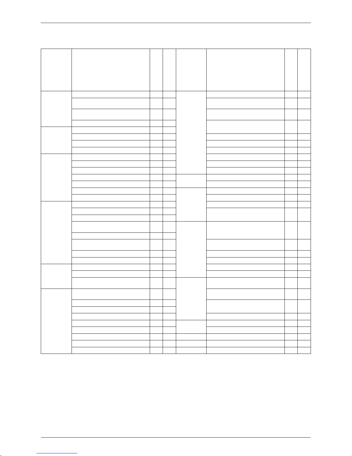
Warning
Caution
Do not repair the electrical components with wet hands.
Working on the equipment with wet hands may cause an electrical shock.
Do not clean the air conditioner by splashing water.
Washing the unit with water may cause an electrical shock.
Be sure to provide the grounding when repairing the equipment in a humid or
wet place, to avoid electrical shocks.
Be sure to turn off the power switch and unplug the power cable when cleaning
the equipment.
The internal fan rotates at a high speed, and cause injury.
Be sure to conduct repair work with appropriate tools.
The use of inappropriate tools may cause injury.
Be sure to check that the refrigerating cycle section has cooled down enough
before conducting repair work.
Working on the unit when the refrigerating cycle section is hot may cause
burns.
Use the welder in a well-ventilated place.
Using the welder in an enclosed room may cause oxygen deficiency.
Introduction SiBE07-618_C
vii
1.1.2 Cautions Regarding Safety of Users
Warning
Be sure to use parts listed in the service parts list of the applicable model and
appropriate tools to conduct repair work. Never attempt to modify the
equipment.
The use of inappropriate parts or tools may cause an electrical shock,
excessive heat generation or fire.
If the power cable and lead wires have scratches or deteriorated, be sure to
replace them.
Damaged cable and wires may cause an electrical shock, excessive heat
generation or fire.
Do not use a joined power cable or extension cable, or share the same power
outlet with other electrical appliances, since it may cause an electrical shock,
excessive heat generation or fire.
Be sure to use an exclusive power circuit for the equipment, and follow the local
technical standards related to the electrical equipment, the internal wiring
regulations, and the instruction manual for installation when conducting
electrical work.
Insufficient power circuit capacity and improper electrical work may cause an
electrical shock or fire.
Be sure to use the specified cable for wiring between the indoor and outdoor
units. Make the connections securely and route the cable properly so that there
is no force pulling the cable at the connection terminals.
Improper connections may cause excessive heat generation or fire.
When wiring between the indoor and outdoor units, make sure that the terminal
cover does not lift off or dismount because of the cable.
If the cover is not mounted properly, the terminal connection section may cause
an electrical shock, excessive heat generation or fire.
Do not damage or modify the power cable.
Damaged or modified power cable may cause an electrical shock or fire.
Placing heavy items on the power cable, and heating or pulling the power cable
may damage the cable.
Do not mix air or gas other than the specified refrigerant (R-410A / R-22) in the
refrigerant system.
If air enters the refrigerating system, an excessively high pressure results,
causing equipment damage and injury.
If the refrigerant gas leaks, be sure to locate the leaking point and repair it
before charging the refrigerant. After charging refrigerant, make sure that there
is no refrigerant leak.
If the leaking point cannot be located and the repair work must be stopped, be
sure to perform pump-down and close the service valve, to prevent the
refrigerant gas from leaking into the room. The refrigerant gas itself is
harmless, but it may generate toxic gases when it contacts flames, such as fan
and other heaters, stoves and ranges.
When relocating the equipment, make sure that the new installation site has
sufficient strength to withstand the weight of the equipment.
If the installation site does not have sufficient strength and if the installation
work is not conducted securely, the equipment may fall and cause injury.
SiBE07-618_C Introduction
viii
Check to make sure that the power cable plug is not dirty or loose, then insert
the plug into a power outlet securely.
If the plug has dust or loose connection, it may cause an electrical shock or fire.
Be sure to install the product correctly by using the provided standard
installation frame.
Incorrect use of the installation frame and improper installation may cause the
equipment to fall, resulting in injury.
For unitary type
only
Be sure to install the product securely in the installation frame mounted on the
window frame.
If the unit is not securely mounted, it may fall and cause injury.
For unitary type
only
When replacing the coin battery in the remote controller, be sure to disposed
of the old battery to prevent children from swallowing it.
If a child swallows the coin battery, see a doctor immediately.
Warning
Caution
Installation of a leakage breaker is necessary in some cases depending on the
conditions of the installation site, to prevent electrical shocks.
Do not install the equipment in a place where there is a possibility of
combustible gas leaks.
If the combustible gas leaks and remains around the unit, it may cause a fire.
Check to see if the parts and wires are mounted and connected properly, and
if the connections at the soldered or crimped terminals are secure.
Improper installation and connections may cause excessive heat generation,
fire or an electrical shock.
If the installation platform or frame has corroded, replace it.
Corroded installation platform or frame may cause the unit to fall, resulting in
injury.
Check the grounding, and repair it if the equipment is not properly grounded.
Improper grounding may cause an electrical shock.

Introduction SiBE07-618_C
ix
1.2 Used Icons
Icons are used to attract the attention of the reader to specific information. The meaning of each
icon is described in the table below:
Be sure to measure the insulation resistance after the repair, and make sure
that the resistance is 1 MΩ or higher.
Faulty insulation may cause an electrical shock.
Be sure to check the drainage of the indoor unit after the repair.
Faulty drainage may cause the water to enter the room and wet the furniture
and floor.
Do not tilt the unit when removing it.
The water inside the unit may spill and wet the furniture and floor.
Be sure to install the packing and seal on the installation frame properly.
If the packing and seal are not installed properly, water may enter the room and
wet the furniture and floor.
For unitary type
only
Caution
Icon Type of
Information
Description
Note:
Note A “note” provides information that is not indispensable, but may
nevertheless be valuable to the reader, such as tips and tricks.
Caution
Caution A “caution” is used when there is danger that the reader, through
incorrect manipulation, may damage equipment, loose data, get
an unexpected result or has to restart (part of) a procedure.
Warning
Warning A “warning” is used when there is danger of personal injury.
Reference A “reference” guides the reader to other places in this binder or
in this manual, where he/she will find additional information on a
specific topic.

SiBE07-618_C
List of Functions 1
Part 1
List of Functions
1. Functions.................................................................................................2
Functions SiBE07-618_C
2 List of Functions
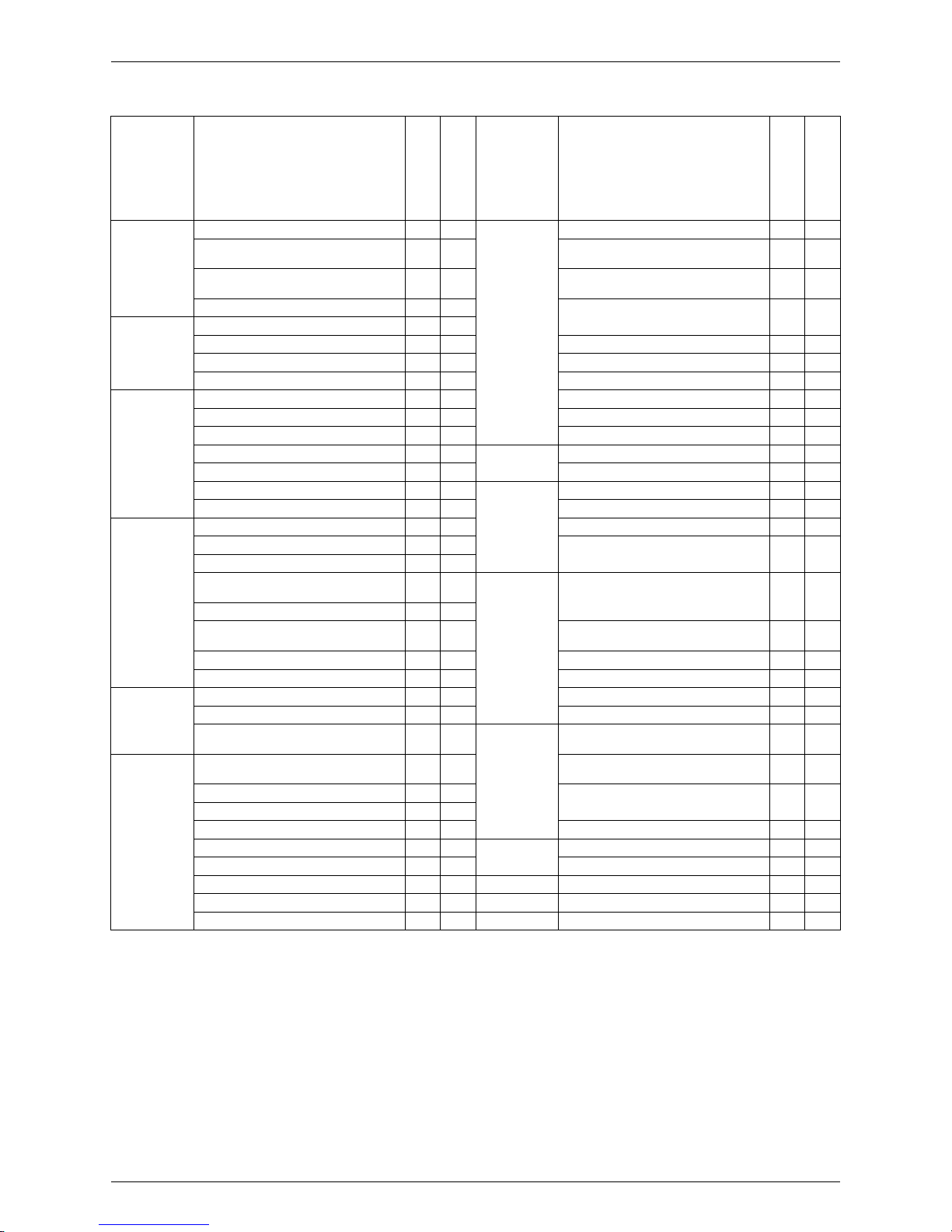
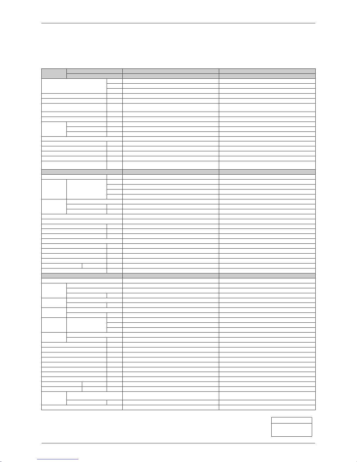
1. Functions
Category Functions
FDKS50/60CVMB
RKS50/60E2(3)V1B
FDXS50/60CVMB
RXS50/60E2(3)V1B
Category Functions
FDKS50/60CVMB
RKS50/60E2(3)V1B
FDXS50/60CVMB
RXS50/60E2(3)V1B
Basic
Function
Inverter (with Inverter Power Control)
{{
Health &
Clean
Air-Purifying Filter — —
Operation Limit for Cooling (°CDB)
–10
~46
★
–10
~46
Photocatalytic Deodorizing Filter — —
Operation Limit for Heating (°CWB) —
–15
~18
Air-Purifying Filter with Photocatalytic
Deodorizing Function
——
PAM Control
{{
Titanium Apatite Photocatalytic
Air-Purifying Filter
——
Compressor Oval Scroll Compressor — —
Swing Compressor
{{
Air Filter (Prefilter)
{{
Rotary Compressor — — Wipe-Clean Flat Panel — —
Reluctance DC Motor
{{
Washable Grille — —
Comfortable
Airflow
Power-Airflow Flap — — Mold Proof Operation — —
Power-Airflow Dual Flaps — — Heating Dry Operation — —
Power-Airflow Diffuser — — Good-Sleep Cooling Operation — —
Wide-Angle Louvers — — Timer 24-Hour ON/OFF TIMER
{{
Vertical Auto-Swing (Up and Down) — — NIGHT SET Mode
{{
Horizontal Auto-Swing (Right and Left) — — Worry Free
“Reliability &
Durability”
Auto-Restart (after Power Failure)
{{
3-D Airflow — — Self-Diagnosis (Digital, LED) Display
{{
Comfort
Control
Auto Fan Speed
{{
Wiring Error Check — —
Indoor Unit Quiet Operation
{{
Anti-Corrosion Treatment of Outdoor
Heat Exchanger
{{
NIGHT QUIET Mode (Automatic) — —
OUTDOOR UNIT QUIET Operation
(Manual)
{{
Flexibility
Multi-Split / Split Type Compatible
Indoor Unit
{{
INTELLIGENT EYE Operation — —
Quick Warming Function
(Preheating Operation)
—
{
Flexible Voltage Correspondence — —
Hot-Start Function —
{
High Ceiling Application — —
Automatic Defrosting —
{
Chargeless 10 m 10 m
Operation Automatic Operation —
{
Either Side Drain (Right or Left) — —
Program Dry Operation
{{
Power Selection — —
Fan Only
{{
Remote
Control
5-Rooms Centralized Controller
(Option)
{{
Lifestyle
Convenience
New POWERFUL Operation
(Non-Inverter)
——
Remote Control Adaptor
(Normal Open Pulse Contact) (Option)
{{
Inverter POWERFUL Operation
{{
Remote Control Adaptor
(Normal Open Contact) (Option)
{{
Priority-Room Setting — —
COOL / HEAT Mode Lock — — DIII-NET Compatible (Adaptor) (Option)
{{
HOME LEAVE Operation
{{
Remote
Controller
Wireless
{{
ECONO Operation — — Wired (Option)
{{
Indoor Unit ON/OFF Button
{{
Signal Receiving Sign
{{
Temperature Display — —
Note:
{
: Holding Functions
— : No Functions
★
: Lower limit can be extended to –15°C by turning
switch. (facility use only)
SiBE07-618_C Functions
List of Functions 3
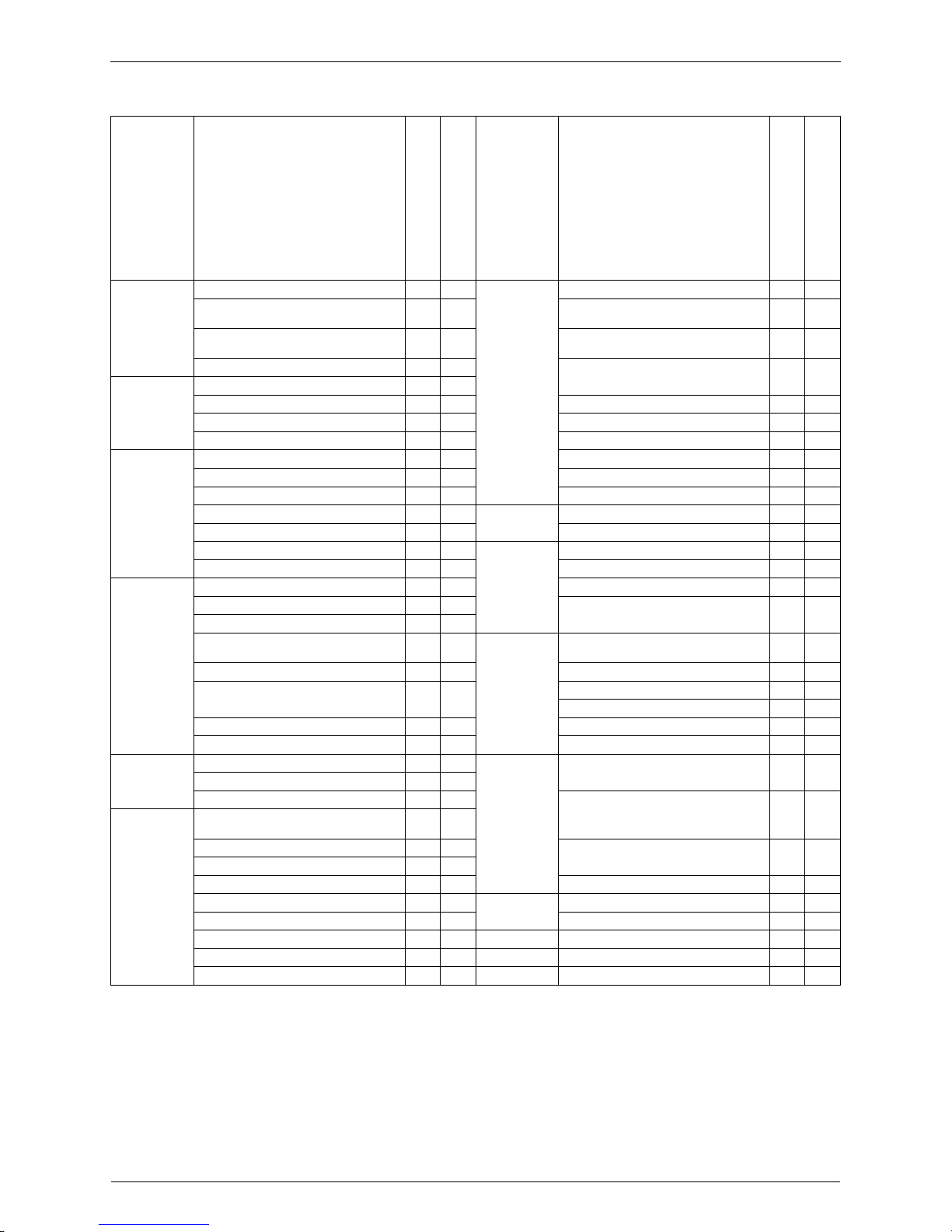
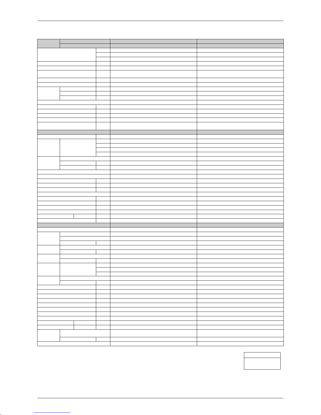
Category Functions
FDKS50/60CVMB
RKS50/60F2V1B
FDXS50/60CVMB
RXS50/60F2V1B
Category Functions
FDKS50/60CVMB
RKS50/60F2V1B
FDXS50/60CVMB
RXS50/60F2V1B
Basic
Function
Inverter (with Inverter Power Control)
{{
Health &
Clean
Air-Purifying Filter — —
Operation Limit for Cooling (°CDB)
–10
~46
★
–10
~46
Photocatalytic Deodorizing Filter — —
Operation Limit for Heating (°CWB) —
–15
~18
Air-Purifying Filter with Photocatalytic
Deodorizing Function
——
PAM Control
{{
Titanium Apatite Photocatalytic
Air-Purifying Filter
——
Compressor Oval Scroll Compressor — —
Swing Compressor
{{
Air Filter (Prefilter)
{{
Rotary Compressor — — Wipe-Clean Flat Panel — —
Reluctance DC Motor
{{
Washable Grille — —
Comfortable
Airflow
Power-Airflow Flap — — Mold Proof Operation — —
Power-Airflow Dual Flaps — — Heating Dry Operation — —
Power-Airflow Diffuser — — Good-Sleep Cooling Operation — —
Wide-Angle Louvers — — Timer 24-Hour ON/OFF TIMER
{{
Vertical Auto-Swing (Up and Down) — — NIGHT SET Mode
{{
Horizontal Auto-Swing (Right and Left) — — Worry Free
“Reliability &
Durability”
Auto-Restart (after Power Failure)
{{
3-D Airflow — — Self-Diagnosis (Digital, LED) Display
{{
Comfort
Control
Auto Fan Speed
{{
Wiring Error Check — —
Indoor Unit Quiet Operation
{{
Anti-Corrosion Treatment of Outdoor
Heat Exchanger
{{
NIGHT QUIET Mode (Automatic) — —
OUTDOOR UNIT QUIET Operation
(Manual)
{{
Flexibility
Multi-Split / Split Type Compatible
Indoor Unit
{{
INTELLIGENT EYE Operation — —
Quick Warming Function
(Preheating Operation)
—
{
Flexible Voltage Correspondence — —
Hot-Start Function —
{
High Ceiling Application — —
Automatic Defrosting —
{
Chargeless 10 m 10 m
Operation Automatic Operation —
{
Either Side Drain (Right or Left) — —
Program Dry Operation
{{
Power Selection — —
Fan Only
{{
Remote
Control
5-Rooms Centralized Controller
(Option)
{{
Lifestyle
Convenience
New POWERFUL Operation
(Non-Inverter)
——
Remote Control Adaptor
(Normal Open Pulse Contact) (Option)
{{
Inverter POWERFUL Operation
{{
Remote Control Adaptor
(Normal Open Contact) (Option)
{{
Priority-Room Setting — —
COOL / HEAT Mode Lock — — DIII-NET Compatible (Adaptor) (Option)
{{
HOME LEAVE Operation
{{
Remote
Controller
Wireless
{{
ECONO Operation — — Wired (Option)
{{
Indoor Unit ON/OFF Button
{{
Signal Receiving Sign
{{
Temperature Display — —
Note:
{
: Holding Functions
— : No Functions
★
: Lower limit can be extended to –15°C by turning
switch. (facility use only)
Functions SiBE07-618_C
4 List of Functions
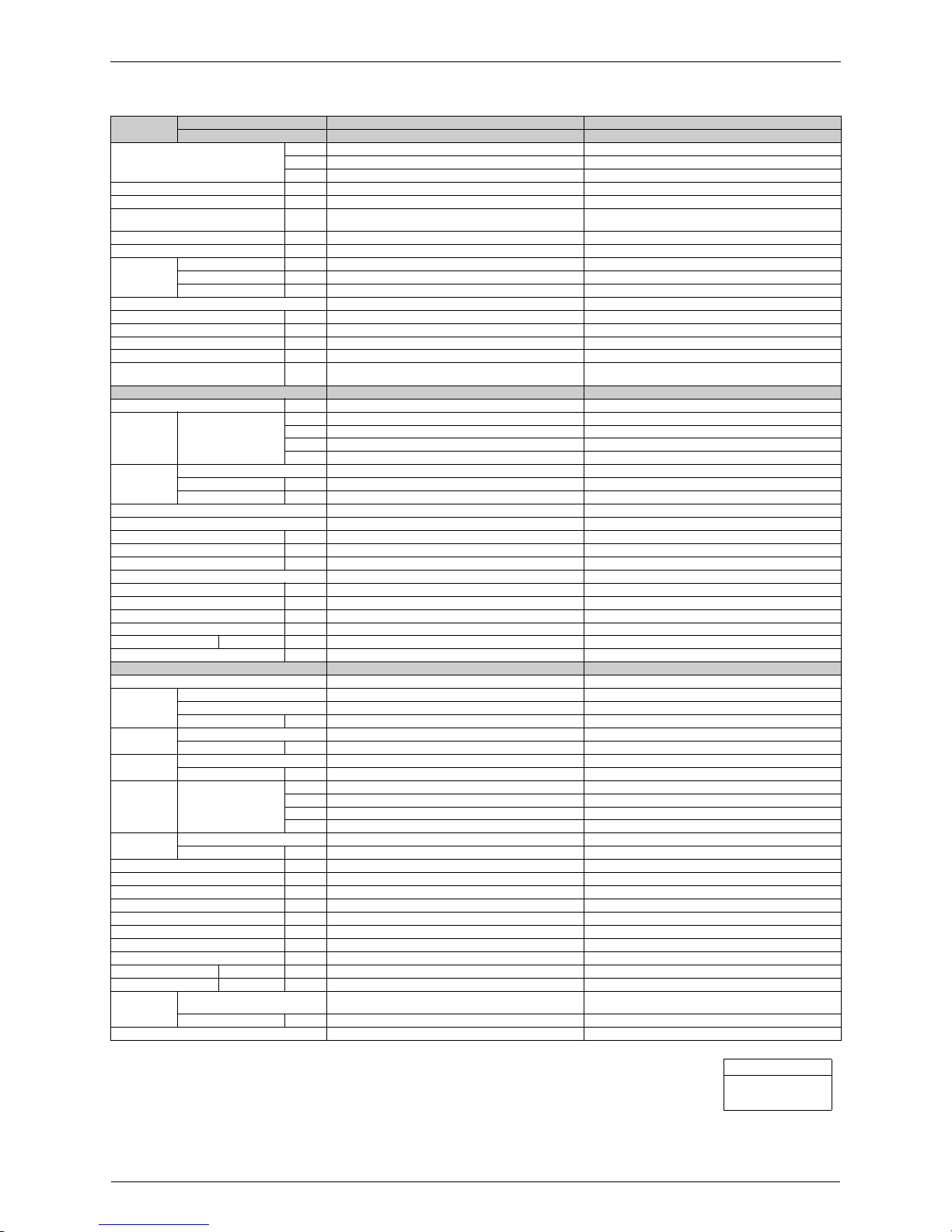
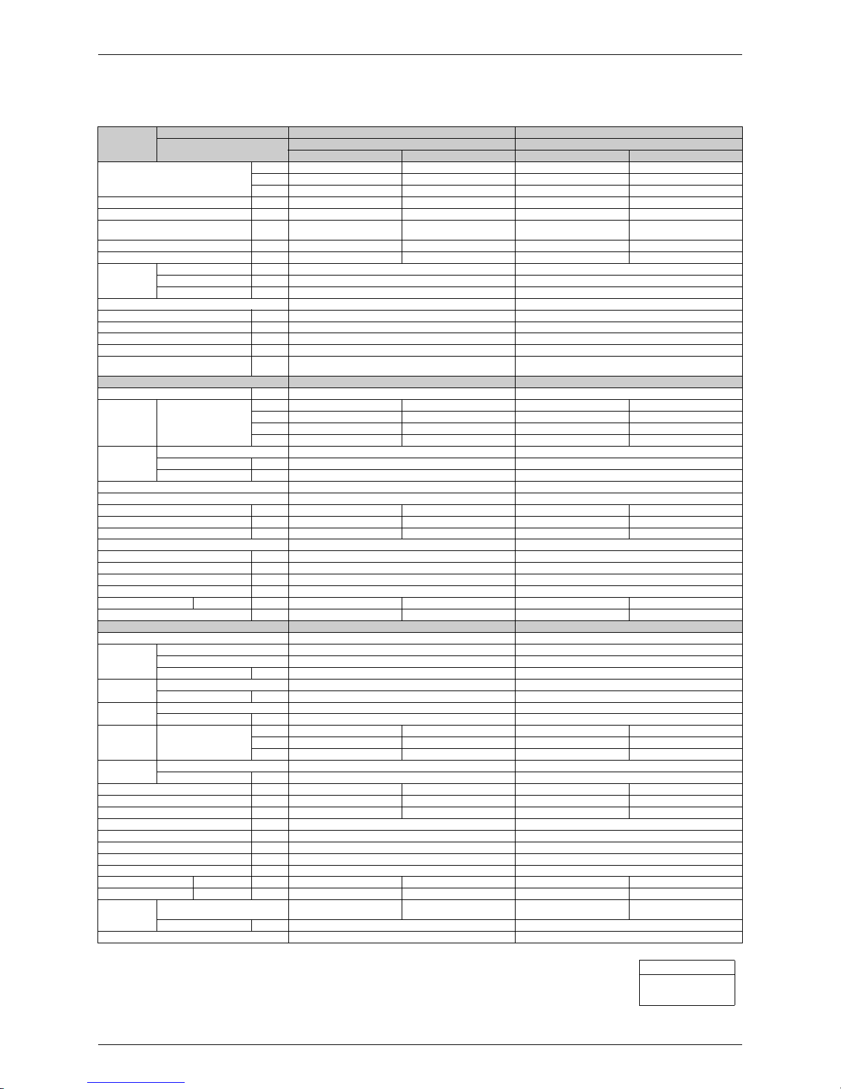
Category Functions
FDKS50/60CVMB
RKS50G2V1B, RKS60F3V1B
FDXS50/60CVMB
RXS50G2V1B, RXS60F3V1B
Category Functions
FDKS50/60CVMB
RKS50G2V1B, RKS60F3V1B
FDXS50/60CVMB
RXS50G2V1B, RXS60F3V1B
Basic
Function
Inverter (with Inverter Power Control)
{{
Health &
Clean
Air-Purifying Filter — —
Operation Limit for Cooling (°CDB)
–10
~46
★
–
10
~46
Photocatalytic Deodorizing Filter — —
Operation Limit for Heating (°CWB) —
–15
~18
Air-Purifying Filter with Photocatalytic
Deodorizing Function
——
PAM Control
{{
Titanium Apatite Photocatalytic
Air-Purifying Filter
——
Compressor Oval Scroll Compressor — —
Swing Compressor
{{
Air Filter (Prefilter)
{{
Rotary Compressor — — Wipe-Clean Flat Panel — —
Reluctance DC Motor
{{
Washable Grille — —
Comfortable
Airflow
Power-Airflow Flap — — Mold Proof Operation — —
Power-Airflow Dual Flaps — — Heating Dry Operation — —
Power-Airflow Diffuser — — Good-Sleep Cooling Operation — —
Wide-Angle Louvers — — Timer 24-Hour ON/OFF TIMER
{{
Vertical Auto-Swing (Up and Down) — — NIGHT SET Mode
{{
Horizontal Auto-Swing (Right and Left) — — Worry Free
“Reliability &
Durability”
Auto-Restart (after Power Failure)
{{
3-D Airflow — — Self-Diagnosis (Digital, LED) Display
{{
Comfort
Control
Auto Fan Speed
{{
Wiring Error Check — —
Indoor Unit Quiet Operation
{{
Anti-Corrosion Treatment of Outdoor
Heat Exchanger
{{
NIGHT QUIET Mode (Automatic) — —
OUTDOOR UNIT QUIET Operation
(Manual)
{{
Flexibility Multi-Split / Split Type Compatible
Indoor Unit
{{
INTELLIGENT EYE Operation — — Flexible Voltage Correspondence — —
Quick Warming Function
(Preheating Operation)
—
{
High Ceiling Application — —
Chargeless 10 m 10 m
Hot-Start Function —
{
Either Side Drain (Right or Left) — —
Automatic Defrosting —
{
Power Selection — —
Operation Automatic Operation —
{
Remote
Control
5-Rooms Centralized Controller
(Option)
{{
Program Dry Operation
{{
Fan Only
{{
Remote Control Adaptor
(Normal Open Pulse Contact) (Option)
{{
Lifestyle
Convenience
New POWERFUL Operation
(Non-Inverter)
——
Inverter POWERFUL Operation
{{
Remote Control Adaptor
(Normal Open Contact) (Option)
{{
Priority-Room Setting — —
COOL / HEAT Mode Lock — — DIII-NET Compatible (Adaptor) (Option)
{{
HOME LEAVE Operation
{{
Remote
Controller
Wireless
{{
ECONO Operation — — Wired (Option)
{{
Indoor Unit ON/OFF Button
{{
Signal Receiving Sign
{{
Temperature Display — —
Note:
{
: Holding Functions
— : No Functions
★
: Lower limit can be extended to –15°C by turning
switch. (facility use only)

SiBE07-618_C
Specifications 5
Part 2
Specifications
1. Specifications..........................................................................................6
1.1 Cooling Only.............................................................................................6
1.2 Heat Pump ...............................................................................................9
Specifications SiBE07-618_C
6 Specifications
1. Specifications
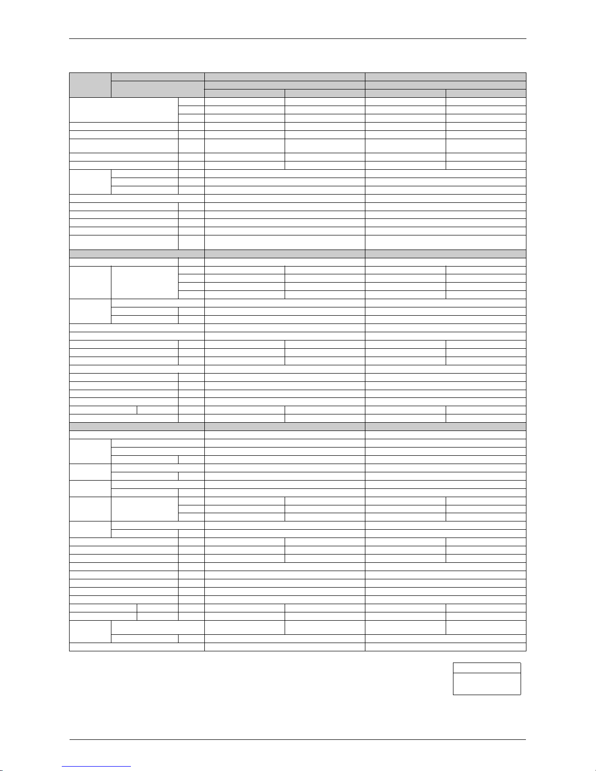
1.1 Cooling Only
50 Hz, 230 V
Models
Indoor Units FDKS50CVMB FDKS60CVMB
Outdoor Units RKS50E2(3)V1B RKS60E2(3)V1B
Capacity
Rated (Min. ~ Max.)
kW 5.0 (2.0 ~ 5.3) 6.0 (2.0 ~ 6.5)
Btu/h 17,100 (6,800 ~ 18,100) 20,500 (6,800 ~ 22,200)
kcal/h 4,300 (1,720 ~ 4,560) 5,160 (1,720 ~ 5,590)
Moisture Removal L/h 2.9 3.9
Running Current (Rated) A 7.3 9.4
Power Consumption
Rated (Min. ~ Max.)
W 1,650 (500 ~ 1,930) 2,130 (500 ~ 2,490)
Power Factor % 98.3 98.5
COP Rated (Min. ~ Max.) W/W 3.03 (4.00 ~ 2.75) 2.82 (4.00 ~ 2.61)
Piping
Connections
Liquid mm
φ
6.4
φ
6.4
Gas mm
φ
12.7
φ
12.7
Drain mm VP20 (O.D.
φ
26 / I.D. φ 20) VP20 (O.D. φ 26 / I.D. φ 20)
Heat Insulation Both Liquid and Gas Pipes Both Liquid and Gas Pipes
Max. Interunit Piping Length m 30 30
Min. Interunit Piping Length m 1.5 1.5
Max. Interunit Height Difference m 20 20
Chargeless m 10 10
Amount of Additional Charge
of Refrigerant
g/m 20 20
Indoor Units FDKS50CVMB FDKS60CVMB
External Static Pressure Pa 40 40
Airflow Rate
m³/min
(cfm)
H 12.0 (424) 16.0 (565)
M 11.0 (388) 14.8 (523)
L 10.0 (353) 13.5 (477)
SL 8.4 (297) 11.2 (395)
Fan
Type Sirocco Fan Sirocco Fan
Motor Output W 130 130
Speed Steps 5 Steps, Quiet, Auto 5 Steps, Quiet, Auto
Air Direction Control – –
Air Filter Removable / Washable / Mildew Proof Removable / Washable / Mildew Proof
Running Current (Rated) A 0.64 0.74
Power Consumption (Rated) W 140 160
Power Factor % 95.1 94.0
Temperature Control Microcomputer Control Microcomputer Control
Dimensions (H × W × D) mm 200 × 900 × 620 200 × 1,100 × 620
Packaged Dimensions (H × W × D) mm 266 × 1,106 × 751 266 × 1,306 × 751
Weight kg 27 30
Gross Weight kg 34 37
Operation Sound H / M / L / SL dBA 37 / 35 / 33 / 31 38 / 36 / 34 / 32
Sound Power dBA 55 56
Outdoor Units RKS50E2(3)V1B RKS60E2(3)V1B
Casing Color Ivory White Ivory White
Compressor
Type Hermetically Sealed Swing Type Hermetically Sealed Swing Type
Model 2YC36BXD 2YC36BXD
Motor Output W 1,100 1,100
Refrigerant
Oil
Type FVC50K FVC50K
Charge L 0.65 0.65
Refrigerant
Type R-410A R-410A
Charge kg 1.50 1.50
Airflow Rate
m³/min
(cfm)
HH 50.9 (1,798) 54.2 (1,914)
H 48.9 (1,727) 50.9 (1,798)
L 41.7 (1,473) 45.0 (1,589)
Fan
Type Propeller Propeller
Motor Output W 53 53
Running Current (Rated) A 6.66 8.66
Power Consumption (Rated) W 1,510 1,970
Power Factor % 98.6 98.9
Starting Current A 7.3 9.4
Dimensions (H × W × D) mm 735 × 825 × 300 735 × 825 × 300
Packaged Dimensions (H × W × D) mm 797 × 960 × 390 797 × 960 × 390
Weight kg 47 47
Gross Weight kg 52 52
Operation Sound H / L dBA 47 / 44 49 / 46
Sound Power H dBA 61 63
Conditions
Temperature
Indoor ; 27°CDB / 19°CWB
Outdoor ; 35°CDB / 24°CWB
Indoor ; 27°CDB / 19°CWB
Outdoor ; 35°CDB / 24°CWB
Piping Length m 7.5 7.5
Drawing No. 3D052134A 3D052135
Conversion Formulae
kcal/h = kW × 860
Btu/h = kW × 3412
cfm = m³/min × 35.3
SiBE07-618_C Specifications
Specifications 7
50 Hz, 230 V
Models
Indoor Units FDKS50CVMB FDKS60CVMB
Outdoor Units RKS50F2V1B RKS60F2V1B
Capacity
Rated (Min. ~ Max.)
kW 5.0 (1.7 ~ 5.3) 6.0 (1.7 ~ 6.5)
Btu/h 17,100 (5,800 ~ 18,100) 20,500 (5,800 ~ 22,200)
kcal/h 4,300 (1,460 ~ 4,560) 5,160 (1,460 ~ 5,590)
Moisture Removal L/h 2.9 3.9
Running Current (Rated) A 7.3 9.4
Power Consumption
Rated (Min. ~ Max.)
W 1,650 (440 ~ 1,930) 2,130 (440 ~ 2,490)
Power Factor % 98.3 98.5
COP Rated (Min. ~ Max.) W/W 3.03 (3.86 ~ 2.75) 2.82 (3.86 ~ 2.61)
Piping
Connections
Liquid mm
φ
6.4
φ
6.4
Gas mm
φ
12.7
φ
12.7
Drain mm VP20 (O.D.
φ
26 / I.D. φ 20) VP20 (O.D. φ 26 / I.D. φ 20)
Heat Insulation Both Liquid and Gas Pipes Both Liquid and Gas Pipes
Max. Interunit Piping Length m 30 30
Min. Interunit Piping Length m 1.5 1.5
Max. Interunit Height Difference m 20 20
Chargeless m 10 10
Amount of Additional Charge
of Refrigerant
g/m 20 20
Indoor Units FDKS50CVMB FDKS60CVMB
External Static Pressure Pa 40 40
Airflow Rate
m³/min
(cfm)
H 12.0 (424) 16.0 (565)
M 11.0 (388) 14.8 (523)
L 10.0 (353) 13.5 (477)
SL 8.4 (297) 11.2 (395)
Fan
Type Sirocco Fan Sirocco Fan
Motor Output W 130 130
Speed Steps 5 Steps, Quiet, Auto 5 Steps, Quiet, Auto
Air Direction Control – –
Air Filter Removable / Washable / Mildew Proof Removable / Washable / Mildew Proof
Running Current (Rated) A 0.64 0.74
Power Consumption (Rated) W 140 160
Power Factor % 95.1 94.0
Temperature Control Microcomputer Control Microcomputer Control
Dimensions (H × W × D) mm 200 × 900 × 620 200 × 1,100 × 620
Packaged Dimensions (H × W × D) mm 266 × 1,106 × 751 266 × 1,306 × 751
Weight kg 27 30
Gross Weight kg 34 37
Operation Sound H / M / L / SL dBA 37 / 35 / 33 / 31 38 / 36 / 34 / 32
Sound Power dBA 55 56
Outdoor Units RKS50F2V1B RKS60F2V1B
Casing Color Ivory White Ivory White
Compressor
Type Hermetically Sealed Swing Type Hermetically Sealed Swing Type
Model 2YC36BXD 2YC36BXD
Motor Output W 1,100 1,100
Refrigerant
Oil
Type FVC50K FVC50K
Charge L 0.65 0.65
Refrigerant
Type R-410A R-410A
Charge kg 1.50 1.50
Airflow Rate
m³/min
(cfm)
HH 50.9 (1,798) 54.2 (1,914)
H 48.9 (1,727) 50.9 (1,798)
L 41.7 (1,473) 45.0 (1,589)
Fan
Type Propeller Propeller
Motor Output W 53 53
Running Current (Rated) A 6.66 8.66
Power Consumption (Rated) W 1,510 1,970
Power Factor % 98.6 98.9
Starting Current A 7.3 9.4
Dimensions (H × W × D) mm 735 × 825 × 300 735 × 825 × 300
Packaged Dimensions (H × W × D) mm 797 × 960 × 390 797 × 960 × 390
Weight kg 47 47
Gross Weight kg 52 52
Operation Sound H / L dBA 47 / 44 49 / 46
Sound Power H dBA 61 63
Conditions
Temperature
Indoor ; 27°CDB / 19°CWB
Outdoor ; 35°CDB / 24°CWB
Indoor ; 27°CDB / 19°CWB
Outdoor ; 35°CDB / 24°CWB
Piping Length m 7.5 7.5
Drawing No. 3D057853 3D057855
Conversion Formulae
kcal/h = kW × 860
Btu/h = kW × 3412
cfm = m³/min × 35.3
Specifications SiBE07-618_C
8 Specifications
50 Hz, 230 V
Models
Indoor Units FDKS50CVMB FDKS60CVMB
Outdoor Units RKS50G2V1B RKS60F3V1B
Capacity
Rated (Min. ~ Max.)
kW 5.0 (1.7 ~ 5.3) 6.0 (1.7 ~ 6.5)
Btu/h 17,100 (5,800 ~ 18,100) 20,500 (5,800 ~ 22,200)
kcal/h 4,300 (1,460 ~ 4,560) 5,160 (1,460 ~ 5,590)
Moisture Removal L/h 2.9 3.9
Running Current (Rated) A 7.3 9.4
Power Consumption
Rated (Min. ~ Max.)
W 1,650 (440 ~ 1,930) 2,130 (440 ~ 2,490)
Power Factor % 98.3 98.5
COP Rated (Min. ~ Max.) W/W 3.03 (3.86 ~ 2.75) 2.82 (3.86 ~ 2.61)
Piping
Connections
Liquid mm
φ
6.4
φ
6.4
Gas mm
φ
12.7
φ
12.7
Drain mm VP20 (O.D.
φ
26 / I.D. φ 20) VP20 (O.D. φ 26 / I.D. φ 20)
Heat Insulation Both Liquid and Gas Pipes Both Liquid and Gas Pipes
Max. Interunit Piping Length m 30 30
Min. Interunit Piping Length m 1.5 1.5
Max. Interunit Height Difference m 20 20
Chargeless m 10 10
Amount of Additional Charge
of Refrigerant
g/m 20 20
Indoor Units FDKS50CVMB FDKS60CVMB
External Static Pressure Pa 40 40
Airflow Rate
m³/min
(cfm)
H 12.0 (424) 16.0 (565)
M 11.0 (388) 14.8 (523)
L 10.0 (353) 13.5 (477)
SL 8.4 (297) 11.2 (395)
Fan
Type Sirocco Fan Sirocco Fan
Motor Output W 130 130
Speed Steps 5 Steps, Quiet, Auto 5 Steps, Quiet, Auto
Air Direction Control – –
Air Filter Removable / Washable / Mildew Proof Removable / Washable / Mildew Proof
Running Current (Rated) A 0.64 0.74
Power Consumption (Rated) W 140 160
Power Factor % 95.1 94.0
Temperature Control Microcomputer Control Microcomputer Control
Dimensions (H × W × D) mm 200 × 900 × 620 200 × 1,100 × 620
Packaged Dimensions (H × W × D) mm 266 × 1,106 × 751 266 × 1,306 × 751
Weight kg 27 30
Gross Weight kg 34 37
Operation Sound H / M / L / SL dBA 37 / 35 / 33 / 31 38 / 36 / 34 / 32
Sound Power dBA 55 56
Outdoor Units RKS50G2V1B RKS60F3V1B
Casing Color Ivory White Ivory White
Compressor
Type Hermetically Sealed Swing Type Hermetically Sealed Swing Type
Model 2YC36BXD 2YC36BXD
Motor Output W 1,100 1,100
Refrigerant
Oil
Type FVC50K FVC50K
Charge L 0.65 0.65
Refrigerant
Type R-410A R-410A
Charge kg 1.70 1.50
Airflow Rate
m³/min
(cfm)
HH – 54.2 (1,914)
H 50.9 (1,797) 50.9 (1,798)
L – 45.0 (1,589)
SL 48.9 (1,727) –
Fan
Type Propeller Propeller
Motor Output W 53 53
Running Current (Rated) A 6.63 8.66
Power Consumption (Rated) W 1,494 1,970
Power Factor % 98.0 98.9
Starting Current A 7.1 10.2
Dimensions (H × W × D) mm 735 × 825 × 300 735 × 825 × 300
Packaged Dimensions (H × W × D) mm 797 × 960 × 390 797 × 960 × 390
Weight kg 47 48
Gross Weight kg 52 53
Operation Sound H / L dBA 48 / 44 49 / 46
Sound Power H dBA 62 63
Conditions
Temperature
Indoor ; 27°CDB / 19°CWB
Outdoor ; 35°CDB / 24°CWB
Indoor ; 27°CDB / 19°CWB
Outdoor ; 35°CDB / 24°CWB
Piping Length m 5.0 7.5
Drawing No. 3D060040 3D065479
Conversion Formulae
kcal/h = kW × 860
Btu/h = kW × 3412
cfm = m³/min × 35.3
SiBE07-618_C Specifications
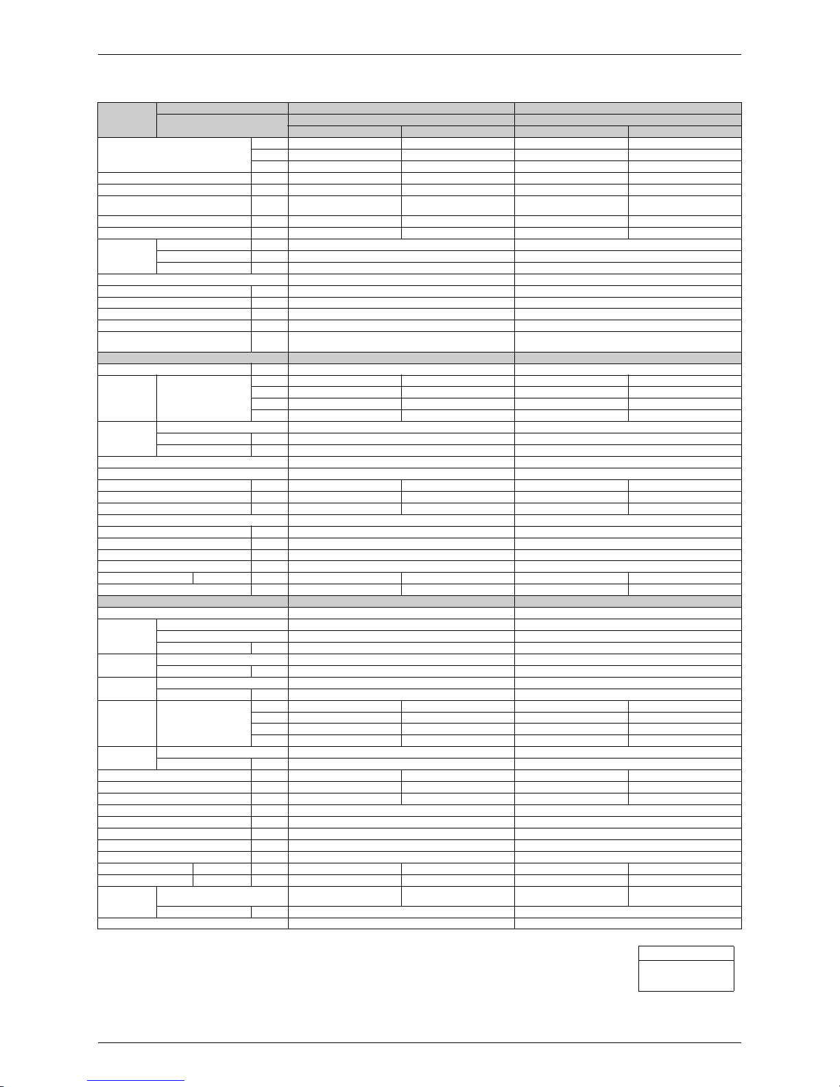
Specifications 9
1.2 Heat Pump
50 Hz, 230 V
Models
Indoor Units FDXS50CVMB FDXS60CVMB
Outdoor Units
RXS50E2(3)V1B RXS60E2(3)V1B
Cooling Heating Cooling Heating
Capacity
Rated (Min. ~ Max.)
kW 5.0 (2.0 ~ 5.3) 5.8 (2.0 ~ 6.0) 6.0 (2.0 ~ 6.5) 7.0 (2.0 ~ 8.0)
Btu/h 17,100 (6,800 ~ 18,100) 19,800 (6,800 ~ 20,500) 20,500 (6,800 ~ 22,200) 23,900 (6,800 ~ 27,300)
kcal/h 4,300 (1,720 ~ 4,560) 4,990 (1,720 ~ 5,160) 5,160 (1,720 ~ 5,590) 6,020 (1,720 ~ 6,880)
Moisture Removal L/h 2.9 — 3.9 —
Running Current (Rated) A 7.3 8.5 9.4 10.2
Power Consumption
Rated (Min. ~ Max.)
W 1,650 (500 ~ 1,930) 1,920 (500 ~ 2,040) 2,130 (500 ~ 2,490) 2,320 (500 ~ 3,180)
Power Factor % 98.3 98.2 98.5 98.9
COP Rated (Min. ~ Max.) W/W 3.03 (4.00 ~ 2.75) 3.02 (4.00 ~ 2.94) 2.82 (4.00 ~ 2.61) 3.02 (4.00 ~ 2.52)
Piping
Connections
Liquid mm
φ
6.4
φ
6.4
Gas mm
φ
12.7
φ
12.7
Drain mm VP20 (O.D.
φ
26 / I.D. φ 20) VP20 (O.D. φ 26 / I.D. φ 20)
Heat Insulation Both Liquid and Gas Pipes Both Liquid and Gas Pipes
Max. Interunit Piping Length m 30 30
Min. Interunit Piping Length m 1.5 1.5
Max. Interunit Height Difference m 20 20
Chargeless m 10 10
Amount of Additional Charge
of Refrigerant
g/m 20 20
Indoor Units FDXS50CVMB FDXS60CVMB
External Static Pressure Pa 40 40
Airflow Rate
m³/min
(cfm)
H 12.0 (424) 12.0 (424) 16.0 (565) 16.0 (565)
M 11.0 (388) 11.0 (388) 14.8 (523) 14.8 (523)
L 10.0 (353) 10.0 (353) 13.5 (477) 13.5 (477)
SL 8.4 (297) 8.4 (297) 11.2 (395) 11.2 (395)
Fan
Type Sirocco Fan Sirocco Fan
Motor Output W 130 130
Speed Steps 5 Steps, Quiet, Auto 5 Steps, Quiet, Auto
Air Direction Control – –
Air Filter Removable / Washable / Mildew Proof Removable / Washable / Mildew Proof
Running Current (Rated) A 0.64 0.64 0.74 0.74
Power Consumption (Rated) W 140 140 160 160
Power Factor % 95.1 95.1 94.0 94.0
Temperature Control Microcomputer Control Microcomputer Control
Dimensions (H × W × D) mm 200 × 900 × 620 200 × 1,100 × 620
Packaged Dimensions (H × W × D) mm 266 × 1,106 × 751 266 × 1,306 × 751
Weight kg 27 30
Gross Weight kg 34 37
Operation Sound H / M / L / SL dBA 37 / 35 / 33 / 31 37 / 35 / 33 / 31 38 / 36 / 34 / 32 38 / 36 / 34 / 32
Sound Power dBA 55 55 56 56
Outdoor Units RXS50E2(3)V1B RXS60E2(3)V1B
Casing Color Ivory White Ivory White
Compressor
Type Hermeti cally Sealed Swing Type Hermetically Sealed Swing Type
Model 2YC36BXD 2YC36BXD
Motor Output W 1,100 1,100
Refrigerant
Oil
Type FVC50K FVC50K
Charge L 0.65 0.65
Refrigerant
Type R-410A R-410A
Charge kg 1.50 1.50
Airflow Rate
m³/min
(cfm)
HH 50.9 (1,798) – 54.2 (1,914) –
H 48.9 (1,727) 45.0 (1,589) 50.9 (1,798) 46.3 (1,635)
L 41.7 (1,473) 45.0 (1,589) 45.0 (1,589) 46.3 (1,635)
Fan
Type Propeller Propeller
Motor Output W 53 53
Running Current (Rated) A 6.66 7.86 8.66 9.46
Power Consumption (Rated) W 1,510 1,780 1,970 2,160
Power Factor % 98.6 98.5 98.9 99.3
Starting Current A 8.5 10.2
Dimensions (H × W × D) mm 735 × 825 × 300 735 × 825 × 300
Packaged Dimensions (H × W × D) mm 797 × 960 × 390 797 × 960 × 390
Weight kg 48 48
Gross Weight kg 53 53
Operation Sound H / L dBA 47 / 44 48 / 45 49 / 46 49 / 46
Sound Power H dBA 61 62 63 63
Conditions
Temperature
Indoor; 27°CDB/19°CWB
Outdoor; 35°CDB/24°CWB
Indoor ; 20°CDB
Outdoor ; 7°CDB / 6°CWB
Indoor; 27°CDB/19°CWB
Outdoor; 35°CDB/24°CWB
Indoor ; 20°CDB
Outdoor ; 7°CDB / 6°CWB
Piping Length m 7.5 7.5
Drawing No. 3D052132 3D052133
Conversion Formulae
kcal/h = kW × 860
Btu/h = kW × 3412
cfm = m³/min × 35.3
Specifications SiBE07-618_C
10 Specifications
50 Hz, 230 V
Models
Indoor Units FDXS50CVMB FDXS60CVMB
Outdoor Units
RXS50F2V1B RXS60F2V1B
Cooling Heating Cooling Heating
Capacity
Rated (Min. ~ Max.)
kW 5.0 (1.7 ~ 5.3) 5.8 (1.7 ~ 6.0) 6.0 (1.7 ~ 6.5) 7.0 (1.7 ~ 8.0)
Btu/h 17,100 (5,800 ~ 18,100) 19,800 (5,800 ~ 20,500) 20,500 (5,800 ~ 22,200) 23,900 (5,800 ~ 27,300)
kcal/h 4,300 (1,460 ~ 4,560) 4,990 (1,460 ~ 5,160) 5,160 (1,460 ~ 5,590) 6,020 (1,460 ~ 6,880)
Moisture Removal L/h 2.9 — 3.9 —
Running Current (Rated) A 7.3 8.5 9.4 10.2
Power Consumption
Rated (Min. ~ Max.)
W 1,650 (440 ~ 1,930) 1,920 (400 ~ 2,040) 2,130 (440 ~ 2,490) 2,320 (400 ~ 3,180)
Power Factor % 98.3 98.2 98.5 98.9
COP Rated (Min. ~ Max.) W/W 3.03 (3.86 ~ 2.75) 3.02 (4.25 ~ 2.94) 2.82 (3.86 ~ 2.61) 3.02 (4.25 ~ 2.52)
Piping
Connections
Liquid mm
φ
6.4
φ
6.4
Gas mm
φ
12.7
φ
12.7
Drain mm VP20 (O.D.
φ
26 / I.D. φ 20) VP20 (O.D. φ 26 / I.D. φ 20)
Heat Insulation Both Liquid and Gas Pipes Both Liquid and Gas Pipes
Max. Interunit Piping Length m 30 30
Min. Interunit Piping Length m 1.5 1.5
Max. Interunit Height Difference m 20 20
Chargeless m 10 10
Amount of Additional Charge
of Refrigerant
g/m 20 20
Indoor Units FDXS50CVMB FDXS60CVMB
External Static Pressure Pa 40 40
Airflow Rate
m³/min
(cfm)
H 12.0 (424) 12.0 (424) 16.0 (565) 16.0 (565)
M 11.0 (388) 11.0 (388) 14.8 (523) 14.8 (523)
L 10.0 (353) 10.0 (353) 13.5 (477) 13.5 (477)
SL 8.4 (297) 8.4 (297) 11.2 (395) 11.2 (395)
Fan
Type Sirocco Fan Sirocco Fan
Motor Output W 130 130
Speed Steps 5 Steps, Quiet, Auto 5 Steps, Quiet, Auto
Air Direction Control – –
Air Filter Removable / Washable / Mildew Proof Removable / Washable / Mildew Proof
Running Current (Rated) A 0.64 0.64 0.74 0.74
Power Consumption (Rated) W 140 140 160 160
Power Factor % 95.1 95.1 94.0 94.0
Temperature Control Microcomputer Control Microcomputer Control
Dimensions (H × W × D) mm 200 × 900 × 620 200 × 1,100 × 620
Packaged Dimensions (H × W × D) mm 266 × 1,106 × 751 266 × 1,306 × 751
Weight kg 27 30
Gross Weight kg 34 37
Operation Sound H / M / L / SL dBA 37 / 35 / 33 / 31 37 / 35 / 33 / 31 38 / 36 / 34 / 32 38 / 36 / 34 / 32
Sound Power dBA 55 55 56 56
Outdoor Units RXS50F2V1B RXS60F2V1B
Casing Color Ivory White Ivory White
Compressor
Type Hermeti cally Sealed Swing Type Hermetically Sealed Swing Type
Model 2YC36BXD 2YC36BXD
Motor Output W 1,100 1,100
Refrigerant
Oil
Type FVC50K FVC50K
Charge L 0.65 0.65
Refrigerant
Type R-410A R-410A
Charge kg 1.50 1.50
Airflow Rate
m³/min
(cfm)
HH 50.9 (1,798) – 54.2 (1,914) –
H 48.9 (1,727) 45.0 (1,589) 50.9 (1,798) 46.3 (1,635)
L 41.7 (1,473) 45.0 (1,589) 45.0 (1,589) 46.3 (1,635)
Fan
Type Propeller Propeller
Motor Output W 53 53
Running Current (Rated) A 6.66 7.86 8.66 9.46
Power Consumption (Rated) W 1,510 1,780 1,970 2,160
Power Factor % 98.6 98.5 98.9 99.3
Starting Current A 8.5 10.2
Dimensions (H × W × D) mm 735 × 825 × 300 735 × 825 × 300
Packaged Dimensions (H × W × D) mm 797 × 960 × 390 797 × 960 × 390
Weight kg 48 48
Gross Weight kg 53 53
Operation Sound H / L dBA 47 / 44 48 / 45 49 / 46 49 / 46
Sound Power H dBA 61 62 63 63
Conditions
Temperature
Indoor; 27°CDB/19°CWB
Outdoor; 35°CDB/24°CWB
Indoor ; 20°CDB
Outdoor ; 7°CDB / 6°CWB
Indoor; 27°CDB/19°CWB
Outdoor; 35°CDB/24°CWB
Indoor ; 20°CDB
Outdoor ; 7°CDB / 6°CWB
Piping Length m 7.5 7.5
Drawing No. 3D057852 3D057854
Conversion Formulae
kcal/h = kW × 860
Btu/h = kW × 3412
cfm = m³/min × 35.3
SiBE07-618_C Specifications
Specifications 11
50 Hz, 230 V
Models
Indoor Units FDXS50CVMB FDXS60CVMB
Outdoor Units
RXS50G2V1B RXS60F3V1B
Cooling Heating Cooling Heating
Capacity
Rated (Min. ~ Max.)
kW 5.0 (1.7 ~ 5.3) 5.8 (1.7 ~ 6.0) 6.0 (1.7 ~ 6.5) 7.0 (1.7 ~ 8.0)
Btu/h 17,100 (5,800 ~ 18,100) 19,800 (5,800 ~ 20,500) 20,500 (5,800 ~ 22,200) 23,900 (5,800 ~ 27,300)
kcal/h 4,300 (1,460 ~ 4,560) 4,990 (1,460 ~ 5,160) 5,160 (1,460 ~ 5,590) 6,020 (1,460 ~ 6,880)
Moisture Removal L/h 2.9 — 3.9 —
Running Current (Rated) A 7.3 8.5 9.4 10.2
Power Consumption
Rated (Min. ~ Max.)
W 1,650 (440 ~ 1,930) 1,920 (400 ~ 2,040) 2,130 (440 ~ 2,490) 2,320 (400 ~ 3,180)
Power Factor % 98.3 98.2 98.5 98.9
COP Rated (Min. ~ Max.) W/W 3.03 (3.86 ~ 2.75) 3.02 (4.25 ~ 2.94) 2.82 (3.86 ~ 2.61) 3.02 (4.25 ~ 2.52)
Piping
Connections
Liquid mm
φ
6.4
φ
6.4
Gas mm
φ
12.7
φ
12.7
Drain mm VP20 (O.D.
φ
26 / I.D. φ 20) VP20 (O.D. φ 26 / I.D. φ 20)
Heat Insulation Both Liquid and Gas Pipes Both Liquid and Gas Pipes
Max. Interunit Piping Length m 30 30
Min. Interunit Piping Length m 1.5 1.5
Max. Interunit Height Difference m 20 20
Chargeless m 10 10
Amount of Additional Charge
of Refrigerant
g/m 20 20
Indoor Units FDXS50CVMB FDXS60CVMB
External Static Pressure Pa 40 40
Airflow Rate
m³/min
(cfm)
H 12.0 (424) 12.0 (424) 16.0 (565) 16.0 (565)
M 11.0 (388) 11.0 (388) 14.8 (523) 14.8 (523)
L 10.0 (353) 10.0 (353) 13.5 (477) 13.5 (477)
SL 8.4 (297) 8.4 (297) 11.2 (395) 11.2 (395)
Fan
Type Sirocco Fan Sirocco Fan
Motor Output W 130 130
Speed Steps 5 Steps, Quiet, Auto 5 Steps, Quiet, Auto
Air Direction Control – –
Air Filter Removable / Washable / Mildew Proof Removable / Washable / Mildew Proof
Running Current (Rated) A 0.64 0.64 0.74 0.74
Power Consumption (Rated) W 140 140 160 160
Power Factor % 95.1 95.1 94.0 94.0
Temperature Control Microcomputer Control Microcomputer Control
Dimensions (H × W × D) mm 200 × 900 × 620 200 × 1,100 × 620
Packaged Dimensions (H × W × D) mm 266 × 1,106 × 751 266 × 1,306 × 751
Weight kg 27 30
Gross Weight kg 34 37
Operation Sound H / M / L / SL dBA 37 / 35 / 33 / 31 37 / 35 / 33 / 31 38 / 36 / 34 / 32 38 / 36 / 34 / 32
Sound Power dBA 55 55 56 56
Outdoor Units RXS50G2V1B RXS60F3V1B
Casing Color Ivory White Ivory White
Compressor
Type Hermeti cally Sealed Swing Type Hermetically Sealed Swing Type
Model 2YC36BXD 2YC36BXD
Motor Output W 1,100 1,100
Refrigerant
Oil
Type FVC50K FVC50K
Charge L 0.65 0.65
Refrigerant
Type R-410A R-410A
Charge kg 1.70 1.50
Airflow Rate
m³/min
(cfm)
HH – – 54.2 (1,914) –
H 50.9 (1,798) 45.0 (1,589) 50.9 (1,798) 46.3 (1,635)
L – – 45.0 (1,589) 46.3 (1,635)
SL 48.9 (1,727) 43.1 (1,522) – –
Fan
Type Propeller Propeller
Motor Output W 53 53
Running Current (Rated) A 6.63 6.82 8.66 9.46
Power Consumption (Rated) W 1,494 1,538 1,970 2,160
Power Factor % 98.0 98.0 98.9 99.3
Starting Current A 7.3 10.2
Dimensions (H × W × D) mm 735 × 825 × 300 735 × 825 × 300
Packaged Dimensions (H × W × D) mm 797 × 960 × 390 797 × 960 × 390
Weight kg 48 48
Gross Weight kg 53 53
Operation Sound H / L dBA 48 / 44 48 / 45 49 / 46 49 / 46
Sound Power H dBA 62 62 63 63
Conditions
Temperature
Indoor; 27°CDB/19°CWB
Outdoor; 35°CDB/24°CWB
Indoor ; 20°CDB
Outdoor ; 7°CDB / 6°CWB
Indoor; 27°CDB/19°CWB
Outdoor; 35°CDB/24°CWB
Indoor ; 20°CDB
Outdoor ; 7°CDB / 6°CWB
Piping Length m 5.0 7.5
Drawing No. 3D060033 3D065477
Conversion Formulae
kcal/h = kW × 860
Btu/h = kW × 3412
cfm = m³/min × 35.3

SiBE07-618_C
12 Printed Circuit Board Connector Wiring Diagram
Part 3
Printed Circuit Board
Connector Wiring Diagram
1. Printed Circuit Board Connector Wiring Diagram..................................13
1.1 Indoor Unit..............................................................................................13
1.2 Outdoor Unit ...........................................................................................15

SiBE07-618_C Printed Circuit Board Connector Wiring Diagram
Printed Circuit Board Connector Wiring Diagram 13
1. Printed Circuit Board Connector Wiring Diagram
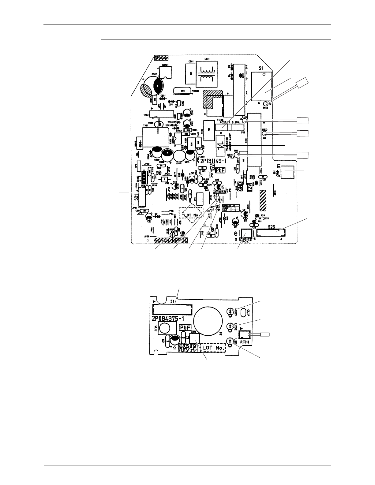
1.1 Indoor Unit
Connectors and
Other Parts
PCB(1): Control PCB
PCB(2): Display PCB
1) S1 Connector for AC fan motor
2) S7 Connector for AC fan motor (Hall IC)
3) S21 Connector for centralized control (HA)
4) S26 Connector for display PCB
5) S32 Connector for indoor heat exchanger thermistor
6) H1, H2, H3 Connector for terminal board
7) GND Connector for terminal board (earth)
8) JA Address setting jumper
∗
Refer to page 127 for detail.
JB Fan speed setting when compressor stops for thermostat OFF
JC Power failure recovery function (auto-restart)
∗
Refer to page 128 for more detail.
9) LED A LED for service monitor (green)
10) FU1(F1U) Fuse (3.15A, 250V)
11) V1(V1TR) Varistor
1) S1 Connector for control PCB
2) SW1 (S1W) Forced operation ON/OFF button
3) LED1 (H1P) LED for HOME LEAVE operation (red)
4) LED2 (H2P) LED for timer (yellow)
5) LED3 (H3P) LED for operation (green)
6) RTH1 (R1T) Room temperature thermistor
Printed Circuit Board Connector Wiring Diagram SiBE07-618_C
14 Printed Circuit Board Connector Wiring Diagram
PCB Detail PCB (1): Control PCB
PCB (2): Display PCB
S1
H2
S7
S26
S32JCJBJA
S21
2P131149-1
LED A
FU1
H1
H3
V1
GND
S1
LED3
LED2
LED1
SW1
RTH1
2P084375-1

SiBE07-618_C Printed Circuit Board Connector Wiring Diagram
Printed Circuit Board Connector Wiring Diagram 15
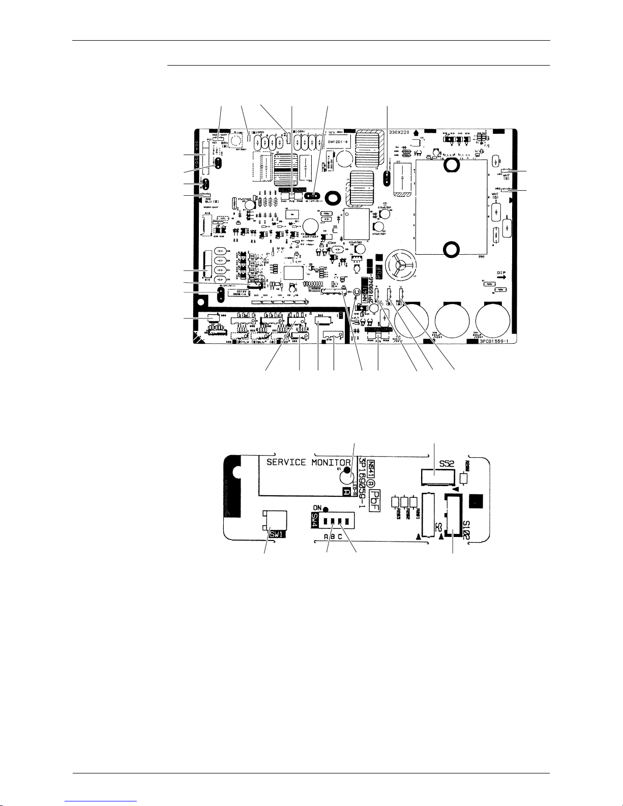
1.2 Outdoor Unit
Connectors and
Other Parts
PCB (1): Main PCB
PCB (2): Service Monitor PCB
1) S10 Connector for terminal board (indoor - outdoor transmission)
2) S20 Connector for electronic expansion valve coil
3) S40 Connector for overload protector
4) S51, S101 Connector for service monitor PCB
5) S70 Connector for fan motor
6) S80 Connector for four way valve coil
7) S90 Connector for thermistors
(outdoor temperature, outdoor heat exchanger, discharge pipe)
8) AC1, AC2 Connector for terminal board (power supply)
9) HR1, HR2 Connector for reactor
10) E1, E2 Connector for earth
11) U, V, W Connector for compressor
12) FU1 Fuse (30 A, 250 V)
13) FU2, FU3 Fuse (3.15 A, 250 V)
14) V2, V3, V5, V6, V11 Varistor
1) S52, S102 Connector for main PCB
2) LED A LED for service monitor (green)
3) SW1 Forced operation ON/OFF button
4) SW4-B Switch for facility setting
∗
Refer to page 128 for detail.
5) SW4-C Switch for improvement of defrost performance
∗
Refer to page 128 for detail.
Printed Circuit Board Connector Wiring Diagram SiBE07-618_C
16 Printed Circuit Board Connector Wiring Diagram
PCB Detail PCB (1): Main PCB
PCB (2): Service Monitor PCB
V3
V11
AC1 E1 E2
FU2
(3.15A)
HR1
HR2
FU3
(3.15A)
2P169046-1
2P169046-5
2P169046-7
S40
S20
S70
S90
S51 W V U
S10
AC2
S101
V5
S80
V6
V2
FU1
(30A)
S102
SW1
3P169059-1
LED A
SW4-CSW4-B
S52

SiBE07-618_C
Function and Control 17
Part 4
Function and Control
1. Main Functions......................................................................................18
1.1 Temperature Control ..............................................................................18
1.2 Frequency Principle................................................................................18
1.3 Fan Speed Control for Indoor Units........................................................20
1.4 Program Dry Operation ..........................................................................21
1.5 Automatic Operation...............................................................................22
1.6 Thermostat Control.................................................................................23
1.7 NIGHT SET Mode ..................................................................................24
1.8 HOME LEAVE Operation .......................................................................25
1.9 Inverter POWERFUL Operation .............................................................26
1.10 Other Functions......................................................................................27
2. Function of Thermistor ..........................................................................28
3. Control Specification .............................................................................29
3.1 Mode Hierarchy ......................................................................................29
3.2 Frequency Control..................................................................................30
3.3 Controls at Mode Changing / Start-up....................................................32
3.4 Discharge Pipe Temperature Control.....................................................33
3.5 Input Current Control ..............................................................................34
3.6 Freeze-up Protection Control .................................................................35
3.7 Heating Peak-cut Control .......................................................................35
3.8 Outdoor Fan Control...............................................................................36
3.9 Liquid Compression Protection Function................................................36
3.10 Defrost Control .......................................................................................37
3.11 Electronic Expansion Valve Control .......................................................38
3.12 Malfunctions ...........................................................................................41
3.13 Forced Operation Mode .........................................................................42
Main Functions SiBE07-618_C
18 Function and Control
1. Main Functions
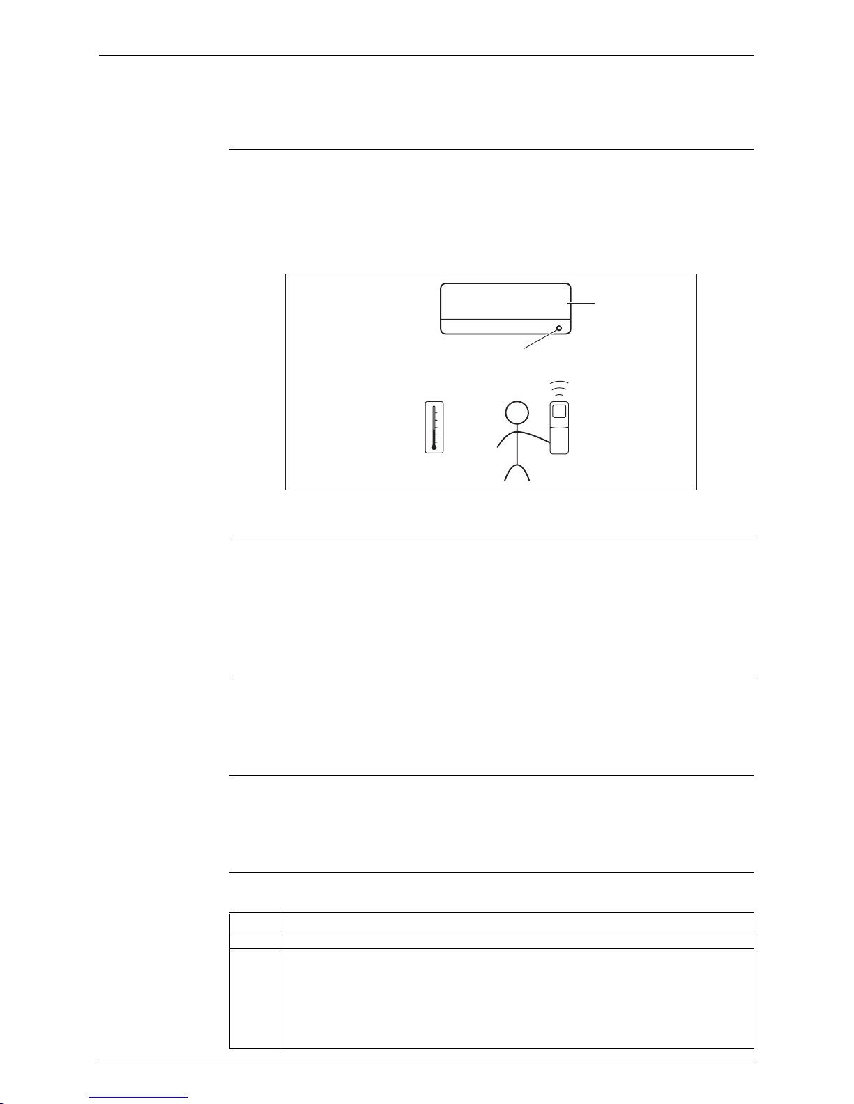
1.1 Temperature Control
Definitions of
Temperatures
The definitions of temperatures are classified as following.
Room temperature: temperature of lower part of the room
Set temperature: temperature set by remote controller
Room thermistor temperature: temperature detected by room temperature thermistor
Target temperature: temperature determined by microcomputer
★
The illustration is for wall mounted type as representative.
Temperature
Control
The temperature of the room is detected by the room temperature thermistor. However, there is
difference between the “temperature detected by room temperature thermistor” and the
“temperature of lower part of the room”, depending on the type of the indoor unit or installation
condition. Practically, the temperature control is done by the “target temperature appropriately
adjusted for the indoor unit” and the “temperature detected by room temperature thermistor”.
1.2 Frequency Principle
Main Control
Parameters
The compressor is frequency-controlled during normal operation. The target frequency is set by
the following 2 parameters coming from the operating indoor unit:
The load condition of the operating indoor unit
The difference between the room thermistor temperature and the target temperature
Additional
Control
Parameters
The target frequency is adapted by additional parameters in the following cases:
Frequency restrictions
Initial settings
Forced cooling operation
Inverter Principle To regulate the capacity, a frequency control is needed. The inverter makes it possible to vary
the rotation speed of the compressor. The following table explains the conversion principle:
Target temperature
Set temperature
Room temperature
Room thermistor temperature
(R12321)
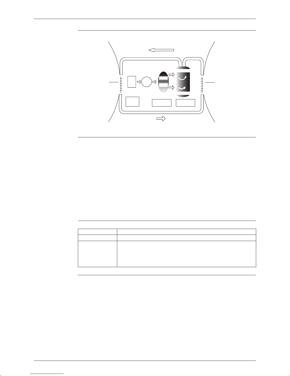
Phase Description
1 The supplied AC power source is converted into the DC power source for the present.
2 The DC power source is reconverted into the three phase AC power source with variable
frequency.
When the frequency increases, the rotation speed of the compressor increases resulting
in an increased refrigerant circulation. This leads to a higher amount of the heat
exchange per unit.
When the frequency decreases, the rotation speed of the compressor decreases
resulting in a decreased refrigerant circulation. This leads to a lower amount of the heat
exchange per unit.
SiBE07-618_C Main Functions
Function and Control 19
Drawing of
Inverter
The following drawing shows a schematic view of the inverter principle:
Inverter Features The inverter provides the following features:
The regulating capacity can be changed according to the changes in the outdoor
temperature and cooling / heating load.
Quick heating and quick cooling
The compressor rotational speed is increased when starting the heating (or cooling). This
enables to reach the set temperature quickly.
Even during extreme cold weather, the high capacity is achieved. It is maintained even when
the outdoor temperature is 2°C.
Comfortable air conditioning
A fine adjustment is integrated to keep the room temperature constant.
Energy saving heating and cooling
Once the set temperature is reached, the energy saving operation enables to maintain the
room temperature at low power.
Frequency Limits The following functions regulate the minimum and maximum frequency:
Forced Cooling
Operation
Refer to “Forced operation mode” on page
42 for detail
.
50 Hz
60 Hz
Refrigerant circulation rate (high)
high f
low f
freq=variable
Refrigerant circulation rate (low)
high speed
low speed
(R2812)
Amount of heat
exchanged air (large)
Amount of heat
exchanged air (small)
freq=
constant
capacity=
variable
AC
power
DC
power
Amount of heat
exchanged air (large)
Amount of heat
exchanged air (small)
Frequency Functions
Low Four way valve operation compensation. Refer to page 32.
High Compressor protection function. Refer to page 33.
Discharge pipe temperature control. Refer to page 33.
Input current control. Refer to page 34.
Freeze-up protection control. Refer to page 35.
Heating peak-cut control. Refer to page 35.
Defrost control. Refer to page 37.
Main Functions SiBE07-618_C
20 Function and Control
1.3 Fan Speed Control for Indoor Units
Outline Phase control and fan speed control contains 9 steps: LLL, LL, SL, L, ML, M, MH, H, and HH.
The airflow rate can be automatically controlled depending on the difference between the room
thermistor temperature and the target temperature. This is done through phase control and Hall
IC control.
For more information about Hall IC, refer to the troubleshooting for fan motor on page 64.
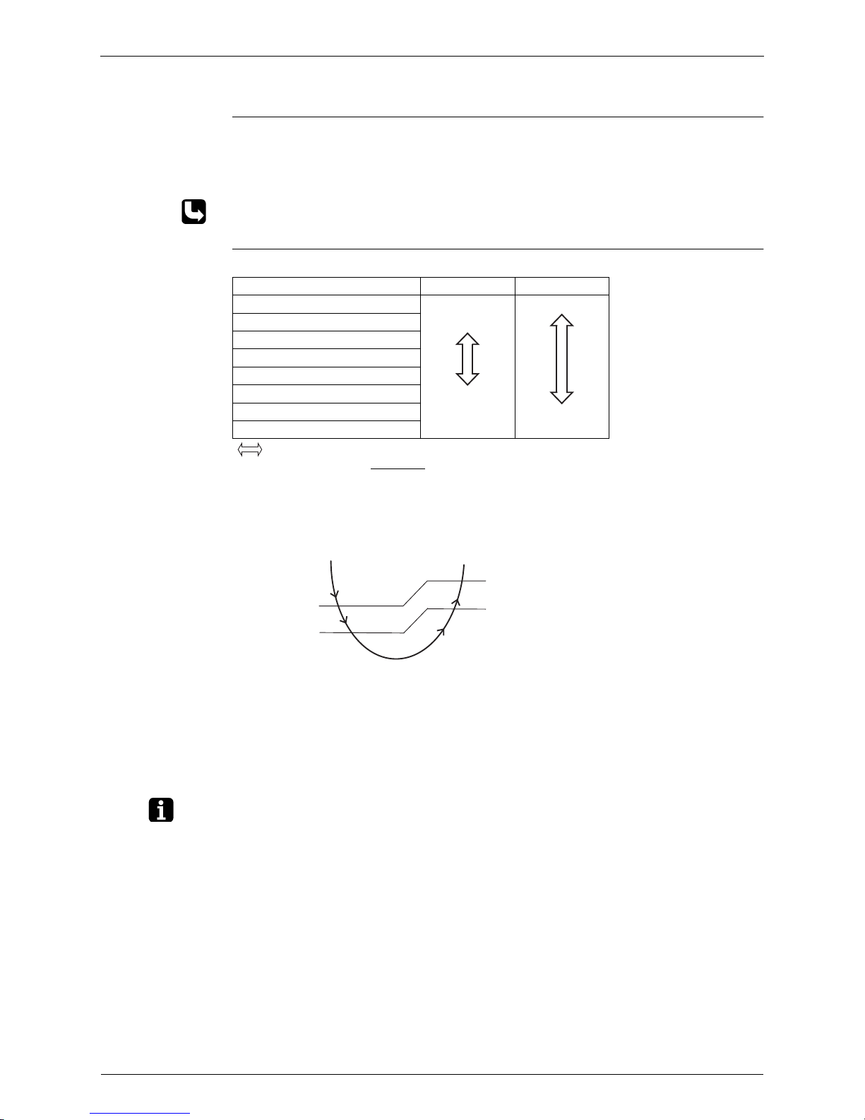
Automatic Fan
Speed Control
In automatic fan speed operation, the step “SL” is not available.
= The airflow rate is automatically controlled within this range when the FAN setting
button is set to automatic
.
<Cooling>
The following drawing explains the principle of fan speed control for cooling.
<Heating>
On heating mode, the fan speed is regulated according to the indoor heat exchanger
temperature and the difference between the room thermistor temperature and the target
temperature.
Note: 1. During POWERFUL operation, the fan rotates at H tap + 50 rpm.
2. The fan stops during defrost operation.
Step Cooling Heating
LLL
LL
L
ML
M
MH
H
HH (POWERFUL)
(R11505)
(R6834)
+1.5˚C
+0.5˚C
+2˚C
+1˚C
M
ML
L
fan speed
(R12390)
Difference between the room thermistor
temperature and the target temperature
 Loading...