

Daikin RKS42G2V1B, RXG50KV2C, RXL25G2V1B, RKS42J2V1B, RXG50JV2C Service Manual
...
REMOVAL
PROCEDURE
Si001070
SERVICE MANUAL
2.5/4.2/4.6/5.0 kW Class
Outdoor Unit
Inverter
Pair Type

Service Manual
Removal Procedure
Outdoor Unit
zCooling Only zHeat Pump
RKS42G2V1B RXG50JV2C
RXG50KV2C
RKS42J2V1B
RXL25G2V1B
RXL25G3V1B
RXS42G2V1B
RXS42J2V1B
RXS46JV2C
ARXS42G2V1B
Si001070
Table of Contents
1. Removal of Outer Panels........................................................................2
2. Removal of Electrical Box .......................................................................4
3. Removal of PCB......................................................................................9
4. Removal of Partition Plate / Sound Blankets ........................................14
5. Removal of Outdoor Fan / Fan Motor ...................................................16
6. Removal of Thermistors........................................................................20
7. Removal of Drain Pan Heater ASSY (Pattern 1)...................................21
8. Removal of Drain Pan Heater ASSY (Pattern 2)...................................23
9. Removal of Four Way Valve / Electronic Expansion Valve...................26
10.Removal of Compressor .......................................................................29
Note:
The illustrations may be slightly different depending on the model.
The illustrations are for heat pump models as representative.
Removal Procedure 1
Removal of Outer Panels Si001070
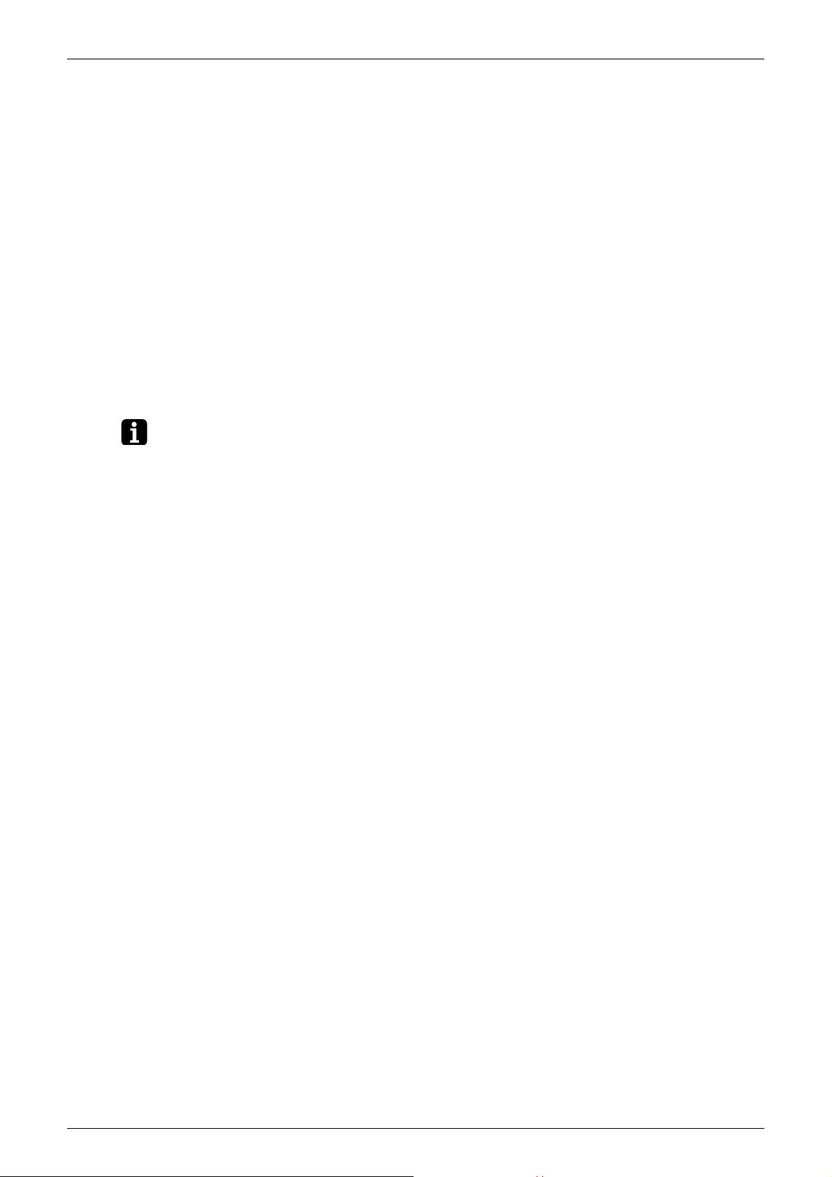
1. Removal of Outer Panels
Procedure Warning Be sure to wait 10 minutes or more after turning off all power supplies
before disassembling work.
Step
1. Features
Procedure Points
Illustrations are slightly
+
different depending on the
model.
DAIKIN
INVERTER
(R7186)
Some models do not have
guard nets.
2. Remove the panels.
1
Remove the screw and
remove the drain pan
heater cover.
Drain pan
heater cover
Guard net
(R18392)
(R9329)
Some models do not have a
drain pan heater cover.
2 Removal Procedure
Si001070 Removal of Outer Panels
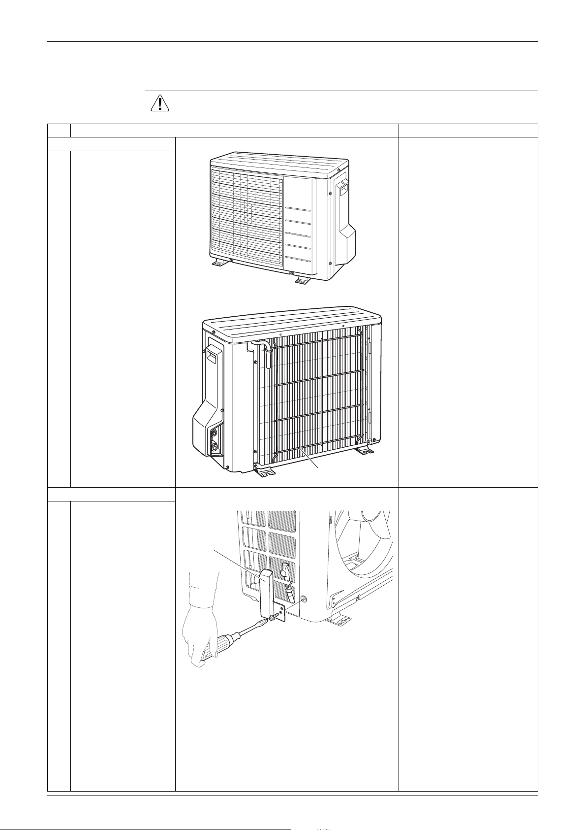
Step
2
Remove the 2 screws
to remove the top
panel, and 7 screws to
remove the front panel.
3
Remove the 4 screws
and remove the
discharge grille.
Hooks
Procedure Points
Top panel
Discharge grille
Front panel
Hooks
(R12305)
The front panel has 4 hooks.
When reassembling, make
sure to fit the 4 hooks.
4
Remove the screw and
remove the stop valve
cover.
(R9364)
Stop
valve
cover
(R8139)
Shield plate
The stop valve cover is
united with the shield plate.
When reassembling, make
sure to fit the 5 hooks.
(R12213)
Removal Procedure 3
Removal of Electrical Box Si001070
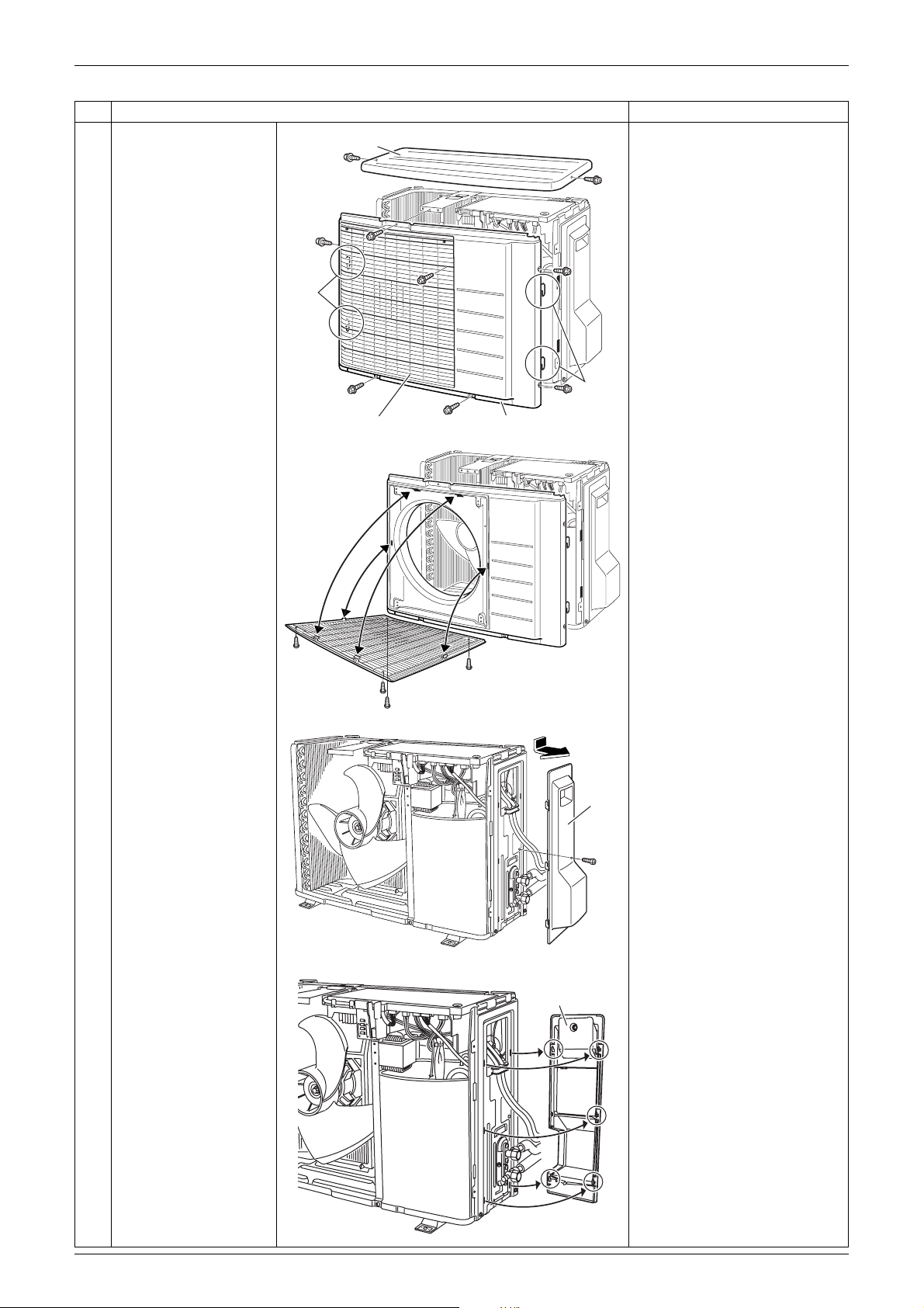
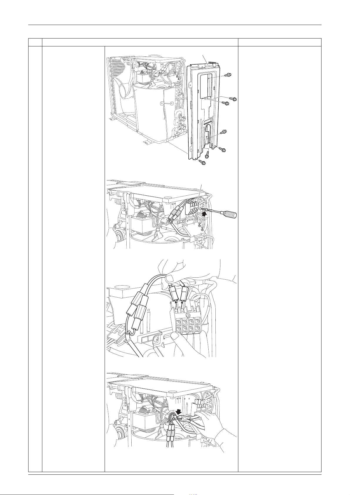
2. Removal of Electrical Box
Procedure Warning Be sure to wait 10 minutes or more after turning off all power supplies
before disassembling work.
Step
1. Disconnect the
connecting wires.
1
Remove the 3 screws
to remove the wiring
fixture.
Then remove the all
screws to disconnect
the power supply
cables and the
connecting wires.
Connecting
wire
Procedure Points
When reassembling, fasten
the wires with screws on the
Terminal
board
Power
supply
cable
terminal board.
2. Remove the electrical
box.
1
Release the outdoor
temperature thermistor.
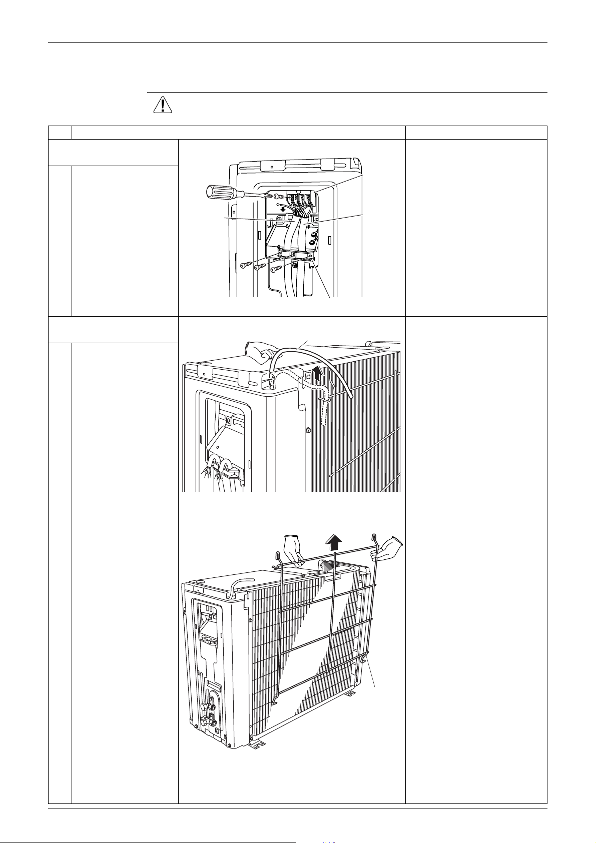
2
Lift up the guard net
and remove it.
Wiring fixture
Outdoor temperature thermistor
(R12192)
(R12193)
Guard net
(R8143)
4 Removal Procedure
Si001070 Removal of Electrical Box
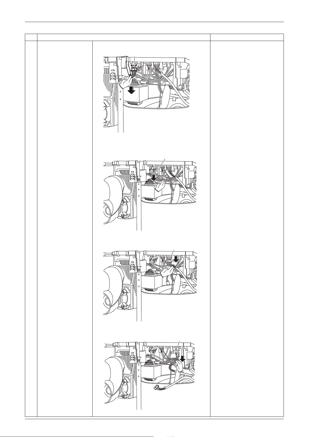
Step
3
Remove the 7 screws,
and remove the right
side panel.
4
Remove the screw of
the terminal board.
Procedure Points
Right side panel
(R9365)
Terminal strip
5
Disconnect the
connectors of the drain
pan heater.
6
Cut the clamp.
(R9366)
(R9367)
Some models do not have a
drain pan heater.
(R9368)
Removal Procedure 5
Removal of Electrical Box Si001070
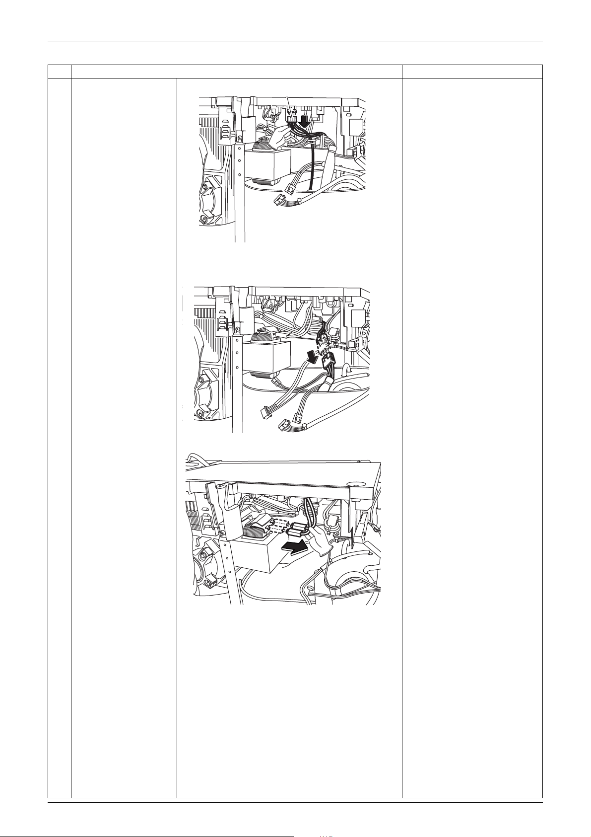
Step
7
Disconnect the
connector for the fan
motor [S70].
8
Disconnect the
connector for the
overload protector
[S40].
Procedure Points
For removal procedure of the
[S70]
fan motor lead wire, refer to
“Removal of Outdoor Fan /
Fan Motor”.
(R0254)
[S40]
9
Disconnect the
connector for the
electronic expansion
valve coil [S20].
10
Disconnect the
connector for the four
way valve coil [S80].
(R0255)
[S20]
(R0256)
[S80]
(R0257)
6 Removal Procedure
Si001070 Removal of Electrical Box
Step
11
Disconnect the
connector for the
thermistors [S90].
12
Disconnect the relay
connector for the
compressor.
Procedure Points
[S90]
(R0258)
13
Disconnect the 2
connectors for the
reactor.
(R0259)
(R0260)
Removal Procedure 7

Removal of Electrical Box Si001070
Step
14
Release the discharge
pipe thermistor.
15
Detach the clamp for
the thermistors from the
electrical box.
Procedure Points
Be careful not to lose the clip
for the thermistor.
Clip
Discharge
pipe thermistor
(R12197)
(R12279)
16
Remove the screw in
front of the electrical
box.
17
Lift and remove the
electrical box.
(R12196)
(R0262)
(R0263)
(R0264)
8 Removal Procedure
Si001070 Removal of PCB
3. Removal of PCB
Procedure Warning Be sure to wait 10 minutes or more after turning off all power supplies
before disassembling work.
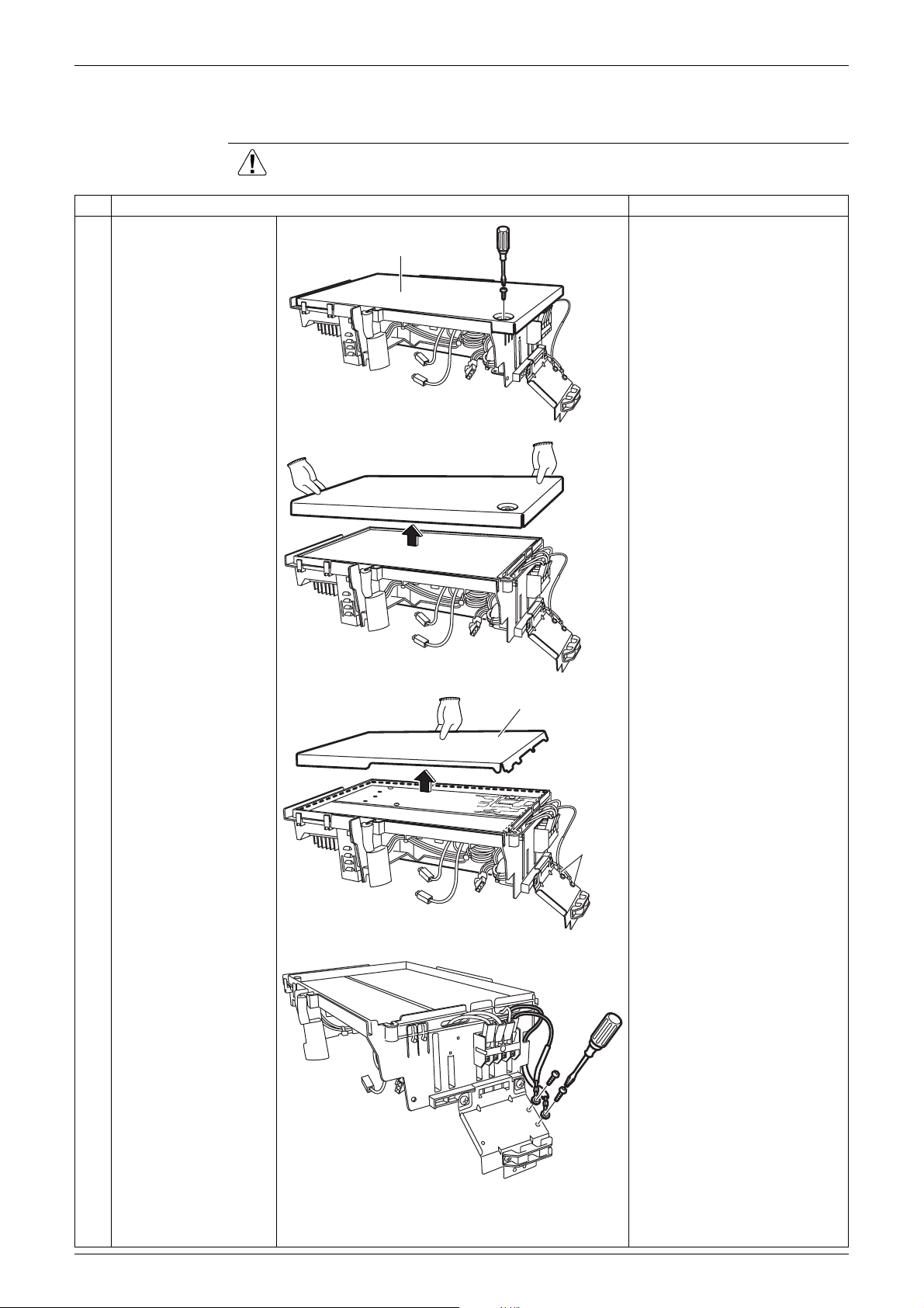
Step
1
Remove the screw and
remove the electrical
box cover.
Procedure Points
Preparation
Electrical box cover
Remove the panels
according to the “Removal of
Outer Panels”.
Remove the electrical box
according to the “Removal of
Electrical Box”.
(R12274)
2
Detach the insulation
sheet.
3
Remove the 2 screws
of the earth terminals.
Insulation
sheet
(R8156)
Earth
terminals
(R8157)
The trimmed part goes front.
(R8158)
Removal Procedure 9
 Loading...