

Daikin FTXS30HVJU, FTXS36HVJU, RKS30HVJU, RKS36HVJU, RXS30HVJU Engineering Data
...
EDUS04-924A
H-Series
- Cooling Only / Heat Pump -

EDUS04-924A
Room Air Conditioners H-Series 1
Split-System
Room Air Conditioners
H-Series
1. Power Supply ..............................................................................................3
2. Functions.....................................................................................................4
3. Specifications ..............................................................................................5
3.1 Cooling Only - 60 Hz, 208 - 230 V................................................................ 5
3.2 Heat Pump - 60 Hz, 208 - 230 V ................................................................. 6
4. Dimensions .................................................................................................7
5. Wiring Diagrams..........................................................................................8
6. Piping Diagrams..........................................................................................9
6.1 Indoor Unit.................................................................................................... 9
6.2 Outdoor Unit ............................................................................................... 10
7. Capacity Tables ........................................................................................11
7.1 Cooling Only............................................................................................... 11
7.2 Heat Pump ................................................................................................. 13
7.3 Capacity correction factor by the length of refrigerant piping (Reference). 18
8. Operation Limit..........................................................................................19
9. Sound Level ..............................................................................................20
9.1 Measuring Location .................................................................................... 20
9.2 Octave Band Level ..................................................................................... 21
10.Electric Characteristics..............................................................................23
11.Installation Manual ....................................................................................24
11.1 Indoor Unit.................................................................................................. 24
11.2 Outdoor Unit ............................................................................................... 34
12.Operation Manual Safety Considerations .................................................46
13.Optional Accessories ................................................................................82
13.1 Option List .................................................................................................. 82
13.2 <BRC944B2> Wired Remote Controller..................................................... 83
13.3 <KRP413AB1S> Wiring Adaptor for Timer Clock / Remote Controller ...... 97
13.4 <KRP928BB2S> Interface Adaptor for DIII-NET
(Residential Air Conditioner) 101
Single Split Duct-Free System
Cooling Only
FTXS30HVJU
FTXS36HVJU
RKS30HVJU
RKS36HVJU
Heat Pump
FTXS30HVJU
FTXS36HVJU
RXS30HVJU
RXS36HVJU

EDUS04-924A
2 Room Air Conditioners H-Series
13.5 <KPW5E112> Air Direction Adjustment Grille.......................................... 104
13.6 <KKPR945A4> Drain Plug ....................................................................... 105

EDUS04-924A Power Supply
Room Air Conditioners H-Series 3
1. Power Supply
Note: Power Supply Intake ; Outdoor Unit
Indoor Unit Outdoor Unit Power Supply
Single Split
Duct-Free System
FTXS30HVJU RKS30HVJU
1
, 208 - 230 V, 60 Hz
FTXS36HVJU RKS36HVJU
FTXS30HVJU RXS30HVJU
FTXS36HVJU RXS36HVJU
Functions EDUS04-924A
4 Room Air Conditioners H-Series
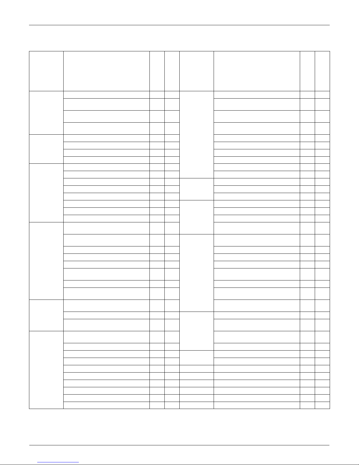
2. Functions
Category Functions
FTXS30/36HVJU
RKS30/36HVJU
FTXS30/36HVJU
RXS30/36HVJU
Category Functions
FTXS30/36HVJU
RKS30/36HVJU
FTXS30/36HVJU
RXS30/36HVJU
Basic Function Inverter (with Inverter Power Control) Health &
Clean
Air-Purifying Filter — —
Operation Limit for Cooling (°FDB)
14~
114.8
14~
114.8
Photocatalytic Deodorizing Filter — —
Operation Limit for Heating (°FWB) —
5~
75
Air-Purifying Filter with Photocatalytic
Deodorizing Function
——
PAM Control
Titanium Apatite Photocatalytic
Air-Purifying Filter
Compressor Oval Scroll Compressor — — Air Filter (Prefilter)
Swing Compressor Wipe-Clean Flat Panel
Rotary Compressor — — Washable Grille — —
Reluctance DC Motor MOLD PROOF Operation — —
Comfortable
Airflow
Power-Airflow Louver (Horizontal Blade) — — Heating Dry Operation — —
Power-Airflow Dual Louvers Good-Sleep Cooling Operation — —
Power-Airflow Diffuser — — Timer WEEKLY TIMER
Wide-Angle Fins (Vertical Blades) 24-Hour ON/OFF TIMER
Vertical Auto-Swing (Up and Down) NIGHT SET Mode
Horizontal Auto-Swing (Right and Left) Worry Free
“Reliability &
Durability”
Auto-Restart (after Power Failure)
3-D Airflow Self-Diagnosis (Digital, LED) Display
COMFORT AIRFLOW Operation Wiring Error Check Function — —
Comfort
Control
Auto Fan Speed
Anticorrosion Treatment of Outdoor
Heat Exchanger
Indoor Unit Quiet Operation
Flexibility Multi-Split / Split Type Compatible
Indoor Unit
——
NIGHT QUIET Mode (Automatic) — — H/P, C/O Compatible Indoor Unit
Outdoor Unit Quiet Operation (Manual) Flexible Power Supply Correspondence — —
INTELLIGENT EYE Operation Chargeless 32 ft 32 ft
Quick Warming Function
(Preheating Operation)
— Either Side Drain (Right or Left)
Hot-Start Function — Power Selection — —
Automatic Defrosting —
Low Temperature Cooling Operation
(–15°C) (5°F)
Operation
Automatic Operation —
°F/°C Changeover R/C Temperature
Display (factory setting : °F)
Program Dry Function Remote
Control
5-Rooms Centralized Controller (Option)
Fan Only
Remote Control Adaptor
(Normal Open-Pulse Contact) (Option)
Lifestyle
Convenience
New POWERFUL Operation
(Non-Inverter)
——
Remote Control Adaptor
(Normal Open Contact) (Option)
Inverter POWERFUL Operation DIII-NET Compatible (Adaptor) (Option)
Priority-Room Setting — — Remote
Controller
Wireless
COOL / HEAT Mode Lock — — Wired (Option)
HOME LEAVE Operation — —
ECONO Operation
Indoor Unit ON/OFF Button
Signal Receiving Sign
R/C with Back Light
Temperature Display — —
Note: : Holding Functions
— : No Functions
EDUS04-924A Specifications
Room Air Conditioners H-Series 5
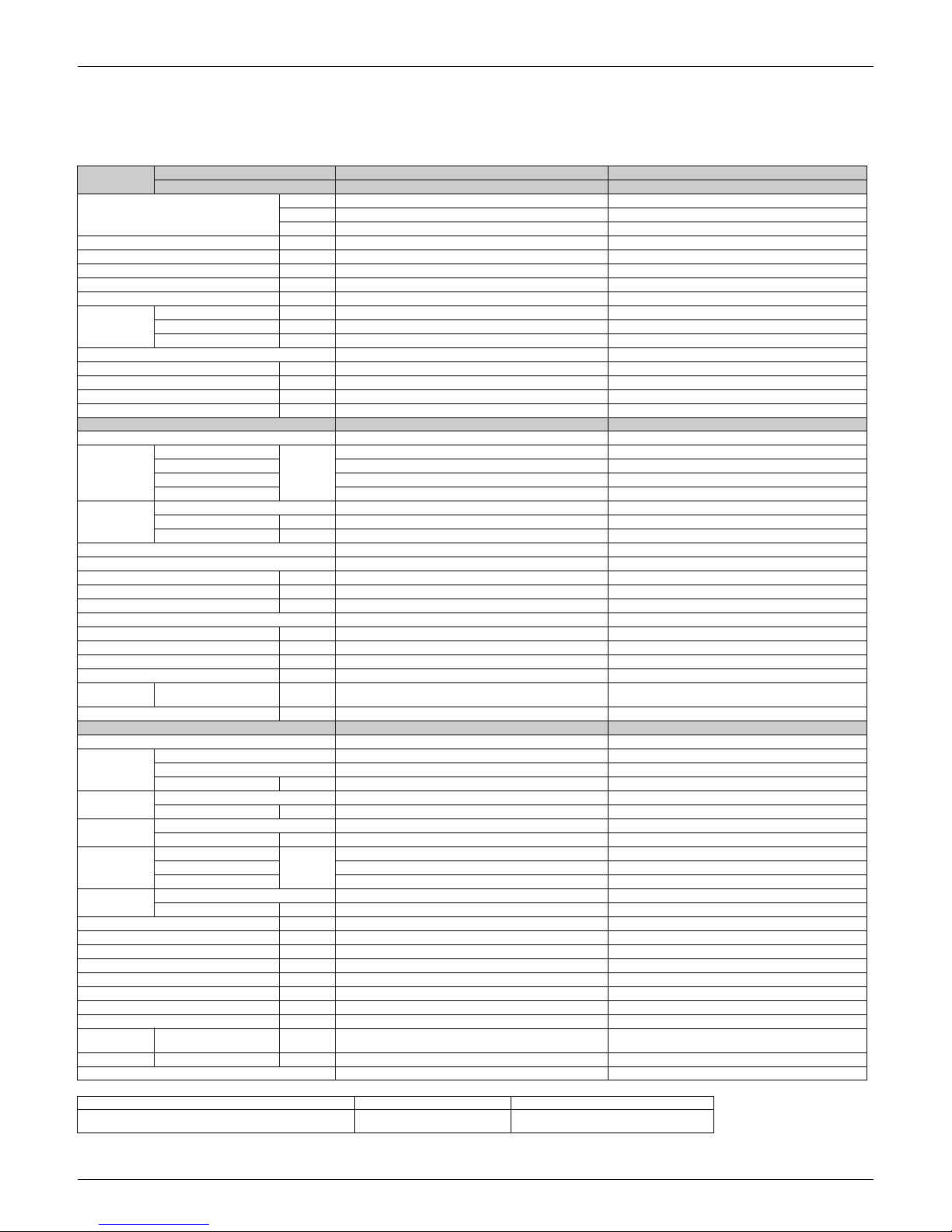
3. Specifications
3.1 Cooling Only - 60 Hz, 208 - 230 V
The data are based on the conditions shown in the table below.
Model
Indoor Unit FTXS30HVJU FTXS36HVJU
Outdoor Unit RKS30HVJU RKS36HVJU
Capacity
Rated (Min. ~ Max.)
kW 8.8 (3.0 ~ 8.8) 10.2-10.5 (3.0 ~ 10.2-10.5)
Btu/h 30,000 (10,200 ~ 30,000) 35,000-36,000 (10,200 ~ 35,000-36,000)
kcal/h 7,570 (2,580 ~ 7,570) 8,770-9,030 (2,580 ~ 8,770-9,030)
Running Current (Rated) A 13.6-12.2 19.4-18.8
Power Consumption Rated
(Min. ~ Max.)
W 2,800 (620 ~ 2,800) 4,000-4,300 (620 ~ 4,000-4,300)
Power Factor (Rated) % 99.0-99.8 99.1-99.4
COP (Rated) W/W 3.14 (4.84 ~ 3.14) 2.55-2.44 (4.84 ~ 2.55-2.44)
EER (Rated)
Btu/h·W
10.71 (16.45 ~ 10.71) 8.75-8.37 (16.45 ~ 8.75-8.37)
Piping
Connections
Liquid in. (mm) 3/8
(9.5) 3/8 (9.5)
Gas in. (mm) 5/8 (15.8) 5/8 (15.8)
Drain in. (mm) 11/16 (17.5) 11/16 (17.5)
Heat Insulation Both Liquid and Gas Pipes Both Liquid and Gas Pipes
Max. Interunit Piping Length ft (m) 98.4 (30) 98.4 (30)
Max. Interunit Height Difference ft (m) 65.6 (20) 65.6 (20)
Chargeless ft (m) 32 (10) 32 (10)
Amount of Additional Charge of Refrigerant oz/ft (g/m) 0.55 (16) 0.55 (16)
Indoor Unit FTXS30HVJU FTXS36HVJU
Front Panel Color White White
Airflow Rate
H
m³/min
(cfm)
20.0 (706) 21.8 (770)
M 17.3 (611) 18.0 (635)
L 14.7 (519) 14.7 (519)
SL 13.4 (473) 13.4 (473)
Fan
Type Cross Flow Fan Cross Flow Fan
Motor Output W 64 64
Speed Steps 5 Steps, Quiet, Auto 5 Steps, Quiet, Auto
Air Direction Control Right, Left, Horizontal, Downward Right, Left, Horizontal, Downward
Air Filter Removable / Washable / Mildew Proof Removable / Washable / Mildew Proof
Running Current (Rated) A 0.38-0.34 0.38-0.34
Power Consumption (Rated) W 77 77
Power Factor (Rated) % 97.4-98.5 97.4-98.5
Temperature Control Microcomputer Control Microcomputer Control
Dimensions (H × W × D) in. (mm) 13-3/8 × 47-1/4 × 9-7/16 (340 x 1200 x 240) 13-3/8 × 47-1/4 × 9-7/16 (340 x 1200 x 240)
Packaged Dimensions (H × W × D) in. (mm) 12-13/16 × 51-9/16 × 16-7/8 (325 x 1310 x 429) 12-13/16 × 51-9/16 × 16-7/8 (325 x 1310 x 429)
Weight Lbs (kg) 38 (17) 38 (17)
Gross Weight Lbs (kg) 51 (23) 51 (23)
Operation
Sound
H / M / L / SL dB(A) 47 / 45 / 40 / 37 49 / 45 / 40 / 37
Sound Power dB(A) 63 65
Outdoor Unit RKS30HVJU RKS36HVJU
Casing Color Ivory White Ivory White
Compressor
Type Hermetically Sealed Swing Type Hermetically Sealed Swing Type
Model 2YC63HXD 2YC63HXD
Motor Output W 2,030 2,030
Refrigerant Oil
Type FVC50K FVC50K
Charge oz (kg) 25.5 (0.8) 25.5 (0.8)
Refrigerant
Type R-410A R-410A
Charge Lbs (kg) 6.17 (2.8) 6.17 (2.8)
Airflow Rate
HH
m³/min
(cfm)
81.2 (2,867) 81.2 (2,867)
H 74.4 (2,627) 74.4 (2,627)
SL 65.6 (2,316) 65.6 (2,316)
Fan
Type Propeller Propeller
Motor Output W 200 200
Running Current (Rated) A 13.22-11.86 19.02-18.46
Power Consumption (Rated) W 2,723 3,923-4,223
Power Factor (Rated) % 99.0-99.8 99.2-99.5
Starting Current A 18.9 19.4
Dimensions (H × W × D) in. (mm) 38-15/16 × 37 × 12-5/8 (989 x 940 x 321) 38-15/16 × 37 × 12-5/8 (989 x 940 x 321)
Packaged Dimensions (H × W × D) in. (mm) 44-1/8 × 38 × 15-1/4 (1121 x 965 x 387) 44-1/8 × 38 × 15-1/4 (1121 x 965 x 387)
Weight Lbs (kg) 178 (81) 178 (81)
Gross Weight Lbs (kg) 198 (90) 198 (90)
Operation
Sound
H / SL dB(A) 54 / 51 54 / 51
Sound Power H dB(A) 68 68
Drawing No. 3D072241 3D072242
Cooling Piping Length Conversion Formulae
Indoor :80°FDB(27°CDB), 67°FWB(19.4°CWB),
Outdoor ; 95°FDB( 35°CDB) / 75°FWB( 24°CWB)
25 ft (7.5 m)
kcal/h = kW × 860 / Btu/h = kW × 3412 cfm
= m³/min × 35.3

Specifications EDUS04-924A
6 Room Air Conditioners H-Series
3.2 Heat Pump - 60 Hz, 208 - 230 V
The data are based on the conditions shown in the table below.
Model
Indoor Unit FTXS30HVJU FTXS36HVJU
Outdoor Unit
RXS30HVJU RXS36HVJU
Cooling Heating Cooling Heating
Capacity
Rated (Min. ~ Max.)
kW 8.8 (3.0 ~ 8.8) 10.2 (3.0 ~ 10.2) 10.2-10.5 (3.0 ~ 10.2-10.5) 10.5-11.1 (3.0 ~ 10.5-11.1)
Btu/h
30,000
(10,200 ~ 30,000)
34,800
(10,200 ~ 34,800)
35,000-36,000
(10,200 ~ 35,000-36,000)
36,000-38,000
(10,200 ~ 36,000-38,000)
kcal/h
7,570
(2,580 ~ 7,570)
8,770
(2,580 ~ 8,770)
8,770-9,030
(2,580 ~ 8,770-9,030)
9,030-9,550
(2,580 ~ 9,030-9,550)
Running Current (Rated) A 13.6-12.2 18.9-17.1 19.4-18.8 18.4-18.4
Power Consumption
Rated
(Min~Max.)
W 2,800 (620 ~ 2,800) 3,900 (620 ~ 3,900) 4,000-4,300 (620~4,000-4,300) 3,800-4,200 (620~3,800-4,200)
Power Factor (Rated) % 99.0-99.8 99.2-99.2 99.1-99.4 99.3-99.2
COP (Rated) W/W 3.14 (4.84 ~ 3.14) 2.62 (4.84 ~ 2.62) 2.55-2.44 (4.84 ~ 2.55-2.44) 2.76-2.64 (4.84 ~ 2.76-2.64)
EER (Rated)
Btu/h·W
10.71 (16.45 ~ 10.71) 8.92 (16.45 ~ 8.92) 8.75-8.37(16.45 ~ 8.75-8.37) 9.47-9.05(16.45 ~ 9.47-9.05)
Piping
Connections
Liquid in. (mm) 3/8 (9.5) 3/8 (9.5)
Gas in. (mm) 5/8 (15.8) 5/8 (15.8)
Drain in. (mm) 11/16 (17.5) 11/16 (17.5)
Heat Insulation Both Liquid and Gas Pipes Both Liquid and Gas Pipes
Max. Interunit Piping Length ft (m) 98.4 (30) 98.4 (30)
Max. Interunit Height Difference ft (m) 65.6 (20) 65.6 (20)
Chargeless ft (m) 32 (10) 32 (10)
Amount of Additional Charge of Refrig.
oz/ft 0.55 0.55
Indoor Unit FTXS30HVJU FTXS36HVJU
Front Panel Color White White
Airflow Rate
H
m³/min
(cfm)
20.0 (706) 20.1 (710) 21.8 (770) 22.9 (808)
M 17.3 (611) 17.3 (611) 18.0 (635) 18.6 (657)
L 14.7 (519) 14.7 (519) 14.7 (519) 14.7 (519)
SL 13.4 (473) 13.3 (469) 13.4 (473) 13.3 (469)
Fan
Type Cross Flow Fan Cross Flow Fan
Motor Output W 64 64
Speed Steps 5 Steps, Quiet, Auto 5 Steps, Quiet, Auto
Air Direction Control Right, Left, Horizontal, Downward Right, Left, Horizontal, Downward
Air Filter Removable / Washable / Mildew Proof Removable / Washable / Mildew Proof
Running Current (Rated) A 0.38-0.34 0.38-0.34 0.38-0.34 0.38-0.34
Power Consumption (Rated) W 77 77 77 77
Power Factor (Rated) % 97.4-98.5 97.4-98.5 97.4-98.5 97.4-98.5
Temperature Control Microcomputer Control Microcomputer Control
Dimensions (H × W × D) in. (mm) 13-3/8 × 47-1/4 × 9-7/16 (340 x 1200 x 240) 13-3/8 × 47-1/4 × 9-7/16 (340 x 1200 x 240)
Packaged Dimensions (H × W × D) in. (mm) 12-13/16 × 51-9/16 × 16-7/8 (325 x 1310 x 429) 12-13/16 × 51-9/16 × 16-7/8 (325 x 1310 x 429)
Weight Lbs (kg) 38 (17) 38 (17)
Gross Weight Lbs (kg) 51 (23) 51 (23)
Operation
Sound
H / M / L / SL dB(A) 47 / 45 / 40 / 37 47 / 44 / 38 / 35 49 / 45 / 40 / 37 49 / 44 / 38 / 35
Sound Power dB(A) 63 63 65 65
Outdoor Unit RXS30HVJU RXS36HVJU
Casing Color Ivory White Ivory White
Compressor
Type Hermetically Sealed Swing Type Hermetically Sealed Swing Type
Model 2YC63HXD 2YC63HXD
Motor Output W 2,030 2,030
Refrigerant
Oil
Type FVC50K FVC50K
Charge oz (kg) 25.5 (0.7) 25.5 (0.7)
Refrigerant
Type R-410A R-410A
Charge Lbs (kg) 6.17 (2.3) 6.17 (2.3)
Airflow Rate
HH
m³/min
(cfm)
81.2 (2,867) — 81.2 (2,867) —
H 74.4 (2,627) 74.4 (2,627) 74.4 (2,627) 74.4 (2,627)
SL 65.6 (2,316) 65.6 (2,316) 65.6 (2,316) 65.6 (2,316)
Fan
Type Propeller Propeller
Motor Output W 200 200
Running Current (Rated) A 13.22-11.86 18.52-16.76 19.02-18.46 18.02-18.06
Power Consumption (Rated) W 2,723 3,823 3,923-4,223 3,723-4,123
Power Factor (Rated) % 99.0-99.8 99.2-99.2 99.2-99.5 99.3-99.3
Starting Current A 18.9 19.4
Dimensions (H × W × D) in. (mm) 38-15/16 × 37 × 12-5/8 (989 x 940 x 321) 38-15/16 × 37 × 12-5/8 (989 x 940 x 321)
Packaged Dimensions (H × W × D) in. (mm) 44-1/8 × 38 × 15-1/4 (1121 x 965 x 387) 44-1/8 × 38 × 15-1/4 (1121 x 965 x 387)
Weight Lbs (kg) 178 178
Gross Weight Lbs (kg) 198 198
Operation
Sound
H / SL dB(A) 54 / 51 55 / 51 54 / 51 55 / 51
Sound
Power
H dB(A) 68 69 68 69
Drawing No. 3D063298A 3D063299A
Cooling Heating Piping Length Conversion Formulae
Indoor :80°FDB(27°CDB), 67°FWB(19.4°CWB),
Outdoor ; 95°FDB( 35°CDB) / 75°FWB( 24°CWB)
Indoor ; 70°FDB(21°CDB),60°FWB(15.5°CWB)
Outdoor ; 47°FDB, 43°FWB (8.3°CDB, 6°CWB)
25 ft (7.5 m)
kcal/h = kW × 860 / Btu/h = kW × 3412
cfm = m³/min × 35.3
EDUS04-924A Dimensions
Room Air Conditioners H-Series 7
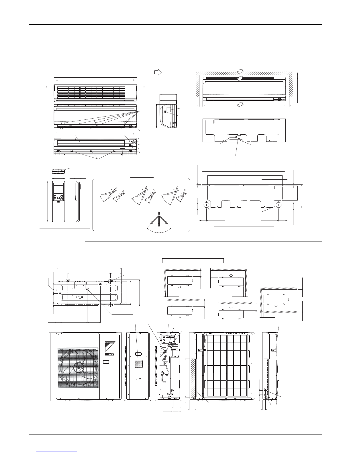
4. Dimensions
FTXS30/36HVJU
RKS30/36HVJU, RXS30/36HVJU
47-1/4 (1200mm)
7-3/8 (187mm)
1-3/16 (30mm) MIN
2-9/16 (65mm)
42-11/16 (1085mm)
1-15/16 (50mm) MIN
1-15/16 (50mm) MIN
9/16 (14.5mm)
9-1/2 (242mm)
11/16 (18mm)
9-7/16 (240mm)
45°
2-5/16 (58mm)
8-1/4 (210mm)
47-1/4 (1200mm)
5/8 (16mm)
1-3/8 (35.5mm)
45°
13-3/8 (340mm)
1-3/4 (45mm)
3-1/2 (89mm)
1-3/4 (45mm)
13-3/8 (340mm)
ROOM TEMP. THERMISTOR (INSIDE)
15°
OPERATION LAMP
φ3-1/8 (φ80mm) HOLE
WALL HOLE FOR EMBEDDED PIPING
MAINTENANCE)
(SPACE FOR
SIGNAL RECEIVER
FRONT GRILLE FIXTURES
WIRELESS REMOTE CONTROLLER
THE UNIT : ABOUT 15-3/4 (400mm))
(THE LENGTH OF PIPE OUTSIDE
GAS PIPE φ5/8 (φ15.9mm) CuT
30°
(AUTOMATIC)
UP/DOWN
PLATE
NAME
(AUTOMATIC)
RIGHT/LEFT
BLADE ANGLES
REAR
FLAPS
INTELLIGENT EYE LAMP
REQUIRED SPACE
75°
THE UNIT : ABOUT 18-1/8 (460mm))
(THE LENGTH OF PIPE OUTSIDE
LIQUID PIPE φ3/8 (φ9.5mm) CuT
RIGHT
PERFORMANCE)
(SPACE FOR
70°
60°
HEATINGFAN
BOTTOM
TERMINAL
WITH GROUND
BLOCK
TERMINAL
THE MARK (®) SHOWS PIPING DIRECTION
INDOOR UNIT ON/OFF SWITCH
40°
LEFT
(INSIDE)
SCREWS
FIXED
GRILLE
FRONT
70°
TRANSMITTER
SIGNAL
75°
STANDARD LOCATIONS OF WALL HOLES
AIR FLOW (INDOOR)
(
)
MOUNTING PLATE
INCLUDING
TIMER LAMP
COOLING, DRY
50°
INTELLIGENT EYE SENSOR
25°
MAINTENANCE)
(SPACE FOR
25°
15°
MODEL NAME PLATE
φ3-1/8 (φ80mm) HOLE
WALL HOLE
THE UNIT IS APPROX. 18-5/16 (465mm))
THE HOSE LENGTH OF OUTSIDE
O.D. φ11/16 (φ18mm)
I.D. φ9/16 (φ14mm)
(CONNECTING PART
DRAIN HOSE
3D062739A
MINIMUM SPACE FOR AIR PASSAGE
WALL HEIGHT ON AIR OUTLET SIDE = LESS THAN 47-1/4
37
24-7/16 6-5/16
4-CUTS FOR ANCHOR BOLTS
(M12)
2-11/16
2-5/8
3-15/16
13-3/4
3-15/16
1-15/16
1-15/16
5-15/16
12-5/8
13-3/4
14-15/16
(13-9/16~13-15/16)
DRAIN OUTLET
15/16
1-15/16
I.D.
φ15/16 HOSE FOR CONNECTION.
3-15/16
13-3/4
13-3/4
1-7/8 15-9/16 7-1/2
TERMINAL STRIP
GAS STOP VALVE
NAME PLATE
OUTDOOR AIR
THERMISTOR
LIQUID STOP VALVE
GROUND TERMINAL
38-15/16
22-1/4
2-3/16
GAS PIPE
(
φ5/8 SINGLE UNION)
3-15/16
INTERCONNECTING PIPING
AND WIRING INLET
3-1/16
LIQUID PIPE
(
φ3/8 SINGLE UNION)
3-5/16 1-11/16
3-1/2
1-15/16
3D063154A
Wiring Diagrams EDUS04-924A
8 Room Air Conditioners H-Series
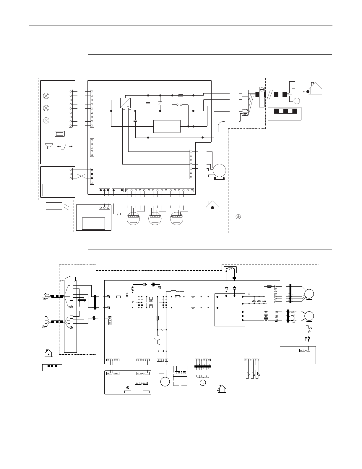
5. Wiring Diagrams
FTXS30/36HVJU
RKS30/36HVJU, RXS30/36HVJU
1
FU1
F1U
X1M
PCB1PCB3
S46S49
2
H1
BLK
11
BLK
1
LED1
H1P
3
BLK
3.15A
WHT
~
OUTDOOR
2
BLK
C102 V1
BLK
LED2
H2P
RED
3
H2
MR10
BLK
GRN
BLK
FIELD WIRING.
BLK
LED3
H3P
C101
BLK
H3
TRANSMISSION
CIRCUIT
99
BLK
CAUTION
FG
SW1
S21
NOTE THAT OPERATION WILL RESTART
AUTOMATICALLY IF THE MAIN POWER SUPPLY
IS TURNED OFF AND THEN BACK ON AGAIN.
BZ : BUZZER
C101, C102 : CAPACITOR
FG : FRAME GROUND
F1U : FUSE
H1P~H3P : PILOT LAMP
MR10 : MAGNETIC RELAY
M1F : FAN MOTOR
M1S~M3S : SWING MOTOR
PCB1~PCB4 : PRINTED CIRCUIT BOARD
R1T, R2T : THERMISTOR
S1~S49 : CONNECTOR
SW1 : OPERATION SWITCH
V1 : VARISTOR
X1M : TERMINAL STRIP
: PROTECTIVE GROUND
t°
S1
HA
7
RED
RTH1
R1T
BZ
4
BLU
S25
BLK
MS
3~
BRN
1
1
PCB4
BLK
ORG
S36
1
WHT
3
S41S47 S32
BLK
4
M1F
12
1
16 14 11173
1
8 1552213910 643
INTELLIGENT EYE
SENSOR
BLK
BLK
BLK
BLK
BLK
PNK
PNK
PNK
BLU
BLU
BLU
RED
RED
RED
ORG
ORG
ORG
YLW
YLW
YLW
S48PCB2
t°
1
3
WIRELESS
REMOTE
CONTROLLER
INDOOR
R2T
MSW MSWMSW
SIGNAL
RECEIVER
M1S M3SM2S
GRN
/
YLW
C: 3D060942C
L1R
GRN
Z6C
GRN
YLW
Z1C
X1M
Z8C
BLU
FU3
WHT
GRN
7
RED
M1F
E1
E2
HR2
SA2
HR1
MRM20
3.15A
POWER SUPPLY
V100
FU1
30A
MS
3~
MS
3~
V2
Z2C
AC1
BLU
MRM10
L
1
L1
BRN
6(P)
1
BRN
L2
L2
S70
+++
9
8
ORG
1
WHT
Z3C
7(N)
V9
AC2
2
Z5C
BLU
X11A
TO INDOOR UNIT
M1C
BLK
U
PM1
U
5
WHT
Z4C
X2M
V
V
4
FU2
3.15A
1
1
RED
W
W
3
2
RED
YLW
BLU
RED
YLW
BLU
S10
1
2
3
3
V3
Q1L
BLK
BLK
X12A
PCB1
MRC W
BLK
BLK
V5
S40
SHEET METAL
4
1
S90S51 S101 S80 S20
514151
616
1
indoor
Z7C
RED
BLU
GRY
BLK
GRN
BLU
BLU
BLU
BLU
BLU
BLK
RED
RED
WHT
FIELD WIRING
S80
41
RED
t˚t˚
BRN
ORGt˚BLU
WHT
YLW
151
S102
5
S52
IN CASE OF
COOLING
ONLY TYPE
R1T
PCB2
R2T
R3T
M
Y1R
S2
(OUTDOOR) (DISCHARGE)
(CONDENSER)
LED A
Y1E
SW4SW1
outdoor
Z1C~Z8C
X1M, X2M
Y1E
V2, V3, V5, V9, V100
SA2
FU1, FU2, FU3
AC1, AC2
U, V, W, X11A, X12A
E, E2
HR1, HR2
: FERRITE CORE
: TERMINAL STRIP
:
ELECTRONIC EXPANSION VALVE COIL
: VARISTOR
: SURGE ARRESTER
: FUSE
MRM10, MRM20
MRC/W
R1T~R3T
S2~S102
LEDA
M1C
M1F
L1R
Q1L
PM1
PCB1, 2
Y1R
SHEET METAL
: COMPRESSOR MOTOR
: FAN MOTOR
: REACTOR
: OVERLOAD PROTECTOR
: POWER MODULE
: PRINTED CIRCUIT BOARD
: REVERSING SOLENOID VALVE COIL
: TERMINAL STRIP FIXED PLATE
L
1, L2
SW1
SW4
: LIVE
:
FORCED OPERATION ON/OFF SW (SW1)
: LOCAL SETTING SW (SW4)
: MAGNETIC RELAY
: THERMISTOR
: CONNECTOR
: PILOT LAMP
: CONNECTOR
3D062017B
EDUS04-924A Piping Diagrams
Room Air Conditioners H-Series 9
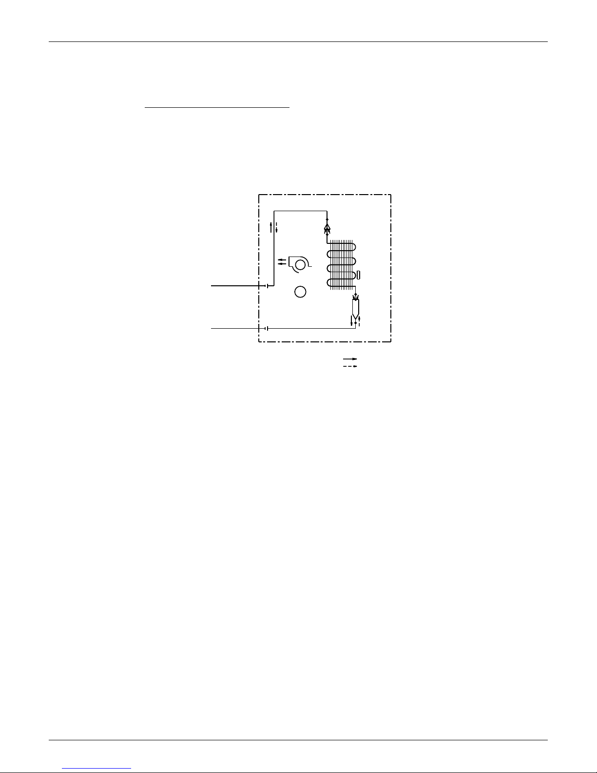
6. Piping Diagrams
6.1 Indoor Unit
FTXS30/36HVJU
CROSS FLOW FAN
ON HEAT EXCH.
THERMISTOR
HEAT EXCHANGER
1/2 CuT
5/8 CuT
HEADER
REFRIGERANT FLOW
INDOOR UNIT
HEATING
M
FIELD PIPING
COOLING
3/8 CuT
FAN MOTOR
FIELD PIPING
5/16 CuT
DISTRIBUTOR
4D062742
Piping Diagrams EDUS04-924A
10 Room Air Conditioners H-Series
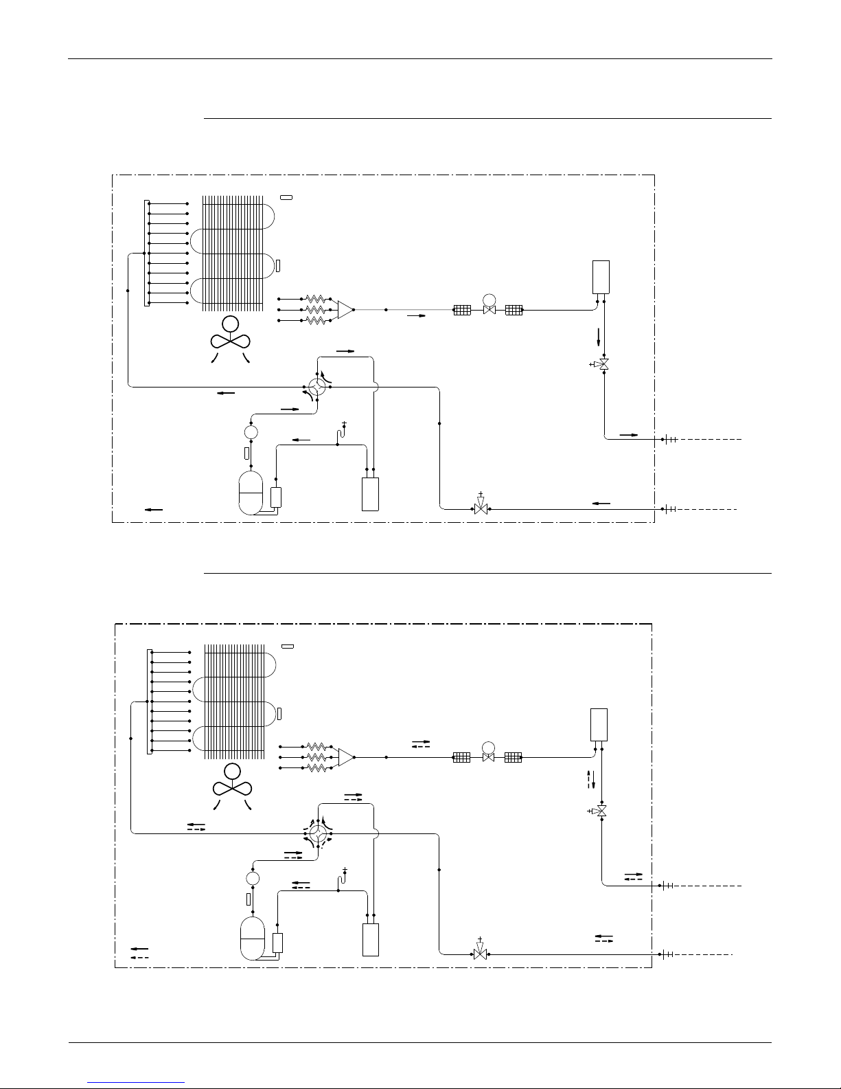
6.2 Outdoor Unit
RKS30/36HVJU
RXS30/36HVJU
OUTDOOR UNIT
HEAT EXCHANGER
OUTDOOR TEMPERATURE
THERMISTOR
HEADER
HEAT EXCHANGER(CONDENSER)
THERMISTOR
RECEIVER
1/2CuT
5/16CuT
3/8CuT
5/16CuT
5/16CuT
5/16CuT
5/16CuT
5/16CuT
5/16CuT
5/16CuT
5/16CuT
5/16CuT
5/16CuT
EV
5/16CuT
3/8CuT3/8CuT3/8CuT
5/16CuT
MOTOR
OPERATED
VALV E
FILTER FILTER
DISTRIBUTOR
DC FAN MOTOR
M
CAPILLARY TUBE
3/8CuT
PROPELLER FAN
4-WAY
VALV E
LIQUID LINE
STOP VALVE
5/8CuT 5/8CuT
FUSIBLE PLUG
3/8CuT
MUFFLER
1/4CuT
FIELD PIPING
LIQUID(3/8CuT)
3/8CuT
DISCHARGE PIPE
THERMISTOR
5/8CuT
5/8CuT
5/8CuT
5/16CuT
GAS LINE
STOP VALVE
REFRIGERANT FLOW
COOLING
COMPRESSOR
ACCUMULATOR ACCUMULATOR
FIELD PIPING
GAS(5/8CuT)
5/8CuT
3D071132A
EV
3/8CuT
3/8CuT
OUTDOOR TEMPERATURE
ACCUMULATOR
5/16CuT
HEAT EXCHANGER (CONDENSER)
STOP VALVE
FILTER
5/8CuT
STOP VALVE
DC FAN MOTOR
5/16CuT
ACCUMULATOR
PROPELLER FAN
5/16CuT
3/8CuT
LIQUID (3/8 CuT)
FIELD PIPING
5/8CuT
5/8CuT
HEAT EXCHANGER
3/8CuT
DISCHARGE PIPE
COOLING
FUSIBLE PLUG
ON:HEATING
VALV E
4-WAY
5/16CuT
5/16CuT
3/8CuT
5/16CuT
5/16CuT
5/16CuT
5/8CuT
5/16CuT
5/16CuT
5/16CuT
HEADER
3/8CuT
FILTER
THERMISTOR
VALV E
OPERATED
MOTOR
HEATING
REFRIGERANT FLOW
5/8CuT
THERMISTOR
1/4CuT
RECEIVER
5/16CuT
1/2CuT
DISTRIBUTOR
5/16CuT
GAS LINE
CAPILLARY TUBE
M
5/8CuT
COMPRESSOR
THERMISTOR
5/16CuT
MUFFLER
GAS (5/8 CuT)
FIELD PIPING
OUTDOOR UNIT
3/8CuT
LIQUID LINE
3D063153
EDUS04-924A Capacity Tables
Room Air Conditioners H-Series 11
7. Capacity Tables
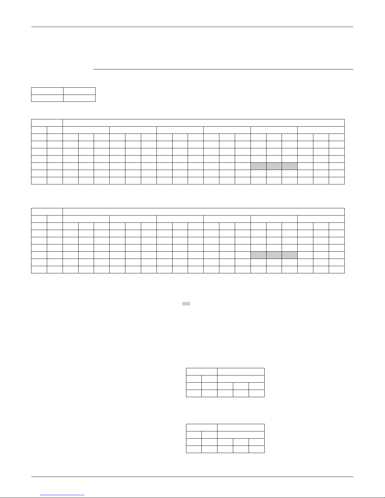
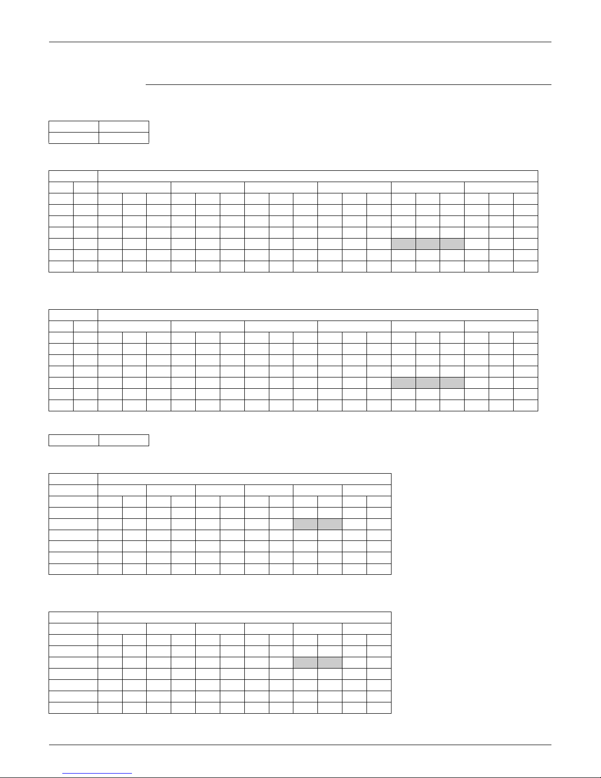
7.1 Cooling Only
FTXS30HVJU + RKS30HVJU (60 Hz, 230 V)
3D071130
AFR 20.0
BF 0.23
Temp: Celsius
TC, SHC, PI: kW
INDOOR OUTDOOR TEMPERATURE (°CDB)
EWB EDB 20.0 25.0 30.0 32.0 35.0 40.0
°C °C TC SHC PI TC SHC PI TC SHC PI TC SHC PI TC SHC PI TC SHC PI
14.0 20.0 6.92 4.97 1.38 6.92 4.97 1.61 6.92 4.97 1.88 6.92 4.97 2.00 6.92 4.97 2.20 6.92 4.97 2.46
16.0 22.0 8.63 5.59 1.85 8.63 5.59 2.18 8.60 5.58 2.57 8.44 5.49 2.66 8.19 5.37 2.78 7.78 5.16 2.81
18.0 25.0 9.83 6.19 2.17 9.42 5.99 2.38 9.01 5.78 2.59 8.84 5.70 2.67 8.60 5.59 2.79 8.19 5.39 2.82
19.4 26.7 10.03 6.43 2.18 9.62 6.23 2.39 9.21 6.04 2.59 9.05 5.96 2.68
8.80 5.84 2.80 8.39 5.66 2.83
22.030.010.646.172.2010.235.992.409.825.822.619.655.752.699.415.652.829.005.482.84
24.0 32.0 11.04 5.97 2.21 10.63 5.81 2.42 10.22 5.65 2.62 10.06 5.59 2.71 9.81 5.49 2.83 9.40 5.34 2.86
Temp: Fahrenheit
TC, SHC: kBtu/h
PI: kW
INDOOR OUTDOOR TEMPERATURE (°FDB)
EWB EDB 68.0 77.0 86.0 90.0 95.0 104.0
°F °F TC SHC PI TC SHC PI TC SHC PI TC SHC PI TC SHC PI TC SHC PI
57.2 68.0 23.61 16.97 1.38 23.61 16.97 1.61 23.61 16.97 1.88 23.61 16.97 2.00 23.61 16.97 2.20 23.61 16.97 2.46
60.8 71.6 29.44 19.09 1.85 29.44 19.09 2.18 29.35 19.04 2.57 28.79 18.75 2.66 27.95 18.31 2.78 26.55 17.61 2.81
64.4 77.0 33.53 21.13 2.17 32.13 20.43 2.38 30.73 19.74 2.59 30.17 19.47 2.67 29.33 19.06 2.79 27.94 18.40 2.82
67.0 80.0 34.22 21.94 2.18 32.82 21.26 2.39 31.42 20.59 2.59 30.86 20.33 2.68
30.00 19.94 2.80 28.63 19.30 2.83
71.6 86.0 36.29 21.04 2.20 34.90 20.43 2.40 33.50 19.84 2.61 32.94 19.61 2.69 32.10 19.26 2.82 30.70 18.69 2.84
75.2 89.6 37.68 20.37 2.21 36.28 19.82 2.42 34.88 19.28 2.62 34.32 19.06 2.71 33.48 18.74 2.83 32.09 18.22 2.86
Symbols: Note:
AFR : Airflow rate (m3/min.) 1. Ratings shown are net capacities which include a deduction for indoor fan
motor heat.
2. shows nominal (rated) capacities and power input.
3. TC, PI and SHC must be calculated by interpolation using the figures in
the tables. (Figures out of the tables should not be used for calculation.)
4. About SHC which are not mentioned on the table, please calculate them
with around values in direct proportion.
5. Capacities are based on the following conditions.
Corresponding refrigerant piping length : 25 ft
Level difference : 0 ft
6. Cooling capacity at –15°CDB and 5°FDB.
BF : Bypass factor
EWB : Entering wet bulb temp. (°C) / (°F)
EDB : Entering dry bulb temp. (°C) / (°F)
TC : Total capacity (kW) / (kBtu/h)
SHC : Sensible heating capacity (kW) / (kBtu/h)
PI : Power input (kW)
Temp: Celsius
TC, SHC, PI: kW
60 Hz, 208 - 230 V
INDOOR OUTDOOR
EWB EDB –15 (°CDB)
°C °C TC SHC PI
14.0 20.0 5.49 4.28 0.49
Temp: Fahrenheit
TC, SHC: kBtu/h
PI: kW
60 Hz, 208 - 230 V
INDOOR OUTDOOR
EWB EDB 5 (°FDB)
°F °F TC SHC PI
57.2 68.0 18.73 14.59 0.49
Capacity Tables EDUS04-924A
12 Room Air Conditioners H-Series
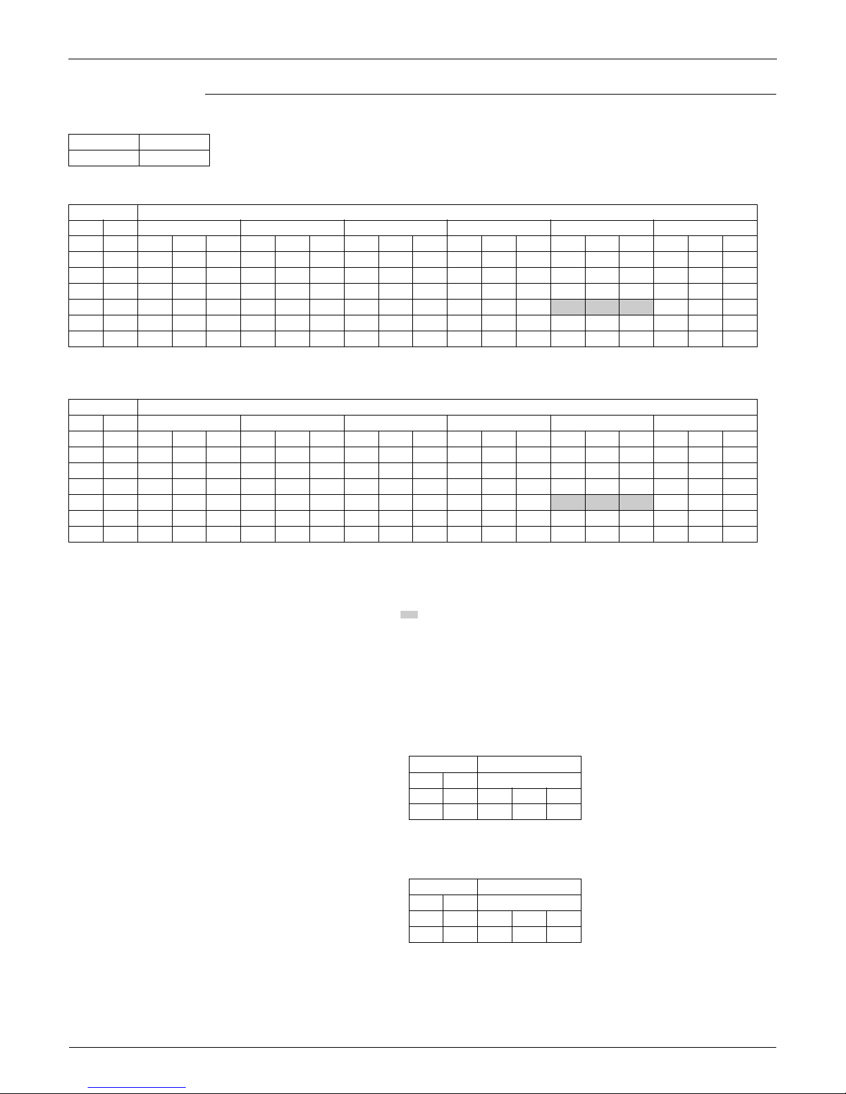
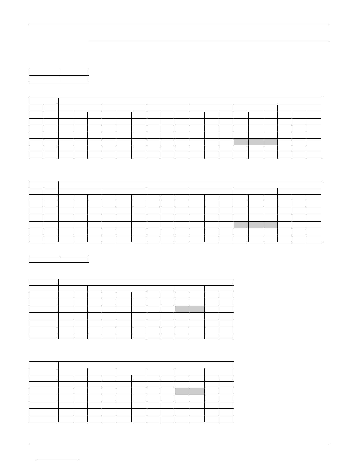
FTXS36HVJU + RKS36HVJU (60 Hz, 230 V)
3D071131
AFR 21.8
BF 0.27
Temp: Celsius
TC, SHC, PI: kW
INDOOR OUTDOOR TEMPERATURE (°CDB)
EWB EDB 20.0 25.0 30.0 32.0 35.0 40.0
°C °C TC SHC PI TC SHC PI TC SHC PI TC SHC PI TC SHC PI TC SHC PI
14.0 20.0 7.15 5.14 1.54 7.15 5.14 1.77 7.15 5.14 2.05 7.15 5.14 2.17 7.15 5.14 2.38 7.15 5.14 2.67
16.0 22.0 8.92 5.78 2.09 8.92 5.78 2.44 8.92 5.78 2.87 8.92 5.78 3.07 8.92 5.78 3.41 8.92 5.78 3.89
18.0 25.0 10.82 6.74 2.80 10.82 6.74 3.35 10.75 6.70 3.97 10.55 6.60 4.10 10.26 6.45 4.29 9.60 6.12 4.24
19.4 26.7 11.82 7.38 3.25 11.48 7.20 3.66 10.99 6.95 3.98 10.79 6.86 4.11
10.50 6.71 4.30 9.82 6.38 4.24
22.0 30.0 12.69 7.14 3.37 12.20 6.91 3.69 11.71 6.69 4.01 11.52 6.60 4.14 11.23 6.47 4.33 10.50 6.16 4.24
24.0 32.0 13.18 6.90 3.39 12.69 6.69 3.71 12.20 6.49 4.03 12.00 6.41 4.16 11.71 6.29 4.35 10.95 5.99 4.24
Temp: Fahrenheit
TC, SHC: kBtu/h
PI: kW
INDOOR OUTDOOR TEMPERATURE (°FDB)
EWB EDB 68.0 77.0 86.0 90.0 95.0 104.0
°F °F TC SHC PI TC SHC PI TC SHC PI TC SHC PI TC SHC PI TC SHC PI
57.2 68.0 24.39 17.54 1.54 24.39 17.54 1.77 24.39 17.54 2.05 24.39 17.54 2.17 24.39 17.54 2.38 24.39 17.54 2.67
60.8 71.6 30.43 19.72 2.09 30.43 19.72 2.44 30.43 19.72 2.87 30.43 19.72 3.07 30.43 19.72 3.41 30.43 19.72 3.89
64.4 77.0 36.91 23.00 2.80 36.91 23.00 3.35 36.67 22.87 3.97 36.00 22.52 4.10 35.00 22.01 4.29 32.75 20.89 4.24
67.0 80.0 40.33 25.18 3.25 39.16 24.57 3.66 37.49 23.72 3.98 36.83 23.39 4.11
36.00 22.89 4.30 33.52 21.78 4.24
71.6 86.0 43.31 24.36 3.37 41.64 23.58 3.69 39.97 22.83 4.01 39.30 22.53 4.14 38.30 22.09 4.33 35.82 21.01 4.24
75.2 89.6 44.96 23.54 3.39 43.29 22.83 3.71 41.62 22.14 4.03 40.95 21.86 4.16 39.95 21.46 4.35 37.35 20.43 4.24
Symbols: Note:
AFR : Airflow rate (m3/min.) 1. Ratings shown are net capacities which include a deduction for indoor fan
motor heat.
2. shows nominal (rated) capacities and power input.
3. TC, PI and SHC must be calculated by interpolation using the figures in
the tables. (Figures out of the tables should not be used for calculation.)
4. About SHC which are not mentioned on the table, please calculate them
with around values in direct proportion.
5. Capacities are based on the following conditions.
Corresponding refrigerant piping length : 25 ft
Level difference : 0 ft
6. Cooling capacity at –15°CDB and 5°FDB.
BF : Bypass factor
EWB : Entering wet bulb temp. (°C) / (°F)
EDB : Entering dry bulb temp. (°C) / (°F)
TC : Total capacity (kW) / (kBtu/h)
SHC : Sensible heating capacity (kW) / (kBtu/h)
PI : Power input (kW)
Temp: Celsius
TC, SHC, PI: kW
60 Hz, 208 - 230 V
INDOOR OUTDOOR
EWB EDB –15 (°CDB)
°C °C TC SHC PI
14.0 20.0 5.67 4.42 0.54
Temp: Fahrenheit
TC, SHC: kBtu/h
PI: kW
60 Hz, 208 - 230 V
INDOOR OUTDOOR
EWB EDB 5 (°FDB)
°F °F TC SHC PI
57.2 68.0 19.35 15.08 0.54
EDUS04-924A Capacity Tables
Room Air Conditioners H-Series 13
7.2 Heat Pump
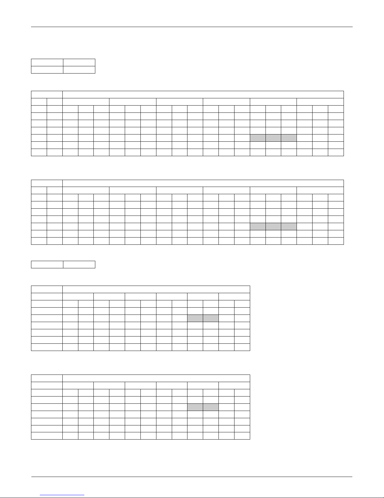
FTXS30HVJU + RXS30HVJU (60 Hz, 208 - 230 V)
Cooling
Heating
AFR 20.0
BF 0.23
Temp: Celsius
TC, SHC, PI: kW
INDOOR OUTDOOR TEMPERATURE (°CDB)
EWB EDB 20.0 25.0 30.0 32.0 35.0 40.0
°C °C TC SHC PI TC SHC PI TC SHC PI TC SHC PI TC SHC PI TC SHC PI
14.0 20.0 6.92 4.97 1.38 6.92 4.97 1.61 6.92 4.97 1.88 6.92 4.97 2.00 6.92 4.97 2.20 6.92 4.97 2.46
16.0 22.0 8.63 5.59 1.85 8.63 5.59 2.18 8.60 5.58 2.57 8.44 5.49 2.66 8.19 5.37 2.78 7.78 5.16 2.81
18.0 25.0 9.83 6.19 2.17 9.42 5.99 2.38 9.01 5.78 2.59 8.84 5.70 2.67 8.60 5.59 2.79 8.19 5.39 2.82
19.4 26.7 10.03 6.43 2.18 9.62 6.23 2.39 9.21 6.04 2.59 9.05 5.96 2.68
8.80 5.84 2.80 8.39 5.66 2.83
22.030.010.646.172.2010.235.992.409.825.822.619.655.752.699.415.652.829.005.482.84
24.0 32.0 11.04 5.97 2.21 10.63 5.81 2.42 10.22 5.65 2.62 10.06 5.59 2.71 9.81 5.49 2.83 9.40 5.34 2.86
Temp: Fahrenheit
TC, SHC: kBtu/h
PI: kW
INDOOR OUTDOOR TEMPERATURE (°FDB)
EWB EDB 68.0 77.0 86.0 90.0 95.0 104.0
°F °F TC SHC PI TC SHC PI TC SHC PI TC SHC PI TC SHC PI TC SHC PI
57.2 68.0 23.61 16.97 1.38 23.61 16.97 1.61 23.61 16.97 1.88 23.61 16.97 2.00 23.61 16.97 2.20 23.61 16.97 2.46
60.8 71.6 29.44 19.09 1.85 29.44 19.09 2.18 29.35 19.04 2.57 28.79 18.75 2.66 27.95 18.31 2.78 26.55 17.61 2.81
64.4 77.0 33.53 21.13 2.17 32.13 20.43 2.38 30.73 19.74 2.59 30.17 19.47 2.67 29.33 19.06 2.79 27.94 18.40 2.82
67.0 80.0 34.22 21.94 2.18 32.82 21.26 2.39 31.42 20.59 2.59 30.86 20.33 2.68
30.00 19.94 2.80 28.63 19.30 2.83
71.6 86.0 36.29 21.04 2.20 34.90 20.43 2.40 33.50 19.84 2.61 32.94 19.61 2.69 32.10 19.26 2.82 30.70 18.69 2.84
75.2 89.6 37.68 20.37 2.21 36.28 19.82 2.42 34.88 19.28 2.62 34.32 19.06 2.71 33.48 18.74 2.83 32.09 18.22 2.86
AFR 20.1
Temp: Celsius
TC, PI: kW
INDOOR OUTDOOR TEMPERATURE (°CWB)
EDB –15.0 –10.0 –5.0 0 6.0 10.0
°C TC PI TC PI TC PI TC PI TC PI TC PI
15.0 4.86 2.51 6.17 2.68 6.82 2.77 9.17 3.62 10.55 3.81 11.47 3.94
21.1 4.56 2.58 5.87 2.75 6.52 2.84 8.82 3.71
10.20 3.90 10.69 3.70
22.0 4.44 2.61 5.75 2.78 6.40 2.87 8.68 3.74 10.01 3.89 10.01 3.34
24.0 4.32 2.64 5.63 2.81 6.28 2.89 8.54 3.78 9.33 3.49 9.33 3.01
25.0 4.26 2.65 5.57 2.82 6.22 2.91 8.47 3.80 8.99 3.30 8.99 2.86
27.0 4.14 2.68 5.45 2.85 6.10 2.94 8.31 3.82 8.31 2.94 8.31 2.56
Temp: Fahrenheit
TC: kBtu/h
PI: kW
INDOOR OUTDOOR TEMPERATURE (°FWB)
EDB 5.0 14.0 23.0 32.0 43.0 50.0
°F TC PI TC PI TC PI TC PI TC PI TC PI
59.0 16.57 2.51 21.05 2.68 23.25 2.77 31.29 3.62 36.00 3.81 39.15 3.94
70.0 15.55 2.58 20.03 2.75 22.23 2.84 30.09 3.71
34.80 3.90 36.46 3.70
71.6 15.14 2.61 19.62 2.78 21.82 2.87 29.61 3.74 34.15 3.89 34.15 3.34
75.2 14.74 2.64 19.21 2.81 21.42 2.89 29.13 3.78 31.83 3.49 31.83 3.01
77.0 14.53 2.65 19.01 2.82 21.21 2.91 28.89 3.80 30.67 3.30 30.67 2.86
80.6 14.12 2.68 18.60 2.85 20.80 2.94 28.36 3.82 28.36 2.94 28.36 2.56
Capacity Tables EDUS04-924A
14 Room Air Conditioners H-Series
3D063318
Symbols: Note:
AFR : Airflow rate (m3/min.) 1. Ratings shown are net capacities which include a deduction for indoor fan
motor heat.
2. shows nominal (rated) capacities and power input.
3. TC, PI and SHC must be calculated by interpolation using the figures in
the tables. (Figures out of the tables should not be used for calculation.)
4. About SHC which are not mentioned on the table, please calculate them
with around values in direct proportion.
5. Capacities are based on the following conditions.
Corresponding refrigerant piping length : 25 ft
Level difference : 0 ft
6. Cooling capacity at –15°CDB and 5°FDB.
BF : Bypass factor
EWB : Entering wet bulb temp. (°C) / (°F)
EDB : Entering dry bulb temp. (°C) / (°F)
TC : Total capacity (kW) / (kBtu/h)
SHC : Sensible heating capacity (kW) / (kBtu/h)
PI : Power input (kW)
Temp: Celsius
TC, SHC, PI: kW
60 Hz, 208 - 230 V
INDOOR OUTDOOR
EWB EDB –15 (°CDB)
°C °C TC SHC PI
14.0 20.0 5.49 4.28 0.49
Temp: Fahrenheit
TC, SHC: kBtu/h
PI: kW
60 Hz, 208 - 230 V
INDOOR OUTDOOR
EWB EDB 5 (°FDB)
°F °F TC SHC PI
57.2 68.0 18.73 14.59 0.49
EDUS04-924A Capacity Tables
Room Air Conditioners H-Series 15
FTXS36HVJU + RXS36HVJU
<60 Hz, 208 V>
Cooling
Heating
AFR 21.8
BF 0.27
Temp: Celsius
TC, SHC, PI: kW
INDOOR OUTDOOR TEMPERATURE (°CDB)
EWB EDB 20.0 25.0 30.0 32.0 35.0 40.0
°C °C TC SHC PI TC SHC PI TC SHC PI TC SHC PI TC SHC PI TC SHC PI
14.0 20.0 7.15 5.14 1.53 7.15 5.14 1.77 7.15 5.14 2.05 7.15 5.14 2.17 7.15 5.14 2.38 7.15 5.14 2.67
16.0 22.0 8.92 5.78 2.07 8.92 5.78 2.43 8.92 5.78 2.86 8.92 5.78 3.07 8.92 5.78 3.42 8.66 5.65 3.83
18.0 25.0 10.82 6.74 2.78 10.82 6.74 3.33 10.44 6.54 3.70 10.25 6.45 3.81 9.97 6.30 3.99 9.10 5.88 3.83
19.4 26.7 11.62 7.28 3.11 11.15 7.03 3.41 10.67 6.80 3.70 10.48 6.70 3.82
10.20 6.56 4.00 9.32 6.14 3.83
22.0 30.0 12.33 6.97 3.14 11.85 6.75 3.44 11.38 6.54 3.73 11.19 6.46 3.85 10.90 6.33 4.03 9.98 5.94 3.83
24.0 32.0 12.80 6.74 3.16 12.32 6.54 3.45 11.85 6.35 3.75 11.66 6.27 3.87 11.37 6.15 4.04 10.41 5.78 3.83
Temp: Fahrenheit
TC, SHC: kBtu/h
PI: kW
INDOOR OUTDOOR TEMPERATURE (°FDB)
EWB EDB 68.0 77.0 86.0 90.0 95.0 104.0
°F °F TC SHC PI TC SHC PI TC SHC PI TC SHC PI TC SHC PI TC SHC PI
57.2 68.0 24.39 17.54 1.53 24.39 17.54 1.77 24.39 17.54 2.05 24.39 17.54 2.17 24.39 17.54 2.38 24.39 17.54 2.67
60.8 71.6 30.43 19.72 2.07 30.43 19.72 2.43 30.43 19.72 2.86 30.43 19.72 3.07 30.43 19.72 3.42 29.55 19.27 3.83
64.4 77.0 36.91 23.00 2.78 36.91 23.00 3.33 35.62 22.33 3.70 34.97 22.00 3.81 34.00 21.51 3.99 31.05 20.05 3.83
67.0 80.0 39.66 24.83 3.11 38.04 24.00 3.41 36.42 23.19 3.70 35.77 22.87 3.82
35.00 22.39 4.00 31.79 20.96 3.83
71.6 86.0 42.07 23.78 3.14 40.45 23.04 3.44 38.83 22.32 3.73 38.18 22.03 3.85 37.21 21.61 4.03 34.04 20.26 3.83
75.2 89.6 43.67 23.00 3.16 42.05 22.32 3.45 40.43 21.65 3.75 39.78 21.39 3.87 38.81 21.00 4.04 35.53 19.72 3.83
AFR 22.9
Temp: Celsius
TC, PI: kW
INDOOR OUTDOOR TEMPERATURE (°CWB)
EDB –15.0 –10.0 –5.0 0 6.0 10.0
°C TC PI TC PI TC PI TC PI TC PI TC PI
15.0 5.00 2.45 6.01 2.57 7.02 2.70 9.44 3.53 10.86 3.71 11.81 3.84
21.1 4.69 2.51 5.70 2.64 6.71 2.76 9.08 3.61
10.50 3.80 11.45 3.93
22.0 4.57 2.54 5.58 2.67 6.58 2.79 8.93 3.65 10.36 3.83 11.30 3.96
24.0 4.45 2.57 5.45 2.69 6.46 2.82 8.79 3.68 10.21 3.87 11.16 3.99
25.0 4.38 2.58 5.39 2.71 6.40 2.83 8.71 3.70 10.14 3.89 10.97 3.92
27.0 4.26 2.61 5.27 2.74 6.28 2.86 8.57 3.73 9.99 3.92 10.15 3.45
Temp: Fahrenheit
TC: kBtu/h
PI: kW
INDOOR OUTDOOR TEMPERATURE (°FWB)
EDB 5.0 14.0 23.0 32.0 43.0 50.0
°F TC PI TC PI TC PI TC PI TC PI TC PI
59.0 17.06 2.45 20.50 2.57 23.94 2.70 32.21 3.53 37.06 3.71 40.30 3.84
70.0 16.01 2.51 19.45 2.64 22.89 2.76 30.97 3.61
36.00 3.80 39.06 3.93
71.6 15.59 2.54 19.03 2.67 22.47 2.79 30.48 3.65 35.33 3.83 38.57 3.96
75.2 15.17 2.57 18.61 2.69 22.05 2.82 29.98 3.68 34.84 3.87 38.07 3.99
77.0 14.96 2.58 18.40 2.71 21.84 2.83 29.73 3.70 34.59 3.89 37.44 3.92
80.6 14.54 2.61 17.98 2.74 21.42 2.86 29.24 3.73 34.09 3.92 34.62 3.45
Capacity Tables EDUS04-924A
16 Room Air Conditioners H-Series
<60 Hz, 230 V>
Cooling
Heating
AFR 21.8
BF 0.27
Temp: Celsius
TC, SHC, PI: kW
INDOOR OUTDOOR TEMPERATURE (°CDB)
EWB EDB 20.0 25.0 30.0 32.0 35.0 40.0
°C °C TC SHC PI TC SHC PI TC SHC PI TC SHC PI TC SHC PI TC SHC PI
14.0 20.0 7.15 5.14 1.54 7.15 5.14 1.77 7.15 5.14 2.05 7.15 5.14 2.17 7.15 5.14 2.38 7.15 5.14 2.67
16.0 22.0 8.92 5.78 2.09 8.92 5.78 2.44 8.92 5.78 2.87 8.92 5.78 3.07 8.92 5.78 3.41 8.92 5.78 3.89
18.0 25.0 10.82 6.74 2.80 10.82 6.74 3.35 10.75 6.70 3.97 10.55 6.60 4.10 10.26 6.45 4.29 9.60 6.12 4.24
19.4 26.7 11.82 7.38 3.25 11.48 7.20 3.66 10.99 6.95 3.98 10.79 6.86 4.11
10.50 6.71 4.30 9.82 6.38 4.24
22.0 30.0 12.69 7.14 3.37 12.20 6.91 3.69 11.71 6.69 4.01 11.52 6.60 4.14 11.23 6.47 4.33 10.50 6.16 4.24
24.0 32.0 13.18 6.90 3.39 12.69 6.69 3.71 12.20 6.49 4.03 12.00 6.41 4.16 11.71 6.29 4.35 10.95 5.99 4.24
Temp: Fahrenheit
TC, SHC: kBtu/h
PI: kW
INDOOR OUTDOOR TEMPERATURE (°FDB)
EWB EDB 68.0 77.0 86.0 89.6 95.0 104.0
°F °F TC SHC PI TC SHC PI TC SHC PI TC SHC PI TC SHC PI TC SHC PI
57.2 68.0 24.39 17.54 1.54 24.39 17.54 1.77 24.39 17.54 2.05 24.39 17.54 2.17 24.39 17.54 2.38 24.39 17.54 2.67
60.8 71.6 30.43 19.72 2.09 30.43 19.72 2.44 30.43 19.72 2.87 30.43 19.72 3.07 30.43 19.72 3.41 30.43 19.72 3.89
64.4 77.0 36.91 23.00 2.80 36.91 23.00 3.35 36.67 22.87 3.97 36.00 22.52 4.10 35.00 22.01 4.29 32.75 20.89 4.24
67.0 80.0 40.33 25.18 3.25 39.16 24.57 3.66 37.49 23.72 3.98 36.83 23.39 4.11
36.00 22.89 4.30 33.52 21.78 4.24
71.6 86.0 43.31 24.36 3.37 41.64 23.58 3.69 39.97 22.83 4.01 39.30 22.53 4.14 38.30 22.09 4.33 35.82 21.01 4.24
75.2 89.6 44.96 23.54 3.39 43.29 22.83 3.71 41.62 22.14 4.03 40.95 21.86 4.16 39.95 21.46 4.35 37.35 20.43 4.24
AFR 22.9
Temp: Celsius
TC, PI: kW
INDOOR OUTDOOR TEMPERATURE (°CWB)
EDB –15.0 –10.0 –5.0 0 6.0 10.0
°C TC PI TC PI TC PI TC PI TC PI TC PI
15.0 5.29 2.70 6.35 2.84 7.42 2.98 9.98 3.90 11.48 4.11 12.49 4.24
21.1 4.96 2.78 6.03 2.92 7.09 3.06 9.60 3.99
11.10 4.20 12.10 4.34
22.0 4.83 2.81 5.90 2.95 6.96 3.09 9.44 4.03 10.95 4.24 11.95 4.38
24.0 4.70 2.84 5.77 2.98 6.83 3.12 9.29 4.07 10.79 4.28 11.39 4.08
25.0 4.63 2.85 5.70 2.99 6.77 3.13 9.21 4.09 10.72 4.29 10.97 3.83
27.0 4.50 2.88 5.57 3.02 6.64 3.16 9.06 4.12 10.15 3.96 10.15 3.37
Temp: Fahrenheit
TC: kBtu/h
PI: kW
INDOOR OUTDOOR TEMPERATURE (°FWB)
EDB 5.0 14.0 23.0 32.0 43.0 50.0
°F TC PI TC PI TC PI TC PI TC PI TC PI
59.0 18.04 2.70 21.67 2.84 25.31 2.98 34.05 3.90 39.18 4.11 42.60 4.24
70.0 16.92 2.78 20.56 2.92 24.20 3.06 32.74 3.99
38.00 4.20 41.29 4.34
71.6 16.48 2.81 20.12 2.95 23.75 3.09 32.22 4.03 37.35 4.24 40.77 4.38
75.2 16.04 2.84 19.67 2.98 23.31 3.12 31.70 4.07 36.83 4.28 38.86 4.08
77.0 15.81 2.85 19.45 2.99 23.08 3.13 31.43 4.09 36.57 4.29 37.44 3.83
80.6 15.37 2.88 19.00 3.02 22.64 3.16 30.91 4.12 34.62 3.96 34.62 3.37

EDUS04-924A Capacity Tables
Room Air Conditioners H-Series 17
3D063319
Symbols: Note:
AFR : Airflow rate (m3/min.) 1. Ratings shown are net capacities which include a deduction for indoor fan
motor heat.
2. shows nominal (rated) capacities and power input.
3. TC, PI and SHC must be calculated by interpolation using the figures in
the tables. (Figures out of the tables should not be used for calculation.)
4. About SHC which are not mentioned on the table, please calculate them
with around values in direct proportion.
5. Capacities are based on the following conditions.
Corresponding refrigerant piping length : 25 ft
Level difference : 0 ft
6. Cooling capacity at –15°CDB and 5°FDB.
BF : Bypass factor
EWB : Entering wet bulb temp. (°C) / (°F)
EDB : Entering dry bulb temp. (°C) / (°F)
TC : Total capacity (kW) / (kBtu/h)
SHC : Sensible heating capacity (kW) / (kBtu/h)
PI : Power input (kW)
Temp: Celsius
TC, SHC, PI: kW
60 Hz, 208 - 230 V
INDOOR OUTDOOR
EWB EDB –15 (°CDB)
°C °C TC SHC PI
14.0 20.0 5.67 4.42 0.54
Temp: Fahrenheit
TC, SHC: kBtu/h
PI: kW
60 Hz, 208 - 230 V
INDOOR OUTDOOR
EWB EDB 5 (°FDB)
°F °F TC SHC PI
57.2 68.0 19.35 15.08 0.54
Capacity Tables EDUS04-924A
18 Room Air Conditioners H-Series
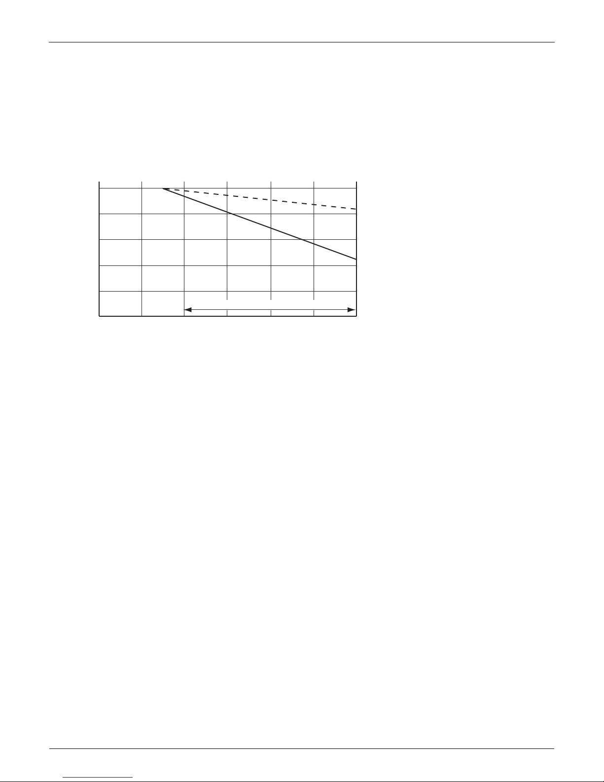
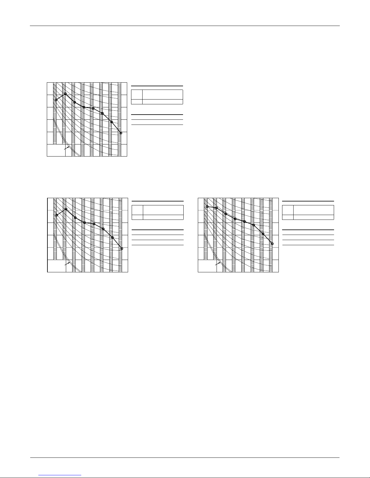
7.3 Capacity correction factor by the length of refrigerant piping (Reference)
The cooling capacity and the heating capacity of the unit have to be corrected in accordance with the length of refrigerant piping — the
distance between the indoor unit and the outdoor unit.
Note: The graph shows the factor when additional refrigerant of the proper quantity is charged.
<— line : cooling capacity>
<--- line : heating capacity>
Capacity correction factor
1
16.4 32.8 49.2 65.6 82.0 98.4
0.9
0.8
R-410A (30/36 class)
Piping length (ft)
(R4981)
Range of the Refrigerant Additional Charge
EDUS04-924A Operation Limit
Room Air Conditioners H-Series 19
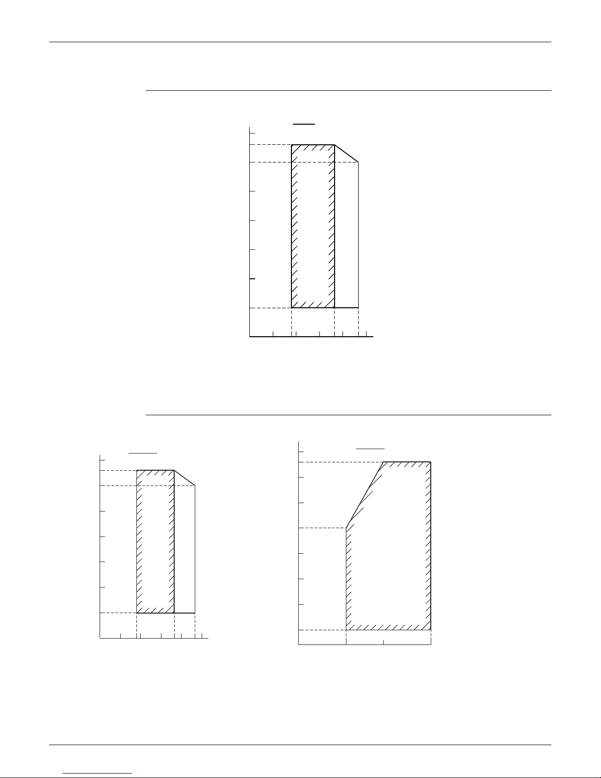
8. Operation Limit
RKS30/36HVJU
RXS30/36HVJU
Cooling
122
114.8
104
86
68
50
Outdoor temp.(˚FDB)
Pull-down period
Continuous operation
32
14
57.2 73.4 82.468 8650
Indoor temp.(˚FWB)
Notes:
The graphs are based
on the following conditions.
· Equivalent piping length 25ft
· Level difference 0m
· Air flow rate High
4D071134
68
· Equivalent piping length
on the following conditions.
The graphs are based
32
Continuous operation
· Air flow rate
14
86
Indoor temp. (°FDB)
77
Heating
Pull-down period
68
25ft
Indoor temp. (°FWB)
41
122
0m
23
Cooling
(5°FDB)
86
50
14
114.8
68
· Level difference
Notes:
75
32
Outdoor temp. (°FWB)
73.4
50
High
68
50
50
86
104
57.2
Outdoor temp. (°FDB)
82.4
Continuous operation
5
3D063168
NOTE: Operation can be extended to 0°F in cooling &
heating with use of the optional wind baffle.
NOTE:
Operation can be extended to
0°F in cooling with use of the
optional wind baffle.
Sound Level EDUS04-924A
20 Room Air Conditioners H-Series
9. Sound Level
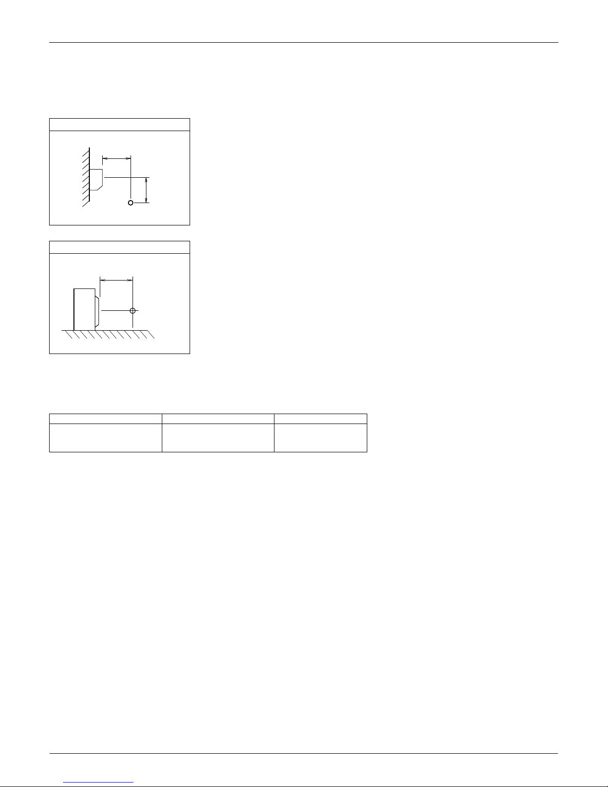
9.1 Measuring Location
Note:
1. Operation sound is measured in an anechoic chamber.
2. The data are based on the conditions shown in the table below.
Indoor Unit
Single Split Duct-Free System
Outdoor Unit
Cooling Heating Piping Length
Indoor ; 80°FDB / 67°FWB
Outdoor ; 95°FDB / 75°FWB
Indoor ; 70°FDB / 60°FWB
Outdoor ; 47°FDB / 43°FWB
16.4 ft
3.3 ft
2.6 ft
(R5162)
3.3 ft
(R4796)
EDUS04-924A Sound Level
Room Air Conditioners H-Series 21
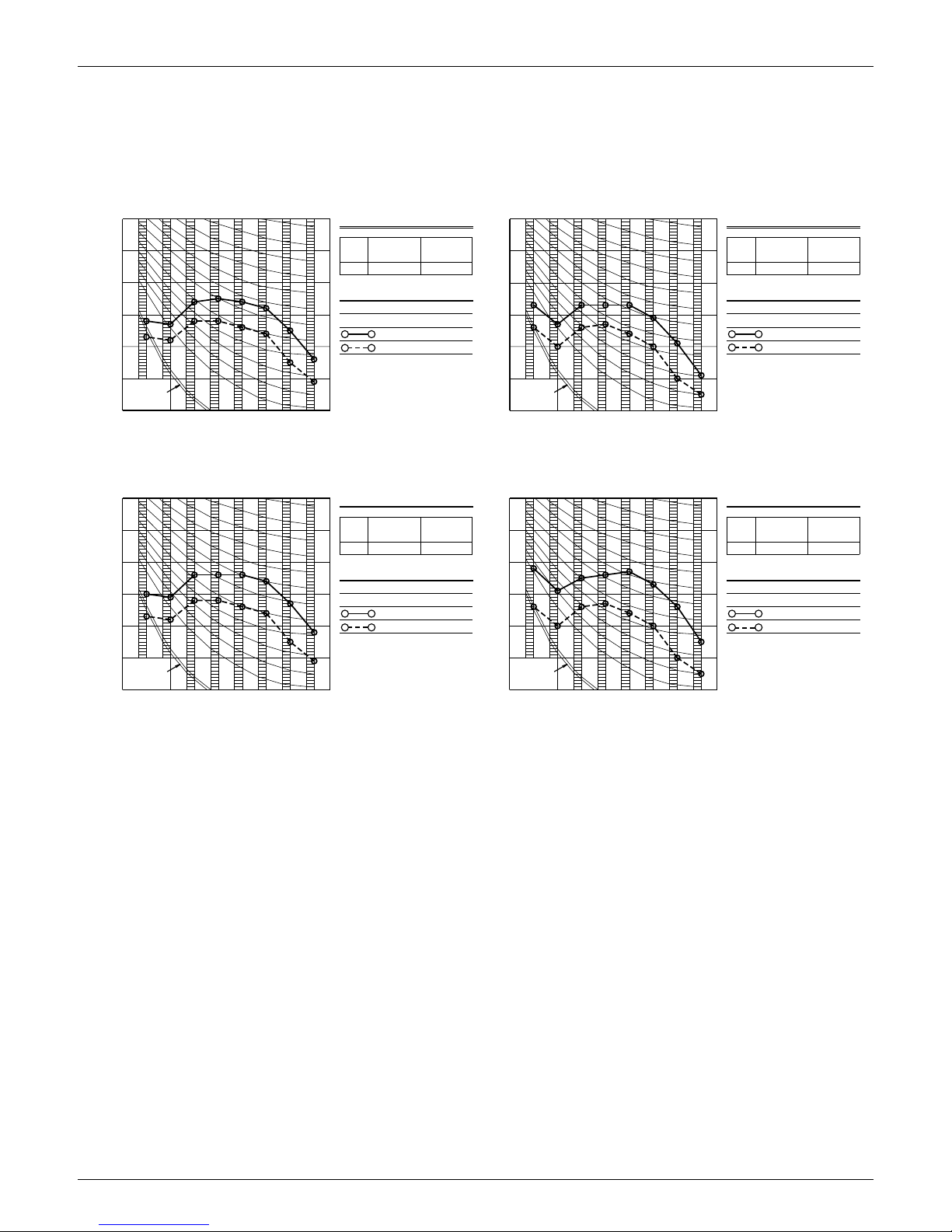
9.2 Octave Band Level
9.2.1 Indoor Unit
FTXS30HVJU
FTXS36HVJU
POWER SOURCE
JIS STANDARD
OPERATING CONDITIONS
OCTAVE BAND SOUND PRESSURE LEVEL
dB
(
0dB=0.0002
μ
bar
)
70
60
20
30
50
40
THRESHOLD HEARING
APPROXIMATE
FOR CONTINUOUS
NOISE
63 125
OCTAVE BAND CENTER FREQUENCY (Hz
)
250 500 1000 2000 4000 8000
OVER ALL ( dB )
SCALE
A
(
B.G.N IS ALREADY RECTIFIED
)
70
60
20
30
50
40
63
OCTAVE BAND CENTER FREQUENCY (Hz
)
125 250 500 1000 2000 4000 8000
OCTAVE BAND SOUND PRESSURE LEVEL
dB
(
0dB=0.0002
μ
bar
)
THRESHOLD HEARING
APPROXIMATE
FOR CONTINUOUS
NOISE
POWER SOURCE
JIS STANDARD
OPERATING CONDITIONS
OVER ALL ( dB )
SCALE
A
(
B.G.N IS ALREADY RECTIFIED
)
COOLING HEATING
NC-60
NC-30
NC-40
NC-20
NC-50
NC-30
NC-50
NC-60
NC-40
NC-20
60Hz
60Hz
208/230V
208/230V
(H)
(L)
47 40
60Hz
60Hz
208/230V
208/230V
(H)
(L)
47 38
208/230V 60Hz 208/230V 60Hz
60Hz 208/230V (H)
60Hz 208/230V (L)
Cooling
60Hz 208/230V (H)
60Hz 208/230V (L)
Heating
3D062991
POWER SOURCE
JIS STANDARD
OPERATING CONDITIONS
OCTAVE BAND SOUND PRESSURE LEVEL
dB
(
0dB=0.0002
μ
bar
)
70
60
20
30
50
40
THRESHOLD HEARING
APPROXIMATE
FOR CONTINUOUS
NOISE
63 125
OCTAVE BAND CENTER FREQUENCY (Hz
)
250 500 1000 2000 4000 8000
OVER ALL ( dB )
SCALE
A
(
B.G.N IS ALREADY RECTIFIED
)
70
60
20
30
50
40
63
OCTAVE BAND CENTER FREQUENCY (Hz
)
125 250 500 1000 2000 4000 8000
OCTAVE BAND SOUND PRESSURE LEVEL
dB
(
0dB=0.0002
μ
bar
)
THRESHOLD HEARING
APPROXIMATE
FOR CONTINUOUS
NOISE
POWER SOURCE
JIS STANDARD
OPERATING CONDITIONS
OVER ALL ( dB )
SCALE
A
(
B.G.N IS ALREADY RECTIFIED
)
COOLING HEATING
NC-60
NC-40
NC-30
NC-50
NC-20
NC-50
NC-40
NC-20
NC-30
NC-60
60Hz
60Hz
208/230V
208/230V
(H)
(L)
49 40
208/230V 60Hz
60Hz 208/230V (H)
60Hz 208/230V (L)
Cooling
60Hz
60Hz
208/230V
208/230V
(H)
(L)
49 38
208/230V 60Hz
60Hz 208/230V (H)
60Hz 208/230V (L)
Heating
3D062992
Sound Level EDUS04-924A
22 Room Air Conditioners H-Series
9.2.2 Outdoor Unit
RKS30/36HVJU
RXS30/36HVJU
POWER SOURCE
JIS STANDARD(JIS9612)
OPERATING CONDITIONS
OCTAVE BAND SOUND PRESSURE LEVEL
dB
(
0dB=0.0002
μ
bar
)
70
60
20
30
50
40
THRESHOLD HEARING
APPROXIMATE
FOR CONTINUOUS
NOISE
63 125
OCTAVE BAND CENTER FREQUENCY (Hz
)
250 500 1000 2000 4000 8000
OVER ALL ( dB )
SCALE
A
(
B.G.N IS ALREADY RECTIFIED
)
COOLING
208V-230V60Hz
54
208-230V 60Hz
Cooling
NC-60
NC-50
NC-40
NC-30
NC-20
4D071133
Heating
Cooling
208-230V 60Hz
NC-50
60Hz 208V-230V
NC-40
54
NC-20
NC-50
NC-30
NC-60
NC-30
NC-40
NC-60
NC-20
POWER SOURCE
JIS STANDARD(JIS9612)
OPERATING CONDITIONS
OCTAVE BAND SOUND PRESSURE LEVEL
dB
(
0dB=0.0002
μ
bar
)
70
60
20
30
50
40
THRESHOLD HEARING
APPROXIMATE
FOR CONTINUOUS
NOISE
63 125
OCTAVE BAND CENTER FREQUENCY (Hz
)
250 500 1000 2000 4000 8000
OVER ALL ( dB )
SCALE
A
(
B.G.N IS ALREADY RECTIFIED
)
70
60
20
30
50
40
63
OCTAVE BAND CENTER FREQUENCY (Hz
)
125 250 500 1000 2000 4000 8000
OCTAVE BAND SOUND PRESSURE LEVEL
dB
(
0dB=0.0002
μ
bar
)
THRESHOLD HEARING
APPROXIMATE
FOR CONTINUOUS
NOISE
POWER SOURCE
JIS STANDARD(JIS9612)
OPERATING CONDITIONS
OVER ALL ( dB )
SCALE
A
(
B.G.N IS ALREADY RECTIFIED
)
COOLING HEATING
60Hz 208V-230V
55
208-230V 60Hz
3D063288

EDUS04-924A Electric Characteristics
Room Air Conditioners H-Series 23
10.Electric Characteristics
3D063167
3D071271
Indoor Unit Outdoor Unit
Power Supply COMP OFM IFM
Hz - Volts Voltage Range MCA MOP RHz RLA W FLA W FLA
FTXS30HVJU
RKS30HVJU
RXS30HVJU
60 - 208
MAX. 60 Hz, 253 V
MIN. 60 Hz, 187 V
19.5 20 66
13.5
200
0.39
64
0.27
60 - 230 12.2 0.35 0.24
FTXS36HVJU
RKS36HVJU
RXS36HVJU
60 - 208
MAX. 60 Hz, 253 V
MIN. 60 Hz, 187 V
19.5 20
84 18.9
200
0.39
64
0.27
60 - 230 90 18.4 0.35 0.24
Symbols: Notes:
MCA : Min. circuit amps (A) 1. RLA is based on the following conditions.
Indoor temp. : 80°FDB / 67°FWB (26.7°CDB / 19.4°CWB)
Outdoor temp. : 95°FDB (35°CDB)
2. Maximum allowable voltage variation between phases is 2%.
3. Select wire size based on the larger value of MCA.
MOP : Max. overcurrent protection (A)
RHz : Rated operating frequency (Hz)
RLA : Rated load amps (A)
OFM : Outdoor fan motor
IFM : Indoor fan motor
W : Fan motor rated output (W)
FLA : Full load amps (A)

Installation Manual EDUS04-924A
24 Room Air Conditioners H-Series
11.Installation Manual
11.1 Indoor Unit
Read these SAFETY CONSIDERATIONS for Installation carefully
before installing an air conditioner or heat pump. After completing the
installation, make sure that the unit operates properly during the
startup operation.
Instruct the customer on how to operate and maintain the unit. Inform
customers that they should store this Installation Manual with the
Operation Manual for future reference.
Always use a licensed installer or contractor to install this product.
Improper installation can result in water or refrigerant leakage,
electrical shock, fire, or explosion.
Meanings of DANGER, WARNING, CAUTION, and NOTE Symbols:
DANGER .......... Indicates an imminently hazardous
situation which, if not avoided, will
result in death or serious injury.
WARNING ......... Indicates a potentially hazardous
situation which, if not avoided, could
result in death or serious injury.
CAUTION .......... Indicates a potentially hazardous
situation which, if not avoided, may
result in minor or moderate injury. It
may also be used to alert against
unsafe practices.
NOTE ................ Indicates situations that may result in
equipment or property-damage
accidents only.
• Refrigerant gas is heavier than air and replaces oxygen.
A massive leak can lead to oxygen depletion, especially
in basements, and an asphyxiation hazard could occur
leading to serious injury or death.
• Do not ground units to water pipes, gas pipes,
telephone wires, or lightning rods as incomplete
grounding can cause a severe shock hazard resulting
in severe injury or death. Additionally, grounding to
gas pipes could cause a gas leak and potential
explosion causing severe injury or death.
• If refrigerant gas leaks during installation, ventilate
the area immediately. Refrigerant gas may produce
toxic gas if it comes into contact with fire. Exposure to
this gas could cause severe injury or death.
• After completing the installation work, check that the
refrigerant gas does not leak throughout the system.
• Do not install unit in an area where flammable
materials are present due to risk of explosions that
can cause serious injury or death.
• Safely dispose all packing and transportation
materials in accordance with federal/state/local laws
or ordinances. Packing materials such as nails and
other metal or wood parts, including plastic packing
materials used for transportation may cause injuries
or death by suffocation.
• Only qualified personnel must carry out the installation
work. Installation must be done in accordance with this
installation manual. Improper installation may result in
water leakage, electric shock, or fire.
• When installing the unit in a small room, take measures
to keep the refrigerant concentration from exceeding
allowable safety limits. Excessive refrigerant leaks, in
the event of an accident in a closed ambient space, can
lead to oxygen deficiency.
• Use only specified accessories and parts for
installation work. Failure to use specified parts may
result in water leakage, electric shocks, fire, or the
unit falling.
• Install the air conditioner or heat pump on a
foundation strong enough that it can withstand the
weight of the unit. A foundation of insufficient
strength may result in the unit falling and causing
injuries.
• Take into account strong winds, typhoons, or
earthquakes when installing. Improper installation
may result in the unit falling and causing accidents.
• Make sure that a separate power supply circuit is
provided for this unit and that all electrical work is
carried out by qualified personnel according to local.
state, and national regulations. An insufficient power
supply capacity or improper electrical construction
may lead to electric shocks or fire.
• Make sure that all wiring is secured, that specified
wires are used, and that no external forces act on the
terminal connections or wires. Improper connections
or installation may result in fire.
• When wiring, position the wires so that the terminal
box lid can be securely fastened. Improper
positioning of the terminal box lid may result in
electric shocks, fire, or the terminals overheating.
• Before touching electrical parts, turn off the unit.
• It is recommended to install a ground fault circuit
interrupter if one is not already available. This helps
prevent electrical shocks or fire.
• Securely fasten the outside unit terminal cover
(panel). If the terminal cover/panel is not installed
properly, dust or water may enter the outside unit
causing fire or electric shock.
• When installing or relocating the system, keep the
refrigerant circuit free from substances other than the
specified refrigerant (R-410A) such as air. Any
presence of air or other foreign substance in the
refrigerant circuit can cause an abnormal pressure
rise or rupture, resulting in injury.
• Do not change the setting of the protection devices. If
the pressure switch, thermal switch, or other
protection device is shorted and operated forcibly, or

EDUS04-924A Installation Manual
Room Air Conditioners H-Series 25
parts other than those specified by Daikin are used,
fire or explosion may occur.
• Do not touch the switch with wet fingers. Touching a
switch with wet fingers can cause electric shock.
• Do not allow children to play on or around the unit to
prevent injury.
• The heat exchanger fins are sharp enough to cut. To
avoid injury wear gloves or cover the fins while
working around them.
• Do not touch the refrigerant pipes during and
immediately after operation as the refrigerant pipes
may be hot or cold, depending on the condition of the
refrigerant flowing through the refrigerant piping,
compressor, and other refrigerant cycle parts. Your
hands may suffer burns or frostbite if you touch the
refrigerant pipes. To avoid injury, give the pipes time
to return to normal temperature or, if you must touch
them, be sure to wear proper gloves.
• Install drain piping to proper drainage. Improper drain
piping may result in water leakage and property
damage.
• Insulate piping to prevent condensation.
• Be careful when transporting the product.
• Do not turn off the power immediately after stopping
operation. Always wait for at least 5 minutes before
turning off the power. Otherwise, water leakage may
occur.
• Do not use a charging cylinder. Using a charging
cylinder may cause the refrigerant to deteriorate.
• Refrigerant R-410A in the system must be kept clean,
dry, and tight.
(a) Clean and Dry -- Foreign materials (including
mineral oils such as SUNISO oil or moisture)
should be prevented from getting into the system.
(b) Tight -- R-410A does not contain any chlorine,
does not destroy the ozone layer, and does not
reduce the earth’s protection again harmful
ultraviolet radiation. R-410A can contribute to the
greenhouse effect if it is released. Therefore take
proper measures to check for the tightness of the
refrigerant piping installation. Read the chapter
Refrigerant Piping and follow the procedures.
• Since R-410A is a blend, the required additional
refrigerant must be charged in its liquid state. If the
refrigerant is charged in a state of gas, its
composition can change and the system will not work
properly.
• The indoor unit is for R-410A. See the catalog for
indoor models that can be connected. Normal
operation is not possible when connected to other
units.
• Remote controller (wireless kit) transmitting distance
can be shorter than expected in rooms with electronic
fluorescent lamps (inverter or rapid start types).
Install the indoor unit far away from fluorescent lamps
as much as possible.
• Indoor units are for indoor installation only. Outdoor
units can be installed either outdoors or indoors. This
unit is for indoor use.
• Do not install the air conditioner or heat pump in the
following locations:
(a) Where a mineral oil mist or oil spray or vapor is
produced, for example, in a kitchen.
Plastic parts may deteriorate and fall off or result in
water leakage.
(b) Where corrosive gas, such as sulfurous acid gas, is
produced.
Corroding copper pipes or soldered parts may result
in refrigerant leakage.
(c) Near machinery emitting electromagnetic waves.
Electromagnetic waves may disturb the operation of
the control system and cause the unit to
malfunction.
(d) Where flammable gas may leak, where there is
carbon fiber, or ignitable dust suspension in the air,
or where volatile flammables such as thinner or
gasoline are handled. Operating the unit in such
conditions can cause a fire.
• Take adequate measures to prevent the outside unit
from being used as a shelter by small animals. Small
animals making contact with electrical parts can
cause malfunctions, smoke, or fire. Instruct the
customer to keep the area around the unit clean.
• Install the power supply and control wires for the indoor
and outdoor units at least 3.5 feet away from televisions
or radios to prevent image interference or noise.
Depending on the radio waves, a distance of 3.5 feet may
not be sufficient to eliminate the noise.
• Dismantling the unit, treatment of the refrigerant, oil
and additional parts must be done in accordance with
the relevant local, state, and national regulations.
• Do not use the following tools that are used with
conventional refrigerants: gauge manifold, charge
hose, gas leak detector, reverse flow check valve,
refrigerant charge base, vacuum gauge, or refrigerant
recovery equipment.
• If the conventional refrigerant and refrigerator oil are
mixed in R-410A, the refrigerant may deteriorate.
• This air conditioner or heat pump is an appliance that
should not be accessible to the general public.
• As design pressure is 478 psi, the wall thickness of
field-installed pipes should be selected in accordance
with the relevant local, state, and national regulations.
Installation Manual EDUS04-924A
26 Room Air Conditioners H-Series
1. Indoor unit.
• The indoor unit should be sited in a place where:
1) the restrictions on installation specified in the indoor unit installation drawings are met,
2) both air intake and exhaust have clear paths met,
3) the unit is not in the path of direct sunlight,
4) the unit is away from the source of heat or steam,
5) there is no source of machine oil vapour (this may shorten indoor unit life),
6) cool (warm) air is circulated throughout the room,
7) the unit is away from electronic ignition type fluorescent lamps (inverter or rapid start type) as they may shorten
the remote controller range,
8)
the unit is at least 3.5ft (1m) away from any television or radio set (unit may cause interference with the picture or sound),
9) install at the recommended height (6ft (1.8m)).
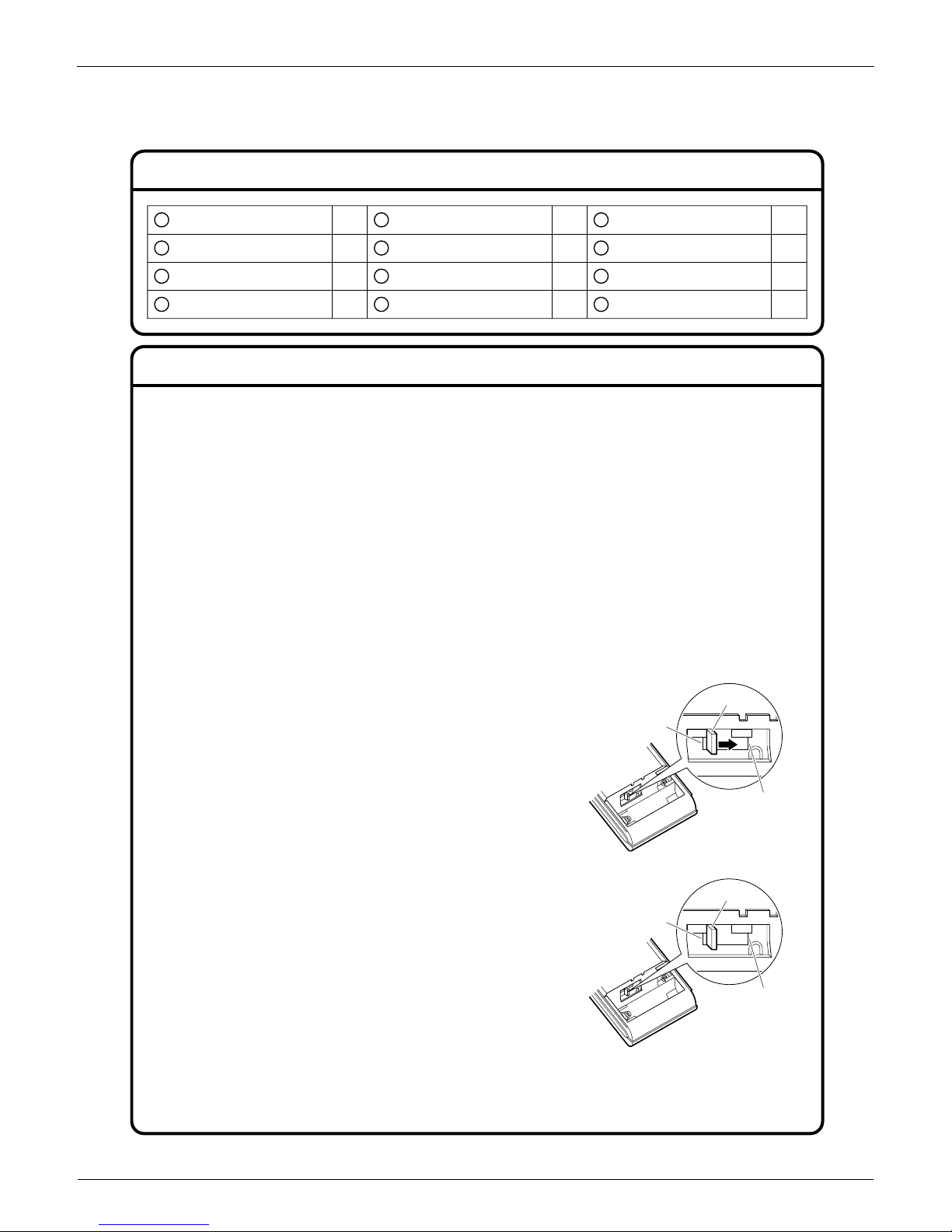
2. Wireless remote controller.
1) Turn on all the fluorescent lamps in the room, if any, and find the site where remote controller signals are
properly received by the indoor unit (within 23ft (7m)).
2) Make the DIP switch settings. Set according to the type of unit purchased by the customer. The default settings
are on the heat pump side.
• For cooling only (Outdoor unit model: RKS)
Set the DIP switch on the cooling only side.
•
For heat pump (Outdoor unit model: RXS)
Check that the DIP switch are on the heat pump side.
If they are set on the cooling only side, move them to the heat pump side.
• Before choosing the installation site, obtain user approval.
A
B
C
D
E
F
G
H
J
K
M
1
19
1
3
1
2
33
Mounting plate
Titanium Apatite Photocatalytic
Air-Purifying Filter
Wireless remote controller
Remote controller holder
Dry batteries AAA. LR03
(alkaline)
Fixing screws for remote controller
holder 1/8” × 13/16”L (M3 × 20L)
Operation manual
Screw cover
L
Installation manual
Mounting plate fixing screws
3/16” × 1”L (M4 × 25L)
Tube
1
Indoor unit fixing screws
3/16” × 1/2”L (M4 × 12L)
Accessories
Choosing an Installation Site
DIP switch
Heat pump
Cooling only
DIP switch
Heat pump
Cooling only
2
1
EDUS04-924A Installation Manual
Room Air Conditioners H-Series 27
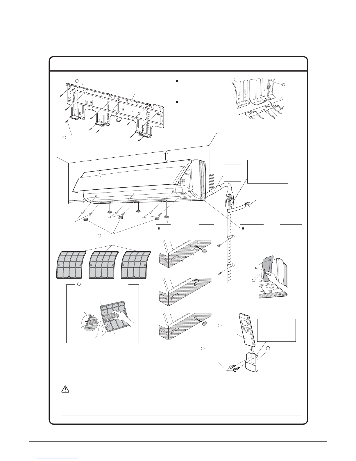
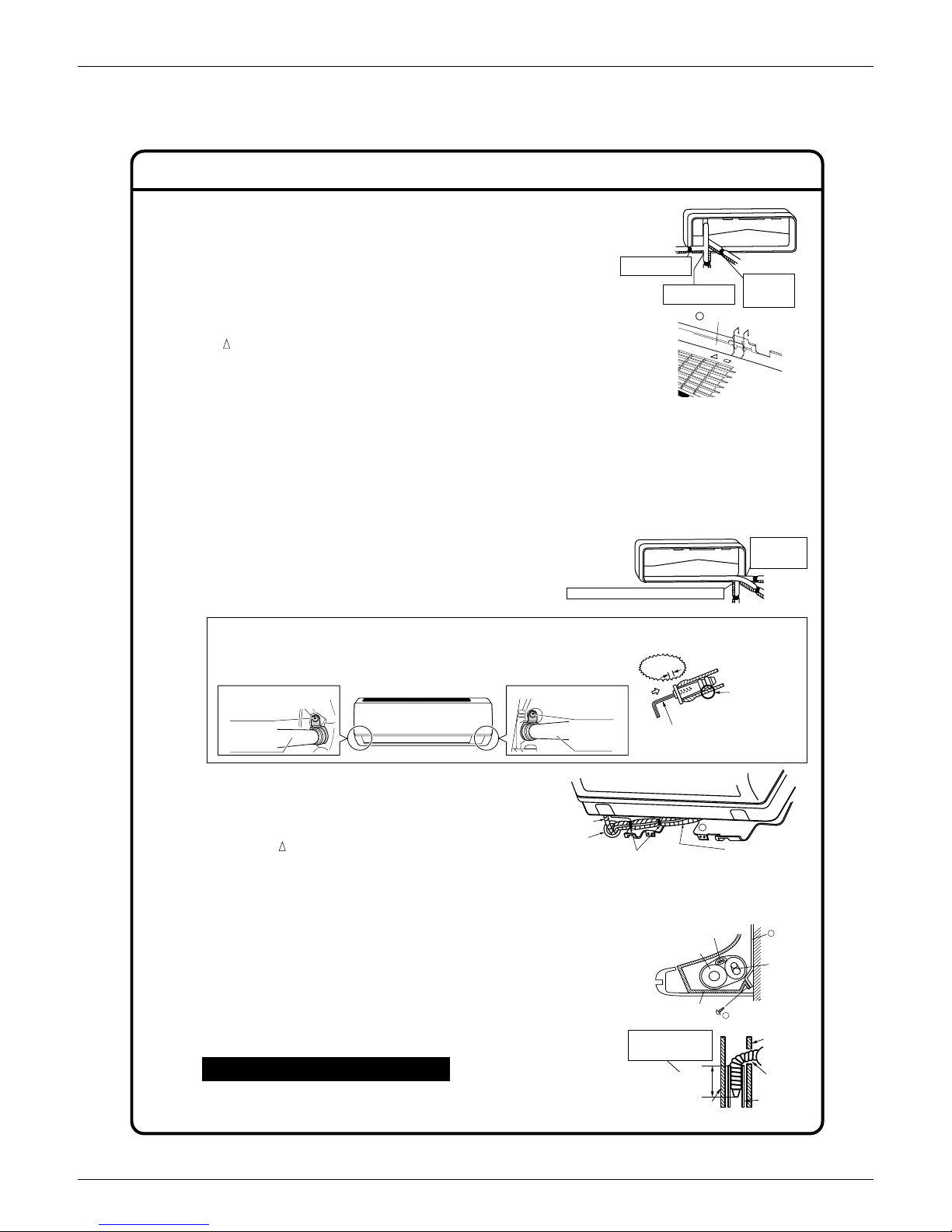
Indoor Unit Installation Drawings
Intelligent-eye Sensor
1) Do not hit or forcefully push the intelligent- eye sensor. . This can lead to damage and malfunction.
2) Do not place large objects near the sensor. Keep heating units or humidifiers outside the
sensor’s detection area.
CAUTION
1) Insert the tool into the groove of the
front grille fixture.
How to remove front grille fixture
2) Tur n the tool 90 in the direction of
the arrow.
3) Take out the front grille fixture.
1-3/16” (30mm) or more
from ceiling
Wrap the insulation pipe with
the finishing tape from bottom
to top.
Cut thermal insulation
pipe to an appropriate
length and wrap it with
tape, making sure that no
gap is left in the insulation
pipe’s cut line.
Caulk
pipe hole
gap
with putty.
C
Titanium Apatite Photocatalytic
Air-Purifying Filter (3)
How to attach the indoor unit.
Hook the claws of the bottom frame
to the mounting plate.
If the claws are difficult to hook,
remove the front grille.
How to remove the indoor unit.
Push up the marked area (at the
lower part of the front grille) to
release the claws. If it is difficult to
release, remove the front grille.
Opening service lid
Service lid is opening/closing type.
Opening method
1) Remove the service lid screws.
2) Pull out the service lid diagonally
down in the direction of the arrow.
3) Pull down.
Air filters
Front grille
A
Mounting
plate
Clip
Bottom frame
Mark (rear side)
A Mounting plate
Mounting plate fixing
screws 3/16” × 1”L (M4 × 25L) (9)
B
The mounting plate
should be installed on a
wall which can support the
weight of the indoor unit.
Intelligent-eye sensor
1-15/16” (50mm) or
more from walls
(on both sides)
Front panel
3/16” × 5/8”L
(M4 × 16L)
3/16” × 5/8”L
(M4 × 16L)
3/16” × 5/8”L
(M4 × 16L)
Service lidFront grille fixture
Wireless
remote
controller
D
E
Remote
controller holder
Before screwing the remote
controller holder to the wall,
make sure that control
signals are properly
received by indoor unit.
Fixing screws for
remote controller holder
1/8” × 13/16”L
(M3 × 20L) (2)
F
Titanium Apatite Photocatalytic
Air-Purifying Filter
Filter frame
Air filter
Ta b
Bottom of indoor unit
Front grille fixture
Screw cover
M
Installation Manual EDUS04-924A
28 Room Air Conditioners H-Series
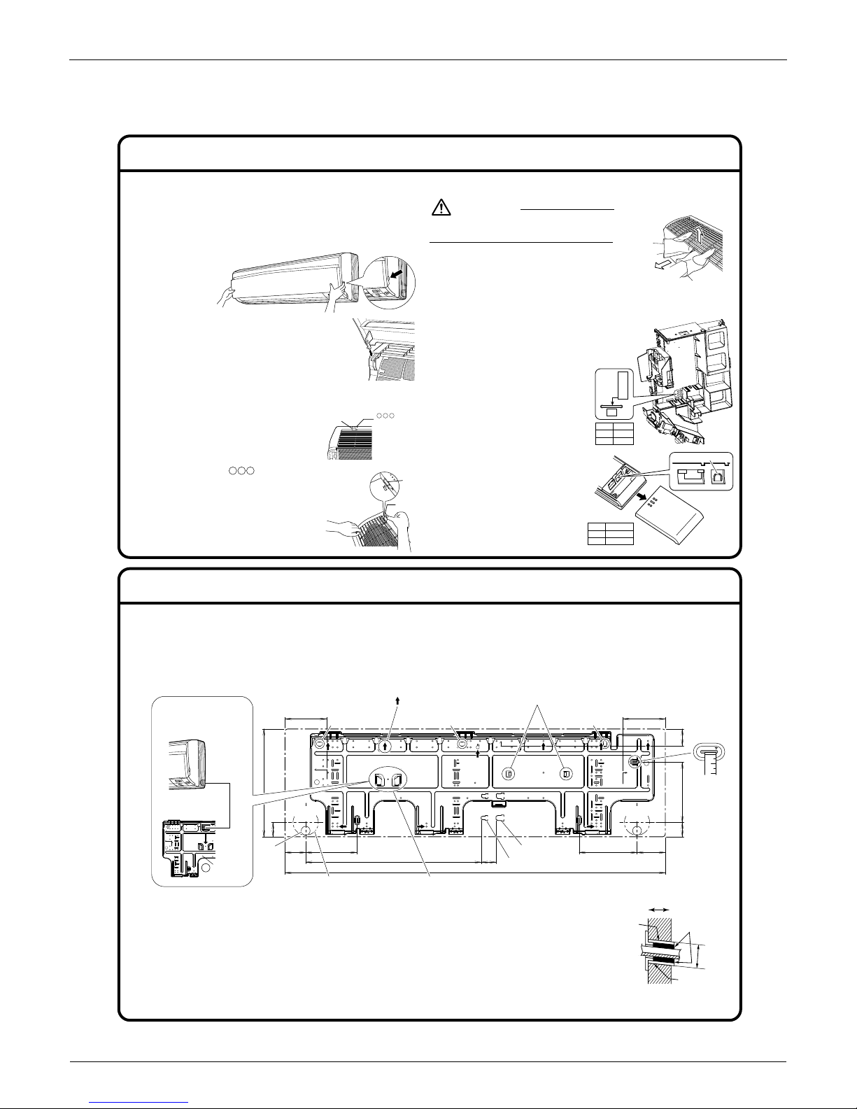
1. Installing the mounting plate.
• The mounting plate should be installed on a wall which can support the weight of the indoor unit.
1)
Temporarily secure the mounting plate to the wall, make sure that the panel is completely level, and mark the boring points on the wall.
2) Secure the mounting plate to the wall with screws.
Recommended mounting plate retention spots and dimensions
Indoor Unit Installation (1)
Installation Tips
1. Removing and installing front panel.
• Removal method
Hook fingers on the panel protrusions on the left and right
of the main body, and open until the panel stops. Slide the
front panel sideways to disengage the rotating shaft.
Then pull the front panel toward
you to remove it.
• Installation method
Align the tabs of the front panel with
the grooves, and push all the way in.
Then close slowly. Push the center of
the lower surface of the panel firmly to
engage the tabs.
2. Removing and installing the front grille.
• Removal method
1) Remove front panel to
remove the air filter.
2) Remove the front grille.
3) In front of the mark
of the front grille, there are
4 upper hooks. Lightly pull
the front grille toward you
with one hand, and push
down on the hooks with the
fingers of your other hand.
<When there is no work space because the unit is close to ceiling>
Be sure to wear protection gloves.
Place both hands under the center of the
front grille, and while pushing up, pull it
toward you.
• Installation method
1) Install the front grille and firmly engage the upper hooks
(4 locations).
2) Install 6 screws of the front grille.
3) Install the air filter and then mount the
front panel.
3. How to set the different
addresses.
When 2 indoor units are installed
in 1 room, the 2 wireless remote
controllers can be set for
different addresses.
1) In the same way as when
connecting to an HA system,
remove the metal plate
electrical wiring cover.
2) Cut the address jumper (JA)
on the printed circuit board.
3) Cut the address jumper (J4)
in the remote controller.
CAUTION
2. Boring a wall hole and installing wall embedded pipe.
•
For walls containing metal frame or metal board, be sure to use a wall embedded pipe
and wall cover in the feed-through hole to prevent possible heat, electrical shock, or fire.
•
Be sure to caulk the gaps around the pipes with caulking material to prevent water leakage.
1)
Bore a feed-through hole of 3-1/8 inch (80mm) in the wall so it has a down slope toward the outside.
2) Insert a wall pipe into the hole.
3) Insert a wall cover into wall pipe.
4)
After completing refrigerant piping, wiring, and drain piping, caulk pipe hole gap with putty.
φ3-1/8
(φ80)
7-1/2
(190)
2-1/16
(53)
5-1/4
(134)
5-3/16
(131)
1-3/4 (45)
1-3/4
(45)
13-3/8
(340)
2-9/16
(65)
φ3-1/8
(φ80)
6-5/16
(161)
7-3/16
(183)
3-1/2
(89)
47-1/4 (1200)
1-7/8
(47)
21-13/16 (554)
(length: inch (mm))
Use tape
measure
as shown.
Position
the end of
a tape
measure
at ∇.
Gas pipe end
Liquid pipe end
Keep here the piece cut out from the unit for pipingThrough-the-wall hole φ3-1/8 inch (φ80mm)
Drain
hose
position
Removed pipe
port cover
A
Mounting
plate
* The removed pipe por t
cover can be kept in the
mounting plate pocket.
Recommended mounting plate
retention spots (9 spots in all)
(Bolt size: 3/8” (M10))
(Bolt size: 3/8” (M10))
(Bolt size: 3/8” (M10))
Place a leveler on raised tab.
mark area
(4 locations)
Upper hook
Lightly pull the front grille
toward you with one
hand, and push down on
the hooks with the fingers
of your other hand.
(4 locations)
Push
down.
Upper hook
Upper hook
1) Push up.
2) Pull toward you.
Push the
rotating shaft
of the front
panel into the
groove.
ADDRESS
JA
ADDRESS
JA
EXIST
1
CUT 2
ADDRESS
J4
EXIST
CUT12
J4
Inside Outside
Caulking
Wall embedded
pipe
(Field supply)
Wall hole cover
(Field supply)
Wall embedded
pipe
(Field supply)
φ3-1/8”
(
φ
80mm)
EDUS04-924A Installation Manual
Room Air Conditioners H-Series 29
Indoor Unit Installation (2)
3-2. Left-side, left-back, or left-bottom piping.
1) Attach the drain hose to the underside of the refrigerant
pipes with adhesive vinyl tape.
2) Be sure to connect the drain hose to the drain port in
place of a drain plug.
3) Shape the refrigerant pipe along the pipe path marking
on the mounting plate.
4)
Pass drain hose and refrigerant pipes through the wall
hole, then set the indoor unit on mounting plate hooks,
using the markings at the top of indoor unit as a guide.
5) Pull in the inter-unit wire.
6) Connect the inter-unit pipes.
7) Wrap the refrigerant pipes and drain hose together with insulation tape
as right figure, in case of setting the drain hose through the back of the
indoor unit.
8) While exercising care so that the inter-unit wire do not catch indoor
unit, press the bottom edge of indoor unit with both hands until it is
firmly caught by the mounting plate hooks. Secure indoor unit to the
mounting plate with the screws (3/16” × 1/2”L (M4 × 12L)).
3. Installing indoor unit.
3-1. Right-side, right-back, or right-bottom piping.
1) Attach the drain hose to the underside of the refrigerant pipes
with an adhesive vinyl tape.
2)
Wrap the refrigerant pipes and drain hose together with an insulation tape.
3) Pass the drain hose and refrigerant pipes through the wall hole,
then set the indoor unit on the mounting plate hooks by using the
markings at the top of the indoor unit as a guide.
4)
Open the front panel, then open the service lid. (Refer to Installation Tips.)
5) Pass the inter-unit wire from the outdoor unit through the feed-
through wall hole and then through the back of the indoor unit.
Pull them through the front side. Bend the ends of tie wires
upward for easier work in advance. (If the inter-unit wire ends are
to be stripped first, bundle wire ends with adhesive tape.)
6) Press the bottom frame of the indoor unit with both hands to set it
on the mounting plate hooks. Make sure that the wires do not
catch on the edge of the indoor unit.
3-3. Wall embedded piping.
Follow the instructions given under
1) Insert the drain hose to this depth so it won’t be pulled out of
the drain pipe.
Left-side, left-back, or left-bottom piping .
Remove pipe port cover here for left-bottom piping.
Remove pipe port
cover here for
left-side piping.
Left-bottom piping
Left-side
piping
Left-back
piping
How to set the drain hose.
• Insert drain hose and tighten indoor unit fixing screw.
(Forgetting to attach this may cause water leakages.)
* The drain hose is on the back of the unit.
How to set the drain plug.
Front side of unit
Drain hose attachment position
Attachment on the left side
Drain hose
Indoor unit
fixing screw
Attachment on the right side (factory default)
Drain hose
Insulation
fixing screw
No gap
Do not apply
lubricating oil
(refrigerant oil)
when inserting.
Application of
causes deterioration
and drain leakage
of the plug.
Insert a hexagon wrench
(3/16 inch (4mm))
Wrap insulation tape
around the bent portion
of refrigerant pipe.
Overlap at least half the
width of the insulation
tape with each turn.
Drain
hose
Caulk this hole
with putty or
caulking material.
Bind with plastic
tape.
A
Mounting plate
Refrigerant
pipes
Drain hose
Bottom frame
H 3/16” × 1/2”L
(M4 × 12L) (3 point)
Inter-unit wire
Mounting
plate
A
Inner wall
Vinyl chloride
drain pipe
(VP-30)
Drain hose
1-15/16”
(50mm)
or more
Insert drain hose to this
depth so it won’t be
pulled out of drain pipe.
Outer wall
Right-bottom
piping
Right-back piping
Bind coolant pipe
and drain hose
together with
insulation tape.
Remove pipe port cover
here for right-side piping.
Remove pipe port cover
here for right-bottom piping.
Mounting plate
A
 Loading...