

Page 1

Air Handling Unit
D-EOMAH00006-20EN
Operation Manual
1
Operating Manual
Air Handling Unit
Application Software name: Airstream
D-EOMAH00006-20EN
Page 2

Operation Manual
Air Handling Unit
Operation Manual
2
Air Handling Unit
D-EOMAH00006-20EN
Table of Contents
1. Revision History..................................................................................................................... 4
2. Air Handling Unit Safety Information...................................................................................... 5
3. Introduction .......................................................................................................................... 6
4. User interface........................................................................................................................ 8
4.1 Controller POL687/638 Interfaces ...................................................................................................................... 8
4.2 External Human Machine Interfaces .................................................................................................................. 9
4.2.1 6-Button LCD HMI (POL871) ................................................................................................................................................ 9
4.2.2 Push & Roll key HMI (POL895) ............................................................................................................................................. 9
4.3 WEB-Human Machine Interface ....................................................................................................................... 11
4.4 Communication Modules .................................................................................................................................. 15
4.4.1 Modbus module installation .............................................................................................................................................. 16
4.4.2 BACnet IP module installation ........................................................................................................................................... 16
4.5 Basic Control System Diagnostic ....................................................................................................................... 16
5. Control Functions ................................................................................................................ 19
5.1 Air Quality Control Function ............................................................................................................................. 20
5.2 Humidity Control Function ................................................................................................................................ 20
5.3 Summer/Winter mode changeover functions .................................................................................................. 21
6. Main Menu screen .............................................................................................................. 22
7. Control Source .................................................................................................................... 24
8. Actual Mode........................................................................................................................ 25
9. Unit State ............................................................................................................................ 26
10. Active Setpoint .................................................................................................................... 28
11. Local Switch ........................................................................................................................ 29
12. Summer/Winter state .......................................................................................................... 30
13. Setpoints ............................................................................................................................. 32
14. I/O Overview ....................................................................................................................... 35
15. Time Scheduler.................................................................................................................... 36
15.1 Day Scheduler.................................................................................................................................................... 37
15.2 Calendar exception and Calendar fix off........................................................................................................... 38
16. Status/Settings .................................................................................................................... 40
16.1 Temperature Control ........................................................................................................................................ 41
16.2 Air Quality Control............................................................................................................................................. 42
16.3 Humidity Control ............................................................................................................................................... 43
16.4 Fans Control ...................................................................................................................................................... 44
16.4.1 Fast Heating/Cooling .......................................................................................................................................................... 48
16.5 Dampers Control ............................................................................................................................................... 49
16.6 Heat Recovery Control ...................................................................................................................................... 50
16.7 Cooling Coil Control........................................................................................................................................... 50
16.8 Heating Coil Control .......................................................................................................................................... 51
16.9 Pumps Control ................................................................................................................................................... 53
Page 3

Air Handling Unit
Operation Manual
Air Handling Unit
D-EOMAH00006-20EN
Operation Manual
3
16.10 ERQ Control ....................................................................................................................................................... 53
16.10.1 ERQ Status ........................................................................................................................................................................... 53
16.10.2 ERQ Settings ........................................................................................................................................................................ 54
16.11 Post-Heating Control ......................................................................................................................................... 56
16.12 Pre-Heating Electrical Control ........................................................................................................................... 57
16.13 Pre-Heating Water Control ............................................................................................................................... 58
17. Alarm handling .................................................................................................................... 60
17.1 Alarm restore .................................................................................................................................................... 60
17.2 Alarm list............................................................................................................................................................ 61
18. About Unit .......................................................................................................................... 71
Appendix A: Room Unit Module - POL822 ................................................................................. 73
Buttons Overview .......................................................................................................................................73
Display Overview ........................................................................................................................................74
AHU On-Off (1) ...........................................................................................................................................75
Occupancy On-Off (2) ..................................................................................................................................75
Date and time (3) ........................................................................................................................................76
Temperature Setpoint Offset (4 & 5) .............................................................................................................76
Fan Speed Display (7) ..................................................................................................................................76
Summer/Winter changeover (8) ...................................................................................................................76
Mounting instructions .................................................................................................................................77
Appendix B: iTM Installation & Configuration ............................................................................ 78
Page 4

Operation Manual
Air Handling Unit
Operation Manual
4
Air Handling Unit
D-EOMAH00006-20EN
1. Revision History
Name
Revision
Date
Scope
D-ECCAH00006-20EN
2
June 2020
The following sections have been upgraded with
the software modifications introduced by software
Airstream 3.15.A.:
• 16.12 Pre-Heating Electrical Control
D-EOMAH00006-20EN
1
January
2020
Scope of this document is to update the Operation
instructions for Units with application software
3.10.A and later.
Old versions
For Units with application software 2.90.A and
earlier.
Page 5

Air Handling Unit
Operation Manual
Air Handling Unit
D-EOMAH00006-20EN
Operation Manual
5
2. Air Handling Unit Safety Information
Observe all safety directions and comply with the corresponding general safety regulations in order to
prevent personal injury and damage to property.
• Safety devices may not be removed, bypassed or taken out of operation.
• Apparatus and system components may only be used in a technically fault-free state. Faults that can
affect safety must be rectified immediately.
• Observe the required safety instructions against excessively high contact voltages.
• The plant may not be in operation if the standard safety devices are out of operation or if their effects
are influenced in some other way.
• All handling that affects the prescribed disconnection of the protective extra-low voltage (AC 24 V)
must be avoided.
• Disconnect the supply voltage before opening the apparatus cabinet. Never work when the power
is on!
• Avoid electromagnetic and other interference voltages in signal and connection cables.
• Assembly and installation of system and plant components may only be performed in accordance
with corresponding installation instructions and instructions for use.
• Every electric part of the system must be protected against static charging: electronic components,
open printed circuit boards, freely accessible connectors and apparatus components that are
connected with the internal connection.
• All equipment that is connected to the system must be CE marked and comply with the Machine
Safety Directive.
Page 6
Operation Manual
Air Handling Unit
Operation Manual
6
Air Handling Unit
D-EOMAH00006-20EN
3. Introduction
This operating manual provides the basic information that allows the control of the Daikin Air Handling Unit
(AHU).
AHUs are used for air conditioning and air handling in terms of temperature, humidity and CO2 level control.
There are four types of AHU, based on the external devices used to produce cooling or heating:
1. AH-ERQ-U
The AH-(ERQ)-U is connected with the Daikin ERQ condensing unit;
2. AH-W-U
The AH-(Water)-U is connected with an external device that provides hot water or cold water used
in a water heat exchanger;
3. AH-DX-U
The AH-(Direct eXpansion)-U is connected with an external condenserless unit;
4. AH-WDX-U
This type of AH-(Water Direct eXpansion)-U can be connected to both water and direct expansion
devices.
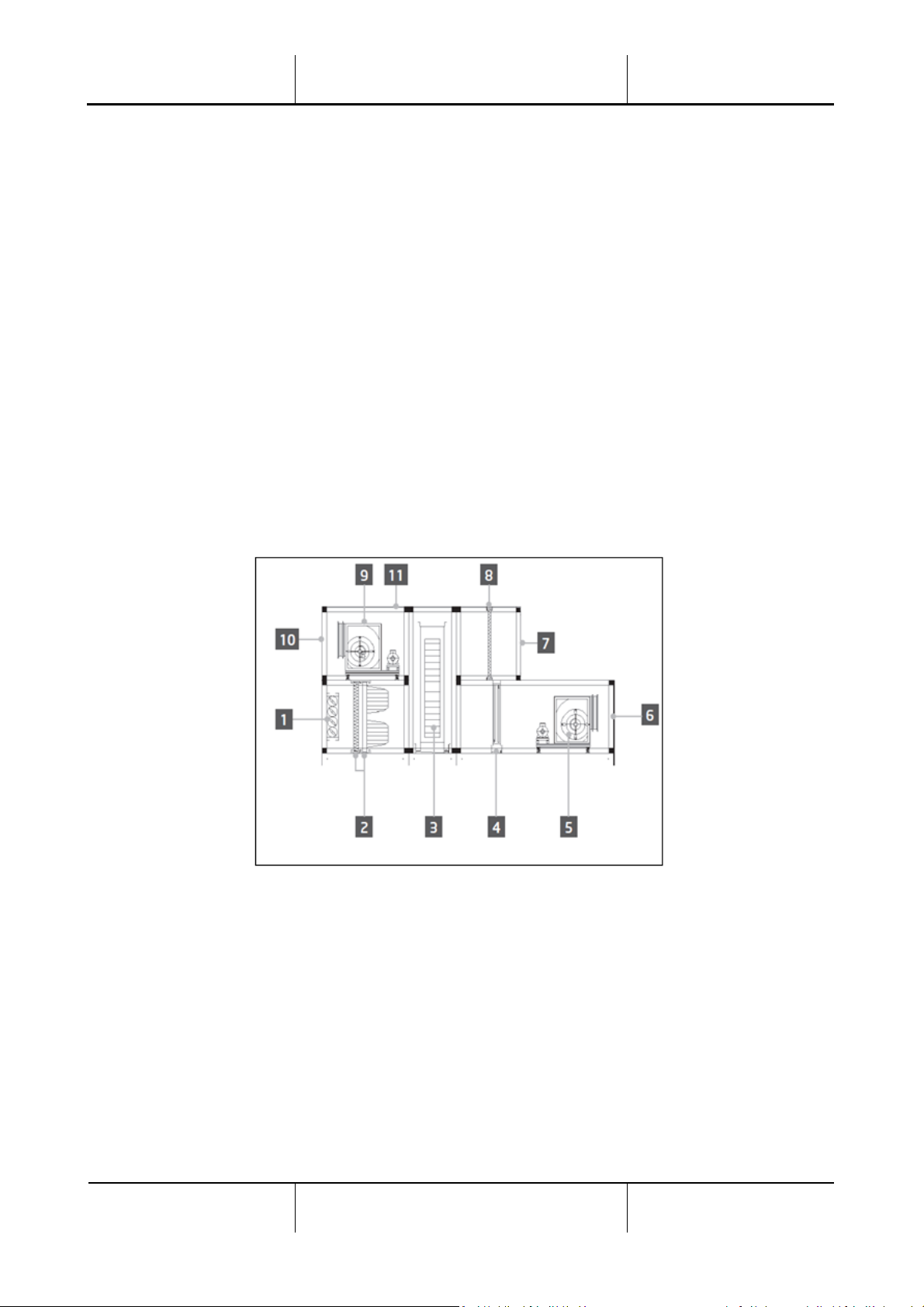
The diagrams in Figures 1 and 2 show two possible AHU layouts:
Figure 1: AHU example layout #1
1. Fresh air inlet / damper
2. Bag filter
3. Heat wheel
4. Dx coil
5. Supply fan
6. Supply air outlet
7. Return air inlet
8. Filter
9. Return fan
10. Exhaust air outlet
11. Roof for outdoor installation
Page 7
Air Handling Unit
Operation Manual
Air Handling Unit
D-EOMAH00006-20EN
Operation Manual
7
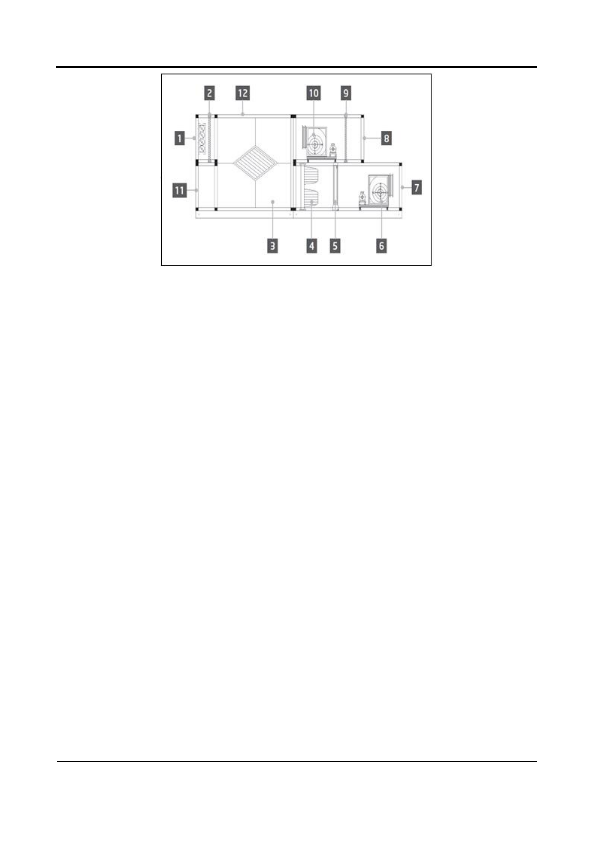
Figure 2: AHU example layout #2
1. Fresh air inlet / damper
2. Panel-filter
3. Heat recovery plate exchanger
4. Bag filter
5. Dx coil
6. Supply fan
7. Supply air outlet
8. Return air inlet
9. Panel filter
10. Return fan
11. Return air outlet
12. Roof for outdoor installation
The main components of a Daikin AHU are:
- Air filters: pre-filter, fine filter, bag filter, HEPA filter.
Every AHU unit can be equipped with several types of filters used to clean the air from little particles
of dust, pollen etc.
- Device for heat/cool recovery: Wheel, Cube Plate Exchanger, RAR coil or Mixing Damper.
These devices are used to recover cooling or heating from the return air. Part of the exhaust air is
mixed with fresh air so that the inlet air temperature is closer to the desired one.
- Water/Electrical/Dx coils.
These are the devices used for air temperature conditioning.
- Supply and return Fan.
These devices are used to regulate the air volume, and often they are controlled via an inverter.
- Supply and return air dampers.
These devices allow the air flow through the AHU when being activated.
Page 8
Operation Manual
Air Handling Unit
Operation Manual
8
Air Handling Unit
D-EOMAH00006-20EN
4. User interface
In this chapter are explained the different operative modes available to the user for AHU control.
4.1 Controller POL687/638 Interfaces
Two different controllers are available for AHU control, depending on the chosen model: POL687 for AHUModular (or Compact for software version previous to Airstream 0.10.B), POL638 for AHU-Professional.
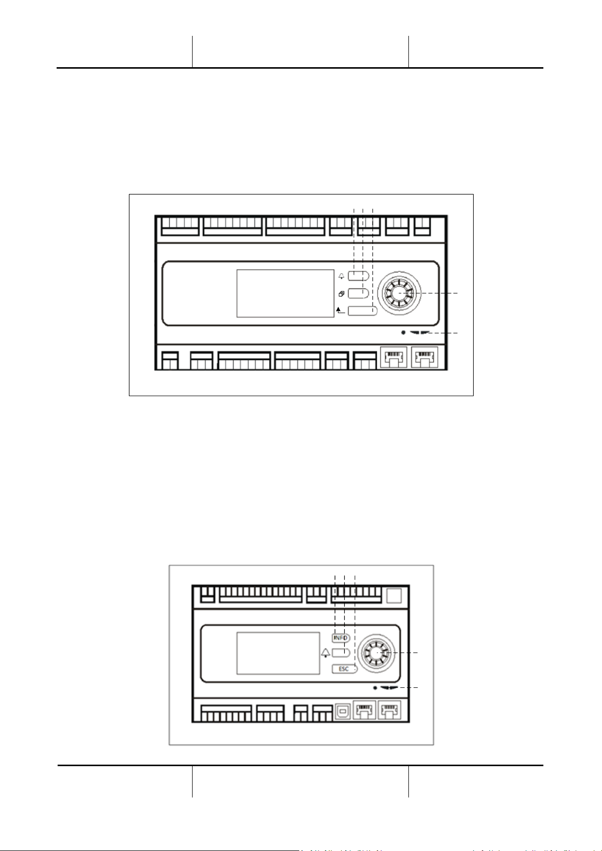
Next figure shows POL687 controller interface schematic.
1 2
3
4
5
Controller POL687
With reference to figure above, it is possible to identify:
1) Alarm button: this button allows the user to directly access the Alarms menu.
2) Main Menu button: this button is used to return to the Main Menu screen at all times.
3) Return button: this button allows the user to go back to the previous screen.
4) Wheel select button: this button allows the user to surf through the menus; pressing the button will
enter to the next page, turning it allows the user to scroll up or down through the current page.
5) BSP/BUS LED: these LEDs allow the user to monitor POL687 controller status.
Next figure shows POL638 controller interface.
4
5
2 1 3
Page 9

Air Handling Unit
Operation Manual
Air Handling Unit
D-EOMAH00006-20EN
Operation Manual
9
Controller POL638
The differences between POL687 and POL638 interfaces are the “Main Menu” and “Return” buttons, which
are mapped respectively to “INFO” and “ESC” buttons.
4.2 External Human Machine Interfaces
The Human Machine Interfaces (HMI) are devices that can be connected to the main controller (POL687/638)
in order to create a remote interface between the controller and the user.
Two different remote interfaces are available: POL871 and POL895. Both will replicate exactly the same page
that is seen on the principal controller and must be connected to the “T-HI” output of the controller.
4.2.1 6-Button LCD HMI (POL871)
The following figure shows the POL871, a 6-buttons LCD interface, and how to connect to it to the main
controller through a simple Ethernet cable:
With reference to the above, it is possible to identify the following buttons:
1. Button 1: Main menu.
This button has an internal LED that indicates the status of the AHU:
- LED green: AHU running
- LED blinking orange: AHU Alarm
2. Button 2: Use this button to go directly to the alarms page.
3. Button 3: Back button.
4. Button 4: Scroll up button / increase values.
5. Button 5: Scroll down button / decrease value.
6. Button 6: Enter / validate button.
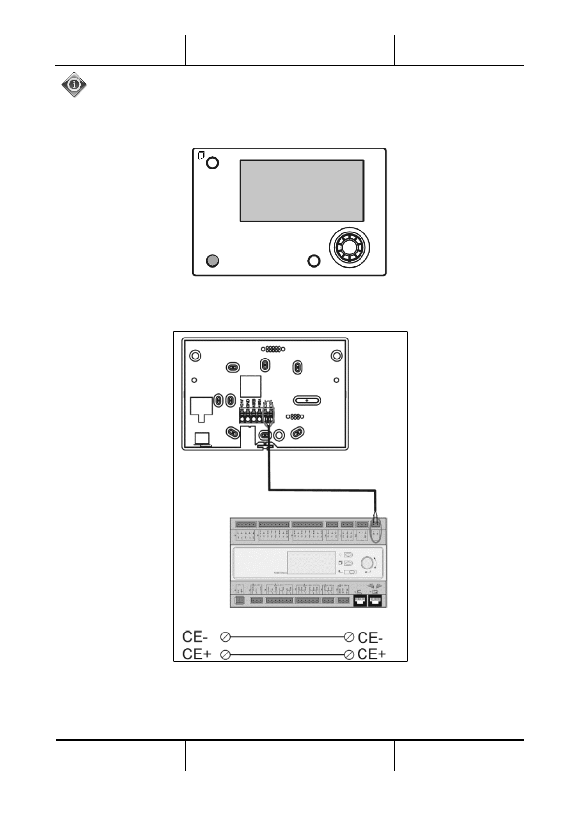
4.2.2 Push & Roll key HMI (POL895)
The POL895 is an external interfaces with a push & roll key which replicates the integrated controller HMI
navigation (if provided). All views, data and setpoint adjustments available on main controller HMIs are
available on the remote panel. Navigation is identical to the main controller as described in this manual.
The initial screen when the remote is turned on shows the units connected to it. Highlight the desired unit
and press the wheel to access it.
Page 10
Operation Manual
Air Handling Unit
Operation Manual
10
Air Handling Unit
D-EOMAH00006-20EN
Long press of the ESC button will show the list of the connected controllers. Use the wheel to select the
desired controller.
The Remote HMI can be extended up to 700m using the Process Bus connection (PB) available on the main
controller.
With a daisy-chain connection as below, a single HMI can be connected up to 8 units. Refer to the specific
HMI manual for additional details.
Page 11
Air Handling Unit
Operation Manual
Air Handling Unit
D-EOMAH00006-20EN
Operation Manual
11
The Remote interface can be also connected with an Ethernet cable (twisted pair). Maximum length changes
depending on cable characteristic:
• Shielded cable: max length 50m,
• Non-shielded cable: max length 3m.
Connection in this case has to be executed as shown in the following image.
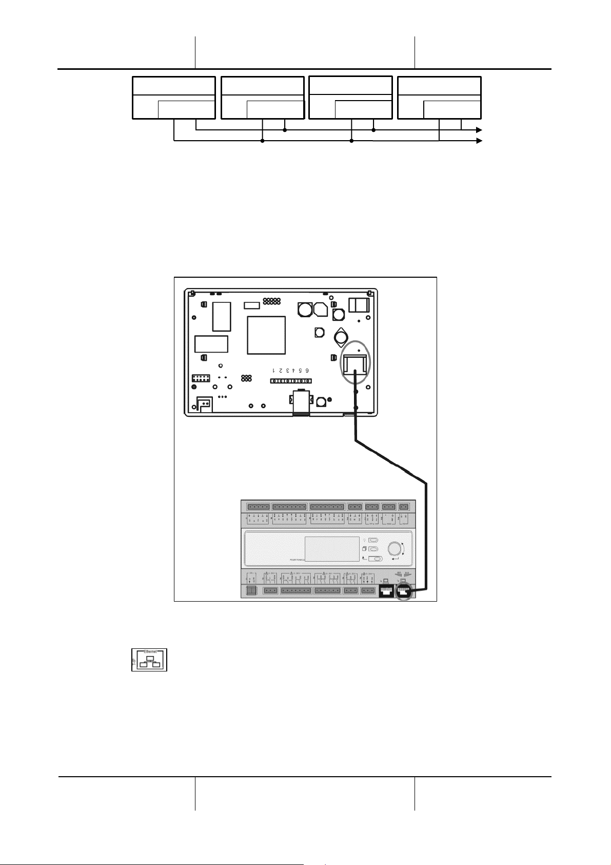
4.3 WEB-Human Machine Interface
The main controller can be connected to a PC using an Ethernet cable on the “Ethernet” output of the
controller itself .
CE- CE+
Remote HMI
CE- CE+
Unit 1
CE- CE+
Unit 2
CE- CE+
Unit 3
Page 12
Operation Manual
Air Handling Unit
Operation Manual
12
Air Handling Unit
D-EOMAH00006-20EN
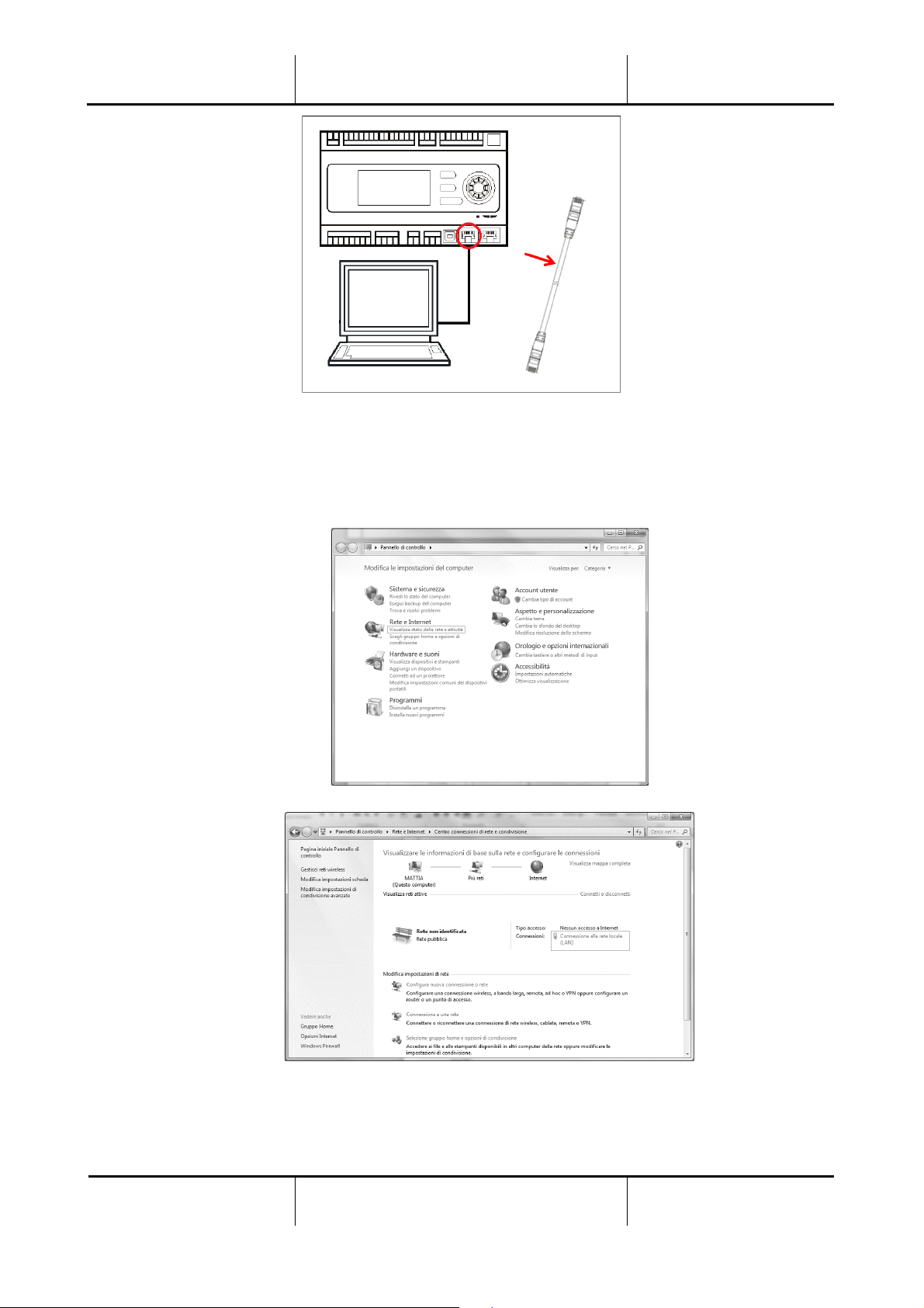
To access to the controller menu through the WEB-HMI it is necessary to follow the following steps:
1. Set a static IP (Windows 7):
Start -> Control Panel -> View network status and tasks -> Local Area Connection
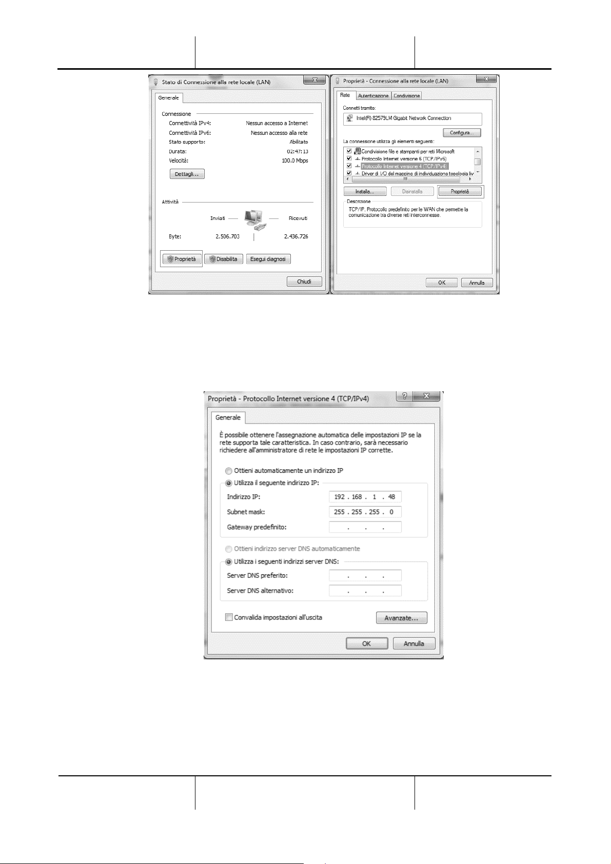
Properties -> Internet Protocol 4(TCP/IPv4) -> Properties
Page 13
Air Handling Unit
Operation Manual
Air Handling Unit
D-EOMAH00006-20EN
Operation Manual
13
2. Set “Use the following IP address” and “Use the following DNS server addresses” and manually insert:
- IP address = 192.168.1.xxx, where xxx indicates any number between 1 and 254, except 42
- Subnet mask = 255.255.255.0
3. Press Ok
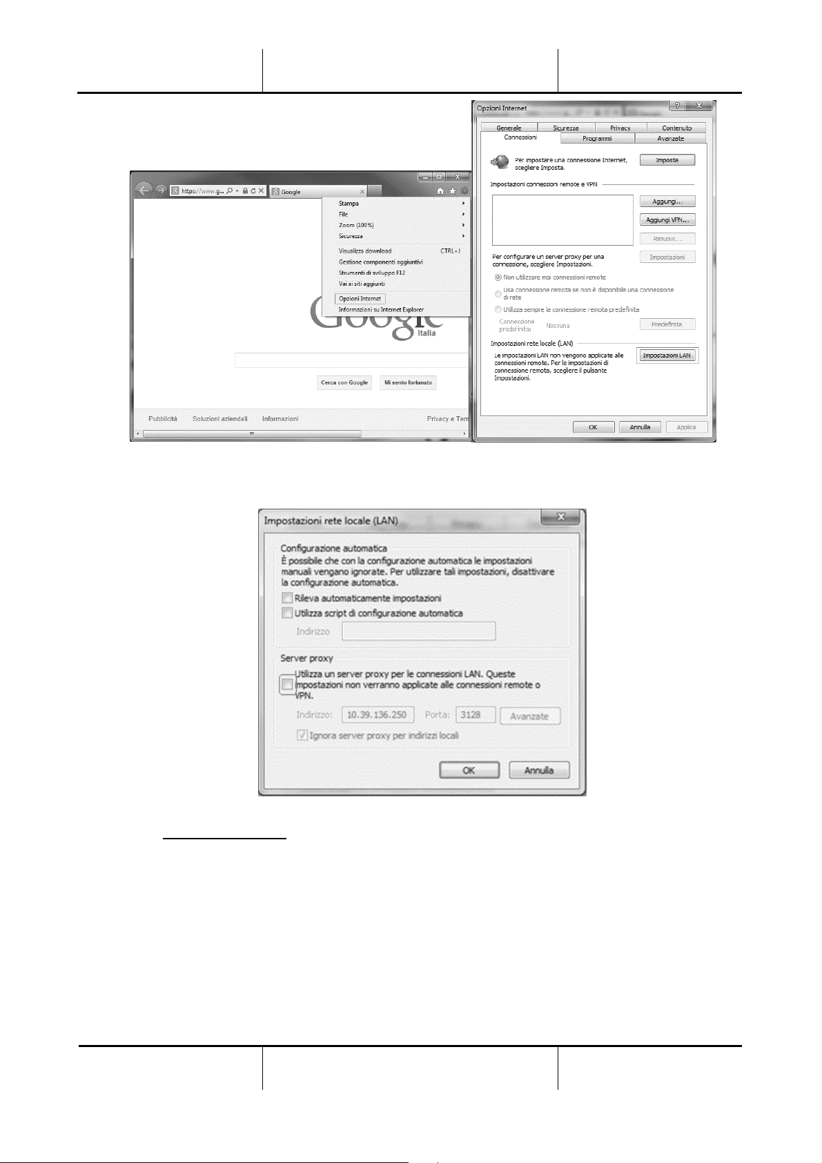
Before launching the WEB-HMI, the user must check if any proxy servers are disabled on the internet
browser:
1. For Internet Explorer select:
Tools -> Internet Options -> Connections -> Lan settings
Page 14
Operation Manual
Air Handling Unit
Operation Manual
14
Air Handling Unit
D-EOMAH00006-20EN
2. Disable “Use a proxy server for your LAN (These settings will not apply to dial-up or VPN
connections)”
3. Type http://192.168.1.42 in the internet browser bar and, when asked, insert the following user
name and password:
- User name: ADMIN
- Password: SBTAdmin!
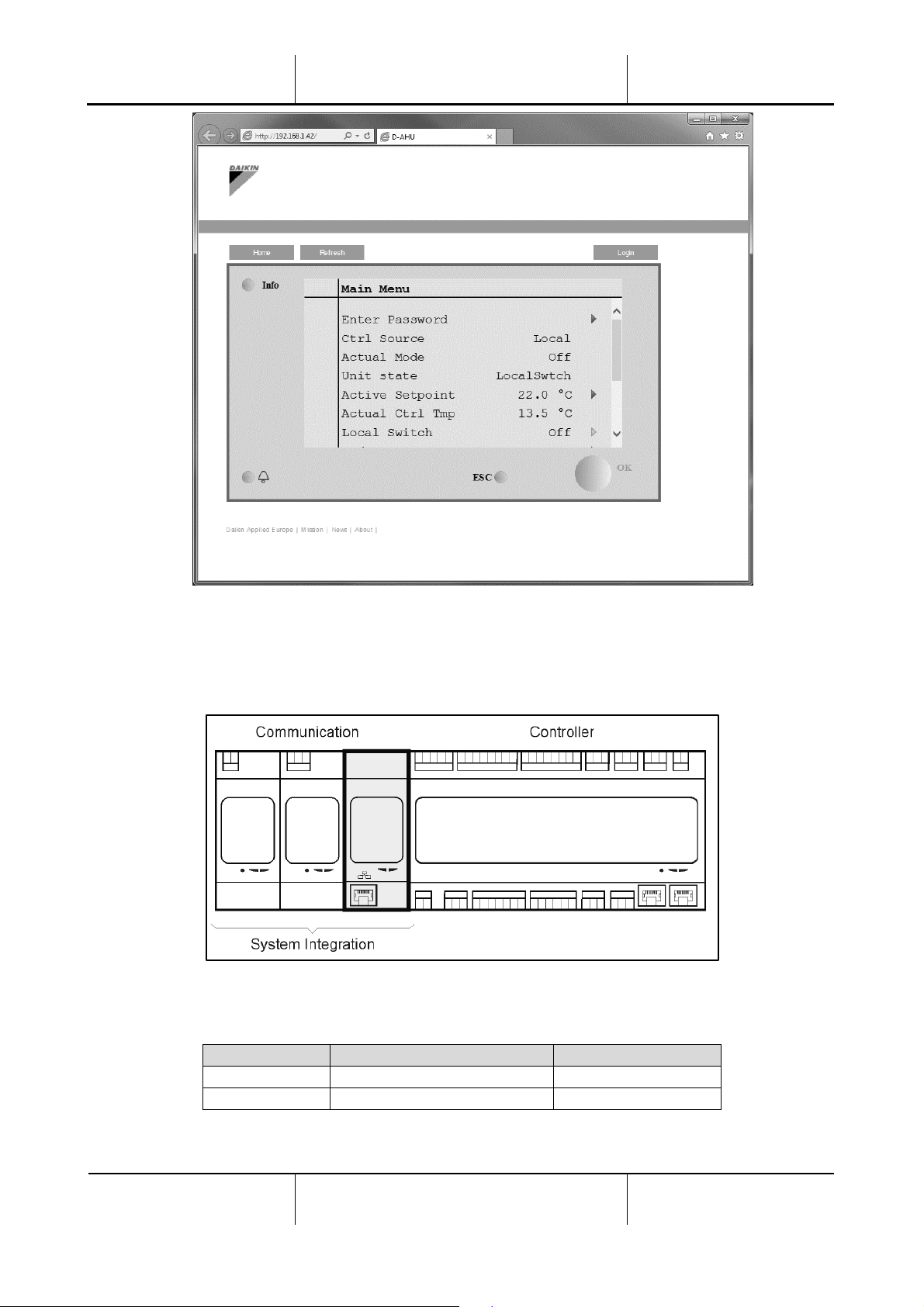
The following page should appear.
Page 15
Air Handling Unit
Operation Manual
Air Handling Unit
D-EOMAH00006-20EN
Operation Manual
15
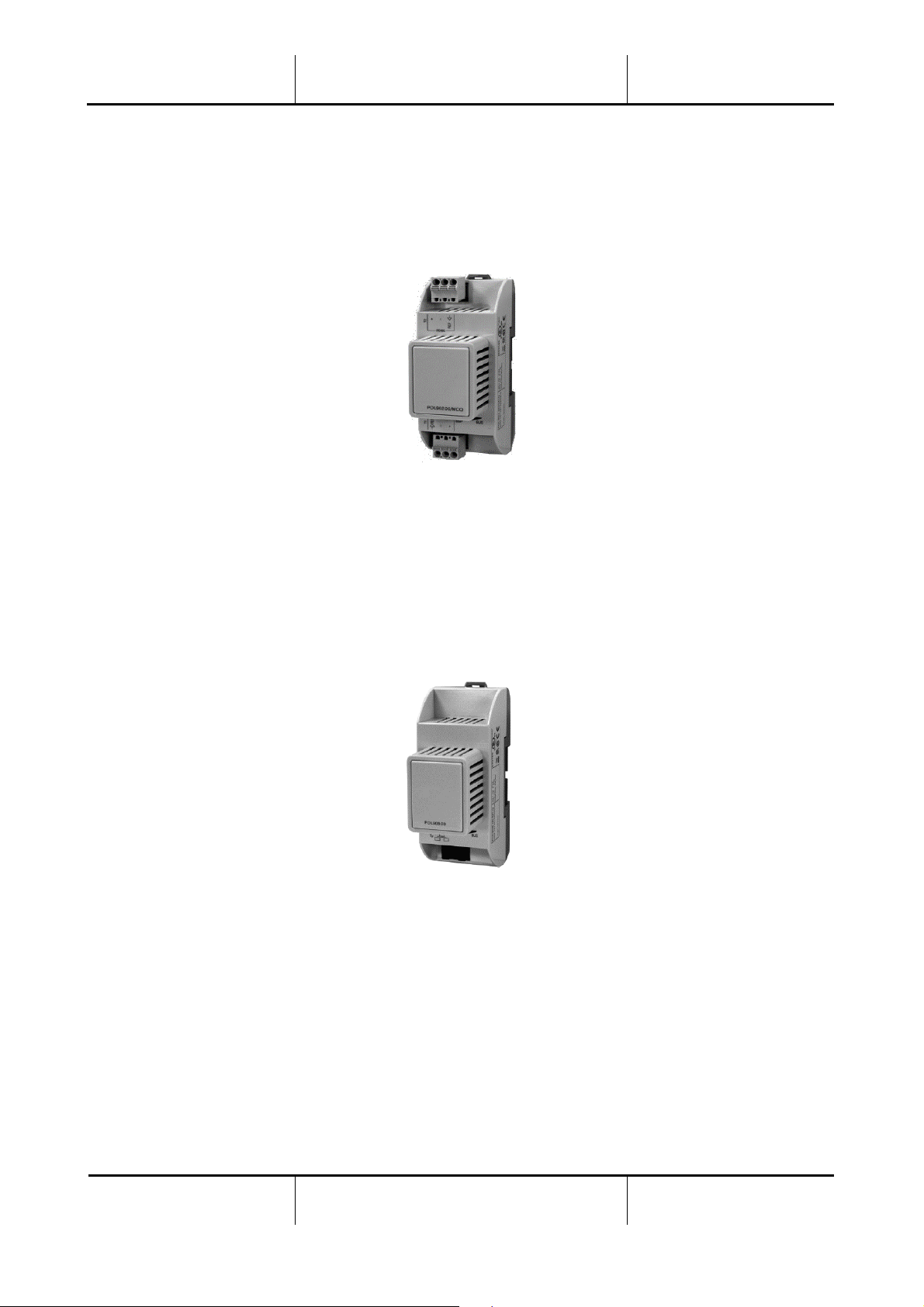
4.4 Communication Modules
Any of the modules described in this section can be connected directly to the left side of the main controller
to allow a BAS or other remote interface to function. To make the connection is required to remove the
knockout covers on both unit controller and communication module, so the installation will results as follows:
The controller should automatically detect new modules after booting up. The configuration strictly depends
on the communication protocol used.
Module
Part Number
Usage
Modbus
POL902.00/MCQ
Optional
BACnet/IP
POL908.00/MCQ
Optional
Page 16
Operation Manual
Air Handling Unit
Operation Manual
16
Air Handling Unit
D-EOMAH00006-20EN
Separate documents contains all the information about the different protocols supported and a full list of
available variables.
4.4.1 Modbus module installation
In case of Modbus connection with a BMS, the corresponding module has to be installed on the unit (POL902).
It has to be connected to the Unit Controller as indicated in the previous section.
The module has two different ports available but only the top port is programmed and operational. A
dedicated menu allows to properly setup the communication parameters.
4.4.2 BACnet IP module installation
In case of BACnet connection with a BMS, the corresponding module has to be installed on the unit (POL908).
It has to be connected to the Unit Controller as indicated in the previous section.
A dedicated menu allows to properly setup the communication parameters.
4.5 Basic Control System Diagnostic
Unit controller, extension modules and communication modules are equipped with two status LED, BSP and
BUS, to indicate the operational status of the devices (see section 3.1 for their location). The “BUS” LED
indicates the status of the communication with the controller. The meaning of the two status LED is indicated
below.
Page 17
Air Handling Unit
Operation Manual
Air Handling Unit
D-EOMAH00006-20EN
Operation Manual
17
- MAIN CONTROLLER
- BSP LED
LED Color
Mode
Solid Green
Application running
Solid Yellow
Application loaded but not running (*) or BSP Upgrade mode active
Solid Red
Hardware Error (*)
Flashing Green
BSP startup phase. The controller needs time for starting.
Flashing Yellow
Application not loaded (*)
Flashing Yellow/Red
Fail safe mode (in case that the BSP upgrade was interrupted)
Flashing Red
BSP Error (software error*)
Flashing Red/Green
Application/BSP update or initialization
(*) Contact Service.
- EXTENSION MODULES
- BSP LED
LED Color
Mode
Solid Green
BSP running
Solid Red
Hardware Error (*)
Flashing Red
BSP Error (*)
Flashing Red/Green
BSP upgrade mode
- BUS LED
LED Color
Mode
Solid Green
Communication running, I/O working
Solid Yellow
Communication running but parameter from the application wrong
or missing, or uncorrect factory calibration
Solid Red
Communication down (*)
- COMMUNICATION MODULES
- BSP LED (same for all modules)
LED Color
Mode
Solid Green
BPS running, communication with controller
Solid Yellow
BSP running, no communication with controller (*)
Solid Red
Hardware Error (*)
Flashing Red
BSP Error (*)
Flashing Red/Green
Application/BSP update
(*) Contact Service.
- BUS LED (BACnet IP)
LED Color
Mode
Solid Green
Ready for Communication. The BACnet Server is started. It doesn't
indicate an active communication
Solid Yellow
Startup. The LED stays yellow until the module receives an IP
Address, therefore a link must be established.
Solid Red
BACnet Server down. Automatic restart after 3 seconds is initiated.
Page 18

Operation Manual
Air Handling Unit
Operation Manual
18
Air Handling Unit
D-EOMAH00006-20EN
- BUS LED (Modbus)
LED Color
Mode
Solid Green
All Communication running
Solid Yellow
Startup, or one configured channel not communicating to the
Master
Solid Red
All configured Communications down (no communication to the
Master). The timeout can be configured. In case that the timeout is
zero, the timeout is disabled.
Page 19
Air Handling Unit
Operation Manual
Air Handling Unit
D-EOMAH00006-20EN
Operation Manual
19
5. Control Functions
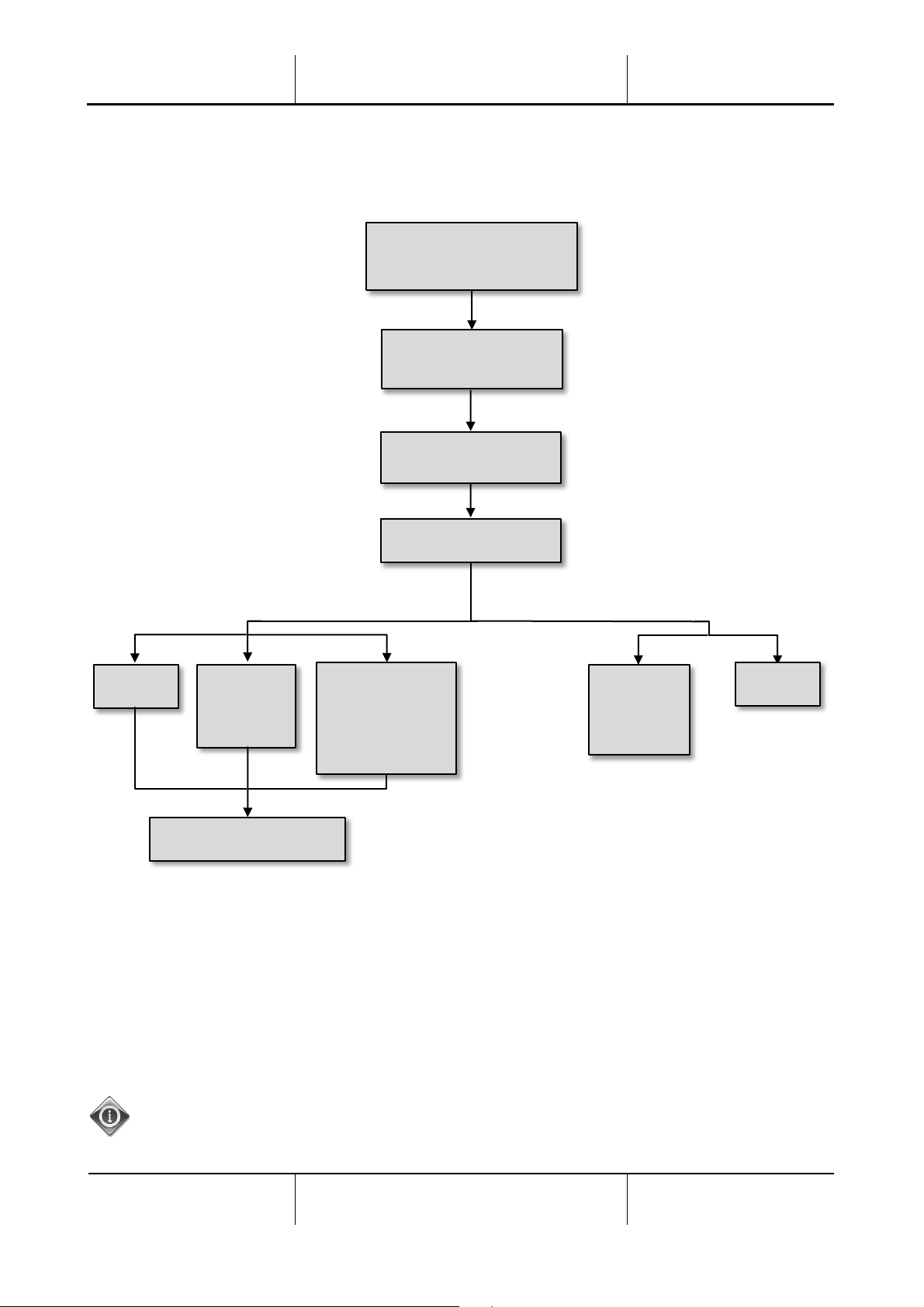
This section describes the main control functions available in Daikin Air Handling Units. A typical activation
sequence of the devices installed in Daikin AHU for thermoregulation control is showed below.
The starting sequence is performed according to an energy saving management logic, in order to satisfy the
desired temperature setpoint.
As soon as a device is fully operational (i.e. operates at 100%), the next device starts according to the
sequence shown in the figure above. The same sequence describes also the devices turn-off order by
following the opposite direction, ensuring that the upper devices are directly controlled only when the lowest
ones are not working. This ensure that the temperature setpoint is always satisfied with the lowest energy
consumption.
The activation sequence strictly depends on the devices actually installed in your AHU, so it may changes
accordingly.
Mixing Damper
Supply/Return
Fan Start
Fresh/Exhaust
Air Damper Opening
Heat Recovery Device
ERQ
+
Heating Water
Coil
ERQ
Heating
Water Coil
Electric Coil
Cooling
Water Coil
ERQ
Heating
Cooling
Page 20

Operation Manual
Air Handling Unit
Operation Manual
20
Air Handling Unit
D-EOMAH00006-20EN
5.1 Air Quality Control Function
The Air Quality control function provides the AHU with the capability of monitoring and control the actual
level of CO2 concentration in the environment by modulating the devices that control the air flow (fans and
dampers) in order to facilitate the air exchange between inside and outside, while ensuring in the meantime
the respect of the temperature setpoint selected.
In particular, when the CO2 level (in ppm) is higher than the desired setpoint, the actual fan setpoint is
increased proportionally in order to increment clean air volume coming from the outside (Supply air duct)
and at the same time extract more rapidly the environment exhaust air (Return air duct). During this state,
the dampers (both mixing and external) are modulated in order to increase fresh air flow.
For additional information on air quality control logic and parameters configuration refer to Air Quality
Control section (15.2).
The Air Quality control function is available only if the AHU is provided with a CO2 sensor.
5.2 Humidity Control Function
The AHU software is provided with both humidification and dehumidification functions in order to control
the environment relative humidity and satisfy the desired humidity setpoint. These functions may be both
available or not, depending on the configuration of the AHU.
- Humidification Control
During AHU winter mode, the controller monitors the humidity sensor readings and activates the
control of the humidifier as soon as this value drops below the desired setpoint.
The humidification function can be configured to be active also during AHU summer mode.
The humidifier can also be used to refresh the return air during AHU summer mode in order to
increase the effectiveness of the heat recovery device by enabling the adiabatic recovery function
(via AHU configuration).
- Dehumidification Control
During AHU summer mode, the controller monitors the humidity sensor readings and activates the
dehumidification control when these values becomes higher than the desired setpoint. The control
acts differently based on the cooling coil installed.
- ERQ: the dehumidification control is activated only if the cooling temperature setpoint has already
been reached. At this state, if the dehumidification is needed, the control continues to increase
the ERQs load in order to lower the air humidity value, while activating the post-heating coil
(electric or water) to prevent the air temperature to become too low.
- Water coil or DX: the cooling coil signal consists of the maximum value coming from the cooling
controller and the dehumidification controller. When the dehumidification logic is controlling, the
post-heating coil is activated to prevent the air temperature to become too low.
The dehumidification function can be configured to be active also during AHU winter mode.
Page 21

Air Handling Unit
Operation Manual
Air Handling Unit
D-EOMAH00006-20EN
Operation Manual
21
For additional information on humidity control monitoring and parameters configuration refer to Humidity
Control section (15.3).
The Humidity control function is available only if the AHU is equipped with all the necessary devices.
5.3 Summer/Winter mode changeover functions
The AHU software provides several options for summer/winter changeover control:
- Auto Mode
The controller monitors one of the several temperatures available on the AHU (Room, Return or
Outside). The value of this temperature is compared with two limits (one for summer and one for
winter) and, depending on the result of this comparison, the controller chooses the cool/heat state
for the next period.
- Manual Mode
The changeover is managed via controller interface or through the Room Unit device (if installed).
- Pursuit Mode
This logic can be used when it is desired to follow a temperature setpoint, regardless of the actual
heating/cooling mode of the unit.
The unit will automatically switch to Summer/Winter state when the actual controlled temperature
has passed respectively the to Summer/to Winter thresholds, which are calculated based on the
actual temperature setpoint selected.
- BMS
The changeover is managed via a Building Management System (BMS) through BACnet or Modbus
protocol communication.
For additional information on summer/winter changeover logics and settings refer to Summer/Winter state
section (11).
The available summer/winter changeover modes depend on the components and functions configured in the
AHU, so the number and configuration may changes accordingly.
Page 22
Operation Manual
Air Handling Unit
Operation Manual
22
Air Handling Unit
D-EOMAH00006-20EN
6. Main Menu screen
IMPORTANT! This manual refers to the user interface implemented in software version “Airstream
2.00.A” and later, so for previous software versions the presence and arrangement of some menu items
may be different.
Through Main Menu screen the user can access to all the information necessary for monitoring the AHU
status, in addition to managing the unit operative mode.
In particular, the user can:
- Control the AHU operative mode
- Change the AHU Setpoint
- Change the Summer/Winter state
- Access to the I/O overview menu
- Program the time scheduler
- Restore alarm conditions
Next chapters will describe any item of the main menu. In the following table the user can find all the items
of the main menu screen and the section where it is described.
Main Menu item
Section
Enter Password
Insert the password to gain service level access.
Control Source
Display the actual control source of the AHU.
(Section 7)
Actual mode
Display the actual operating mode of the AHU.
(Section 8)
Unit State
Display the actual state of the AHU.
(Section 9)
Active Setpoint
Display all active setpoints of the AHU.
(Section 10)
Actual Ctrl Tmp
Display the actual value of the controlled temperature.
Local Switch
Display/change locally the operating mode of the AHU.
(Section 11)
Su/Wi state
Display actual AHU state and change summer/winter changeover options.
(Section 12)
Setpoints
Change AHU setpoints.
(Section 13)
I/O overview
Monitor all inputs and outputs of the controller.
(Section 14)
Page 23

Air Handling Unit
Operation Manual
Air Handling Unit
D-EOMAH00006-20EN
Operation Manual
23
Time Scheduler
Set the time slots for AHU On/Off turning.
(Section 15)
Status/Settings*
Display actual status and manage settings for the devices installed in the AHU.
(Section 16)
Commissioning*
Set the configuration parameters of the AHU.
(See commissioning manual D-ECCAH00002-20EN)
Alarm handling
Visualize and manage every alarm occurrence.
(Section 17)
About Unit
Visualize useful information about the controller.
(Section 18)
*Only visible with service password entered.
Page 24
Operation Manual
Air Handling Unit
Operation Manual
24
Air Handling Unit
D-EOMAH00006-20EN
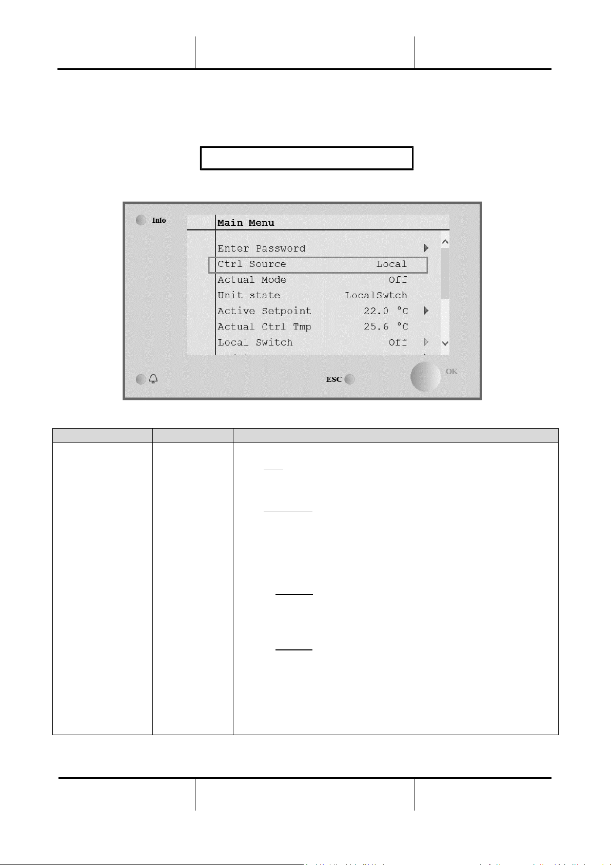
7. Control Source
This item displays the actual control source of the AHU. All possible control source are reported in the table
below.
HMI Path: Main Menu -> Ctrl Source
Main Menu item
Value
Description
Control Source
- Local
- BMS
− Local:
a. HMI: unit control managed directly from the controller
interface or automatically via time scheduler. Refer to Local
Switch page (Section 10) for more details.
b. Room Unit: when Control Source is set to Local, the unit can be
controlled also through the Room Unit device (POL822), if
installed. Refer to Appendix A for more details on Room Unit
control.
− BMS:
a. Modbus: the unit can be controlled by a Modbus Master
device through Modbus protocol, if the corresponding
communication module is installed (POL902). Refer to DEOMOCAH202-18EN for more details.
b. BACnet: the unit can be controlled through BACnet
communication if the corresponding communication module
is installed (POL904/POL908). Refer to D-EOMOCAH10009
for more details.
Page 25
Air Handling Unit
Operation Manual
Air Handling Unit
D-EOMAH00006-20EN
Operation Manual
25
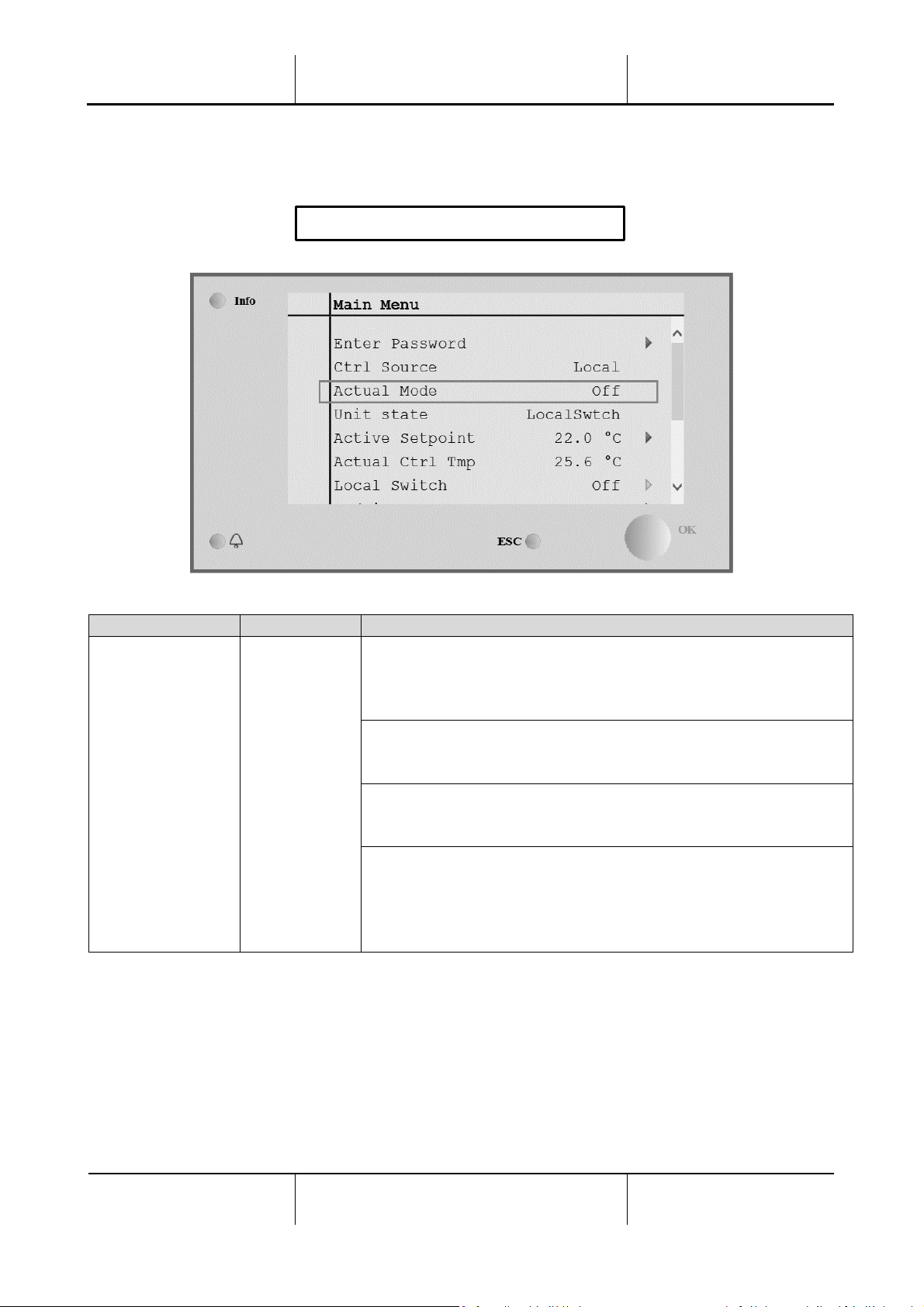
8. Actual Mode
This item (read-only) displays the actual operating mode of the AHU. All possible operating mode are reported
in the table below.
HMI Path: Main Menu -> Actual Mode
Main Menu item
Value
Description
Actual Mode
- Off
- On
- Ventilation
- Economy
Off: AHU in Off mode.
All devices installed on the AHU (fans, cooling/heating coil,
dampers, etc..) are Off.
On: AHU in On mode.
Normal functioning: all controls are active.
Ventilation: AHU in Ventilation mode.
In this mode only fans are running.
Economy: AHU in Economy mode.
Normal functioning: all controls are active, but the AHU works
referring to the Economy set points.
Refer to Setpoints page (Section 12) for more details.
Page 26

Operation Manual
Air Handling Unit
Operation Manual
26
Air Handling Unit
D-EOMAH00006-20EN
9. Unit State
This item (read-only) displays the actual state of the AHU. All possible states are reported in the table below.
HMI Path: Main Menu -> Unit State
Main Menu item
Value
Description
Unit State
- Fire
- Emergency
- Alarm
- Manual
- Panel Switch
- Local Switch
- BMS
- Scheduler
- Ready
- Occupancy
Fire: AHU in Fire alarm state.
The AHU is in this state when a “Fire Alarm” digital input is
detected.
Emergency: AHU in Emergency state
This state indicates that the Emergency button has been pressed.
Alarm: AHU in alarm state.
This state is displayed when an alarm has been detected.
Manual: AHU in Test mode.
The AHU is in this state when Local Switch is set to Test.
Refer to Local Switch page (Section 10) for more details.
Panel Switch: Switch labeled “Enable Switch” located on the
Electrical Box is set to zero.
Local Switch: AHU controlled manually from interface Room Unit or
a Modbus Master device.
Refer to Local Switch (Section 10) and Control Source (Section 6)
pages for more details.
BMS: AHU controlled via Modbus or BACnet.
Scheduler: AHU in On state by Time Scheduler.
Page 27

Air Handling Unit
Operation Manual
Air Handling Unit
D-EOMAH00006-20EN
Operation Manual
27
Main Menu item
Value
Description
Refer to Time Scheduler (Section 14) page for more details
Ready: AHU in Off state by Time Scheduler.
Refer to Time Scheduler (Section 14) page for more details.
Occupancy: AHU in On state by Occupancy function.
Refer to Room Unit page for more details. (Appendix A)
Page 28

Operation Manual
Air Handling Unit
Operation Manual
28
Air Handling Unit
D-EOMAH00006-20EN
10. Active Setpoint
All actual setpoints used by the software to control AHU devices are reported in the Active Setpoint page.
In the Main Menu screen is displayed the actual setpoint used for controlled temperature.
HMI Path: Main Menu -> Active Setpoint
Parameters
Description
Temperature
Display the actual setpoint used for the controlled temperature.
This value is the sum of the basic setpoint (given by Summer/Winter
state) plus the offset set through the Room unit (R.U.), if present.
- Summer mode
Temperature = Cool (+ R.U. Offset, if present)
- Winter mode
Temperature = Heat (+ R.U. Offset, if present)
Supply Fan
Display the actual setpoint value for the supply fan.
This value is the sum of the basic setpoint plus the offset evaluated
by the software for compensation (if a compensation function is
active).
Supply Fan = Supply Fan (+ Comp. Offset, if active)
Return Fan
Display the actual setpoint value for the return fan.
This value is the sum of the basic setpoint plus the offset evaluated
by the software for compensation (if a compensation function is
active).
Return Fan = Return Fan (+ Comp. Offset, if active)
Humidification
Display the actual humidification setpoint.
Dehumidification
Display the actual dehumidification setpoint.
Air Quality
Display the actual air quality setpoint.
Page 29

Air Handling Unit
Operation Manual
Air Handling Unit
D-EOMAH00006-20EN
Operation Manual
29
11. Local Switch
This item is used to control locally the operating mode of the AHU.
NOTE! Any change on this item does not have any effect if the AHU is configured to be controlled by
BMS (i.e. Ctrl Source = BACnet).
HMI Path: Main Menu -> Local Switch
Main Menu item
Value
Description
Local Switch
- Auto
- Off
- On
- Ventilation
- Economy
- Test
Auto: AHU On-Off state is managed by the time scheduler.
Refer to Time Scheduler page for more details.
Off: turn off the AHU.
On: turn on the AHU.
In this mode all controls are active and setpoints related to
temperature regulation and fans control are the normal setpoints.
Refer to Setpoints page (Section 12) to change normal setpoints.
Ventilation: Switch the AHU in ventilation mode.
In this mode only fans are running.
No temperature control is performed.
Economy: Switch the AHU in economy mode.
In this mode all controls are active, but the setpoints related to
temperature regulation and fans control switch from normal
setpoints to economy setpoints.
Refer to Setpoints page (Section 12) to change economy setpoints.
Test: AHU in Test mode.
In this mode every device of the AHU can be manually controlled.
NOTE! This function is only available with service password
entered and the item is visible only if the AHU is OFF.
Page 30

Operation Manual
Air Handling Unit
Operation Manual
30
Air Handling Unit
D-EOMAH00006-20EN
12. Summer/Winter state
The AHU software provides three different options for summer/winter changeover control:
- Automatic changeover based on temperature.
The controller monitors one of the several temperatures available on the AHU (Room, Return or
Outside). The value of this temperature is after compared with two limits (one for summer and one
for winter) and, depending on the result of this comparison, the controller chooses the cool/heat
state for the next period.
- Manually changeover via HMI or Room Unit.
- Changeover managed via BMS.
All information and settings for this control are available in the following HMI page:
HMI Path: Main Menu -> Su/Wi State
The following table explains all items present in the Su/Wi state page and how configure them to obtain the
desired control.
Parameters
Value
Description
Su/Wi chg source
1. Auto
2. HMI
3. BMS
4. Pursuit*
This parameter defines which mode is used to control the
Summer/Winter switch:
1. Auto: changeover is done automatically by the AHU
based on the auto mode configuration
2. HMI: Summer/Winter state is set manually by the HMI
3. BMS: Summer/Winter state is set via BMS
communication.
4. Pursuit*: changeover is performed automatically in
order to reach and maintain the desired temperature
setpoint. Refer to Setpoints page (Section 12) to
change Pursuit mode setpoints.
*Available from Airstream 1.00.A software version and only if
Return or Room temperature control has been selected.
Page 31

Air Handling Unit
Operation Manual
Air Handling Unit
D-EOMAH00006-20EN
Operation Manual
31
Parameters
Value
Description
HMI changeover
- Summer
- Winter
Set actual mode of the AHU if Su/Wi chg source = HMI
Network
changeover
- Summer
- Winter
Display the mode set via BMS.
If the Su/Wi chg source = BMS, this value is the current state of
the AHU.
Current State
- Summer
- Winter
Display the current state in which the AHU is operating.
Auto mode settings:
Tmp Used
- Return
- Room
- Outside
Select the temperature monitored to determine the
Summer/Winter state changeover.
Time constant
0…36000 [h]
Define the frequency at which the check is being performed for
the Summer/Winter changeover in Auto Mode.
Example:
If this parameter is set equal to 6 hours, the controller
maintains the same state (Summer or Winter) for six hours.
After six hours, the controller performs again the check to
determine the next state that will be maintained for next six
hours.
Tmp Damped
-64...64 [°C]
Display the value of temperature stored when automatic
changeover happened.
Su tmp
-64...64 [°C]
Changes over to summer operation when the selected
temperature is greater than this value.
Wi tmp
-64...64 [°C]
Changes over to winter operation when the selected
temperature is less than this value.
Page 32

Operation Manual
Air Handling Unit
Operation Manual
32
Air Handling Unit
D-EOMAH00006-20EN
13. Setpoints
All setpoints of the AHU can be set from the HMI. Depending on the AHU configuration some setpoints can
be available or not.
HMI Path: Main Menu -> Setpoints
Parameters
Value Range
Description
Temperature:
Cool
10..40 [°C]
Cooling temperature setpoint.
(Available when direct Htg/Clg setpoint
control selected)
Heat
10..40 [°C]
Heating temperature setpoint.
(Available when direct Htg/Clg setpoint
control selected)
Cool Economy
Cool..40 [°C]
Cooling temperature setpoint in
Economy mode.
(Available when direct Htg/Clg setpoint
control selected)
Heat Economy
10..Heat [°C]
Heating temperature setpoint in
Economy mode.
(Available when direct Htg/Clg setpoint
control selected)
Central Temp
10..40 [°C]
Central temperature setpoint.
(Available only when temperature
regulation with deadzone control
selected)
Page 33

Air Handling Unit
Operation Manual
Air Handling Unit
D-EOMAH00006-20EN
Operation Manual
33
Band Temp
0..20 [°C]
Deadzone temperature setpoint.
(Available only when temperature
regulation with deadzone control
selected)
Central Temp
Economy
Cool..40 [°C]
Central temperature setpoint in
Economy mode.
(Available only when temperature
regulation with deadzone control
selected)
Band Temp
Economy
10..Heat [°C]
Deadzone temperature setpoint in
Economy mode.
(Available only when temperature
regulation with deadzone control
selected)
Pursuit
10..40 [°C]
Pursuit mode temperature setpoint.
Refer to Summer/Winter state (Section
11) for more details.
(Available from Airstream 0.10.B SW
version and only if Return or Room
temperature control has been selected)
Pursuit Eco
10..40 [°C]
Pursuit mode temperature economy
setpoint.
Refer to Summer/Winter state (Section
11) for more details.
(Available from Airstream 0.10.B SW
version and only if Return or Room
temperature control has been selected)
Pursuit Band
3,5..10 [°C]
Pursuit mode offset temperature
setpoint. This value is
added/subtracted from actual Pursuit
setpoint in order to estimate
Summer/Winter changeover tresholds.
Refer to Summer/Winter state (Section
11) for more details.
(Available from Airstream 0.10.B SW
version and only if Return or Room
temperature control has been selected)
R.U. Offset
-6…6 [°C]
Display the actual offset set through
the room unit.
(Available only with room unit)
Pre-Heating
0..30 [°C]
Temperature threshold for Pre-Heating
control activation.
(Available only if pre-heating control
enabled)
Page 34

Operation Manual
Air Handling Unit
Operation Manual
34
Air Handling Unit
D-EOMAH00006-20EN
Fan Ventilation:
Supply
0..100 [%]
0..5000[Pa]
0..140000[m3/h]
Fans setpoints.
Depending on the control type of the
fan, the setpoint can be expressed in
Percentage [%], Pascal [Pa], Cube
meter per hour [m3/h].
(Not available if fans are controlled in
On/Off mode)
Return
0..100 [%]
0..5000[Pa]
0..140000[m3/h]
Supply Economy
0..100 [%]
0..5000[Pa]
0..140000[m3/h]
Return Economy
0..100 [%]
0..5000[Pa]
0..140000[m3/h]
Supply Defrost
0..100 [%]
0..5000[Pa]
0..140000[m3/h]
Supply fan setpoint in case of defrost of
the condensing unit ERQ
(Available only if fan-defrost limitation
control enabled)
Return Defrost
0..100 [%]
0..5000[Pa]
0..140000[m3/h]
Return fan setpoint in case of defrost of
the condensing unit ERQ
(Available only if fan-defrost limitation
control enabled)
Others:
Dehumidification
- 0…100 [%rH]
- Humidification…100 [%rH] (if
humidification control enabled)
Dehumidification setpoint
(Available only if dehumidification
control enabled)
Humidification
- 0…100 [%rH]
- 0…Dehumidification [%rH] ] (if
dehumidification control enabled)
Humidification setpoint.
(Available only if humidification control
enabled)
Air Quality
0..3000 [ppm]
Air control quality setpoint. Limit of ppm
(parts per million) for the CO2.
(Available only if CO2 control enabled)
Fan fire setpoint
0..100 [%]
Fans setpoints when fire alarm
detected.
(Available only if Fire Alarm enabled)
Page 35

Air Handling Unit
Operation Manual
Air Handling Unit
D-EOMAH00006-20EN
Operation Manual
35
14. I/O Overview
This menu allows the user to monitor all analog/digital inputs and outputs of the controller. The list can be
different for each specific AHU as it depends on the installed components of the unit which are activated
during the commissioning.
HMI Path: Main Menu -> I/O overview
Parameters
Description
Digital inputs
Monitor all digital inputs of the controller.
Digital inputs can be connected to alarm signals coming from different
installed devices in the AHU (Fan, Damper, Pressure Switch, Water
Pump, etc…), or to external switches (Emergency stop, Unit enable).
Analog inputs
Contains the values of all installed sensors: temperature, pressure, air
flow, CO2, humidity.
Digital outputs
Contains the values of all digital outputs used to command the several
devices of the AHU (ERQ on/off, Pump on/off, Fan on/off, etc…).
Analog outputs
Contains the values of all analog outputs used to command different
devices of the AHU (Fan speed, damper opening, percentage of heat
recovery, etc…).
Page 36

Operation Manual
Air Handling Unit
Operation Manual
36
Air Handling Unit
D-EOMAH00006-20EN
15. Time Scheduler
The time scheduler is a function that allows the user to set the time slots at which the AHU can be turned ON
or OFF. If the scheduler is set, the AHU will be turned On/Off automatically by following the time slot
configuration. In the next tables are reported the items of the time scheduler menu and their description.
The time scheduler page contains also the configuration pages for single day time scheduling.
HMI Path: Main Menu -> Time Scheduler
Parameter
Value
Function
TS actual
state
- Off
- On
- Ventilation
- Economy
Actual operating mode from time scheduler function.
Monday
- Active
- Passive
Active if the present day is Monday.
Refer to Day Scheduler (Section 14.1) for more details.
Copy schedule
- Off
- On
Copy Monday schedule to all weekdays.
Tuesday
- Active
- Passive
Active if the present day is Tuesday.
Refer to Day Scheduler (Section 14.1) for more details.
….
….
….
Sunday
- Active
- Passive
Active if the present day is Sunday.
Refer to Day Scheduler (Section 14.1) for more details.
Exception
- Passive
- Active
Active if the present day is an exception day.
Refer to both Day Scheduler (Section 14.1) and Calendar Exception and
Calendar Fix off (Section 14.2) for more details.
Period: Start
Start date for the weekly schedule.
If equals to *,* *.00, weekly schedules is always enabled.
Period: End
End date for the weekly schedule.
If equals to *,* *.00, weekly schedules is never disabled.
Calendar
exception
- Passive
- Active
Active if the present day is an exception day.
Refer to Calendar Exception/Fix off (Section 14.2) for more details.
Page 37

Air Handling Unit
Operation Manual
Air Handling Unit
D-EOMAH00006-20EN
Operation Manual
37
Calendar fix
off
- Passive
- Active
Active if the present day is a fix off day.
Refer to Calendar Exception/Fix off (Section 14.2) for more details.
15.1 Day Scheduler
By entering in each day page, normal or exception, it is possible to set up to 6 time slots.
Parameter
Range
Function
Time 1
00:00
SPECIAL CASE: this entry must always be set to 00:00!
Value 1
- Off
- On
- Ventilation
- Economy
Switching command for Time 1.
Time 2
00:00 - 23:59
Switching time 2
(*:*-> Entry disabled)
Value 2
- Off
- On
- Ventilation
- Economy
Switching command for Time 2.
…
Time 6
00:00 - 23:59
Switching time 6
(*:*-> Entry disabled)
Value 6
- Off
- On
- Ventilation
- Economy
Switching command for Time 6
Below is an example of a day scheduler setting. In this case the AHU will be turned ON from 9.30 until 13.00
and in Economy mode from 14:00 until to 18:40.
Parameter
Value
Time 1
00:00
Value 1
Off
Time 2
09:30
Value 2
On
Time 3
13:00
Value 3
Off
Time 4
14:00
Value 4
Economy
Time 5
18:40
Value 5
Off
Time 6
*:*
Value 6
Off
Page 38

Operation Manual
Air Handling Unit
Operation Manual
38
Air Handling Unit
D-EOMAH00006-20EN
ATTENTION! If a time value is set incorrectly (i.e. it is less than the previous) the AHU will not work properly
and it could be always keep ON or OFF.
15.2 Calendar exception and Calendar fix off
Exception days are defined in the calendar items. These may include a specific date, periods or certain days
of the week.
When an exception day occurs, the “Exception” day scheduler configuration override the weekly schedule.
The time slots at which occurs the exception days can be configured in the “Calendar exception” page. The
“Calendar fix Off” page is a special exception day configuration that allows to switch off the plant at specific
time slots.
Entering in the “Calendar exception” or “Calendar fix off” page allows the user to find the items reported in
the table below.
Parameter
Range
Function
Present value
- Passive
- Active
Displays whether a calendar entry is currently enabled:
− No calendar entry is currently enabled.
− A calendar entry is currently enabled.
Choice-x
- Date
- Range
- Week Day
- Passive
Specifies the entry for the exception:
− Date: a certain day (e.g. Friday).
− Range: a period (e.g. vacation).
− Week Day: a certain day of the week (e.g. every Monday).
− Passive: entries are ignored.
This value should be set last, after the date is entered.
(Start) date
If Choice-x = date -> Enter data for a single day.
If Choice-x = range -> Enter start date for the period.
End date
For Choice-x = range only -> Enter end date for the period.
End date must always be after the start date.
Weekday
For Choice-x = weekday only -> Enter the day of the week.
Example 1: Choice = Date
Only the entry in (start) is relevant:
- (start) date = *,01.01.09
Result: January 1, 2009 is an exception date.
- (Start) date = Mo,*.*.00
Every Monday is an exception day.
- (Start) date = *,*.Evn.00
The days for the entire month are exception day for each even month (February, April, June, August, etc.).
Page 39

Air Handling Unit
Operation Manual
Air Handling Unit
D-EOMAH00006-20EN
Operation Manual
39
Example 2: Choice = Range
The entries in (start) date and end date are relevant:
- (start) date = *,23.06.09 / end date = *,12.07.09.
June 23, 2009 through July 12, 2009 are exception days (e.g. vacation).
- (start) date = *,23.12.00 / end date = *,31.12.00.
December 23 through 31 are exceptions for each year. The entry end date =*,01.01.00 does not work
here, since January 1 is before December 23.
- (start) date = *,23.12.09 / end date = *,01.01.10.
23. December 23, 2009 through January 1, 2010 are exception days.
- (Start) date = *,*.*.00 / -End date = *,*.*.00
Attention! This entry is always enabled! The plant is continuously on exception or off.
Example 3: Choice = Weekday
The entries for week day are relevant.
- Week day = *,Fr,*
Every Friday is an exception day.
- Week day = *,Fr,Evn
Each Friday in even months (February, April, June, August, etc.) is an exception day.
- Week day = *,*,*
Attention! This settings always enables “calendar exception” or “calendar off” days.
Page 40

Operation Manual
Air Handling Unit
Operation Manual
40
Air Handling Unit
D-EOMAH00006-20EN
16. Status/Settings
This menu allows the user to display the actual status and change settings for all the devices available in the
AHU. Depending on AHU configuration some menu item may be available or not.
NOTE! This menu item is only visible with service password entered.
HMI Path: Main Menu -> Status / Settings
Menu item
Description
AHU Device Monitor
Monitor the actual status and load percentage of all devices installed
in the AHU (Dampers, Heat Recovery, Cooling/Heating coils, etc…).
Temperature Control
Contains the specific parameters for general thermoregulation control.
Refer to Temperature Control (Section 15.1) for more details.
Air Quality Control*
Contains all parameters for air quality control monitoring and
parameter settings.
Refer to Air Quality Control (Section 15.2) for more details.
Humidity Control*
Contains all parameters for humidity control monitoring and settings,
for both humidification and dehumidification.
Refer to Humidity Control (Section 15.3) for more details.
Fans
Contains all parameters for fans control monitoring and related
functions.
Refer to Fans Control (Section 15.4) for more details.
Dampers*
Contains all parameters for dampers control monitoring and settings,
for both fresh air and mixing (if installed).
Refer to Dampers Control (Section 15.5) for more details.
Page 41

Air Handling Unit
Operation Manual
Air Handling Unit
D-EOMAH00006-20EN
Operation Manual
41
Menu item
Description
Recovery*
Contains all parameters for the heat recovery device control
monitoring and settings.
Refer to Heat Recovery Control (Section 15.6) for more details.
Cooling*
Contains all parameters for water and generic direct expansion (DX)
cooling coils monitoring and settings.
Refer to Cooling Coil Control (Section 15.7) for more details.
Heating*
Contains all parameters for water and generic direct expansion (DX)
heating coils monitoring and settings.
Refer to Heating Coil Control (Section 15.8) for more details.
Pumps*
Contains all parameters for water pumps monitoring and settings.
Refer to Pumps Control (Section 15.9) for more details.
ERQ*
Contains all parameters for ERQ devices monitoring and settings.
Refer to ERQ Control (Section 15.10) for more details.
Electrical Htg*
Contains all parameters for post-heating control monitoring and
related functions (Electric coil).
Refer to Post-Heating Electrical Control (Section 15.11) for more
details.
Pre-Htg Electrical*
Contains all parameters for pre-heating control monitoring and related
functions (Electric coil).
Refer to Pre-Heating Electrical Control (Section 15.12) for more
details.
Pre-Heating Water*
Contains all parameters for pre-heating control monitoring and related
functions (Water coil).
Refer to Pre-Heating Water Coil Control (Section 15.13) for more
details.
Sensor Settings
Check the status of all sensor installed and set an offset correction on
sensors readings if needed.
Occupancy Time
Set the time value for which the occupancy function is active. This
function will take effect only if the AHU is provided with a room unit
device.
Refer to Appendix A - Room Unit Module for more details.
*Different menu items will be visible depending on AHU configuration.
16.1 Temperature Control
This menu contains the parameters for general thermoregulation control.
HMI Path: Main Menu -> Status / Settings -> Temperature Control
Page 42

Operation Manual
Air Handling Unit
Operation Manual
42
Air Handling Unit
D-EOMAH00006-20EN
Parameter
Default
Range
Description
Active Setpoint
-
-
Display the actual temperature setpoint used for
thermoregulation control.
Actual Ctrl Tmp
-
-
Display the actual controlled temperature value.
Su/Wi state
-
-
Display the actual AHU summer/winter state.
Setpoints
-
-
Contains all AHU temperature setpoints.
Refer to Setpoint page menu (Section 12) for more
details.
Temperatures
-
-
Contains all AHU temperature readings.
Gen Deadzone
1 °C
0.5 - 10 °C
Deadband value between temperature setpoint
and actual controlled temperature for
thermoregulation logics activation.
Max Supply
Tmp
40 °C
20 - 80 °C
Maximum supply temperature value above which
the control starts to limit the load of installed
heating coils.
Min Supply
Tmp
17 °C
0 - 30 °C
Minimum supply temperature value below which
the control starts to limit the load of installed
cooling coils.
Max Supply
Tmp
− Summer = 37 °C
− Winter = 40 °C
20 - 80 °C
Maximum supply temperature value above which
the control starts to limit the load of installed coils.
Min Supply
Tmp
− Summer = 17 °C
− Winter = 17 °C
0 - 30 °C
Minimum supply temperature value below which
the control starts to limit the load of installed coils.
16.2 Air Quality Control
This menu contains all parameters for air quality control monitoring and parameter settings. This function
increases the fan setpoint value by “Max forcing” value in order to reach the air quality setpoint selected.
NOTE! This menu is not visible if no air quality control function is enabled.
HMI Path: Main Menu -> Status / Settings -> Air Quality Control
Parameters
Default
Range
Description
CO2 Conc.
-
- Display the CO2 concentration measured.
Setpoint
800 ppm
0 - 3000 ppm
Set the air quality control setpoint.
Supply fan
Page 43

Air Handling Unit
Operation Manual
Air Handling Unit
D-EOMAH00006-20EN
Operation Manual
43
Parameters
Default
Range
Description
Max forcing
- 0 %
- 0 Pa
- 0 m3/h
- 0..100 %
- 0..9900 Pa
- 0..139900 m3/h
Set the maximum compensation value that will be
added to fan setpoint when air quality control
function is active.
NOTE! This value strictly depends on AHU
application site and desired setpoint, so it must
be changed accordingly from default value if it
is needed to activate the compensation
function.
Measure unit depends on fan control mode
selected.
Actual Comp
-
0 - 100 %
Display the actual fan compensation action
percentage:
- 0% -> No fan SP increasing;
- 50% -> Fan SP increased by “Max forcing”/2;
- 100% -> Fan SP increased by “Max forcing”.
Return fan
Max forcing
- 0 %
- 0 Pa
- 0 m3/h
- 0..100 %
- 0..9900 Pa
- 0..139900 m3/h
Set the maximum compensation value that will be
added to fan setpoint when air quality control
function is active.
NOTE! This value strictly depends on AHU
application site and desired setpoint, so it
must be changed accordingly from default
value if it is needed to activate the
compensation function.
Measure unit depends on fan control mode
selected.
Actual Comp
-
0 - 100 %
Display the actual fan compensation action
percentage:
- 0% -> No fan SP increasing;
- 50% -> Fan SP increased by “Max forcing”/2;
- 100% -> Fan SP increased by “Max forcing”
value.
16.3 Humidity Control
This menu contains all parameters for both humidification and dehumidification control monitoring and
settings.
Page 44

Operation Manual
Air Handling Unit
Operation Manual
44
Air Handling Unit
D-EOMAH00006-20EN
NOTE! This menu is not visible if no humidity control function is enabled.
HMI Path: Main Menu -> Status / Settings -> Humidity Control
Parameters
Default
Range
Description
Relative Hum
- - Display the value coming from the humidity sensor
readings.
Dehum Setpoint*
60 %rH
0 - 100 %rH
Set the dehumidification control setpoint.
Dehum*
-
- Off
- Active
Display the actual state of the dehumidification control
logic.
Win Dehum En*
No
- No
- Yes
Specify if the dehumidification control must be activated
also during “Winter” AHU mode.
Hum Setpoint*
40 %rH
0 - 100 %rH
Set the humidification control setpoint.
Humidifier*
-
0 - 100%
Display the actual controller load command for the
humidification device.
Adiabatic
Recovery*
-
- Off
- On
Display the actual state of the adiabatic recovery function.
Sum Hum En*
No
- No
- Yes
Specify if the humidification control must be activated also
during “Summer” AHU mode.
*Different menu items will be visible depending on AHU configuration.
16.4 Fans Control
This menu contains all parameters and settings for fans control monitoring and related functions.
HMI Path: Main Menu -> Status / Settings -> Fans
Parameters
Default
Range
Description
Setpoints
- - Contains all AHU setpoints related to fan control.
Refer to Setpoint page menu (Section 12) for more details.
Fan Data*
- - Contains additional supply/return fans data.
This menu item is available only for Modular AHU.
Fan
Compensation
-
- None
- Temp.
Display the actual compensation function selected during
AHU commissioning for fans control logic.
Page 45

Air Handling Unit
Operation Manual
Air Handling Unit
D-EOMAH00006-20EN
Operation Manual
45
Parameters
Default
Range
Description
- Co2
- None: no fan compensation function selected;
- Temperature: temperature compensation function
selected.
This function starts to decrease the fan setpoint value
selected by “Max forcing” value only if both heat recovery
and mixing damper devices are at full load, in order to
increase the thermal exchange between airflow and
heating/cooling coils and reach the desired temperature
setpoint.
- Co2: air quality compensation function selected.
This function increases the fan setpoint value selected by
“Max forcing” value in order to reach the air quality
setpoint selected.
Refer to Air Quality Control (Section 15.2) for more
details.
Supply fan
Active Setpoint
- - Display the actual supply fan setpoint that is used in the
control logic (this value represents the sum of all functions
that affect the supply fan setpoint).
Supply
Pressure*
- - Display the value read from the supply fan pressure
sensor.
Supply Air
Flow*
- - Display the value read from the supply fan air flow sensor.
State
-
- Off
- On
Display the actual fan state.
Speed
-
0 - 100 %
Display the actual fan speed.
Delay On Tm
60 s
0 - 36000 s
Set the time delay between fresh/exhaust dampers
opening and fan activation.
Over Run Tm*
180 s
0 - 36000 s
Set the time period after AHU turn off for supply fan postventilation, in order to cool down the electric coils.
This setpoint is available only if an electric coil is installed.
The controller will activate the post-ventilation
function only if the electric coil has been turned on
during AHU operation.
Max forcing*
- 0 %
- 0 Pa
- 0 m3/h
- 0..100 %
- 0..9900 Pa
- 0..139900
m3/h
Set the maximum compensation value that will be added
(Co2 compensation) or subtracted (Temp. compensation)
to fan setpoint when fan compensation function is active.
Page 46

Operation Manual
Air Handling Unit
Operation Manual
46
Air Handling Unit
D-EOMAH00006-20EN
Parameters
Default
Range
Description
Refer to “Fan Compensation” parameter for additional
details.
This value is available only if a fan compensation function
has been selected in configuration.
NOTE! This value strictly depends on AHU
application site and desired setpoint, so it must be
changed accordingly from default value if it is
needed to activate the compensation function.
Measure unit depends on fan control mode selected.
Actual Comp*
-
0 - 100 %
Display the actual fan compensation action percentage:
- 0% -> No fan SP inc/dec;
- 100% -> Fan SP inc/dec by “Max forcing” value.
Refer to “Fan Compensation” parameter for additional
details.
This value is available only if a fan compensation function
has been selected in configuration.
Max Setpnt
Devtn*
30 %
0 - 100 %
Set the percentage deviation between fan setpoint and
sensor reading above which the controller generates a
warning, if this condition is verified for more than “Setpnt
Devtn On Tm” value.
This setpoint is available only if fan deviation alarm
function has been enabled in configuration.
Setpnt Devtn
On Tm*
30 min
0 - 1000 m
Set the time period after which the controller generates a
warning if “Max Setpnt Devtn” condition is verified.
This setpoint is available only if fan deviation alarm
function has been enabled in configuration.
Defrost Setpnt*
- 80 %
Pa
m3/h
- 0..100 %
- 0..5500 Pa
- 0..139900
m3/h
Set fan setpoint in case of ERQ defrost state.
This setpoint is available only if fan-defrost limitation
control has been enabled in configuration.
Return fan
Active Setpoint
- - Display the actual return fan setpoint that is used in the
control logic (this value represents the sum of all functions
that affect the return fan setpoint).
Return
Pressure*
- - Display the value read from the return fan pressure
sensor.
Page 47

Air Handling Unit
Operation Manual
Air Handling Unit
D-EOMAH00006-20EN
Operation Manual
47
Parameters
Default
Range
Description
Return Air
Flow*
- - Display the value read from the return fan air flow sensor.
State
-
- Off
- On
Display the actual fan state.
Speed
-
0 - 100 %
Display the actual fan speed.
Delay On Tm
60 s
0 - 36000 s
Set the time delay between fresh/exhaust dampers
opening and fan activation.
Max forcing*
- 0 %
- 0 Pa
- 0 m3/h
- 0..100 %
- 0..9900 Pa
- 0..139900
m3/h
Set the maximum compensation value that will be added
(Co2 compensation) or subtracted (Temp. compensation)
to fan setpoint when fan compensation function is active.
Refer to “Fan Compensation” parameter for additional
details.
This value is available only if a fan compensation function
has been selected.
NOTE! This value strictly depends on AHU
application site and desired setpoint, so it must be
changed accordingly from default value if it is
needed to activate the compensation function.
Measure unit depends on fan control mode selected.
Actual Comp*
-
0 - 100 %
Display the actual fan compensation action percentage:
- 0% -> No fan SP inc/dec;
- 100% -> Fan SP inc/dec by “Max forcing” value.
Refer to “Fan Compensation” parameter for additional
details.
This value is available only if a fan compensation function
has been selected.
Max Setpnt
Devtn*
30 %
0 - 100 %
Set the percentage deviation between fan setpoint and
sensor reading above which the controller generates a
warning, if this condition is verified for more than “Setpnt
Devtn On Tm” value.
This setpoint is available only if fan deviation alarm
function has been enabled.
Page 48

Operation Manual
Air Handling Unit
Operation Manual
48
Air Handling Unit
D-EOMAH00006-20EN
Parameters
Default
Range
Description
Setpnt Devtn
On Tm*
30 min
0 - 1000 m
Set the time period after which the controller generates a
warning if “Max Setpnt Devtn” condition is verified.
This setpoint is available only if fan deviation alarm
function has been enabled.
Defrost Setpnt*
- 80 %
Pa
m3/h
- 0..100 %
- 0..5500 Pa
- 0..139900
m3/h
Set fan setpoint in case of ERQ defrost state.
This setpoint is available only if fan-defrost limitation
control has been enabled.
Fan fire stpt*
80 %
0 - 100 %
Set fans load when a fire alarm is detected.
This setpoint is available only if the fire alarm function
has been enabled.
Fan fire mode*
Stop
- Stop
- Run Sply
- Run Exh
- Run both
Specify fans state in case of fire alarm.
- Stop: stops both fan;
- Run Supply: only supply fan will be in on state;
- Run Exhaust: only return fan will be in on state;
- Run Supply: both fan will be in on state.
This setpoint is available only if the fire alarm function
has been enabled.
Fast Htg/Clg*
- - Contains all parameters for configuring the fast
heating/cooling function.
Refer to Fast Heating/Cooling (Section 15.4.1) for more
details.
This menu item is available only if the fast heating/cooling
function has been enabled.
*Different menu items will be visible depending on AHU configuration.
16.4.1 Fast Heating/Cooling
This function is used to quickly bring the ambient temperature at the setpoint value during AHU startup. It
maintains an high value of the supply fan setpoint until the temperature reaches the target value; after that,
the fan speed is decreased linearly until it reaches the normal operation fan setpoint.
NOTE! the controlled temperature is the return or room temperature.
In the following table are reported all parameters available in the interface to personalize the behavior of
this function:
Page 49

Air Handling Unit
Operation Manual
Air Handling Unit
D-EOMAH00006-20EN
Operation Manual
49
Parameter
Default
Range
Description
Spl-Fan SP Incr
25%
0 - 50%
This parameter indicates the value added to the supply fan
setpoint (in % of normal setpoint) during fast
heating/cooling.
Strt Tmp Err
5 °C
0 - 30 °C
The fast heating/cooling function is activated only if at the
startup of the AHU the difference between the actual
temperature setpoint and the controlled temperature is
higher than this parameter.
Off Tmp Err
1 °C
0 - 30 °C
When the difference between the actual temperature
setpoint and the controlled temperature become less than
this parameter, the fast heating/cooling function starts to
decrease the supply fan speed.
Off Ramp Time
120 sec
0 - 1200
sec
This parameter sets the time used by the fast heating/cooling
function to decrease the supply fan setpoint to normal
setpoint.
16.5 Dampers Control
This menu contains all parameters for dampers control monitoring and settings, for both fresh air and mixing
dampers (if installed).
HMI Path: Main Menu -> Status / Settings -> Dampers
Parameters
Default
Range
Description
Fresh Air Dmp
Command
-
- Off
- On
Display the actual controller command state for the fresh
air dampers.
Off delay
10 s
0 - 36000 s
Specify the time delay between an AHU turn off command
and fresh air dampers closing.
Mixing Dmp
Mix dmpr out*
-
0 - 100 %
Display the actual mixing damper load percentage.
- Modular AHU:
0% -> Full Close
100% -> Full Open
- Professional AHU:
0% -> Full Open
100% -> Full Close
Min fresh air*
20 %
0 - 100 %
Set the minimum fresh air damper opening percentage
when the mixing damper is installed.
Page 50

Operation Manual
Air Handling Unit
Operation Manual
50
Air Handling Unit
D-EOMAH00006-20EN
Parameters
Default
Range
Description
Delta*
2 %
0.5 - 30 %
Set the percentage of opening/closing steps given to the
mixing damper at every “Control Rate” period.
Control Rate*
5 s
0 - 120 s
Set the time period at which the control rate step “Delta”
is given to the mixing damper.
Reference Tmp*
Return
- Return
- Room**
Specify the temperature used for mixing damper
thermoregulation control logic.
** Selectable only if a Room Unit device is installed.
* These menu items are available only if the Mixing damper is installed.
16.6 Heat Recovery Control
This menu contains all parameters for the heat recovery device control monitoring and settings.
NOTE! This menu is not visible if it is not installed any heat recovery device in the AHU.
HMI Path: Main Menu -> Status / Settings -> Recovery
Parameters
Default
Range
Description
Command
-
- Off
- On
Display the actual controller command state for heat
recovery device.
Hrec output*
-
0 - 100 %
Display the actual heat recovery device load percentage.
Delta*
2 %
0.5 - 30 %
Set the percentage of increase/decrease load steps given
to the heat recovery device at every “Control Rate”
period.
Control Rate*
5 s
0 - 120 s
Set the time period at which the control rate step “Delta”
is given to the heat recovery device.
Reference Tmp*
Return
- Return
- Room**
Specify the temperature used for heat recovery device
thermoregulation control logic.
** Selectable only if a Room Unit device is installed.
* These menu items are available only if the control of the Recovery device has been configured as modulating.
16.7 Cooling Coil Control
This menu contains all parameters for water and generic direct expansion (DX) cooling coils monitoring and
settings.
NOTE! This menu is not visible if there are no water or DX cooling coils.
HMI Path: Main Menu -> Status / Settings -> Cooling
Page 51

Air Handling Unit
Operation Manual
Air Handling Unit
D-EOMAH00006-20EN
Operation Manual
51
Parameters
Default
Range
Description
Control Out
-
0 - 100%
Display the actual controller load command for the cooling
coil.
- Water coil -> this value represents the opening
percentage of the valve;
- DX coils -> this value represents the internal control
reference used to activate the DX steps (see
parameters below for additional details).
DX steps stpt
Min off time*
120 s
5 - 600 s
Set the delay time for the activation of the DX coils steps.
Start stage 1*
20 %
0 - 100 %
Specify the “Control Out” percentage at which the DX step
1 will be activated.
Start stage 2*
40 %
0 - 100 %
Specify the “Control Out” percentage at which the DX step
2 will be activated.
Start stage 3*
80 %
0 - 100 %
Specify the “Control Out” percentage at which the DX step
3 will be activated.
Stage hys off*
10 %
1 - 100 %
Specify the turn off hysteresis of DX steps. Example:
“Stage hys off” = 10% & “Start stage 2” = 40% ->
DX step 2 turn off at “Control Out” = 30%
Min Temp Lim
-
- Passive
- Active
Display the actual status of the minimum supply
temperature limitation logic.
The supply temperature limitation logic is always
enabled by default.
* These menu items are available only if a direct expansion device has been selected as cooling coil.
16.8 Heating Coil Control
This menu contains all parameters for water and generic direct expansion (DX) heating coils monitoring and
settings.
NOTE! This menu is not visible if there are no water or DX heating coils.
HMI Path: Main Menu -> Status / Settings -> Heating
Parameters
Default
Range
Description
Control Out
-
0 - 100%
Display the actual controller load command for the
heating coil.
- Water coil -> this value represents the opening
percentage of the valve;
Page 52

Operation Manual
Air Handling Unit
Operation Manual
52
Air Handling Unit
D-EOMAH00006-20EN
Parameters
Default
Range
Description
- DX coils -> this value represents the internal control
reference used to activate the DX steps (see
parameters below for additional details).
DX steps stpt
Start stage 1*
20 %
0 - 100 %
Specify the “Control Out” percentage at which the DX step
1 will be activated.
Start stage 2*
40 %
0 - 100 %
Specify the “Control Out” percentage at which the DX step
2 will be activated.
Start stage 3*
80 %
0 - 100 %
Specify the “Control Out” percentage at which the DX step
3 will be activated.
Stage hys off*
10 %
1 - 100 %
Specify the turn off hysteresis of DX steps. Following an
example:
“Stage hys off” = 10% & “Start stage 2” = 40% ->
DX step 2 turn off at “Control Out” = 30%
Frost sp
100 %
50 - 100 %
Specify the valve opening percentage in case of frost
switch alarm.
This menu item is available only if the frost switch has been
configured.
Frost Off Delay
5 min
3 - 30 min
Specify the delay time between frost switch mechanical
deactivation and corresponding alarm auto-reset.
This menu item is available only if the frost switch has been
configured.
ERQ/Wtr priority
Switch Tmp
10 °C
-20..40 °C
When the ERQ and water coil priority is set to Auto, the
activation sequence is automatically determined from the
comparison between “Switch Tmp” and the outside air
temperature:
Tout > “Switch Tmp” -> ERQ first
Tout < “Switch Tmp” -> Water first
This menu item is available only if the ERQ/Wtr priority has
been configured as Auto
Max Temp Lim
-
- Passive
- Active
Display the actual status of the maximum supply
temperature limitation logic.
The supply temperature limitation logic is always
enabled by default.
Page 53

Air Handling Unit
Operation Manual
Air Handling Unit
D-EOMAH00006-20EN
Operation Manual
53
Parameters
Default
Range
Description
* These menu items are available only if a direct expansion device has been selected as heating coil.
16.9 Pumps Control
This menu contains all parameters for water pumps monitoring and settings.
NOTE! This menu is not visible if there are no pumps installed in the AHU.
HMI Path: Main Menu -> Status / Settings -> Pumps
Parameters
Default
Range
Description
Cooling pump
Cooling pump*
-
- Off
- On
Display the actual controller command state for the
cooling pump.
Min run time*
180 s
0 - 36000 s
Specify the time delay between an AHU turn off command
and cooling pump off command.
Heating pump
Heating pump*
-
- Off
- On
Display the actual controller command state for the
heating pump.
Min run time*
180 s
0 - 36000 s
Specify the time delay between an AHU turn off command
and heating pump off command.
*Different menu items will be visible depending on pump type configuration.
16.10 ERQ Control
This menu contains all parameters for ERQ devices monitoring and settings.
NOTE! This menu is not visible if there are no ERQ installed in the AHU.
HMI Path: Main Menu -> Status / Settings -> ERQ
16.10.1 ERQ Status
Parameters
Default
Range
Description
State
ERQ #1
-
- Not Ready
- Ready
Display the actual state of ERQ 1
…
ERQ #4
-
- Not Ready
- Ready
Display the actual state of ERQ 4
Page 54

Operation Manual
Air Handling Unit
Operation Manual
54
Air Handling Unit
D-EOMAH00006-20EN
Parameters
Default
Range
Description
ERQ current operation
ERQ #1
-
- Off
- On
- Defrost
Display the actual operating mode of ERQ 1
…
ERQ #4
-
- Off
- On
- Defrost
Display the actual operating mode of ERQ 4
Time to Ready
ERQ #1
- Display the time before the ERQ 1 becomes Ready again
…
ERQ #4
- Display the time before the ERQ 4 becomes Ready again
Load
ERQ #1
-
0 - 100 %
Display the actual load percentage of ERQ 1
…
ERQ #4
-
0 - 100 %
Display the actual load percentage of ERQ 4
Signal 0-10V
ERQ #1
-
0 - 10V
Display the actual controller voltage output for ERQ 1
…
ERQ #4
-
0 - 10V
Display the actual controller voltage output for ERQ 4
16.10.2 ERQ Settings
Parameters
Default
Range
Description
Startup DT
2 °C
1 - 10 °C
Set the temperature threshold between the setpoint and
the actual controlled temperature for the startup of a new
ERQ (this value represent the deadzone for the activation
of the ERQs).
In addition, this condition must be verified for at least
“Startup Time”.
NOTE! This value depends on the temperature that
is being controlled. If the controlled temperature
is the supply one, it is advisable to not set this
value lower than default, in order to avoid
undesired control oscillation.
The ERQs activation sequence follows a control
logic that evaluates the actual running hours and
the number of starts for each ERQ, in order to
Page 55

Air Handling Unit
Operation Manual
Air Handling Unit
D-EOMAH00006-20EN
Operation Manual
55
Parameters
Default
Range
Description
equalize their workload. This means that the
sequence does not necessarily follows the ERQs
sequence number (1 to 4).
Startup Time
60 sec
0 - 3600 s
Set the time period for which the ERQ activation condition
“Startup DT” must be verified for the startup of the ERQs.
Interval Time
Startup
360 sec
0 - 3600 s
Interval time between the startup of one ERQ and the
next.
Shutdown DT
3.5 °C
1 - 10 °C
Set the temperature threshold between the setpoint and
the actual controlled temperature for the shutdown of an
ERQ (this value represents the deadzone for the
deactivation of the ERQs).
In addition, this condition must be verified for at least
“Shutdown Time”.
NOTE! This value depends on the temperature that
is being controlled. If the controlled temperature
is the supply one, it is advisable to not set this
value lower than default, in order to avoid
undesired control oscillation.
The ERQs shutdown sequence follows a control
logic that evaluates the actual running hours and
the number of starts for each ERQ, in order to
equalize their workload. This means that the
sequence does not necessarily follows the ERQs
sequence number (4 to 1).
Shutdown Time
360 sec
0 - 3600 s
Set the time period for which the ERQ deactivation
condition “Shutdown DT” must be verified for the
shutdown of the ERQs.
Min Load Limit
0 %
0 -100 %
Minimum load percentage that the last ERQ active must
reaches before it is turned off
NOTE! The last ERQ follows both conditions
“Shutdown DT” & “Min Load Limit”.
Interval Time
Shutdown
360 sec
0 - 3600 s
Interval time between the shutdown of one ERQ and the
next.
Lower Limit Te
0 °C
-64..64 °C
Lower limit for the Evaporating temperature.
NOTE! This parameter must match the one that is
set on Daikin Controlbox (Mode 51, Settings 1). If
one is changed, the other must be set accordingly.
Upper Limit Te
15 °C
-64..64 °C
Upper limit for the Evaporating temperature.
Page 56

Operation Manual
Air Handling Unit
Operation Manual
56
Air Handling Unit
D-EOMAH00006-20EN
Parameters
Default
Range
Description
NOTE! This parameter must match the one that is
set on Daikin Controlbox (Mode 51, Settings 1). If
one is changed, the other must be set accordingly.
Lower Limit Tc
35 °C
-64..64 °C
Lower limit for the Condensing temperature.
NOTE! This parameter must match the one that is
set on Daikin Controlbox (Mode 51, Settings 0). If
one is changed, the other must be set accordingly.
Upper Limit Tc
49 °C
-64..64 °C
Upper limit for the Condensing temperature.
NOTE! This parameter must match the one that is
set on Daikin Controlbox (Mode 51, Settings 0). If
one is changed, the other must be set accordingly.
Time Off
60 sec
0 - 3600 s
Time between two ERQ load control pulses.
Threshold 1
40 %
0 -100 %
Minimum load that must reaches the first ERQ before it is
turned on the second ERQ.
Threshold 2
40 %
0 -100 %
Minimum load that must reaches the second ERQ before
it is turned on the third ERQ.
Threshold 3
40 %
0 -100 %
Minimum load that must reaches the third ERQ before it is
turned on the fourth ERQ.
16.11 Post-Heating Control
This menu contains all parameters for electrical or water post-heating control monitoring and settings.
NOTE! This menu is not visible if there is not a post-heating coil installed in the AHU.
HMI Path: Main Menu -> Status / Settings -> Post Heat
Parameters
Default
Range
Description
Post Htg*
-
- Off
- Step 1
- Step 2
Display the actual controller command for the electrical
heating coil.
Control Out
-
0 - 100%
Display the actual controller load command for the
electrical heating coil.
- Modulating coil -> this value represents the load
percentage of the electrical heating coil;
- Step coil -> this value represents the internal control
reference used to activate the electrical heating stages
(see parameters below for additional details).
Page 57

Air Handling Unit
Operation Manual
Air Handling Unit
D-EOMAH00006-20EN
Operation Manual
57
Parameters
Default
Range
Description
Start stage 1*
20 %
0 - 100 %
Specify the “Control Out” percentage at which the post
heating step 1 will be activated.
Start stage 2*
40 %
0 - 100 %
Specify the “Control Out” percentage at which the post
heating step 2 will be activated.
Stage hys off*
10 %
1 - 100 %
Specify the turn off hysteresis of post heating steps.
Example:
“Stage hys off” = 10% & “Start stage 2” = 40% ->
Electrical heating step 2 turn off at “Control Out” = 30%
Max Temp Lim
- Passive
- Active
Display the actual status of the maximum supply
temperature limitation logic.
The supply temperature limitation logic is always
enabled by default.
* These menu items are available only if the device is a step post-heater.
16.12 Pre-Heating Electrical Control
This menu contains all parameters for electrical pre-heating control monitoring and settings.
NOTE! This menu is not visible if there is not an electrical pre-heater installed in the AHU.
HMI Path: Main Menu -> Status / Settings -> Pre-Htg Electrical
Parameters
Default
Range
Description
PreHtgPos
- AftMxg
- AftMxg
- BefMxg
Set the position of the electrical pre heating coil in order
to regulate properly the mixing damper during the electric
heater cool down.
Pre-Heating
Temperaure
- - Display the pre-heating temperature sensor reading.
Setpoint
10 °C
0 - 30 °C
Set the pre-heating temperature setpoint.
Pre Htg Elect
-
- Off
- Step 1
- Step 2
Display the actual controller command for the electrical
pre-heating coil.
Control Out
-
0 - 100%
Display the actual controller load command for the
electrical pre-heating coil.
This value represents the internal control reference used
to activate the electrical pre-heating stages (see
parameters below for additional details).
Start stage 1
20 %
0 - 100 %
Specify the “Control Out” percentage at which the
electrical pre-heating step 1 will be activated.
Page 58

Operation Manual
Air Handling Unit
Operation Manual
58
Air Handling Unit
D-EOMAH00006-20EN
Parameters
Default
Range
Description
Start stage 2
40 %
0 - 100 %
Specify the “Control Out” percentage at which the
electrical pre-heating step 2 will be activated.
Stage hys off
10 %
1 - 100 %
Specify the turn off hysteresis of electrical pre-heating
steps. Example:
“Stage hys off” = 10% & “Start stage 2” = 40% ->
Electrical pre-heating step 2 turn off at “Control Out” =
30%
Rec Prot Active
-15 °C
-30..20 °C
Specify the outside temperature threshold below which
the pre-heater will be activated in order to prevent the
heat recovery device freezing.
16.13 Pre-Heating Water Control
This menu contains all parameters for pre-heating water coil control monitoring and settings.
NOTE! This menu is not visible if there is not a pre-heater water coil installed in the AHU.
HMI Path: Main Menu -> Status / Settings -> Pre-Htg Water
Parameters
Default
Range
Description
Pre-Heating
Temperaure
- - Display the pre-heating temperature sensor reading.
Setpoint
10 °C
0 - 30 °C
Set the pre-heating temperature setpoint.
Control Output
-
0 - 100%
Display the actual controller load command for the
electrical pre-heating coil.
This value represents the internal control reference used
to activate the electrical pre-heating stages (see
parameters below for additional details).
Rec Prot Active
-15 °C
-30..20 °C
Specify the outside temperature threshold below which
the pre-heater will be activated in order to prevent the
heat recovery device freezing.
Page 59

Air Handling Unit
Operation Manual
Air Handling Unit
D-EOMAH00006-20EN
Operation Manual
59
Page 60

Operation Manual
Air Handling Unit
Operation Manual
60
Air Handling Unit
D-EOMAH00006-20EN
17. Alarm handling
This menu can be used to visualize and manage every alarm occurrence.
HMI Path: Main Menu -> Alarm handling
Depending on the severity of the alarm, the AHU can assume two different behaviors:
- Not Critical Alarm: the AHU normal functioning is not affected, reporting only on the interface
the alarm condition. An example of not critical alarm is the indication of a dirty filter.
- Critical Alarm: the AHU switches to OFF state and controls remain locked until the alarm
condition is restored. An example of critical alarm is a fan fault.
17.1 Alarm restore
When an alarm is displayed on the controller, follow this procedure to go back to the normal functioning:
1. Refer to “Alarm list” (Section 17.2) for an explanation of the alarm and for the indication about
resolving the alarm condition.
2. When the alarm condition is restored, an alarm acknowledge command is needed on the controller:
HMI Path: Main menu -> Alarm handling -> Alarm list -> Acknowledge = Execute
3. If the alarm condition is correctly restored after the “Execute” command, the AHU goes back to
normal functioning.
Page 61

Air Handling Unit
Operation Manual
Air Handling Unit
D-EOMAH00006-20EN
Operation Manual
61
17.2 Alarm list
Next table shows all alarm strings that appears on screen when an alarm occurs, with the respective causes
and solutions list.
Alarm String
Description
Possible causes & solutions
Outside temp:
-no sensor
-over range
-under range
-shortd loop
-config err
Error condition on the
outside temperature
sensor:
measured temperature
out of the allowable
range or error
condition on the
sensor.
Error
Causes
Solutions
no sensor
Sensor not connected
Check the wiring connection
of the temperature sensor
with the controller or (if it is
powered) with the electrical
power
over range
Measured value over
max limit
If the measured value is
wrong replace the sensor
under
range
Measured value under
range
If the measured value is
wrong replace the sensor
shortd
loop
The sensor could be
broken
Disconnect the temperature
sensor from the controller
and measure the resistance
value of the sensor. Refer to
the datasheet of the sensor
for the resistance nominal
value of sensor
config err
The sensor not
corresponds to the
sensor type set in the
software for the
specific input of the
controller
Check if the sensor is
connected to the correct pin
of the controller
Room temp:
-no sensor
-over range
-under range
-shortd loop
-config err
Error condition on the
room air temperature
sensor:
measured temperature
out of the allowable
range or error
condition on the
sensor.
Error
Causes
Solutions
no sensor
Sensor not connected
Check the wiring connection
of the temperature sensor
with the controller or (if it is
powered) with the electrical
power
over range
Measured value over
max limit
If the measured value is
wrong replace the sensor
under
range
Measured value under
range
If the measured value is
wrong replace the sensor
shortd
loop
The sensor could be
broken
Disconnect the temperature
sensor from the controller
and measure the resistance
value of the sensor. Refer to
Page 62

Operation Manual
Air Handling Unit
Operation Manual
62
Air Handling Unit
D-EOMAH00006-20EN
Alarm String
Description
Possible causes & solutions
the datasheet of the sensor
for the nominal resistance.
config err
The sensor not
corresponds to the
sensor type set in the
software for the
specific input of the
controller
Check if the sensor is
connected to the correct pin
of the controller
Return temp:
-no sensor
-over range
-under range
-shortd loop
-config err
Error condition on the
return air temperature
sensor:
measured temperature
out of the allowable
range or error
condition on the
sensor.
Error
Causes
Solutions
no sensor
Sensor not connected
Check the wiring connection
of the temperature sensor
with the controller or (if it is
powered) with the electrical
power
over range
Measured value over
max limit
If the measured value is
wrong replace the sensor
under
range
Measured value under
range
If the measured value is
wrong replace the sensor
shortd
loop
The sensor could be
broken
Disconnect the temperature
sensor from the controller
and measure the resistance
value of the sensor. Refer to
the datasheet of the sensor
for the resistance nominal
value of sensor
config err
The sensor not
corresponds to the
sensor type set in the
software for the
specific input of the
controller
Check if the sensor is
connected to the correct pin
of the controller
Supply temp:
-no sensor
-over range
-under range
-shortd loop
-config err
Error condition on the
supply air temperature
sensor:
measured temperature
out of the allowable
range or error
condition on the
sensor.
Error
Causes
Solutions
no sensor
Sensor not connected
Check the wiring connection
of the temperature sensor
with the controller or (if it is
powered) with the electrical
power
over range
Measured value over
max limit
If the measured value is
wrong replace the sensor
Page 63

Air Handling Unit
Operation Manual
Air Handling Unit
D-EOMAH00006-20EN
Operation Manual
63
Alarm String
Description
Possible causes & solutions
under
range
Measured value under
range
If the measured value is
wrong replace the sensor
shortd
loop
The sensor could be
broken
Disconnect the temperature
sensor from the controller
and measure the resistance
value of the sensor. Refer to
the datasheet of the sensor
for the resistance nominal
value of sensor
config err
The sensor not
corresponds to the
sensor type set in the
software for the
specific input of the
controller
Check if the sensor is
connected to the correct pin
of the controller
Pre-Heating temp:
-no sensor
-over range
-under range
-shortd loop
-config err
Error condition on the
pre-heating air
temperature sensor:
measured temperature
out of the allowable
range or error
condition on the
sensor.
Error
Causes
Solutions
no sensor
Sensor not connected
Check the wiring connection
of the temperature sensor
with the controller or (if it is
powered) with the electrical
power
over range
Measured value over
max limit
If the measured value is
wrong replace the sensor
under
range
Measured value under
range
If the measured value is
wrong replace the sensor
shortd
loop
The sensor could be
broken
Disconnect the temperature
sensor from the controller
and measure the resistance
value of the sensor. Refer to
the datasheet of the sensor
for the resistance nominal
value of sensor
config err
The sensor not
corresponds to the
sensor type set in the
software for the
specific input of the
controller
Check if the sensor is
connected to the correct pin
of the controller
Causes
Solutions
Page 64

Operation Manual
Air Handling Unit
Operation Manual
64
Air Handling Unit
D-EOMAH00006-20EN
Alarm String
Description
Possible causes & solutions
Heating Pump:
Alarm
Heating pump possible
malfunction.
This alarm occurs when
the water pump
communicate to the
controller an alarm
condition.
The alarm signal of the water
pump is not connected to the
controller
Check the wiring connection
between the input
“Cooling/Heating coil pump
alarm” (water coils combined) or
“Heating coil pump alarm” (water
coils separated or only a heating
water coil present) of the
controller and alarm output of the
pump
The pump is in a fault state
- Refer to troubleshooting of the
water pump
- Check the electrical connection
of the pump
- Replace the pump if broken
Cooling Pump:
Alarm
Cooling pump possible
malfunction.
This alarm occurs when
the water pump
communicate to the
controller an alarm
condition.
Causes
Solutions
The alarm signal of the water
pump is not connected to the
controller
Check the wiring connection
between the input
“Cooling/Heating coil pump
alarm” of the controller and alarm
output of the pump
The pump is in a fault state
- Refer to troubleshooting of the
water pump
- Check the electrical connection
of the pump
- Replace the pump if broken
Supply filter:
Alarm
[Professional]
Supply filter fault. Filter
dirty.
This alarm occurs when
the differential
pressure switch of the
filter detects a
pressure difference
pressure between
input and output of the
filter.
Causes
Solutions
The filter is dirty
Change the filter
The pressure switch is not
connected
Check the wiring connection of the
pressure switch with the
controller.
Check the electrical power of the
differential pressure switch
The pressure switch is broken
Replace the pressure switch
Return filter:
Alarm
[Professional]
Return filter fault.
Filter dirty.
Causes
Solutions
The filter is dirty
Change the filter
Page 65

Air Handling Unit
Operation Manual
Air Handling Unit
D-EOMAH00006-20EN
Operation Manual
65
Alarm String
Description
Possible causes & solutions
This alarm occurs when
the differential
pressure switch of the
filter detects a
pressure difference
pressure between
input and output of the
filter.
The pressure switch is not
connected
- Check the wiring connection of
the pressure switch with the
controller.
- Check the electrical power of the
differential pressure switch.
The pressure switch is broken
Replace the pressure switch
Filter: Alarm
[Modular]
Supply or Return filter
fault. Filter dirty.
This alarm occurs when
the differential
pressure switch of the
filter detects a
pressure difference
pressure between
input and output of the
filter.
Causes
Solutions
The filter is dirty
Change the filter
The pressure switch is not
connected
- Check the wiring connection of
the pressure switch with the
controller
- Check the electrical power of the
differential pressure switch
The pressure switch is broken
Replace the pressure switch
Cooling DX: Alarm
This alarm occurs when
the alarm signal from
the external
condensing unit is
active
Causes
Solutions
The alarm signal of the
condensing unit is not
connected to the controller
Check the wiring connection
between the input “DX Coil step
#1 (#2, or #3) Alarm” of the
controller and alarm output of the
condensing unit
The condensing unit is in a fault
state
- Refer to troubleshooting of the
condensing unit
- Check the electrical connection
of the condensing unit
Supply fan: Alarm
Differential pressure
switch of the supply
fan active or fan
overload.
This alarm occurs when
the differential
pressure switch of the
supply fan detects a
pressure difference too
Causes
Solutions
The pressure switch is not
connected
Check the wiring connection of the
pressure switch
The belt is broken
Change the belt
The pressure switch is broken
Replace the pressure switch
The fan is broken
Replace the fan
Page 66

Operation Manual
Air Handling Unit
Operation Manual
66
Air Handling Unit
D-EOMAH00006-20EN
Alarm String
Description
Possible causes & solutions
high before and after
the supply fan or if the
fan is in overload.
The fan is in overload
Refer to the troubleshooting of
the fan
Return fan: Alarm
Differential pressure
switch of the return fan
active or fan overload.
This alarm occurs when
the differential
pressure switch of the
return fan detects a
pressure difference too
high before and after
the supply fan or if the
fan is in overload.
Causes
Solutions
The pressure switch is not
connected
Check the wiring connection of the
pressure switch
The belt is broken
Change the belt
The pressure switch is broken
Replace the pressure switch
The fan is broken
Replace the fan
The fan is in overload
Refer to the troubleshooting of
the fan
Supply Fan
Deviation Alm:
Alarm
Setpoint deviation
alarm on the supply
fan.
This alarm occurs when
fan actual controlled
value (Pa or m3/h)
differs from the
setpoint for a
predefined period.
Causes
Solutions
Supply fan is far from the set
point for a predefined period
Check supply fan condition
Return Fan
Deviation Alm:
Alarm
Setpoint deviation
alarm on the return
fan.
This alarm occurs when
fan actual controlled
value (Pa or m3/h)
differs from the
setpoint for a
predefined period.
Causes
Solutions
Return fan is far from the set
point for a predefined period
Check return fan condition
Causes
Solutions
Page 67

Air Handling Unit
Operation Manual
Air Handling Unit
D-EOMAH00006-20EN
Operation Manual
67
Alarm String
Description
Possible causes & solutions
Retrn Hum rel:
under range
Return/Room air
humidity over limit or
error condition on the
air humidity sensor
The humidity sensor is not
connected
Check the wiring connection of the
humidity sensor
The humidity sensor is broken
Replace the humidity sensor
Air qual (CO2):
Alarm
Air quality alarm,
percentage of CO2 too
high. This alarm occurs
when the value of CO2
is out the allowable
range, or error
condition in the air
quality sensor
Causes
Solutions
The percentage of CO2 in the air
is too high
Modify the settings of the AHU to
reduce the percentage of CO2:
- Increase supply fan speed
The air quality sensor is not
connected
Check the wiring connection of the
air quality sensor
The air quality sensor is broken
Replace the air quality sensor
Electrical Heating:
Alarm
Electrical heating
device possible
malfunction. This alarm
occurs when the
electrical heating
device communicate to
the controller an alarm
condition through the
digital input “Electric
Heaters Overload”
Causes
Solutions
The Electrical heating device is
broken
Replace the Electrical heating
device
The Electrical heating device is
not connected
Check the wiring connection of the
Electrical heating device
The Electrical heating device is
in over temperature
Check if there are some airflow
problems before resetting the
alarm
Supply press:
under range
[Professional]
Problem with the
supply air pressure
sensor
Causes
Solutions
Supply pressure sensor not
connected
Check the wiring connection of the
supply sensor. Check the electrical
power of the device
Supply pressure sensor broken
Replace the sensor
Return press:
under range
[Professional]
Problem with the
return air pressure
sensor
Causes
Solutions
Return pressure sensor not
connected
Check the wiring connection of the
return sensor. Check the electrical
power of the device
Return pressure sensor broken
Replace the sensor
Rtrn tmp fire
alarm: Alarm
Causes
Solutions
Presence of fire
Page 68

Operation Manual
Air Handling Unit
Operation Manual
68
Air Handling Unit
D-EOMAH00006-20EN
Alarm String
Description
Possible causes & solutions
Return air temperature
too high, possible
presence of fire
Return temperature sensor
broken
Verify if in the alarm list there is
some alarm related to the return
temperature sensor and in this
case refer to it
Supply tmp fire
alm: Alarm
Supply air temperature
too high, possible
presence of fire
Causes
Solutions
Presence of fire
Supply temperature sensor
broken
Verify if in the alarm list there is
some alarm related to the supply
temperature sensor and in this
case refer to it
Fire alarm: Alarm
Fire alarm active.
This alarm occurs when
the fire detector device
detects the presence of
fire
Causes
Solutions
Presence of fire
If no fire is present, the fire
alarm system could be broken
Check the Fire alarm system
Heating Frost:
Frost
This alarm occurs when
the external unit
communicate to the
controller (through the
digital input “Frost
Switch”) that there
could be ice on the
exchanger of the
external unit
Causes
Solutions
No heating from the exchanger
Check hydraulic circuits and his
temperature, 3way valve, external
unit
Outside temperature very low
The alarm will auto-reset when
“Frost Switch” deactivates. If this
alarm occurs several times, try to
increase “Frost sp” or “Frost Off
Delay” (Refer to Section 15.8)
Recovery: Alarm
[Modular]
This alarm occurs when
the Heat Wheel
recovery device
communicate to the
controller (through the
digital input “Heat
Wheel Alarm”) that an
alarm state has been
detected
Causes
Solutions
Error on the Heat Wheel
Check the operating manual of the
Heat Wheel
Causes
Solutions
Page 69

Air Handling Unit
Operation Manual
Air Handling Unit
D-EOMAH00006-20EN
Operation Manual
69
Alarm String
Description
Possible causes & solutions
I/O Extension
module: Alarm
Communication
malfunction between
the controller and an
expansion module
One or more expansion
modules are not connected to
the controller
Check the wiring connection
between the expansion modules
and the controller
One or more expansion
modules are broken
Change the expansion module
One or more expansion
modules are not configured
properly
Change the DIP switch value (refer
to the wiring diagram)
ERQ 1 alarm :
Alarm
Digital input related to
the ERQ 1 is closed
Causes
Solutions
Error on the ERQ
Check the operating manual of the
ERQ
ERQ 2 alarm :
Alarm
Digital input related to
the ERQ 2 is closed
Causes
Solutions
Error on the ERQ
Check the operating manual of the
ERQ
ERQ 3 alarm :
Alarm
Digital input related to
the ERQ 3 is closed
Causes
Solutions
Error on the ERQ
Check the operating manual of the
ERQ
ERQ 4 alarm :
Alarm
Digital input related to
the ERQ 4 is closed
Causes
Solutions
Error on the ERQ
Check the operating manual of the
ERQ
Emergency Stop:
Alarm
Digital input related to
Emergency stop button
is open
Causes
Solutions
Emergency stop button pressed
Release the emergency stop
button
Page 70

Operation Manual
Air Handling Unit
Operation Manual
70
Air Handling Unit
D-EOMAH00006-20EN
Page 71

Air Handling Unit
Operation Manual
Air Handling Unit
D-EOMAH00006-20EN
Operation Manual
71
18. About Unit
About Unit is the last item of the controller main menu and gives general information about the AHU
controller.
HMI Path: Main Menu -> About Unit
Through this section it is possible to:
- Visualize and modify date and time;
- Visualize useful information about software application installed;
Page 72

Operation Manual
Air Handling Unit
Operation Manual
72
Air Handling Unit
D-EOMAH00006-20EN
- Visualize the actual controller IP address and firmware version installed;
- Modify information about the plant location;
Page 73

Air Handling Unit
Operation Manual
Air Handling Unit
D-EOMAH00006-20EN
Operation Manual
73
Appendix A: Room Unit Module - POL822
This chapter explains the functionality of the Room Unit module (POL822) that is used to measure the room
temperature and to manage basic control of the AHU, like:
- AHU state changeover
- Summer/Winter mode changeover
- Offset on the temperature setpoint
- Enabling and disabling of the “Occupancy” function
- Set date and time
- View actual fan speed
Buttons Overview
(1) On/Off
• AHU state changeover.
(2) Home
• Return button & Enabling/Disabling Occupancy
mode.
(3) Program
• Set date/time.
(4) Minus and (5) Plus
• Adjust temperature setpoint and menu
navigation.
(6) OK
• Confirm button.
(7) Fan Speed
• Display the actual percentage speed of supply
and return fans
(8) Summer/Winter Mode
• Switch between Cooling (Summer) and Heating
(Winter) mode.
Page 74

Operation Manual
Air Handling Unit
Operation Manual
74
Air Handling Unit
D-EOMAH00006-20EN
Display Overview
The table below explains all the symbols available on the display:
Display
Meaning
Room Temperature
Time
Actual speed of the AHU fans
Day of the week
1= Monday
2= Tuesday
etc…
On/Off
This icon is:
1. On - when the unit is in On, Ventilation or Economy state.
2. Off - when the unit is Off.
3. Blinking - when the unit is in Test mode or in off state by Panel Switch.
This icon is On when the AHU is in Auto mode. The actual AHU state and the
relative icon (On/Off, Ventilation or Economy) are based on Time Scheduler
settings.
Heating
Cooling
This icon is On when the AHU is in Ventilation mode
This icon is On when the dehumidification control is active
Occupancy mode active
Economy mode active
Blinking when the AHU is in Alarm state
This icon is On when the AHU Summer/Winter changeover is set to Auto or
Pursuit mode (if available) on the main controller (POL638/687).
For more details see Summer/Winter state (Section 11).
Page 75

Air Handling Unit
Operation Manual
Air Handling Unit
D-EOMAH00006-20EN
Operation Manual
75
Two examples of main screen display:
Economy mode, cooling Ventilation mode, heating
AHU On-Off (1)
This button allows the user to change AHU actual operating state. The user can cycle and choose all
available AHU states (Auto, On, Off, Ventilation, Economy) through this menu.
To change the AHU state follow these steps:
1. Press the On-Off button
2. Navigate through the different available states by pressing + or – buttons
3. Confirm the change of state by pressing for at least 1 second the Confirm button
4. To return to the main screen page without taking any action, either press the Home button or wait
for 5 seconds
Occupancy On-Off (2)
The Occupancy is a function that allows to run the AHU for fixed period (defined on the main controller under
“Status/Settings -> Occupancy Tm”) when it is Off via time scheduler.
This means that the Occupancy function can only work when the AHU is controlled via time scheduler
HMI Path: Main Page → Ctrl Source = Local
HMI Path: Main Page → Local Switch = Auto
To activate/deactivate the Occupancy function follow these steps:
1. Press the Home button
2. Navigate through the different available states by pressing + or – buttons
3. Confirm the change of state by pressing for at least 1 second the Confirm button
4. To return to the main screen page without taking any action, either press the Home button again or
wait for 5 seconds
Page 76

Operation Manual
Air Handling Unit
Operation Manual
76
Air Handling Unit
D-EOMAH00006-20EN
Date and time (3)
To change the date and time displayed on the main screen follow these steps:
1. Press PROG button for less than 1 second (hours blinks), then set the hour with the + and –
2. Press OK button (the hour is saved and the minutes blink), then set minutes with + and –
3. Press OK button (minutes are saved and the entire time blinks), then set the time display format
(12/24 hour) with + or –
4. Press OK (the display format is saved and the year blink), set the desired year with + and –
5. Press OK (the year is saved and the display shows the month/day, the month blinks) set the month
with the + and –
6. Press OK (the month is saved and the day blinks), set the day with the + and –
7. Press OK (month and day are saved, display returns to the time)
8. Press PROG (the display returns to normal view)
The display automatically returns to normal view when the PROG button is not pressed within one minute.
Temperature Setpoint Offset (4 & 5)
The buttons + or - are used to define an offset from the Heat/Cool setpoint set on the main controller.
By single pressing the + or - buttons on the main screen, the actual setpoint is being displayed. Every other
press increases/decreases the temperature set point of 0.1 °C.
A long press of the + or - buttons display the actual temperature offset determined with the room unit
respect the main setpoint.
Fan Speed Display (7)
This button allows the user to view the actual percentage speed of Supply and Return fans.
To display the actual percentage speed of AHU fans follow these steps:
1. Press the Fan Speed button
2. Navigate through Supply fan and Return fan (if present) visualization by pressing + or – buttons
3. To return to the main screen page either press the Home button or wait for 5 seconds
Summer/Winter changeover (8)
This button allows the user to change AHU Summer/Winter state (or Cool/Heat state).To change the
Summer/Winter state follow these steps:
1. Press the Summer/Winter changeover button
2. Navigate through the different available states by pressing + or – buttons
3. Confirm the change of state by pressing for at least 1 second the Confirm button
4. To return to the main screen page without taking any action, either press the Home button or
wait for 5 seconds
Page 77

Air Handling Unit
Operation Manual
Air Handling Unit
D-EOMAH00006-20EN
Operation Manual
77
NOTE! When the icon appears on the Room Unit main screen, the Su/Wi change source on the main
controller is set on Auto or Pursuit and Summer/Winter mode cannot be changed via Room Unit. For more
details see Summer/Winter state section.
Mounting instructions
- The room unit receives its power from the connected controller via the 2-wire interface (low voltage,
SELV). The room unit must be connected to the controller with an unscreened two-core twisted pair cable.
- The unit should not be mounted in recesses, shelving, behind curtains or doors or above or near direct
heat sources.
- Avoid direct sun and draught.
- The conduit must be sealed on the device side, as currents of air in the conduit can affect the sensor
reading.
- The admissible ambient conditions must be observed.
- Local installation regulations must be observed.
- After an interruption of the connection to the 2-wire interface, parameter initialization will restart.
Page 78

Operation Manual
Air Handling Unit
Operation Manual
78
Air Handling Unit
D-EOMAH00006-20EN
NOTE! The equipment is not protected against accidental connection to AC 230 V.
Appendix B: iTM Installation & Configuration
IMPORTANT! The following procedure is valid only for iTM software version 1.21 and later. If you have a
previous version installed, please update it first by following the procedure included in iTM manual.
The D-AHU in natively compatible with the Daikin intelligent Touch Manager (iTM), which acts as a mini
building management system and enables the control of various AHU setpoints through its touchscreen
interface. Refer to iTM specific operating manual for additional details on the device functionality.
If the AHU is provided with a BACnet-IP communication module (POL908), it can be connected to the iTM
trough an Ethernet cable and remotely controlled. The following figure shows how to connect the iTM with
the BACnet-IP communication module.
Page 79

Air Handling Unit
Operation Manual
Air Handling Unit
D-EOMAH00006-20EN
Operation Manual
79
The following procedure allows the user to configure the iTM communication with the AHU controller and
must be followed in order to properly set up both devices.
First configure the BACnet communication module (POL908) installed on the AHU controller. Go to the
communication module configuration page located in:
HMI Path: Main Menu -> Commissioning -> Communications -> Comm modules -> #-BACnet-IP
Now configure the module as follow:
- Device ID = xx (xx must be a unique number for every AHU controller on the same network)
- DHCP = Passive
- Given IP = 192.168.0.xxx (xxx is a number between 0 & 255 and must be different from any other
address in the same network)
- Given Mask = 255.255.255.0
- Write setting = Active
Restart the module using “Restart required!” item located at the end of the page. After the reboot, check if
the configuration parameters above have been saved. At this point it is necessary to configure the iTM. Check
network configuration settings on the iTM by following these steps.
Touch the “Network” button on the “System Settings” tab of the “Menu List” screen to display the Network
screen.
Page 80

Operation Manual
Air Handling Unit
Operation Manual
80
Air Handling Unit
D-EOMAH00006-20EN
As default, the following configuration should appear:
Page 81

Air Handling Unit
Operation Manual
Air Handling Unit
D-EOMAH00006-20EN
Operation Manual
81
The IP address must be set to “192.168.0.yyy”, where yyy is a number between 0 & 255 and must be different
from any other address in the same network.
In order to be able to configure BACnet objects on the iTM, the user must log into the Service Mode (SE) from
the “Menu List” screen (refer to iTM commissioning manual). Once in SE mode, go to “Mgmt. Pnt
DataRegist” under “Service Settings” tab.
Page 82

Operation Manual
Air Handling Unit
Operation Manual
82
Air Handling Unit
D-EOMAH00006-20EN
Add an AHU device by selecting “Add -> Others -> AHU”.
Modify the “BACnet Server Device Instance” number so that it matches the “Device ID” number configured
on the BACnet communication module (POL908) of the controller.
If necessary, restart the iTM. Now you can control the AHU in the iTM main screen.
Page 83

Air Handling Unit
Operation Manual
Air Handling Unit
D-EOMAH00006-20EN
Operation Manual
83
The present publication is drawn up by of information only and does not constitute an offer binding upon Daikin Applied Europe S.p.A..
Daikin Applied Europe S.p.A. has compiled the content of this publication to the best of its knowledge. No express or implied warranty is
given for the completeness, accuracy, reliability or fitness for particular purpose of its content, and the products and services presented
therein. Specification are subject to change without prior notice. Refer to the data communicated at the time of the order. Daikin Applied
Europe S.p.A. explicitly rejects any liability for any direct or indirect damage, in the broadest sense, arising from or related to the use
and/or interpretation of this publication. All content is copyrighted by Daikin Applied Europe S.p.A..
DAIKIN APPLIED EUROPE S.p.A.
Via Piani di Santa Maria, 72 - 00040 Ariccia (Roma) - Italia
Tel: (+39) 06 93 73 11 - Fax: (+39) 06 93 74 014
http://www.daikinapplied.eu
 Loading...