

Page 1

User Manual
Modular-Light AHU
Page 2

Modular-Light AHU
User Manual
Index
1. Unit Safety Information .................................................................................................................. 2
2. Introduction ................................................................................................................................... 2
3. User Interface: Room Unit ............................................................................................................... 3
3.1 Mounting instructions ....................................................................................................................... 3
3.2 Button Overview ................................................................................................................................ 4
3.3 Display Overview ............................................................................................................................... 5
3.4 Operating instructions ....................................................................................................................... 6
3.5 Alarms .............................................................................................................................................. 11
1. Unit Safety Information
Observe all safety directions and comply with the corresponding general safety regulations in order to
prevent personal injury and damage to property.
• Safety devices may not be removed, bypassed or taken out of operation.
• Apparatus and system components may only be used in a technically fault-free state. Faults that
can affect safety must be rectified immediately.
• Observe the required safety instructions against excessively high contact voltages.
• The plant may not be in operation if the standard safety devices are out of operation or if their
effects are influenced in some other way.
• All handling that affects the prescribed disconnection of the protective extra-low voltage (AC 24 V)
must be avoided.
• Disconnect the supply voltage before opening the apparatus cabinet. Never work when the
power is on!
• Avoid electromagnetic and other interference voltages in signal and connection cables.
• Assembly and installation of system and plant components may only be performed in accordance
with corresponding installation instructions and instructions for use.
• Every electric part of the system must be protected against static charging: electronic components,
open printed circuit boards, freely accessible connectors and apparatus components that are
connected with the internal connection.
• All equipment that is connected to the system must be CE marked and comply with the Machine
Safety Directive.
2. Introduction
This manual provides basic information that allows the control of the Daikin Modular-Light Air Handling
Unit (AHU). AHUs are used for air conditioning and air handling in terms of temperature, humidity and CO2
level control.
There are two types of Modular-Light AHU, based on the direction of supply air flow of the main module
seen from the electrical panel, namely “Right-Hand Side” and “Left-Hand Side” layouts. The coils used to
produce cooling or heating are installed in separate modules.
2
Page 3

CE-
CE+
Unit Controller
CE-
CE+
Room Unit
Twisted pair
Modular-Light AHU
User Manual
3. User Interface: Room Unit
This section shows the functionalities of the user interface, the Room Unit module, that is used to measure
room temperature and to manage main control functions of the unit:
- Unit state changeover
- Cool/Heat mode changeover
- Temperature control
- Fan speed control
- Occupancy mode enabling
- Date/time and time scheduler setting
- Alarms management
3.1 Mounting instructions
The Room Unit receives its power from the connected controller via the 2-wire interface (low voltage,
SELV). The Room Unit must be connected to the main unit with an unscreened two-core twisted pair cable.
Following some advices for the correct mounting and operation:
- The unit should not be mounted in recesses, shelving, behind curtains or doors or above or near direct
heat sources.
- Avoid direct sun and draught.
- The conduit must be sealed on the device side, as currents of air in the conduit can affect the sensor
reading.
- The admissible ambient conditions must be observed.
3
Page 4
Modular-Light AHU
User Manual
- Local installation regulations must be observed.
- After an interruption of the connection to the 2-wire interface, parameter initialization will restart.
NOTE! The equipment is not protected against accidental connection to AC 230 V.
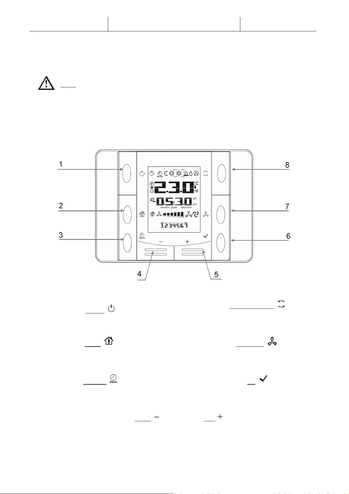
3.2 Button Overview
The Room Unit interface has the following operating elements:
(1) On/Off
• Unit state changeover
(2) Home
• Enabling/Disabling of Occupancy mode &
main page return button
(3) Program
• Set date/time and time scheduler
(4) Minus (5) Plus
• Adjust temperature setpoint and menu navigation
(8) Cool/Heat Mode
• Switch between Cooling (Summer) and
Heating (Winter) mode
(7) Fan Speed
• Change the supply and return fan speed
control mode
(6) OK
• Confirm button and alarm management
4
Page 5

Display
Meaning
Modular-Light AHU
3.3 Display Overview
The table below explains all the symbols available on the display:
Room temperature value
Time
Day of the week
1= Monday
2= Tuesday
etc…
Fan speed visualization
User Manual
Fan speed control mode set to Auto
On/Off state of the unit.
This icon is:
1. On - when the unit is in On, Ventilation or Economy state.
2. Off - when the unit is Off.
3. Blinking - when the unit is in Test mode or in off state by Panel
Switch.
Unit control mode set to Auto.
The actual unit state and relative icons (On, Off, Ventilation or Economy)
are based on Time Scheduler settings.
Economy mode active
Ventilation mode active
Occupancy mode active
Dehumidification control active
Heating mode (Winter)
Cooling mode (Summer)
Unit Cool/Heat (Summer/Winter) mode changeover set to Auto
Unit in alarm (see Alarm section for further info)
5
Page 6

U
nit State
changeover
Two examples of main screen display:
Economy mode, cooling Ventilation mode, heating
3.4 Operating instructions
This button allows the user to change unit actual operating state. To change unit state follow these
steps:
Modular-Light AHU
User Manual
1. Press the On-Off button
2. Navigate through the different available states by pressing + or – buttons:
- Auto = unit follows time scheduler settings
- On = unit on with nominal setpoints
- Off = unit off
- Ventilation = only fan active, no heat/cool control
- Economy = unit on with economy setpoints
3. Confirm the change of state by pressing for at least 1 second the OK button
4. To return to the main screen page without taking any action, either press the Home button
or wait for 5 seconds
Occupancy mode
Occupancy is a function that allows to run the unit for fixed period even if it is “Off” via time
scheduler. This time period can be configured during unit commissioning.
To activate/deactivate the Occupancy function follow these steps:
1. Press the Home button
2. Navigate through the different available states by pressing + or – buttons (Off, On)
3. Confirm the change of state by pressing for at least 1 second the OK button
4. To return to the main screen page without taking any action, either press the Home button
again or wait for 5 seconds
6
Page 7

Date and Time settings
Modular-Light AHU
User Manual
To change the date and time displayed on the main screen follow these steps:
1. Press PROG button . Time will start blinking, then set the hour with the + and -
2. By pressing the OK button the hour is saved and minutes blink, then set minutes with + and
-
3. By pressing the OK button minutes are saved and the entire time blinks, then set the time
display format (12/24 hour) with + or –
4. By pressing the OK button the display format is saved and the year blinks, then set the
desired year with + and -
5. By pressing the OK button the year is saved and the display shows month/day, with month
blinking, then set the month with the + and -
7
Page 8

Modular-Light AHU
User Manual
6. By pressing the OK button month is saved and day blinks, then set the day with the + and -
7. By pressing the OK button month and day are saved, the display returns to the time
8. By Pressing PROG button the display returns to normal view
The display automatically returns to normal view when the PROG button is not pressed within one
minute.
Time Scheduler settings
The scheduler is working with 7 weekdays and 6 switches can be set up for each day. By setting up
the switch, the user can set a time point and select one operation in Auto mode.
To set the time scheduler follow these steps:
1. Hold PROG button to enter time scheduler setting. In time scheduler, button is used to
cancel, while OK button to confirm.
2. Pressing button + or -, the number of corresponding weekday will blink on screen. Holding
button + or -, cursor will keep moving on the weekdays in a cyclic way.
3. When cursor moves onto one weekday, pressing button will select this number or deselect
it. When one weekday is selected, the day will be displayed on screen constantly. More than one
weekday can be selected.
8
Page 9

Modular-Light AHU
User Manual
4. When cursor reaches the end of the week (i.e. 7) by pressing button + or the beginning of the
week (i.e. 1) by pressing button -, all the selected weekdays will be displayed on screen with their
indicators blinking. Pressing once will confirm them all.
5. After the confirmation of weekdays, pressing + or - again will jump to the following view. The
first line is number of operation; the second line is time setting, the invalid time “--:--“ is used to
add a switch.
6. Press button + and - to set up time point and select an operation, and press to confirm the
input. The operation codes are the following:
- 0 = Off
- 1 = On
- 2 = Ventilation
- 3 = Economy
In any parts of time area, press when the cursor is located on “--” without a number is
selected, the switch will be deleted, and it will go back to viewing switch.
9
Page 10

Modular-Light AHU
User Manual
7. In scheduler setting, pressing button will go back to the previous page. User can press this
button to exit the setting step by step. The time scheduler setting page is automatically closed if no
operation was performed for 1 minute, and all changes made after pressing button will not be
saved.
Temperature setpoint control
The buttons + or - are used to define Heat/Cool temperature setpoint.
By single pressing + or - buttons on main screen, the actual setpoint is being displayed. Every other
press increases/decreases the temperature setpoint of 0.1 °C.
A long press of the + or - buttons display the actual temperature offset determined with the room
unit from the main setpoint.
Fan speed control
This button allows the user to change actual control mode for Supply and Return fan.
To change fan speed control mode follow these steps:
1. Press Ventilation button
2. Navigate through the different available states by pressing + or – buttons:
- Auto = unit follows nominal fan setpoints
- Speed 1* = unit follows fixed speed 1 value
- Speed 2* = unit follows fixed speed 2 value
- Speed 3* = unit follows fixed speed 3 value
3. Confirm the change of state by pressing for at least 1 second the OK button
4. To return to the main screen page either press the Home button or wait for 5 seconds
*NOTE! if unit is in “Pressure Control” mode, only AUTO fan control mode will be available.
Cool/Heat changeover
This button allows the user to change Unit Cool/Heat state (or Summer/Winter state).
To change the Cool/Heat state follow these steps:
1. Press the Cool/Heat changeover button
10
Page 11

Modular-Light AHU
User Manual
2. Navigate through the different available states by pressing + or – buttons (Cool, Heat)
3. Confirm the change of state by pressing for at least 1 second the OK button
4. To return to the main screen page without taking any action, either press the Home button
or wait for 5 seconds
NOTE! When icon appears on the Room Unit main screen, the Summer/Winter change source
on the main controller has been set on Auto during commissioning phase and Summer/Winter
cannot be changed via Room Unit.
3.5 Alarms
When the alarm icon appears on the interface, an alarm has occurred on the unit. In order to check unit
status and actual alarm code, the user must go to the alarm code screen page.
A long press of the OK button will get the user on the alarms code screen page. Another long press of
the OK button will attempt to reset the alarm, if possible. Please contact your local Daikin service
representative if you need additional support.
The alarm code consists of four slots. The first two represents the alarm type, with the following meanings:
- FL -> Fault alarm (unit stops)
- OP -> Operation alarm (unit keeps running)
The other part of the string represents the numeric code of the alarm. For a complete list of alarm code,
check the following table:
Alarm Code Alarm String Description
Supply or Return filter dirty:
OP01
OP02
FL04
Filter alarm
Air quality (CO2)
sensor alarm
Supply fan alarm
differential pressure switch of the filters detected an high pressure
difference pressure between input and output of the filter. Check filters
status.
CO2 percentage too high:
measured value of CO2 is out the allowable range or error condition on
the air quality sensor (not connected or broken).
Error condition on Supply fan:
Supply fan has detected a failure. Check fan status.
FL05
FL06
FL07
Return fan alarm
Heating/Cooling
Coils alarm
Heat Recovery freeze
alarm
Error condition on Return fan:
Return fan has detected a failure. Check fan status.
Error condition on Heating/Cooling coils:
one or more heating/cooling coils have detected a failure. Check their
status.
Heat Recovery freeze alarm active:
unit heat recovery freeze protection has intervened to prevent damage
to the device and has turned off the unit. After a time period, the unit
will automatically reset the alarm and start again.
11
Page 12

Modular-Light AHU
Alarm Code Alarm String Description
Fire alarm active:
FL09
Fire alarm
fire detector device detected fire presence. Unit enters fire mode.
User Manual
Supply temperature sensor error:
measured temperature out of the allowable range or error condition on
the temperature sensor (not connected or broken).
Return temperature sensor error:
measured temperature out of the allowable range or error condition on
the temperature sensor (not connected or broken).
Outside temperature sensor error:
measured temperature out of the allowable range or error condition on
the temperature sensor (not connected or broken).
Exhaust temperature sensor error:
measured temperature out of the allowable range or error condition on
the temperature sensor (not connected or broken).
Supply fan pressure sensor error:
measured pressure out of the allowable range or error condition on the
pressure sensor (not connected or broken).
Return fan pressure sensor error:
measured pressure out of the allowable range or error condition on the
pressure sensor (not connected or broken).
FL11
FL12
FL13
FL14
FL15
FL16
Supply temperature
sensor fault
Return temperature
sensor fault
Outside temperature
sensor fault
Exhaust temperature
sensor fault
Supply fan sensor
fault
Return fan sensor
fault
The present publication is drawn up by of information only and does not constitute an offer binding upon Daikin Applied Europe S.p.A..
Daikin Applied Europe S.p.A. has compiled the content of this publication to the best of its knowledge. No express or implied warranty is
given for the completeness, accuracy, reliability or fitness for particular purpose of its content, and the products and services presented
therein. Specification are subject to change without prior notice. Refer to the data communicated at the time of the order. Daikin Applied
Europe S.p.A. explicitly rejects any liability for any direct or indirect damage, in the broadest sense, arising from or related to the use
and/or interpretation of this publication. All content is copyrighted by Daikin Applied Europe S.p.A..
DAIKIN APPLIED EUROPE S.p.A.
Via Piani di Santa Maria, 72 - 00072 Ariccia (Roma) - Italia
Tel: (+39) 06 93 73 11 - Fax: (+39) 06 93 74 014
http://www.daikinapplied.eu
12
 Loading...