

Page 1

Installation, use
and maintenance manual
Modular Light
Modular L
Translation of the original instructions
Page 2

Modular Light heat recovery units guarantee high quality indoor air at low energy
costs. The range consists of six sizes, customisable by adding external modules.
Armed with an extremely flexible development, Daikin air handling units are able to
satisfy all types of technical requirements.
Daikin systems guarantee respect for the environment since they are based on high
levels of energy efficiency. Reduced ecological impact and low energy consumption
make Daikin recovery units ideal for any type of market.
Page 3

Contents
Assembly instructions
Important warnings 4
Purpose of the manual 4
Intended use of the machine 4
Safety regulations 5
Residual risks 8
Safety devices 9
Machine characteristics 10
Environmental conditions 10
Environmental contamination 10
Noise 10
Ceiling and air duct specifications 11
Technical data 12
Attachments 12
Summary of machine operation 14
Receipt of the cartons 15
Transport 16
Unpacking and verification of integrity
After unpacking 17
Reading the serial number plate 18
Storage waiting for installation 19
17
Installation 20
Installation procedure 20
Maintenance 28
Safety precautions for maintenance 28
Ordinary maintenance 29
Extraordinary maintenance 33
Diagnostics 36
Troubleshooting table 37
Repair log 38
Page 4
1
Important warnings
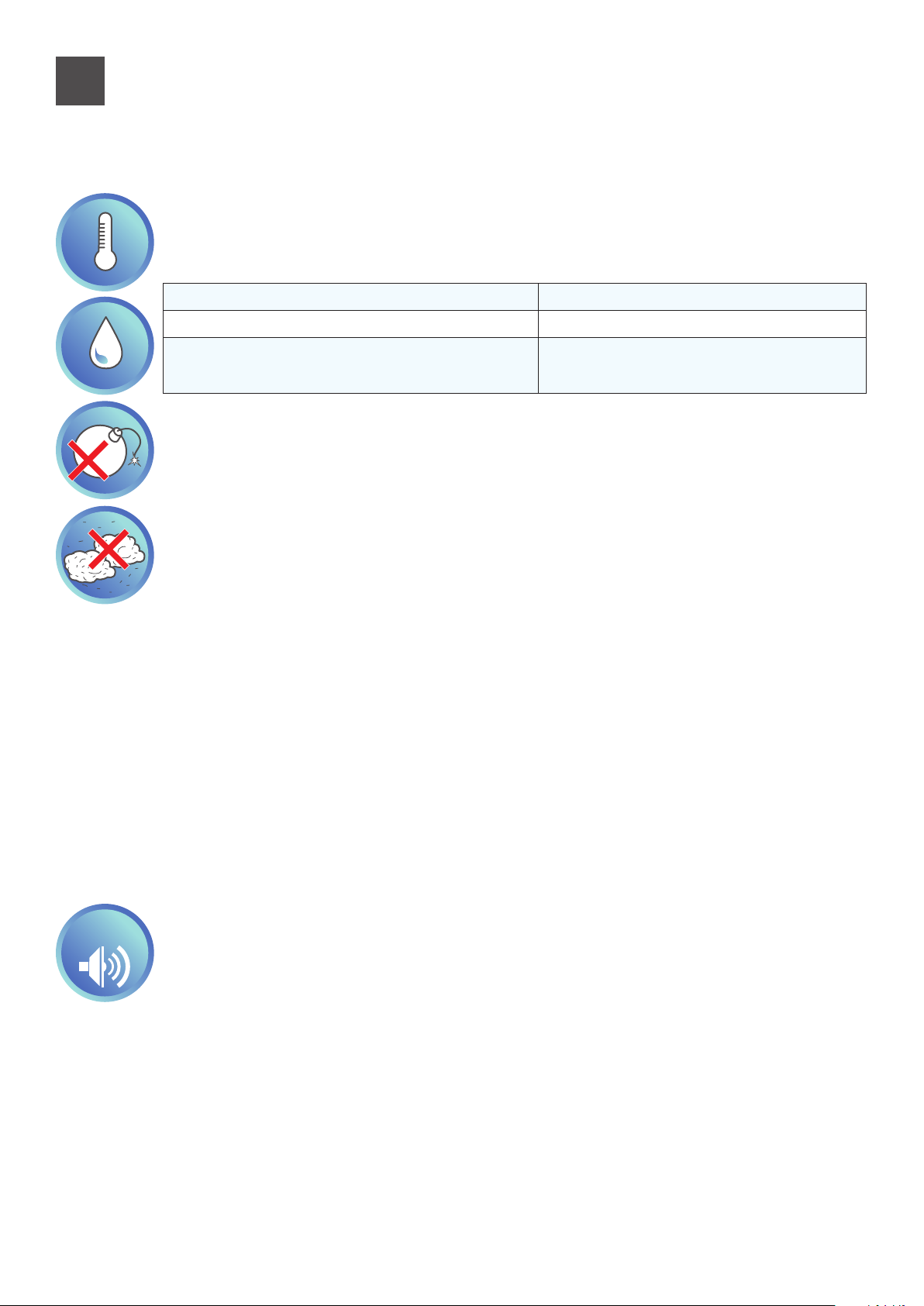
The pictogram shows a situation of immediate danger or a dangerous situation that might cause injuries or death.
The pictogram shows that it is necessary to adopt suitable behaviour in order to avoid jeopardising staff safety and
cause damages to the equipment.
The pictogram shows particularly important technical information that should be taken into consideration by the
people installing or using the equipment.
Purpose of the manual
The purpose of this manual is to guide the installer and qualified operator in the installation,
maintenance and proper and safe use of the equipment. For this reason, it is mandatory for all
personnel involved in installation, maintenance and supervision of the machine to read this
manual.
Contact the manufacturer if any points are unclear or difficult to understand.
This manual contains information regarding:
- Technical specifications of the machine.
- Instructions for transport, handling, installation and assembly.
- Use.
- Information for instructing personnel authorised for its use.
- Maintenance activities.
All information refers in general to any unit of the Modular Light ranges. All the units are shipped
together with a technical schematic indicating the specific weight and size of the machine received.
It must be considered an integral part of this manual and therefore it must be kept with the utmost
care in all its parts.
If the manual or schematic is lost, it is important to request a copy from the manufacturer, specifying
the unit's serial number and date of purchase that can be found on the invoice.
In the case of divergent information between this manual and the schematic, the schematic will
prevail.
Intended use of the machine
This appliance has the function of treating the air intended to condition civil and industrial environments. Any other use is not in accordance with the intended use and therefore dangerous.
These ranges of units are designed for use in NON-explosive environments. For installation in
potentially explosive environments, the manufacturer can design and manufacture suitable machines
(anti-explosion) that will be identified by the mark .
If the machine is used in critical situations, by type of system or environmental context, the customer
must identify and adopt the technical and operational measures to avoid damage of any kind.
4
Page 5
Safety regulations
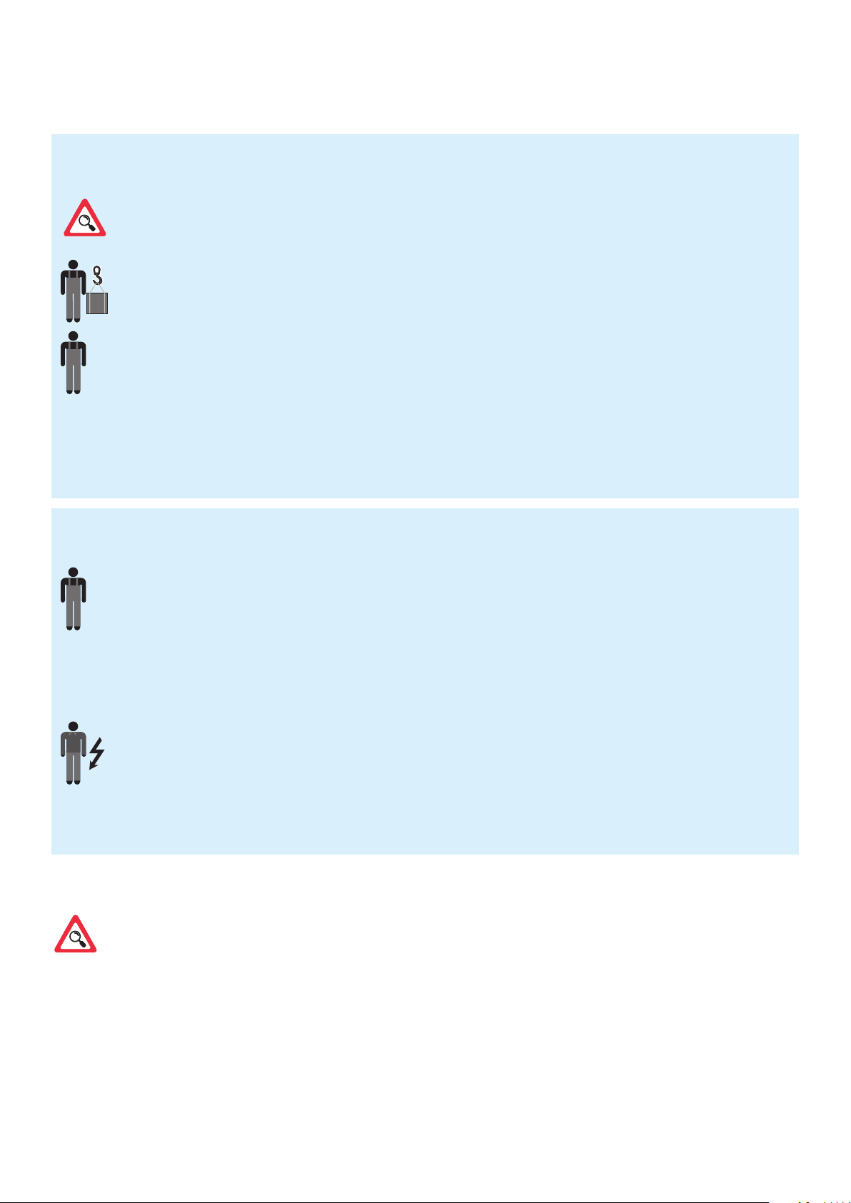
Skills required for the installation of the machine
Installers must perform operations according to their professional qualifications: all activities not within one's expertise
(i.e. electrical connections) must be carried out by specialised and qualified staff so as not to endanger one's safety and
the safety of the other operators interacting with the machine.
Transport and equipment handling operator: authorised person with recognised expertise in using transport
and lifting equipment.
Technical installer: expert technician, sent or authorized by the manufacturer or its representative, with adequate
skills and training to install the machine.
Assistant: technician subject to care obligations while lifting and assembling the equipment. He must be suitably
trained and informed about the operations to perform and the safety plans of the site/installation location.
In this manual, the technician competent to carry out each operation is specified.
Skills required for the use and maintenance of the machine
Generic operator: AUTHORISED to run the machine using commands placed on the keypad of the electrical control
panel. Performs only machine control operations, power on/off.
Maintenance mechanic (qualified): AUTHORISED to carry out maintenance, adjustments, replacement and repair
of mechanical parts. It must be a person competent in mechanical systems, therefore able to perform mechanical
maintenance in a satisfactory and safe manner, must possess theoretical preparation and manual experience. NOT
AUTHORISED to work on electrical systems.
Manufacturer's technician (qualified): AUTHORISED to perform complicated operations in every situation.
Operates in accordance with the user.
Maintenance electrician (qualified): AUTHORISED to perform service of an electric nature, adjustments,
maintenance and electrical repairs. AUTHORISED to operate in the presence of an active electrical connection inside
the control panels and junction boxes. It must be a person competent in electronics and electrical engineering,
therefore able to work on electrical systems satisfactorily and safely, must possess theoretical knowledge and proven
experience. NOT AUTHORISED to work on mechanical systems.
Installers, users and maintenance staff for the machine must also:
- Be responsible and experienced adults without physical impairments, in perfect psychological and physical condition.
- Master the machine's operating cycle, therefore participate in theoretical/practical training alongside an expert machine operator,
or alongside a technician of the manufacturer.
In this manual, the technician competent to carry out each operation is specified.
5
Page 6
Read this manual carefully before machine installation and maintenance and keep it for any
further future consultation by the various operators. Do not remove, tear out or rewrite any part
of this manual.
All installation, assembly, electrical connections to the mains and ordinary/extraordinary
maintenance must be performed only by qualied personnel authorised by the Retailer
or Manufacturer after turning off the unit electrically and using personal protective
equipment (i.e., gloves, protective goggles, etc.), in compliance with the regulations in force in
the country the equipment is to be used in and the laws regarding the systems and safety in
the workplace.
Installation, use or maintenance other than those specified in the manual may cause damage,
injury or death, invalidate the warranty and relieve the Manufacturer of any liability.
Use protective clothing and suitable equipment while handling or installing the equipment, in
order to prevent accidents and safeguard your own and other people's safety. Individuals not
assigned to installation or maintenance are NOT allowed to stand or pass through the work area
while the machine is assembled.
Disconnect the equipment from the mains before installing or maintaining it.
Before installing the equipment, check that the systems comply with the legal provisions in
force in the country of use and meet the specifications on the serial number plate.
It is the responsibility of the user/installer to check the static and dynamic stability relative to
the installation and to arrange environments so that people who are not competent or
authorised DO NOT have access to the machine or to its commands.
It is the responsibility of the user/installer to make sure that weather conditions do not affect
the safety of persons and property during installation, use and maintenance.
Make sure the air intake is not located near any exhausts, flue-gases or other contaminating
elements.
Do not install the equipment in places exposed to strong winds, salt air, open flames or
temperatures exceeding 40°C (104°F).
After installation is complete, instruct the user on the correct use of the machine.
If the equipment does not work or functional or structural alterations are noted, disconnect
it from the mains and contact a service centre authorised by the Manufacturer or Retailer,
without attempting to repair it on your own. For any replacements request the use of original
spare parts.
Unauthorised actions, tampering or modifications that do not follow the information provided
in this manual can cause damage, injuries or fatal accidents and void the warranty.
6
Page 7

The serial number plate on the unit provides important technical information, essential in case
of machine maintenance or repairs. We recommend that you do not remove, damage or modify
it.
In order to ensure correct and safe conditions of use, it is recommended to have the unit
maintained and checked at least annually by a service centre authorised by the manufacturer or
dealer.
Failure to follow these instructions may cause damage and injuries, even fatal, voids the
warranty and relieves the Manufacturer of any liability.
7
Page 8
Residual risks
Despite having implemented and adopted all the safety measures indicated by applicable regulations,
some residual risks remain. In particular, in some operations of replacement, adjustment and tooling maximum attention is always required in order to work in the best possible conditions.
List of operations with residual risks
Risks for qualified personnel (electrician and mechanic)
- Handling - during unloading and handling it is necessary to pay attention to all the steps listed in this manual regarding the points
of reference
- Installation - during installation it is necessary to pay attention to all the steps listed in this manual regarding the points of reference
The installer must ensure the static and dynamic stability of the machine's site of installation.
- Maintenance - during maintenance it is necessary to pay attention to all the steps listed in this manual, and in particular to high
temperatures that may be present in the heat transfer fluid lines to/from the unit.
- Cleaning - the machine must be cleaned only when it is switched off, by turning off the switch installed by the electrician and
the switch located on the unit itself. The key for interrupting the power supply must be kept by the operator until the end of the
cleaning operations. Internal cleaning of the machine must be carried out using the protections required by current regulations.
While the inside of the machine does not contain particular hazards, it is necessary to pay the utmost attention so that accidents
do not occur during cleaning. The heat exchange coils that have a potentially sharp finned pack must be cleaned using protective
glasses and gloves suitable for handling metals.
During adjustment, maintenance and cleaning there are residual risks of variable entity. Being operations
that must be performed with guards disabled, it is necessary to pay particular attention in order to avoid
damage to persons and things.
Always pay close attention when performing the operations specified above.
Remember that these operations must always be performed by authorised personnel.
All work must be completed in accordance with the legal provisions relating to work safety.
Remember that the unit in question is an integral part of a larger system that includes other components,
depending on the final characteristics of realisation and the mode of use. Therefore in the end it is
the responsibility of the user and assembler to assess the residual risks and their respective preventive
measures.
For more information about the possible risks, please refer to the RAD (Risk Assessment
Document) available from the manufacturer.
8
Page 9

Safety devices
The machine is equipped with safety devices to prevent risks of damage to persons and for
proper operation. Always pay attention to the symbols and safety devices on the machine. It
should only operate with the safety devices engaged and with fixed or movable guards
installed correctly and in the proper position.
If during installation, use or maintenance the safety devices have been temporarily removed
or disabled, the machine can be operated exclusively by the qualified technician who made
this change. It is mandatory to prevent other people's access to the machine. When finished,
restore the devices to their proper status as soon as possible.
9
Page 10
2
Machine characteristics
Environmental conditions
Modular Light heat recovery units are designed for use in indoor environments, installed on
the ceiling. The unit cannot operate in environments containing explosive material and with
a high concentration of dust.
Outside air temperature
Operating environment temperature
Temperature of the environment with the ma-
chine off (e.g., storage, transport, etc.)
Thanks to its modularity, each machine is able to adapt to different needs in terms of air flow
and thermodynamic treatments.
The optimised choice of every detail, the search for maximum efficiency in each
component, the adoption of specific materials and constructive solutions transform
environment friendliness and energy savings into valid and advanced technological
solutions.
-25°C to +45°C
+5°C to +45°C
-40°C to +60°C
Environmental contamination
Depending on the installation operating environment, specific regulations must be followed and all the
necessary precautions must be taken to avoid environmental issues (a system that operates in a hospital
or chemical environment can have problems different from those in other sectors, even from the point of
view of disposal of consumable parts, filters, etc.).
It is mandatory for the buyer to inform and train workers regarding proper procedures.
Noise
The machines have been designed and manufactured in such a way as to produce sound
> 80 dB(A)
during the machine's actual use.
10
emissions below the threshold of 80 dB(A). It should be noted that every environment has
its own acoustic characteristics that can greatly affect the noise perceived during operation,
therefore it is necessary to consider the noise data provided as a point of reference, while it
is up to the buyer to perform specific sound level measurements at the installation site and
Page 11
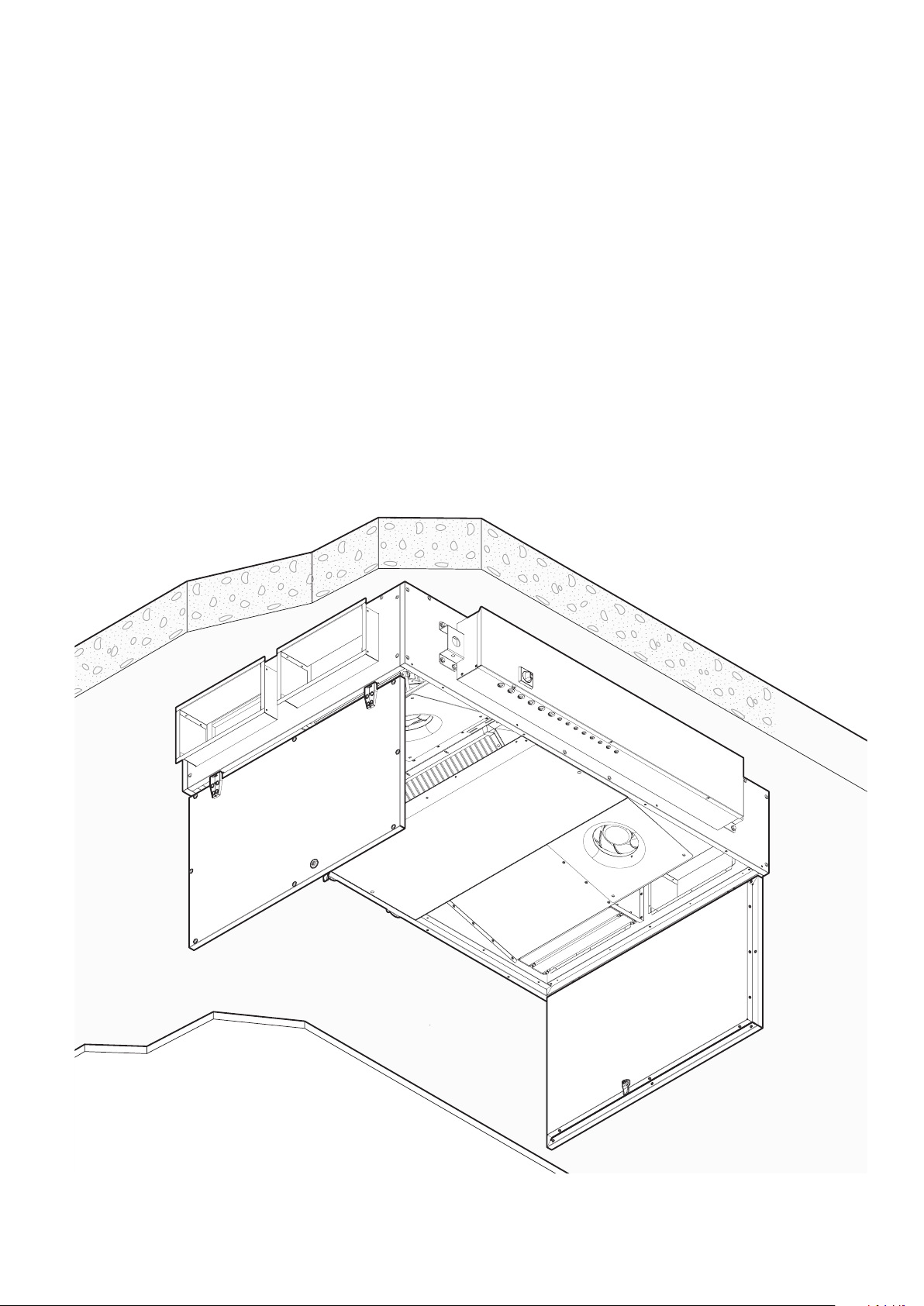
Ceiling and air duct specifications
The ceiling where you plan to install the machine must be:
- Perfectly flat and without roughness.
- Vibration resistant.
- Able to support the weight of the equipment considering an appropriate safety margin (see table of technical data on page
12).
The equipment installed on the ceiling can adapt easily to the presence of a false ceiling.
In fact, without sufficient space for up-and-over door opening, the inspection door can be transformed
into a panel able to slide on accessory guides (optional)
If provided, the air ducts must be connected directly to the machine, taking care to insert a suitable
anti-vibration system between the machine itself and the duct. When assembly is completed they must
not be taut, in order to avoid damage and transmission of vibrations.
To ensure the seal of the connections and the integrity of the machine, it is essential that the air ducts be
supported by special brackets that do not weigh directly on the machine.
11
Page 12
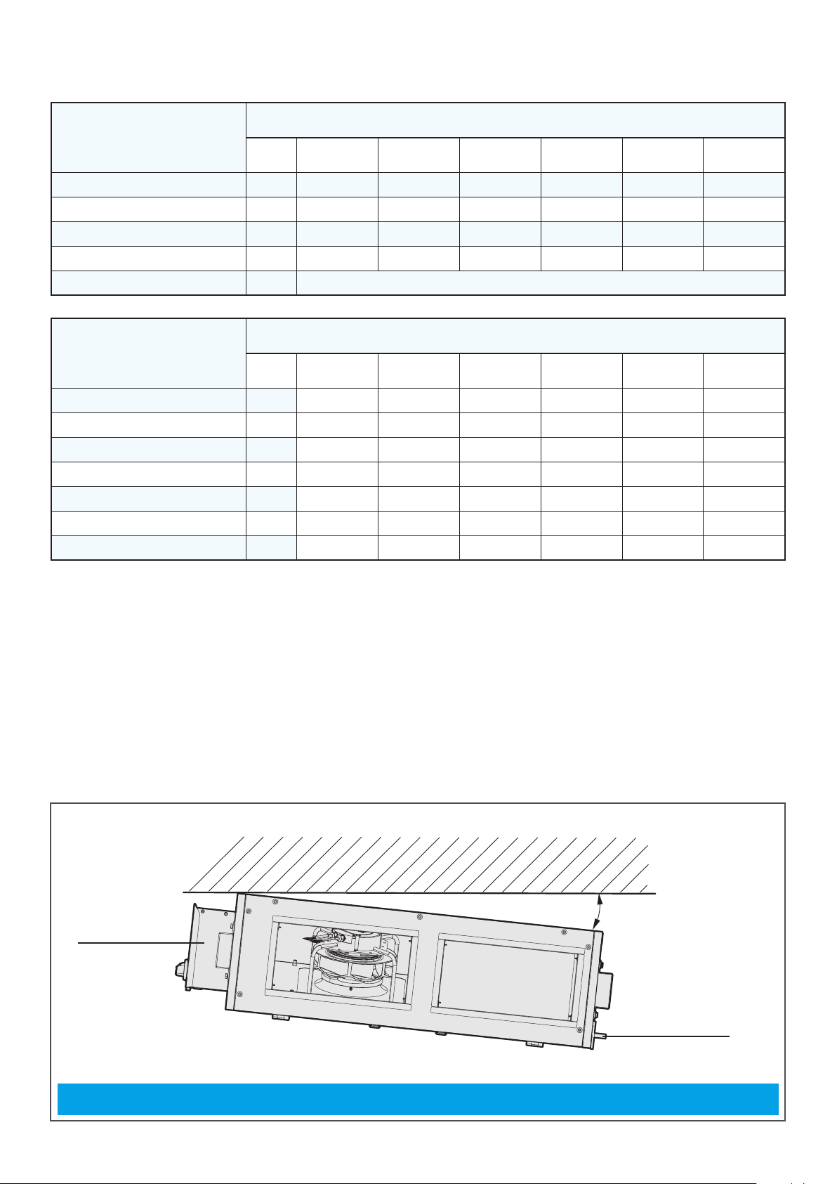
Technical data
TECHNICAL DATA TABLE
SIZE
2 3 4 5 6 7
Nominal air flow rate
m3/h
Heat efficiency %
FLA
FLI
W
Electrical connection
WEIGHT TABLE
Gross weight with packaging
Device weight
Door weight
Filter weight
Fan weight
Recuperator weight
Tank panel weight
kg
kg
kg
kg
kg
kg
kg
300 600 1200 1500 2500 3000
89 89 89 89 90 89
A
2.80 4.50 4.50 4.70 8.90 9.30
371 1033 1033 1033 2033 2033
200-277 V, 1 ph
SIZE
2 3 4 5 6 7
135 190 285 295 370
125 180 270 280 355
2x10,0 2x12,0 2x18,0 2x18,0 2x22,0
2x0,2 2x0,3 2x0,5 2x0,5 2x0,5
2x2,5 2x8,5 2x8,5 2x9,0 4x8,5 4x9,0
1x9,0 1x14,0 2x15,0 2x15,0 2x24,0 2x24,0
1x13,0 1x16,0 1x24,0 1x24,0 1x29,0 1x29,0
375
360
2x22,0
2x0,5
Preheating external coil
Kindly make sure that the frontal velocity through the preheating element is maintained above 1.5 m/s
for safety reasons.
Electric
panel
Electric
panel
The machine must be tilted by approximately 2% of the width (B) (lifting it towards the electric panel)
1
2%
Condensation
discharge
12
Page 13

B
A
C
F
TECHNICAL DATA
TABLE
D
H
ø14 mm
ø14 mm
ø14 mm
E
G
160 mm
80 mm
SIZE
2 3 4 5 6 7
Length (A) mm
Width (B) mm
Height (C) mm
Hole distance (D) mm
Hole distance (E) mm
F (up-and-over doors)
mm 630 670 675
1660 1800 2000 2000 2000 2000
920 1100 1600 1600 2000 2000
280 350 415 415 500 500
1380
976 1156 1656 2056
F (sliding doors) mm 70
G mm 500
H mm 300
13
Page 14

Summary of machine operation
2
5
4
A
3
6
C
D
1
B
1
air flow in a machine with orientation to the right
2
Filter and pre-filter
1
Exchanger by-pass
2
Heat exchanger
3
Delivery motor-driven fan group
4
Delivery motor-driven fan group
5
Intake motor-driven fan group
6
Pos. Component name Construction material
Supply air
A
Internal air
B
Exhaust air
C
Air from outside
B
1 Filter galvanised steel frame, fibreglass filter unit
2 Bypass aluzinc
3 Heat exchanger aluminium
4 Fan motor assembly size 2: composite board frame and impeller
size 3,4,5,6,7: steel frame, composite board impeller
5 Brackets galvanised steel
14
Page 15

3
The means and method of transport must be chosen by the transport operator according to the type, weight and size of the
machine. If necessary, draw up a "safety plan" to guarantee the safety of the people directly involved.
Receipt of the cartons
Handle the equipment following the Manufacturer's instructions on the packaging and in this manual.
Always use personal protective equipment.
Upon receipt of the machine check the integrity of the packaging
and the amount of parcels sent:
A) There is visible damage/one or more cartons is missing: do not
install, but promptly notify the Manufacturer and the carrier that
made the delivery.
Alternatively you can accept the shipment "subject to
verification": this will make it possible to open the cartons
and check if the internal components are indeed damaged.
In the latter case, as noted previously, promptly notify the
Manufacturer and the carrier that made the delivery.
Before opening the cartons, it is recommended to take good
quality pictures to document the damage.
B) There is NO visible damage: move the machine to the site of
installation.
15
Page 16

4
sudden movements.
Transport
Packages can be handled with a pallet truck of suitable capacity or with a forklift. The choice of the
most suitable means and method lies with the operator.
The operating area must be perfectly free from objects or people not involved in the transport.
If transport is done using a pallet truck make sure it is suitable for the weight and size of the
machine. Insert the forks into the points provided for handling (usually in a central position) so as
to keep the centre of gravity of the load in balance. Move the equipment carefully, avoiding
OK!
OK!
16
Page 17

A
5
Unpacking and verification of integrity
We recommend the equipment be unpacked after moving it to its installation location and only when
it is to be installed. This operation must be performed using personal protection equipment (i.e., gloves,
safety shoes, etc.).
Do not leave the packing unattended: it is potentially harmful to children and animals
(suffocation hazard).
Some packing materials must be kept for future use (wooden crates, pallets, etc.), while those that
cannot be reused (i.e., polystyrene, strapping, etc.) must be disposed of in compliance with the
regulations in force in the country of installation: this will protect the environment!
After unpacking
After unpacking, check the received contents:
- Installation and maintenance manual (IOM)
- Wiring diagram
- Declaration of conformity
Check therefore that you have received all the components and that they are undamaged
In case of damaged or missing parts.
- Do not move, install or repair damaged components and the machine in general.
- Take quality photos to document the damage.
- Find the serial number plate on the machine and note the machine's serial number.
- Immediately notify the carrier that delivered the machine.
- Promptly contact the Manufacturer (keep on hand the serial number of your machine).
Please note that complaints or claims of damage reported after 10 days of receipt of the machine
cannot be accepted.
A: Manufacturer’s name and data
Codifica
HU
Product number
Matricola
Serial number
Mandata
Supply Fan
MESSA IN FUNZIONE
All’avviamento consultare il manuale
operavo e controllare:
1) senso di rotazione del venlatore
2) l’assorbimento del motore, il quale non
deve superare il valore di targa sopraindicato
D
ALB07LBMNADBT00 A83665
I
18C0144
PORTATA ARIA /AIR FLOW
3000
F
Corrente / Current
Tensione / Voltage 230V/1Ph/50-60Hz
DAIKIN APPLIED EUROPE S.p.A
Via Piani di Santa Maria, 72 00040 Ariccia - (ROMA) IT
A
Data
Date
m3/h
H
START UP
Before the start up read carefully the operang
instrucon manual and check
1) fan rotaon direcon
2) the current input must not exceed the value
menoned on the above tag
MADE IN ITALY
POS
Code
E
Peso
4/2018 373
Weight
B
Ripresa
Return Fan
G
9.3 A
C
m3/h
B: CE markings
C: Machine weight
D: Code and POS
E: Date of manufacture
F: Supply airow rate
G: Delivery airow rate
H: Electrical specications (frequency, number of
phases, absorption in plate conditions)
I: Machine serial number
MANUFACTURER INFORMATION:
DAIKIN APPLIED EUROPE S.P.A.
Via Piani di Santa Maria, 72 - 00040 Ariccia (Roma) - Italy
Tel: (+39) 06 93 73 11 - Fax: (+39) 06 93 74 014
http://www.daikinapplied.eu
17
Page 18

Product nomenclature
A L B 07 L B M N A D B T 0 0
A AHU
L Modular Light
B Main module
02 Size 02
03 Size 03
......
07 Size 07
R right installation
L left installation
B release
M advanced controller solution
S smart controller solution
E internal electric post heating coil
W internal water post heating coil
N no internal post heating coil
A raluminium recuperator
M membrane recuperator
A Supply filter G4
B Supply filter M5
D Supply filter F7
E Supply filter F9
A Delivery filter G4
B Delivery filter M5
D Delivery filter F7
E Delivery filter F9
T Double panel thickness 50mm, mineral wool
insulation, pre-painted exterior and Aluzinc interior
0.... Production site
0.... Version
Modular Light will be produced according to customer needs.
However, we still designed a standard version indicated by only 7 digits ALB01R(L)A and that
uniquely identifies a right/left machine, aluminium counter-current exchanger, double 50mm
panel, with Microtech controller, no internal post heating coil, F7 at supply, M5 at delivery, version 01.
18
Page 19

Storage waiting for installation
Waiting for the installation, the components of the machine and the relative documents must be stored
in an area that:
- Is dedicated exclusively to the storage of the components.
- Is covered and protected from the weather (preferably prepare a closed area), with adequate temperature and humidity.
- Is accessible only to operators tasked with the assembly.
- Can support the weight of the equipment (check the load rating) and has a stable floor.
- Is free from other components, especially if they are potentially explosive/incendiary/toxic.
If you cannot proceed with the installation straight away, check periodically that the above-mentioned conditions of the storage area are maintained and cover the machine with a canvas.
While waiting for the finale installation, always provide an insulating base (e.g., wood blocks)
between the floor and the machine itself.
Correct storage awaiting installation
3
Any movement carried out after unpacking must be done with the doors closed. Do not move
the units by pulling on the doors, if present, the uprights or other protruding parts that are not
an integral part of the structure.
5÷35°C
Do not step on the units!
19
Page 20

2A
6
Installation
All installation, assembly, electrical connections to the mains and extraordinary maintenance
must be performed only by qualied personnel authorised by the Retailer or
Manufacturer, in compliance with the regulations in force in the country the equipment is to
be used and the standards on the systems and safety in the workplace.
During installation, the area must be free from people
and objects not used for the assembly.
Before starting, make sure you have all the necessary
equipment.
Use only equipment that is in good condition and
undamaged.
Installation procedure
Before installation, read the safety instructions on the first pages of this manual. Contact the Manufacturer
if any points are unclear or not perfectly understandable. A check mark next to each step will help to
confirm complete and proper installation.
Step 1: Mark the drilling points .............................................................................................................................. page 21
Step 2: Make the connections ................................................................................................................................ page 23
Step 3: Perform a trial run .......................................................................................................................................... page 26
Step 4: Safety signs .........................................................................................................................................................page 27
After installation store this manual and the assembly sheet that accompanied the machine in a place that
is dry and clean. This way it will be accessible to operators in the future who need to consult it.
Do not remove, tear out or write on any part of this manual besides the space set aside for notes:
Step 0: Lift the unit to the ceiling
Lift the unit up to the ceiling.
To facilitate the operations of lifting and to ensure the safety of the installers, we recommend the
use of extensible pantograph lifts of the appropriate type and dimensions for the weight and size
of the unit to be installed.
During lifting protective apparel must be worn to prevent injury, and individuals not assigned to installation
or maintenance are NOT allowed to stand or pass through the work area.
20
Page 21

Step 1: Mark the drilling points
Make sure that the ceiling where you plan to install the machine is:
- Vibration resistant.
- Able to support the weight of the equipment (see table of technical data on page 12).
The installation site must also include (fig. 4):
• An electrical system compliant with current regulations and with specifications that meet the needs
of the machine;
• a coolant gas connection (in the case of connection to coils supplied by gas).
• A drain pipe with drain siphon connected to the sewerage system.
• An aeraulic system (ducts for the air to be conveyed to the environments).
Drill ø14 mm holes at the machine anchor holes
Insert the appropriate anchors, lift the machine and fasten it using only the brackets and screws supplied.
Electric
panel
The machine must be tilted by approximately 2% of the width (B) (lifting it towards the electric panel)
4
A
(see “technical specifications” table on page 13).
Electric
panel
2%
Condensation
discharge
Ceiling drilling
5
A
21
Page 22

x4
Install a
shockproof
rubber hose.
Ceiling drilling
6
While lifting and fastening the unit it is
mandatory to use protective clothing and
suitable equipment, in order to prevent
accidents and safeguard your own and other people's
safety.
The fastening equipment should be dimensioned
according to unit weight.
Individuals not assigned to the installation are NOT
allowed to stand or pass through the work area
during assembly.
To facilitate the operations of lifting and to
ensure the safety of the installers, we
recommend the use of extensible
pantograph lifts of the appropriate type and
dimensions for the weight and size of the unit to be
installed.
22
Page 23

Step 2: Make the connections
To operate the machine requires:
- An electrical connection.
- Drain.
- A connection to the aeraulic circuit (air ducts).
Electrical connections
For the power supply it is necessary to connect the machine to an electrical panel in compliance with
current regulations.
Always refer to the wiring diagram that is specic to the machine that you bought (it was
shipped with the unit). If it is not on the machine or has been lost, contact the salesperson of
reference who will send a copy (specify the machine's serial number).
Before connecting the machine make sure that:
• The voltage and frequency of the power supply correspond to the parameters of the machine.
• The electrical system being connected has sufficient capacity to supply the nominal electric power of
the machine to be installed and meets current regulations.
The electrical connection must be:
• Performed by qualified personnel after cutting off the facility's power supply.
• Performed in a fixed and permanent manner, without intermediate splices, in accordance with the
regulations of the country of installation.
• The power supply is sufficient for the machine (see technical specifications).
• Includes a functioning grounded plug. For multiple units it is necessary to combine them all with metal ties.
• Preferably situated in a dedicated room, locked and protected from atmospheric agents. If there is also
a key switch, the key must be removed when cutting the power supply and returned to its position
only after finishing service operations.
• install a 16A circuit breaker system or suited to machine absorption
During installation and maintenance, make sure that no other person besides the one who is
working has access to the electrical cabinets or switches.
The Manufacturer is
not responsible for
200-277 V - 1 ph
N
L
connections made in a
manner that does not comply
with regulations, with the
specifications of this manual,
and in the event of tampering
with any electrical component
of the machine.
2T1
L
N6T3
2T1 4T2 6T3
Electrical connection
7
23
Page 24

The actual supply voltage of the users must not deviate more than 10% from the normal voltage expected.
Higher voltage differences cause damage to users and to the electrical system, malfunctioning of fans, noise.
It is therefore essential to check the alignment of the actual voltage values with the nominal values.
After connecting, make sure that:
• The ground connection is sufficient (using the appropriate tool). An incorrect connection, ineffective
and lacking the grounding circuit, is contrary to safety regulations and is a source of danger and can
damage the components of the machine.
• the motor rotation direction is correct;
• The wiring and motor power draw are correct.
Ambient thermostat connection
The machine is supplied with an ambient thermostat, which must be connected to the third and fourth
terminal from the bottom, as indicated in the figure
CE+
4
3
CE-
2T1 4T2 6T3
PROG
+
-
CE-
CE+
thermostat connection
8
24
Page 25

Drain and siphon
The machines are equipped with a threaded drain (1/4” M GAS) that protrudes laterally by about 50 mmIn
order to allow a regular flow of water, each drain must be fitted with a properly sized SIPHON (see fig. 10).
IMPORTANT
HUMIDIFICATION TANK
DRAIN
Siphon
Maximum siphon level
Humidification tank
drain
Drain siphon
9
Traditional siphon with
drain valve
Siphon minimum height 100 mm
With fan prevalence greater than about 100
mm increase the height of the siphon by 10
mm every 10 mm of prevalence
To avoid overflows from the collection tank,
the siphon must have a purge valve that
allows the removal of impurities deposited on
the bottom.
In order not to affect the operation of the
drainage system, siphons operating under
pressure must NOT be connected to others
operating under vacuum.
Ball siphon with
drain valve
10
traditional and ball drain siphon
drain valve
x+20 mm
x
The drainage pipe to the sewerage network:
• Must not be connected directly to the
siphon. This in order to absorb returns
AIR GAP
min 25 mm
of air or slurry and to make the correct
outflow of waste water visible.
• Must have a larger diameter at the machine
2%
drain and a minimum inclination of 2% in order to ensure proper operation.
25
Page 26

Aeraulic connections
Air conduits are not supplied with the machine. The installer must buy and install them separately.
Coupling can occur by directly connecting the machine: we recommend installing a suitable shock absorption system between the machine and conduit.
If not using anti-vibration joints it is necessary to:
• Clean the joint surfaces between the duct and the machine/coil.
• Apply a gasket to the flange in order to prevent air infiltration.
• Carefully tighten the connecting screws.
• Use silicone on the gasket in order to optimise the seal.
If the connection is made with anti-vibration joints, when assembly is completed they should not be taut,
so as to avoid damage and the transmission of vibrations.
In order to ensure the seal of the connection and the integrity of the machine's structure, it is essential to
make sure that the ducts do not weigh on it, being supported by their own brackets.
Step 3: Perform a trial run
To commission the machine it is necessary (tick "√" the operations completed):
check accurate fluid inlet and output pipe connections to the exchange coils (if applicable)
Check that there is a suitable siphon for all the water being drained.
place a shock absorbing joint between the machine and conduits (optional);
check unit integrity;
Check the integrity of the anti-vibration supports and the various accessories.
Remove extraneous materials (e.g., assembly sheets, tools, clips, etc.) and dirt (footprints, dust, etc.)
from inside the sections.
26
Page 27

Step 4: Safety signs
The machine is supplied with the electricity-specific signs on the access doors to the fan sections.
The buyer must position other appropriate signs in the work area:
DO NOT REMOVE THE PROTECTIONS AND SAFETY DEVICES
DO NOT REPAIR OIL ADJUST CLEAN MOVING PARTS
In addition, the space where the machine is positioned must be integrated into the general signage,
specific to the characteristics of the area and workplaces:
noise - movement - dangerous areas - escape route, etc.
PERSONAL PROTECTIVE EQUIPMENT
Personal protective equipment should be used when operating the machine, suitable for use in
accordance with company criteria and rules.
During machine maintenance, other preventive measures are suggested in addition to the above: safety
shoes, gloves, suitable clothing, always compatible with the use and according to company guidelines.
TRAINING
It is the responsibility of the machine buyer/user to provide adequate instruction and training to machine
operators.
OPTIONAL
In agreed cases, additional training may be provided through the one-on-one instruction of operators by
the Manufacturer's technical staff.
27
Page 28

2A
7
Maintenance
Safety precautions for maintenance
Ordinary and extraordinary maintenance must be carried out solely by the operator
assigned to perform maintenance (mechanical and electrical maintenance staff ) according
to the regulations in force in the country of use and respecting the laws regarding systems
and work safety. Remember that, by operator assigned to perform maintenance is meant the
person who can work on the machine to perform ordinary and extraordinary maintenance,
repairs and fine tuning. This person must be an expert operator, properly instructed and
trained, given the risks involved in such operations.
Before performing any ordinary and extraordinary maintenance, the machine must always be
stopped (by disconnecting from the mains) and the EMERGENCY button engaged. The
switch must have a key that must be removed and held by the operator who will perform the
operations until the end of the maintenance itself.
It is absolutely prohibited to remove any protections from moving parts and unit
protection devices with the machine connected to the mains or operational. Adjustments
made with safety devices disengaged must be performed by a single person, expert and
authorised, and during this activity it is necessary to prevent access to the area of the machine
by other people. Upon completing the adjustments with safety devices disengaged, the
protections must be re-engaged as soon as possible.
During maintenance the operational space surrounding the machine for a distance of 1.5
metres must be free of obstacles, clean and well lit. It is prohibited for unqualified people to
pass through or remain in this space.
Use personal protective clothing (safety shoes, safety glasses, gloves, etc.) compliant with
regulations.
Before carrying out repairs or other work on the machine, always declare out loud your
intentions to other operators who are located in the machine area and make sure that they
have heard and understood the warning.
28
Page 29

Ordinary maintenance
Proper maintenance of the systems maintains efficiency (reducing costs) and consistent performance
over time, and increase the usable life of the equipment.
ACTIVITY
General cleaning of the machine. √
Check and eventual disassembly and washing of filters. √
Replacing the filters (when they have deteriorated).
Clean the finned surfaces of the heat exchange coils (if provided) with a jet of
compressed air and soft brush.
Clean the exchange surfaces of of heat recuperators with a jet of compressed air and
soft brush.
Empty and clean the condensate collection basins. √
Visual inspection for corrosion, limescale, release of fibrous substances, any damage,
abnormal vibrations, etc. (if possible, it is advisable to extract the components for a
more thorough inspection).
Check condensate drain and cleaning of siphons. √
In the case of water coils check for the presence of Legionella. √
Check the status of anti-vibration connections. √
Cleaning of the heat exchanger √
Check tightness of screws and bolts in the fan section. √
FREQUENCY
A B C D E
in case of alarm
√
√
√
Check the auger, impeller and various devices, with removal of any buildup. √
Check the integrity of piping connected to pressure gauges and pressure switches. √
Check the ground connection. √
Power connection terminal torque √
A: annual / B: six months / C: quarterly / D: monthly / E: fortnightly
29
Page 30

General information on cleaning procedures
Read the safety instructions at the beginning of this manual and page. 28
You should consult with your supplier of chemical products to choose the most suitable for
cleaning the unit components.
For the cleaning method refer to the instructions of the detergent manufacturer and carefully
read the safety data sheet (SDS).
As general guidelines, refer to the following rules:
• Always use personal protection (safety shoes, safety glasses, gloves, etc.).
• Use mild products (pH between 8 and 9) for washing and disinfecting, in normal concentrations.
Detergents must not be toxic, corrosive, flammable or abrasive.
• Use a soft cloth or bristle brushes that do not damage the stainless steel surfaces.
• If water jets are used, pressure must be under 1.5 bar and the temperature should not exceed 60°C;
• For cleaning components like motors, damper motors, bearings, pitot tubes, filters and electronic sensors (if applicable), do not spray water directly on them.
• After cleaning make sure that you have not damaged the electrical parts and the seals.
• Cleaning operations should not involve the lubricated parts, like rotation shafts, because this could
affect their good operation and create problems with durability.
• For the cleaning of finned components or dampers use an industrial vacuum cleaner and/or a
compressor. Attention, the compressed air flow must run opposite to the direction of airflow through
the unit.
Cleaning lamellar components
Remove the dust and fibres with a soft bristle brush or a vacuum cleaner.
Be careful when cleaning with compressed air because the exchanger package can be damaged.
CLEANING with pressure jets is allowed if the maximum water pressure is 3 bar and a flat nozzle
is used (40° - WEG 40/04 type).
Oils, solvents, etc. can be removed with water or hot grease solvents, by washing or immersion.
Periodically clean the condensate drain tray and fill the drain siphon with water.
Vents
Periodically check that there are no new sources of contamination near the air intake. Each component
must be checked periodically for the presence of contamination, damage and corrosion. The seal can be
protected with glycerine-based lubricants or replaced with a new one, if worn.
30
Page 31

Exchange coils
The coils must be cleaned at the slightest sign of contamination.
The coil should be cleaned and washed gently to avoid damaging the fins.
For cleaning using a mild detergent suitable for the purpose. Do not use alkaline, acidic or chlorine-based
solutions.
THE coils can be washed with a slightly pressurised water jet (max. 1.5 bar). The jet must NOT contain
chemicals or microorganisms. Also the water must be sprayed in the opposite direction to the air flow.
For the direct expansion system, all the coolant in the coils must be collected in the receiver before
washing the coil with water. This makes it possible to avoid the increase of the pressure and damage to
various parts of the pipe, keeping the airflow clean.
For pertinent accessories, refer to the enclosed documentation.
Fans
The fans can be cleaned with compressed air or by brushing them with soap and water or with a mild
detergent.
Finish the cleaning by rotating the fan by hand to verify the absence of abnormal noises.
Cleaning lters
The machine must NOT be running when the filters are removed to avoid drawing in outside air
that might be contaminated.
The filters must be cleaned often and carefully to prevent dust and microbial buildup. Usually, compact
filters can be cleaned two or three times before they are replaced. As a general rule, replacement
is required after 500-2000 hours of operation (it varies depending on the type of filter, refer to the
directions of the manufacturer), but may need to be replaced much sooner if required.
Compact lters can be cleaned using a vacuum cleaner or by blowing with compressed air or hot water
(not under pressure).
Only for versions with up-and-over doors: if the opening of the doors was difficult because of the
narrowness of the available space, it is possible to remove them by unscrewing the screws that hold the
hinges.
At the end of cleaning, it is mandatory to remount the doors.
31
Page 32

3
3
2
x16
In the absence of sufficient space for the opening of the
up-and-over doors it is possible to remove them and
transform the inspection door into a removable panel that
can slide on accessory guides (optional).
11
Removal of the hinges to make the panel removable
32
Page 33

Correct filter and pre-filter installation (in the event of replacement)
Verify proper installation of the prefilters located on special counter-frames with safety springs or guides.
After removing the filters from the packing (that they are placed in to prevent deterioration during
transport and at the installation site), insert them into the containment section, paying attention to ensure
a rigid assembly and a perfect seal of the gaskets.
Remove the filters from their packaging only when ready to install them to avoid getting them
dirty and contaminating them.
Make sure that the inside of the filter is not contaminated by external agents.
This operation should be carried out about one hour after the first start-up of the machine, the
period during which the ducts are cleaned of dust and various debris. Proceeding in this way
preserves the filtering sections that cannot be regenerated.
3
3
1
x16
3
2
4
12
filter installation
33
Page 34

Extraordinary maintenance
One can not predict extraordinary maintenance as it is normally due to effects of wear or fatigue caused
by the incorrect operation of the machine.
Replacement of parts
The replacement of parts should be performed by expert personnel:
• Qualified maintenance mechanic
• Qualified maintenance electrician
• Manufacturer technician
The machine is designed to be able to perform all the servicing necessary to maintain good efficiency of
the components. However, it sometimes happens that a component fails due to malfunction or wear, so
for replacement refer to the executive schematic.
These are the components that may need replacement:
• Filters see fig. 12
• Recovery/heating/cooling heat exchange coil see fig. 13
• Fans
• by-pass
For some of these operations of a general nature we will not enter into detail as these are operations that
fall within the abilities and professional expertise of the staff assigned to perform them.
Consumable components - Spare parts
During the operation of the machine there are particular mechanical and electrical components that are
most subject to wear. These parts must be monitored in order to carry out their replacement or repair
before they cause problems to the correct operation of the machine with consequent downtime.
34
Page 35

1
x16
13
Exchanger disassembly
35
Page 36

Disposal of used materials - waste
DEFINITION OF WASTE
Waste is any substance and object deriving from human activities or natural cycles that is abandoned or
destined to be abandoned.
SPECIAL WASTE
Special waste includes:
• Residues from industrial, agricultural, artisanal, commercial and service processes that in quality or
quantity are considered different from municipal waste.
• Deteriorated or obsolete machinery and equipment.
• Motor vehicles and their parts that can no longer be used.
HARMFUL TOXIC WASTE
Harmful toxic waste is all waste containing or contaminated by substances listed in the annex to the Italian
Presidential Decree 915/52 implementing directives 75/442/EEC, 76/442/EEC, 76/403/EEC, 768/319/EEC.
Following are described the types of waste that may be generated during the lifetime of an air handling
unit:
• Cell filters from the suction unit.
• Waste oils and greases from lubricating the fan motor assembly.
• Rags or paper soaked with substances used for the cleaning of the various parts of the machine.
• Residues from cleaning the panelling.
• Drive belts.
• TUV germicidal lamps, which must be disposed of according to current legislation.
Waste from the cell filters are to be handled as special waste or harmful toxic depending on their
use, the sector and the environment in which they are used.
Waste and scraps may cause irreparable damage if dispersed in the environment.
ELECTRICAL/ELECTRONIC WASTE
Under art. 13 of Italian Legislative Decree no. 49 of 2014 "Implementation of the WEEE Directive 2012/19/EU on electrical and
electronic equipment waste.
The logo with the crossed-out bin specifies that the product has been placed on the market after 13 August 2005 and that
at the end of its useful life it should not be disposed of with other waste but rather must be collected separately. All
equipment is made from recyclable metallic materials (stainless steel, iron, aluminium, galvanised steel, copper, etc.) in a
percentage higher than 90% by weight. Before disposal make the equipment unusable by removing the power cord and
closing any devices for closing compartments or cavities (where present). It is necessary to pay attention to the management of this
product at the end of its life by reducing its negative impact on the environment and improving the effective use of resources,
applying the principles of "he who pollutes pays", prevention, preparation for reuse, recycling and recovery. Remember that the
illegal or improper disposal of the product may result in the application of sanctions provided for by current provisions of law.
Disposal in Italy
In Italy WEEE equipment must be delivered:
- To Collection Centres (also called ecological islands or ecological platforms).
- To the dealer from whom the new equipment was purchased, which is required to collect it free of charge ("one to one" withdrawal).
Disposal in countries of the European Union
The EU Directive on WEEE equipment has been implemented differently by each country, so to dispose of this equipment we suggest
contacting local authorities or the dealer to ask for the correct method of disposal.
Diagnostics
36
Page 37

General diagnostics
The machine's electrical system includes quality electromechanical components and is therefore
extremely durable and reliable over time.
Should there be any malfunctions due to malfunctions of electrical components it will be necessary to
act as follows:
• Check the fuses of the power supply for the control circuits and if necessary replace them with fuses
having the same specifications.
• Check if the thermal protection switch for the motor has been triggered or if its fuses have blown.
If this has occurred, it may be caused by:
• Motor overload due to mechanical problems. They need to be solved.
• Incorrect supply voltage. Verify the protection trip threshold.
• Malfunction and/or short circuits in the motor. Identify and replace the failed component.
Electrical maintenance
The machine does not require routine maintenance repairs.
Do not modify the machine for any reason and do not add other devices.
The manufacturer is not liable for resulting malfunctions and problems.
Further clarification is available by contacting the manufacturer's Customer Service.
37
Page 38

Troubleshooting table
MALFUNCTION TYPE COMPONENT POSSIBLE CAUSE/SOLUTION
Impeller deformed, unbalanced or loose
NOISE
INSUFFICIENT AIR FLOW
EXCESSIVE AIR FLOW
INSUFFICIENT THERMAL
EFFICIENCY
WATER LEAK
Fan impeller
Transmission Motor or fan not attached well
Bearings Bearing worn or deteriorated
Motor
Ducts
Ducts
Filters too dirty
Heat exchange coils too dirty
Ducts
Machine
Heat exchange coil
Electric pump
Fluid
Heat exchange coil
Fan section
Nozzle damaged
Foreign bodies in the fan
Incorrect supply voltage
Worn bearings
Contact between the rotor and stator
Excessive speed in the ducts
Anti-vibration joint too taut
Load losses superior to the demand
Dampers closed
Obstructions in the ducts
Load losses inferior to the demand
Ducts too big
Terminals not installed
Filters not inserted
Access doors open
Dampers not calibrated
Incorrect connection of inlet/outlet piping
Heat exchange coil dirty
Air bubbles in the pipes
Excessive air flow
Insufficient water flow
insufficient pressure
Wrong direction of rotation
Temperature different from the project
Incorrect regulation bodies
Leak from the heat exchange coil due to
Dragging of drops due to high air velocity
Clogged "overflow" drain
corrosion
38
Page 39

Repair log
DAT E SERVICE TYPE TIME REQUIRED SIGNATURE
39
Page 40

Via Piani S. Maria, 72 - 00072 Ariccia (Rome) Italy - www.daikinapplied.eu
This publication is drawn up only as technical support and does not constitute a binding commitment
for Daikin Applied Europe S.p.A. Daikin Applied Europe S.p.A. has drawn up the content to the best of
its ability.
No explicit or implicit guarantee is given as to the completeness, precision or reliability of its
content. All the data and specifications contained herein are subject to change without notice. The
data stated at the time of the order prevail. Daikin Applied Europe S.p.A. accepts no liability whatsoever for any direct or indirect damage, in the broadest sense of the word, deriving from or associated
with the use and/or interpretation of this publication.
All content is protected by the copyright of Daikin Applied Europe S.p.A.
MI_AHU001-0518EN
 Loading...