

Page 1
10
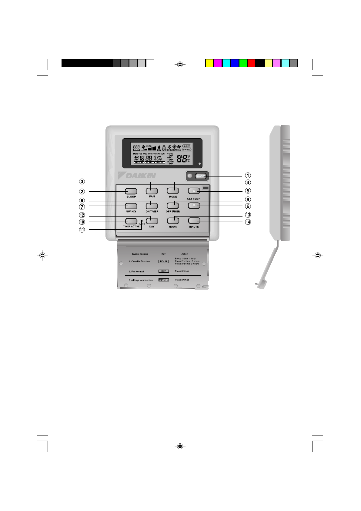
Events Togging
1 . O ver rid e F u nc tion
2 . F a n k ey loc k
3 . A ll key s loc k fu nc tion
K ey A c tion
H O U R
D A Y
M IN U TE
- P ress 1 tim e, 1 h ou r
- P ress 2 nd tim e, 2 h ou rs
- P ress 3 r d tim e, 3 h ou rs
- P ress 3 tim es
- P ress 3 tim es
OPERATING
M ANU AL
M o d e ls
M ERC A
En g lis h
O p e ra tin g M a n u a l
H a n d s e t W ire d
D e u ts c h
B e d ie n u n g s a n le itu n g
V e rd ra h te te s H a n d g e rä t
F r a n ç a is
M o d e D ’e m p lo i
C o m b in é C â b lé
Ne d e r la n d s
B e d ie n in g s a a n w ijz in g
B e d ra a d H a n d a p p a ra a t
Es p a ñ o l
M a n u a l D e In s tru c c io n e s
A u ric u la r A lá m b ric o
Ita lia n o
M a n u a le D i F u n z io n a m e n to
R ic e v ito re C a b la to
Ελληνικά
Εγχειρίδιο Οδηγιών
Α σ ύ ρµ α τ η Χ ειροσ υ σ κ ευ ή
Po r t u g u e s
M a n u a l D e F u n c io n a m e n to
A p a re lh o C o n e c ta d o
Pycckий
Руководство По Зксплуатации
Пр оводн ое Д истан цион н ое У пр авле н ие
TürkçeTürkçe
TürkçeTürkçe
Türkçe
K u lla n ım K ıla v u z u
K a b lo lu K u m a n d a
OM-NET3-0906-Daikin_EN 3/5/07, 9:58 AM10
Page 2
8
i
OM-NET3-0906-Daikin_EN 3/5/07, 9:58 AM8
Page 3

1
NO KEY FUNCTION
1 . ON/OFF On/Off the unit with overriding all the timer settings
2 . S LEEP Activate/deactivate S leep function
3 . FAN S elect Fan speeds control (Auto/High/Med/L ow)
4 . MODE S elect operating Modes control (Cool/Heat/Auto/Dry /Fan)
5 . S ET TEMP UP Increase set temperature in ° C or ° F
6 . S ET TEMP DOW N Decrease set temperature in ° C or ° F
7 . S W ING Activate/deactivate S wing control
8 . ON TIMER E nable/disable the E vent 1, 2 and 3 ON T IME R setting mode
9 . OFF TIMER E nable/disable the E vent 1, 2 and 3 OFF T IME R setting mode
1 0 . TIMER ACTIV E Activate/deactivate all set timers
1 1 . CLOCK E nable/disable the Real T ime Clock ( RT C) setting mode
1 2 . DAY a) S elect the day for RT C or timer setting
b) E nable/disable FAN K ey lock
1 3 . H OUR a) S elect the hour for RT C or timer settings
b) S et Override function for 1, 2 or 4 hours
1 4 . MINUTE a) S elect the minute for RT C or timer settings
b) E nable/disable k ey lock
1.0 OPERATING GUIDE
T here are all together 14 k ey s on the wired controller.
N ote : Override Function
P ress the HOU R k ey once will activate the override function for 1 hour. An indicator “H1” will show
on the top left corner of the L CD. P ress the same k ey again will increase the setting to 2 hours. An
indicator “H2 ” will be shown. P ress the 3 rd times increase the setting to 4 hours. An indicator “H4 ”
will be shown. S ubseq uent press will deactivate the override function.
When the Override function is activated, all the timers will by passed and turn ON the unit for a fix
periods of 1 hour, 2 hours or 4 hours depends on the selection, after which it will turned off.
OM-NET3-0906-Daikin_EN 3/5/07, 9:58 AM1
Page 4

2
1.1 ON/OFF Button
• Starting Operation:
When the unit is turned off, press the ON/OFF button.
The operation LED lights and the unit is turned on.
• Stopping Operation:
When the unit is turned on, press the ON/OFF button. The operation LED is extinguished
and control are turned off.
1.2 SLEEP Button
Press SLEEP button to activate the sleep mode or energy saving mode.
1.3 FAN Button
Press FAN button to select
AUTO,HIG H,MEDIUM
or
L OW
fan speed.
1.4 MODE Button
Press the MODE button to switch operation from
C OOL,HEAT,AUTO, DRY,FAN
.
The Auto mode is unavailable for Chilled Water (CW) system.
The Auto mode is unavailable for Chilled Water (CW) 2 pipe system.
It is available for Chilled Water (CW) 4 pipe system.
Check the display to see in which mode the control is set.
1.5 ‘’ or ‘’ Set Temperature Button
Press the temperature button and set the temperature of your choice. By pressing the ‘’ or
‘’ button once, temperature changes by 1°C [or 1°F].
Temperature can be set within the range 16 °C~ 30°C (6 1°F~ 86 °F) or 20°C~ 30°C (6 8°F~ 86 °F).
The range can be set by adjusting the shunt jumper behind the LCD remote (refer table below).
During fan mode, temperature can not be set.
If pressing ‘’ and ‘’ together, the unit of temperature will change from °C to °F and
vice-versa.
1.6 SWING button
Press SWING button to activate the air sweep function.
1.7 Tim e Setting
i) Set Real Time Clock Setting
Press CLOCK key one time will activate RTC setting mode. Pressing the same key again
will disable RTC setting mode.
Under RTC setting mode, “SET CLOCK” will be shown on LCD and it will blink at 0.5 sec
interval. The RTC and Day setting can be changed by pressing DAY key, HOUR key or
MINUTE key. If there is no further time related (DAY , HOUR and MINUTE) key is pressed
for 15 sec, the unit will quit from the CLOCK setting mode.
ii)
7 -Day Programmable Timers
The unit has 3 event functions, each event has an ON TIMER and an OFF TIMER.
Press the timer key (ON TIMER or OFF TIMER) will enable Event 1 timer setting mode.
Press the same key again will enable Event 2 timer setting mode. Press the 3rd times will
enable the Event 3 (Event handset) timer- setting mode. Subsequent key pressed the unit
will quit from timer setting mode.
All timers are event triggered timers and can be overridden by the ON/OFF button and
Override function.
iii)
Set Event 1 and Event 2 Timers
Under timer setting mode, “SET TIMER” will be shown on LCD and blink at 0.5 sec interval.
For Event 1 Timer setting, ‘
ON’ or ‘ OFF’ indication will appear and digit “1” will be
displayed on the top left corner of the LCD. ‘ ON’ or ‘ OFF’ indication and digit “2”
will be displayed during Event 2 timer setting. The timer setting can be changed through
pressing the DAY key, HOUR key or MINUTE key. If there is no further time related (DAY ,
HOUR and MINUTE) key is pressed, the unit will quit from the timer setting mode.
J um per 20 - 30 Application
SET Set temp range : 20°C ~ 30°C (6 8°F ~ 86 °F)
OFF Set temp range : 16 °C ~ 30°C (6 1°F ~ 86 °F)
ENGLISH
ENGLISH
OM-NET3-0906-Daikin_EN 3/5/07, 9:58 AM2
Page 5

3
iv) Set Event 3 Timer via remote control (Optional)
This timer can be controlled separately through remote control as well as ON TIMER or
OFF TIMER keys. Timer 3 can be set like timers 1 and 2 like above except the DAY setting
is not provided as this timer setting is valid everyday. An indicator ‘3’ will display during the
Event 3 timer setting mode. ‘
ON’ or ‘ OFF’ will blink at 0.5 sec interval during the
timer setting. If there is no futher time related (DAY, HOUR and MINUTE) key is pressed,
the unit will quit from the timer setting mode.
The ON/OFF timer setting received from remote control will override the Event 3 timer
setting from the unit.
1.8 Activating and canceling timers
These timers will not triggered if the timer is not active. To activate the timers, press the TIMER
ACTIVE key unit “TIMER ACTIVE” appears on LCD. This symbol is to indicate Event 1, Event
2 and/or Event 3 timers are active. Pressing the same steps will deactivate the timers and
“TIMER ACTIVE” symbol will disappear.
Another method to cancel the timers setting is changed all the hour setting of the timers to null
one by one. When the setting is null, the LCD display --:--, then this respective timer will be
disable.
1.9 Key Lock
These key lock function to inhibit any setting change. Press the MINUTE key 3 times
consecutively will activate key lock function, “KEYLOCK” will be shown on LCD. Upon all the
keys are locked, only ON/OFF key and MINUTE key can be pressed. To cancel the key lock
function, press the MINUTE key 3 times consecutively, the word “KEYLOCK” disappear.
1.10 Fan Lock
When the DAY key is press 3 times consecutively within 1.5 sec, the fan symbol (shown
above) will disappear and fan key will be inhibited. Press the DAY key 3 times to cancel the fan
lock function.
1.11 B attery B ack up
Battery backup is used to retain the RTC and 7-days programmable timer settings during
power down. For unit without battery backup, the default setting will be 12:00 am the timer will
clear during power up.
2.0 ERROR INDICATOR
If any abnormal condition detected, an error code will be shown. When the transmission line
between the main board and the unit line is opened, an error code ‘EOP’ will be shown. For
those errors detected from main board, the format of error code will be as following:
DX System:
CW System:
Error 7 Segments
Room sensor missing/short E1
Indoor coil sensor missing/short E2
Outdoor coil sensor missing/short E3
Compressor overload E4
Outdoor abnormal compressor overload trip or gas leak E5
Condensate water pump fault E6
Error 7 Segments
Room sensor error E1
Pipe water sensor error E2
Pipe water fault E5
Water pump error E6
OM-NET3-0906-Daikin_EN 3/5/07, 9:58 AM3
Page 6

4
3.0 INSTALLATION OF LCD REMOTE CONTROLLER
3.1 Accessories
The following accessories are included together with this manual. If any part is missing,
contact your dealer immediately.
1 Remote controller
2 Wooden screw 4.1 x 16 (2 pieces) & machine screw (2 pieces)
3 Instruction manual
4 Battery
5 Connection wire
3.2 Step-b y-step guide
i) First, open up the casing of the LCD remote controller into its top and bottom case
using a screwdriver. To do this, insert the screwdriver into the lower slot and slide it in
the outward direction.
ii) Fix the bottom case onto the wall with the 2 wooden screws provided.
Then, insert the 4-pin connection wires (from main board) through the slot on the upper
center of the case as shown below.
iii) To select cooling only model or heatpump model, some adjustment required in the
shunt jumper setting.
iv) Fasten back the top and bottom case into place. Hook the two upper claws into their
respective slots and snap the lower part shut.
Lower slot
for opening LCD
casing
LCD Remote
(Bottom case)
LCD Remote
(Top case)
2 x Wooden
screw
Connection
wires
SHUNT JUMPER SETTING FOR MODEL SELECTION
J H JD Application Model/Remark
OFF OFF AUTO DETECT Depends on main board
OFF SET CW & DX system Export cool (EC)
SET OFF CW & DX system Heatpump (HP)
SET SET AUTO DETECT Auto heatpump (AP)
* The AUTO DETECT is unavailable for Chilled Water (CW) System.
ENGLISH
ENGLISH
OM-NET3-0906-Daikin_EN 3/5/07, 9:58 AM4
 Loading...