

Daikin HXY080A8V1BF, HXY125A8V1BF Operation manuals
INSTALLATION AND
OPERATION MANUAL
System indoor unit
HXY080A8V1BF
HXY125A8V1BF

:
atakse vastavalt meie juhenditele:
25 Deǧiştirilmiş halleriyle Yönetmelikler.
24 Smernice, v platnom znení.
23 Direktīvās un to papildinājumos.
22 Direktyvose su papildymais.
21 Директиви, с техните изменения.
20 Direktiivid koos muudatustega.
19 Direktive z vsemi spremembami.
CE - UYUMLULUK-BEYANI
CE - VYHLÁSENIE-ZHODY
CE - ATBILSTĪBAS-DEKLARĀCIJA
CE - ATITIKTIES-DEKLARACIJA
декларация:
.
seit
<A> DAIKIN.TCF.025J07/10-2020
<B> DEKRA (NB0344)
<C> 2082543.0551-QUA/EMC
e oprávnená vytvoriť súbor technickej konštrukcie.
irányelv(ek) és módosításaik rendelkezé
Direktiivejä, sellaisina kuin ne ovat muutettuina.
10 Direktiver, med senere ændringer.
11 Direktiv, med företagna ändringar.
zną odpowiedzialność, że urządzenia, których ta deklaracja dotyczy:
CE - ДЕКЛАРАЦИЯ-ЗА-ϹЪОТВЕТСТВИЕ
CE - VASTAVUSDEKLARATSIOON
CE - IZJAVA O SKLADNOSTI
declară pe proprie răspundere că echipamentele la care se referă această declaraţie:
r
18
z vso odgovornostjo izjavlja, da je oprema naprav, na katero se izjava nanaša:
o
19
kinnitab oma täielikul vastutusel, et käesoleva deklaratsiooni alla kuuluv varustus:
x
20
декларира на своя отговорност, че оборудването, за коeто се отнася тази
b
21
visiška savo atsakomybe skelbia, kad įranga, kuriai taikoma ši deklaracija:
t
22
ar pilnu atbildību apliecina, ka tālāk aprakstītās iekārtas, uz kurām attiecas šī deklarācija:
v
23
vyhlasuje na vlastnú zodpovednosť, že zariadenie, na ktoré sa vzťahuje toto vyhlásenie:
k
24
tamamen kendi sorumluluǧunda olmak üzere bu bildirinin ilgili olduǧu donanımının aşaǧıdaki gibi olduǧunu beyan eder:
w
25
rukcjami:
inst
conformitate cu instrucţiunile noastre:
17 spełniają wymogi następujących norm i innych dokumentów normalizacyjnych, pod warunkiem że używane są zgodnie z naszymi
16 megfelelnek az alábbi szabvány(ok)nak vagy egyéb irányadó dokumentum(ok)nak, ha azokat előírás szerint használják:
18 sunt în conformitate cu următorul (următoarele) standard(e) sau alt(e) document(e) normativ(e), cu condiţia ca acestea să fie utilizate în
овии их использования согласно нашим
инструкции:
20 on vastavuses järgmis(t)e standardi(te)ga või teiste normatiivsete dokumentidega, kui neid kasut
19 skladni z naslednjimi standardi in drugimi normativi, pod pogojem, da se uporabljajo v skladu z našimi navodili:
21 съответстват на следните стандарти или други нормативни документи, при условие, че се използват съгласно нашите
s našim návodom:
23 tad, ja lietoti atbilstoši ražotāja norādījumiem, atbilst sekojošiem standartiem un citiem normatīviem dokumentiem
22 atitinka žemiau nurodytus standartus ir (arba) kitus norminius dokumentus su sąlyga, kad yra naudojami pagal mūsų nurodymus:
25 ürünün, talimatlarımıza göre kullanılması koşuluyla aşağıdaki standartlar ve norm belirten belgelerle uyumludur:
24 sú v zhode s nasledovnou(ými) normou(ami) alebo iným(i) normatívnym(i) dokumentom(ami), za predpokladu, že sa používajú v súlade
bo normativním dokumentům:
deklaruje na własną i wyłąc
m
17
CE - DECLARAŢIE-DE-CONFORMITATE
CE - DEKLARACJA-ZGODNOŚCI
CE - MEGFELELŐSÉGI-NYILATKOZAT
CE - IZJAVA-O-USKLAĐENOSTI
относится настоящее заявление:
у
к котором
12 Direktiver, med foretatte endringer.
03 Directives, telles que modifiées.
02 Direktiven, gemäß Änderung.
01 Directives, as amended.
HODĚ
оборудование,
CE - PROHLÁŠENÍ-O-S
CE - ILMOITUS-YHDENMUKAISUUDESTA
CE - ERKLÆRING OM-SAMSVAR
16
15 Smjernice, kako je izmijenjeno.
13
14 v platném znění.
n lo enmendado.
05 Directivas, segú
04 Richtlijnen, zoals geamendeerd.
**
18 Directivelor, cu amendamentele respective.
17 z późniejszymi poprawkami.
v súlade s osvedčením <C>.
vērtējumam saskaņā ar sertifikātu <C>.
pagal Sertifikatą <C>.
от <B> съгласно Сертификата <C>.
24 Poznámka * ako bolo uvedené v <A> a pozitívne zistené <B>
23 Piezīmes * kā norādīts <A> un atbilstoši <B> pozitīvajam
22 Pastaba * kaip nustatyta <A> ir kaip teigiamai nuspręsta <B>
21 Забележка * както е изложено в <A> и оценено положително
09 Директив со всеми поправками.
08 Directivas, conforme alteração em.
07 Οδηγιών, όπως έχουν τροποποιηθεί.
06 Direttive, come da modifica.
*
v skladu s certifikatom <C>.
de <B> în conformitate cu Certificatul <C>.
<B> i Świadectwem <C>.
a(z) <C> tanúsítvány szerint.
6 Megjegyzés * a(z) <A> alapján, a(z) <B> igazolta a megfelelést,
1
19 Opomba * kot je določeno v <A> in odobreno s strani <B>
18 Notă * aşa cum este stabilit în <A> şi apreciat pozitiv
17 Uwaga * zgodnie z dokumentacją <A>, pozytywną opinią
Machinery 2006/42/EC
nts av <B> enligt
kin Europe N.V. je pooblaščen za sestavo datoteke s tehnično mapo.
19 ** Dai
20 ** Daikin Europe N.V. on volitatud koostama tehnilist dokumentatsiooni.
<B> tarafından olumlu olarak değerlendirildiği gibi.
* <A>’da belirtildiği gibi ve <C> Sertifikasına göre
25 Not
právnění ke kompilaci souboru technické konstrukce.
idetud <B> järgi vastavalt sertifikaadile <C>.
ki
20 Märkus * nagu on näidatud dokumendis <A> ja heaks
14 ** Společnost Daikin Europe N.V. má o
13 ** Daikin Europe N.V. on valtuutettu laatimaan Teknisen asiakirjan.
24 ** Spoločnosť Daikin Europe N.V. j
23 ** Daikin Europe N.V. ir autorizēts sastādīt tehnisko dokumentāciju.
22 ** Daikin Europe N.V. yra įgaliota sudaryti šį techninės konstrukcijos failą.
21 ** Daikin Europe N.V. е оторизирана да състави Акта за техническа конструкция.
15 ** Daikin Europe N.V. je ovlašten za izradu Datoteke o tehničkoj konstrukciji.
25 ** Daikin Europe N.V. Teknik Yapı Dosyasını derlemeye yetkilidir.
18 ** Daikin Europe N.V. este autorizat să compileze Dosarul tehnic de construcţie.
17 ** Daikin Europe N.V. ma upoważnienie do zbierania i opracowywania dokumentacji konstrukcyjnej.
16 ** A Daikin Europe N.V. jogosult a műszaki konstrukciós dokumentáció összeállítására.
Electromagnetic Compatibility 2014/30/EU
od strane <B> prema Certifikatu <C>.
v souladu s osvědčením <C>.
hyväksynyt Sertifikaatin <C> mukaisesti.
bedømmelse av <B> ifølge Sertifikat <C>.
Certifikatet <C>.
erklærer et fullstendig ansvar for at det utstyr som berøres av denne deklarasjon innebærer at:
erklærer under eneansvarlig, at udstyret, som er omfattet af denne erklæring:
заявляет, исключительно под свою ответственность, что
deklarerar i egenskap av huvudansvarig, att utrustningen som berörs av denna deklaration innebär att:
n
q
u
s
12
11
10
09
CE - FÖRSÄKRAN-OM-ÖVERENSTÄMMELSE
CE - OVERENSSTEMMELSESERKLÆRING
CE - ЗАЯВЛЕНИЕ-О-СООТВЕТСТВИИ
CE - DECLARAÇÃO-DE-CONFORMIDADE
ing heeft:
CE - ΔHΛΩΣΗ ΣΥΜΜΟΡΦΩΣΗΣ
CE - DICHIARAZIONE-DI-CONFORMITA
CE - DECLARACION-DE-CONFORMIDAD
ilmoittaa yksinomaan omalla vastuullaan, että tämän ilmoituksen tarkoittamat laitteet:
j
13
prohlašuje ve své plné odpovědnosti, že zařízení, k němuž se toto prohlášení vztahuje:
c
14
izjavljuje pod isključivo vlastitom odgovornošću da oprema na koju se ova izjava odnosi:
y
15
teljes felelőssége tudatában kijelenti, hogy a berendezések, melyekre e nyilatkozat vonatkozik:
h
16
acordo com as nossas instruções:
инструкциям:
09 соответствуют следующим стандартам или другим нормативным документам, при усл
10 overholder følgende standard(er) eller andet/andre retningsgivende dokument(er), forudsat at disse anvendes i henhold til vore
08 estão em conformidade com a(s) seguinte(s) norma(s) ou outro(s) documento(s) normativo(s), desde que estes sejam utilizados de
tive utstyr er i overensstemmelse med følgende standard(er) eller andre normgivende dokument(er), under forutssetning av at
förutsättning att användning sker i överensstämmelse med våra instruktioner:
instrukser:
11 respektive utrustning är utförd i överensstämmelse med och följer följande standard(er) eller andra normgivande dokument, under
eer andere bindende documenten zijn, op voorwaarde dat ze worden gebruikt overeenkomstig
mukaisesti:
disse brukes i henhold til våre instrukser:
12 respek
14 za předpokladu, že jsou využívány v souladu s našimi pokyny, odpovídají následujícím normám ne
13 vastaavat seuraavien standardien ja muiden ohjeellisten dokumenttien vaatimuksia edellyttäen, että niitä käytetään ohjeidemme
15 u skladu sa slijedećim standardom(ima) ili drugim normativnim dokumentom(ima), uz uvjet da se oni koriste u skladu s našim uputama:
24 održiavajúc ustanovenia:
23 ievērojot prasības, kas noteiktas:
22 laikantis nuostatų, pateikiamų:
21 следвайки клаузите на:
20 vastavalt nõuetele:
19 ob upoštevanju določb:
15 prema odredbama:
14 za dodržení ustanovení předpisu:
13 noudattaen määräyksiä:
11 enligt villkoren i:
12 gitt i henhold til bestemmelsene i:
10 under iagttagelse af bestemmelserne i:
:
11 Information * enligt <A> och godkä
12 Merk * som det fremkommer i <A> og gjennom positiv
25 bunun koşullarına uygun olarak:
niami Dyrektyw:
17 zgodnie z postanowie
16 követi a(z):
θορίζεται στο <A> και κρίνεται θετικά από
da <B> secondo il Certificato <C>.
το <B> σύμφωνα με το Πιστοποιητικό <C>.
07 Σημείωση * όπως κα
06 Nota * delineato nel <A> e giudicato positivamente
18 în urma prevederilor:
t <C>.
gemäß Zertifika
according to the Certificate <C>.
15 Napomena * kako je izloženo u <A> i pozitivno ocijenjeno
14 Poznámka * jak bylo uvedeno v <A> a pozitivně zjištěno <B>
13 Huom * jotka on esitetty asiakirjassa <A> ja jotka <B> on
Свидетельству <C>.
с положительным решением <B> согласно
positivo de <B> de acordo com o Certificado <C>.
10 Bemærk * som anført i <A> og positivt vurderet af <B>
09 Примечание * как указано в <A> и в соответствии
08 Nota * tal como estabelecido em <A> e com o parecer
positivamente por <B> de acuerdo con el
<B> overeenkomstig Certificaat <C>.
<B> conformément au Certificat <C>.
ь Комплект технической документации.
Hiromitsu Iwasaki
Director
Ostend, 3rd of May 2021
12 ** Daikin Europe N.V. har tillatelse til å kompilere den Tekniske konstruksjonsfilen.
09 ** Компания Daikin Europe N.V. уполномочена составит
08 ** A Daikin Europe N.V. está autorizada a compilar a documentação técnica de fabrico.
07 ** Η Daikin Europe N.V. είναι εξουσιοδοτημένη να συντάξει τον Τεχνικό φάκελο κατασκευής.
i henhold til Certifikat <C>.
Certificado <C>.
11 ** Daikin Europe N.V. är bemyndigade att sammanställa den tekniska konstruktionsfilen.
10 ** Daikin Europe N.V. er autoriseret til at udarbejde de tekniske konstruktionsdata.
stellen.
verklaart hierbij op eigen exclusieve verantwoordelijkheid dat de apparatuur waarop deze verklaring betrekk
déclare sous sa seule responsabilité que l'équipement visé par la présente déclaration:
erklärt auf seine alleinige Verantwortung daß die Ausrüstung für die diese Erklärung bestimmt ist:
declares under its sole responsibility that the equipment to which this declaration relates:
l
f
d
a
CE - CONFORMITEITSVERKLARING
CE - DECLARATION-DE-CONFORMITE
CE - KONFORMITÄTSERKLÄRUNG
CE - DECLARATION-OF-CONFORMITY
Daikin Europe N.V.
04
03
02
01
declara bajo su única responsabilidad que el equipo al que hace referencia la declaración:
e
05
dichiara sotto la propria responsabilità che gli apparecchi a cui è riferita questa dichiarazione:
i
06
δηλώνει με αποκλειστική της ευθύνη ότι ο εξοπλισμός στον οποίο αναφέρεται η παρούσα δήλωση:
g
07
declara sob sua exclusiva responsabilidade que os equipamentos a que esta declaração se refere:
p
08
ostre istruzioni:
n
daß sie gemäß unseren Anweisungen eingesetzt werden:
HXY080A8V1BF, HXY125A8V1BF,
instructions:
03 sont conformes à la/aux norme(s) ou autre(s) document(s) normatif(s), pour autant qu'ils soient utilisés conformément à nos instructions:
02 der/den folgenden Norm(en) oder einem anderen Normdokument oder -dokumenten entspricht/entsprechen, unter der Voraussetzung,
01 are in conformity with the following standard(s) or other normative document(s), provided that these are used in accordance with our
nuestras instrucciones:
onze instructies:
04 conform de volgende norm(en) of één of m
05 están en conformidad con la(s) siguiente(s) norma(s) u otro(s) documento(s) normativo(s), siempre que sean utilizados de acuerdo con
με τις οδηγίες μας:
06 sono conformi al(i) seguente(i) standard(s) o altro(i) documento(i) a carattere normativo, a patto che vengano usati in conformità alle
07 είναι σύμφωνα με το(α) ακόλουθο(α) πρότυπο(α) ή άλλο έγγραφο(α) κανονισμών, υπό την προϋπόθεση ότι χρησιμοποιούνται σύμφωνα
03 conformément aux stipulations des
02 gemäß den Vorschriften der:
01 following the provisions of:
EN60335-2-40,
07 με τήρηση των διατάξεων των:
08 de acordo com o previsto em:
06 secondo le prescrizioni per:
05 siguiendo las disposiciones de:
04 overeenkomstig de bepalingen van:
02 Hinweis * wie in <A> aufgeführt und von <B> positiv beurteilt
01 Note * as set out in <A> and judged positively by <B>
09 в соответствии с положениями:
05 Nota * como se establece en <A> y es valorado
04 Bemerk * zoals vermeld in <A> en positief beoordeeld door
03 Remarque * tel que défini dans <A> et évalué positivement par
04 ** Daikin Europe N.V. is bevoegd om het Technisch Constructiedossier samen te
03 ** Daikin Europe N.V. est autorisé à compiler le Dossier de Construction Technique.
02 ** Daikin Europe N.V. hat die Berechtigung die Technische Konstruktionsakte zusammenzustellen.
01 ** Daikin Europe N.V. is authorised to compile the Technical Construction File.
06 ** Daikin Europe N.V. è autorizzata a redigere il File Tecnico di Costruzione.
05 ** Daikin Europe N.V. está autorizado a compilar el Archivo de Construcción Técnica.
3P402254-11F
HXY080A8V1BF
HXY125A8V1BF
VRV IV System indoor unit
Installation and
operation manual
Content Page
1. About the documentation........................................................... 2
1.1. About this document ...................................................................... 2
1.2. Scope of the manual ...................................................................... 2
1.3. Documentation set ......................................................................... 2
2. General safety precautions........................................................ 2
2.1. For the user .................................................................................... 2
2.2. For the installer .............................................................................. 2
2.2.1. General............................................................................... 2
2.2.2. Installation site.................................................................... 3
2.2.3. Refrigerant.......................................................................... 3
2.2.4. Water.................................................................................. 3
2.2.5. Electrical............................................................................. 3
2.2.6. Meaning of used items ....................................................... 4
3. About the box............................................................................. 4
3.1. Indoor unit ...................................................................................... 4
3.1.1. To unpack the indoor unit ................................................... 4
3.1.2. To remove the accessories from the indoor unit................. 4
4. About the units and options ....................................................... 5
4.1. General information........................................................................ 5
4.1.1. Identification label: Indoor unit............................................ 5
4.2. Possible combinations of units and options ................................... 5
4.2.1. List of options for indoor unit .............................................. 5
4.2.2. Possible combinations of indoor unit and outdoor unit....... 6
5. Application guidelines................................................................ 6
5.1. Overview: Application guidelines.................................................... 6
5.2. Setting up the space heating/cooling system................................. 6
5.3. Using an auxiliary heat source ....................................................... 7
6. Preparation ................................................................................ 7
6.1. Preparing installation site ............................................................... 7
6.1.1. Installation site requirements of the indoor unit.................. 7
6.2. Preparing water circuit ................................................................... 8
6.2.1. Selection of the type of heat emitters................................. 8
6.2.2. Water circuit requirements.................................................. 9
6.2.3. Formula to calculate the expansion vessel pre-pressure... 9
6.2.4. To check the water volume................................................. 9
6.2.5. Changing the pre-pressure of the expansion vessel........ 10
6.2.6. To check the water volume: Examples............................. 10
6.3. Preparing electrical wiring .............................................................11
6.3.1. About preparing electrical wiring .......................................11
6.3.2. Overview of electrical connections on the indoor unit .......11
7. Installation................................................................................ 12
7.1. Mounting the indoor unit............................................................... 12
7.1.1. To install the indoor unit.................................................... 12
7.2. Connecting the water piping......................................................... 13
7.2.1. To connect the water piping.............................................. 13
7.3. Connecting the electrical wiring ................................................... 14
7.3.1. Precautions on electrical wiring work ............................... 14
7.4. Finishing the indoor unit installation ............................................. 16
7.4.1. To fix the user interface cover to the indoor unit............... 16
7.4.2. To close the indoor unit..................................................... 16
8. Commissioning ........................................................................ 17
8.2. Final air purging ........................................................................... 17
8.3. Field settings ................................................................................ 17
8.3.1. Procedure......................................................................... 17
8.3.2. Detailed description.......................................................... 18
8.4. Field setting list for Installation Manual ........................................ 22
8.5. Final check and test run ............................................................... 24
8.5.1. Final check ....................................................................... 24
8.5.2. System test run................................................................. 24
8.5.3. Indoor unit individual test run............................................ 24
8.6. Service and maintenance............................................................. 25
8.6.1. Maintenance activities ...................................................... 25
8.6.2. Malfunction codes list ....................................................... 25
8.6.3. Important information regarding the refrigerant used....... 25
9. Installing the optional EKBUHAA(6V3/6W1) heater kit............ 26
10. Hand-over to the user ..............................................................26
11. Operation of the unit ................................................................ 27
11.1. Introduction .................................................................................. 27
11.1.1. General information.......................................................... 27
11.2. Quick start-up of the unit.............................................................. 27
11.2.1. Space cooling/heating operation ...................................... 27
11.3. Operating the unit......................................................................... 27
11.3.1. Operating the user interface............................................. 27
11.3.2. Name and function of buttons and icons .......................... 28
11.3.3. Setting up the controller ................................................... 29
11.3.4. Space cooling operation ( ) ............................................ 29
11.3.5. Space heating operation ( )............................................ 29
11.3.6. Other operation modes..................................................... 31
11.3.7. Temperature read-out mode............................................. 31
11.3.8. Schedule timer operation ................................................. 32
11.3.9. Space heating .................................................................. 32
11.3.10. Programming and consulting the schedule timer ............. 33
11.3.11. Operating the optional demand PCB................................ 37
11.3.12. Operating the optional user interface ............................... 37
11.4. Field settings................................................................................ 37
11.4.1. Procedure......................................................................... 37
11.5. Field setting list for Operation Manual.......................................... 38
12. Maintenance ............................................................................ 40
12.1. Important information regarding the refrigerant used................... 40
12.2. Maintenance activities.................................................................. 40
13. Troubleshooting .......................................................................40
13.1. Malfunction codes list................................................................... 40
14. Technical Data ......................................................................... 40
14.1. Piping diagram ............................................................................. 40
14.2. Wiring diagram............................................................................. 41
14.3. Electrical components box ........................................................... 42
14.4. Operation range HXY(080/125) ................................................... 42
14.5. ESP curve .................................................................................... 42
14.6. Technical specifications table
14.7. Electrical specifications table ....................................................... 43
....................................................... 43
15. Disposal requirements .............................................................43
The English text is the original instruction. Other languages are
translations of the original instructions.
HXY080+125A8V1BF
VRV IV System indoor unit
4P405267-1C – 2021.04
Installation and operation manual
1
1. About the documentation
1.1. About this document
Units are marked with the following symbol:
This document is an installation manual. It is intended for authorized
installers of this product. It describes the procedures for installing,
commissioning and maintaining the unit, and it will provide help if
problems occur. Carefully read the relevant parts of the manual.
This document is also an operation manual. It is intended for the
installer and the user of this product. It describes how to operate and
maintain the unit, and it will provide help if problems occur. Carefully
read the relevant parts of the manual.
1.2. Scope of the manual
This manual does NOT include the selection procedure and the water
system design procedure. Only some precautions and tips and tricks
about the design of the water circuit are given in a separate chapter
of this manual.
Once the selection is done and the water system is designed, this
manual describes the procedures for handling, installing and
connecting the HXY080/125 units. This manual has been prepared to
ensure adequate maintenance of the unit, and it will provide help if
problems occur.
1.3. Documentation set
This document is part of a documentation set. The complete set
consists of:
Document Contains… Format
Indoor unit
installation/operation
manual
Outdoor unit installation
manual
Latest revisions of the supplied documentation may be available on
the regional Daikin website or via your dealer.
Installation and
operator instructions
See info delivered with
outdoor unit.
Indoor unit
installation/operation
manual
This means that electrical and electronic products may not be
mixed with unsorted household waste. Do NOT try to dismantle
the system yourself: the dismantling of the system, treatment of
the refrigerant, of oil and of other parts must be done by an
authorized installer and must comply with applicable legislation.
Units must be treated at a specialized treatment facility for
reuse, recycling and recovery. By ensuring this product is
disposed of correctly, you will help to prevent potential negative
consequences for the environment and human health. For more
information, contact your installer or local authority.
2.2. For the installer
2.2.1. General
If you are not sure how to install or operate the unit, contact your
dealer.
NOTICE
Improper installation or attachment of equipment or
accessories could result in electric shock, short-circuit,
leaks, fire or other damage to the equipment. Only use
accessories, optional equipment and spare parts made or
approved by Daikin.
WARNING
Make sure installation, testing and applied materials
comply with applicable legislation (on top of the
instructions described in the Daikin documentation).
CAUTION
Wear adequate personal protective equipment (protective
gloves, safety glasses,…) when installing, maintaining or
servicing the system.
2. General safety precautions
2.1. For the user
If you are not sure how to operate the unit, contact your installer.
The appliance is not intended for use by persons, including
children, with reduced physical, sensory or mental capabilities,
or lack of experience and knowledge, unless they have been
given supervision or instruction concerning use of the appliance
by a person responsible for their safety. Children must be
supervised to ensure that they do not play with the product.
CAUTION
Do NOT rinse the unit. This may cause electric shocks or
fire.
NOTICE
Do NOT place any objects or equipment on top of the
unit.
Do NOT sit, climb or stand on the unit.
DANGER: RISK OF BURNING
Do NOT touch the refrigerant piping, water piping or
internal parts during and immediately after operation.
It could be too hot or too cold. Give it time to return to
normal temperature. If you must touch it, wear
protective gloves.
Do NOT touch any accidental leaking refrigerant.
In accordance with the applicable legislation, it might be necessary to
provide a logbook with the product containing at least: information on
maintenance, repair work, results of tests, stand-by periods,…
Also, at least, following information must be provided at an
accessible place at the product:
Instructions for shutting down the system in case of an
emergency.
Name and address of fire department, police and hospital.
Name, address and day and night telephone numbers for
obtaining service.
In Europe, EN378 provides the necessary guidance for this logbook.
Installation and operation manual
2
HXY080+125A8V1BF
VRV IV System indoor unit
4P405267-1C – 2021.04
2.2.2. Installation site
Provide sufficient space around the unit for servicing and air
circulation.
Make sure the installation site withstands the unit’s weight and
vibration.
Make sure the area is well ventilated.
Make sure the unit is level.
Do NOT install the unit in the following places:
In potentially explosive atmospheres.
In places where there is machinery that emits electromagnetic
waves. Electromagnetic waves may disturb the control system,
and cause malfunction of the equipment.
In places where there is a risk of fire due to the leakage of
flammable gases (example: thinner or gasoline), carbon fibre,
ignitable dust.
In places where corrosive gas (example: sulphurous acid gas) is
produced. Corrosion of copper pipes or soldered parts may
cause the refrigerant to leak.
2.2.3. Refrigerant
2.2.4. Water
NOTICE
Make sure water quality complies with EU directive
98/83 EC.
2.2.5. Electrical
DANGER: RISK OF ELECTROCUTION
Turn OFF all power supply before removing the
switch box cover, connecting electrical wiring or
touching electrical parts.
Disconnect the power supply for more than 1 minute,
and measure the voltage at the terminals of main
circuit capacitors or electrical components before
servicing. The voltage must be less than 50 V DC
before you can touch electrical components. For the
location of the terminals, see the wiring diagram.
Do NOT touch electrical components with wet hands.
Do NOT leave the unit unattended when the service
cover is removed.
NOTICE
Make sure refrigerant piping installation complies with
applicable legislation. In Europe, EN378 is the applicable
standard.
NOTICE
Make sure the field piping and connections are not
subjected to stress.
WARNING
During tests, NEVER pressurize the product with a
pressure higher than the maximum allowable pressure (as
indicated on the nameplate of the unit).
WARNING
Take sufficient precautions in case of refrigerant leakage. If
refrigerant gas leaks, ventilate the area immediately.
Possible risks:
Excessive refrigerant concentrations in a closed room
can lead to oxygen deficiency.
Toxic gas may be produced if refrigerant gas comes
into contact with fire.
WARNING
Always recover the refrigerants. Do NOT release them
directly into the environment. Use a refrigerant reclaim unit
to evacuate the installation.
Only use phosphoric acid deoxidised seamless copper with
annealed temper grade.
WARNING
If not factory installed, a main switch or other means for
disconnection, having a contact separation in all poles
providing full disconnection under overvoltage category III
condition, shall be installed in the fixed wiring.
WARNING
Only use copper wires.
All field wiring must be performed in accordance with
the wiring diagram supplied with the product.
NEVER squeeze bundled cables and make sure they
do not come in contact with the piping and sharp
edges. Make sure no external pressure is applied to
the terminal connections.
Make sure to install earth wiring. Do NOT earth the
unit to a utility pipe, surge absorber, or telephone
earth. Incomplete earth may cause electrical shock.
Make sure to use a dedicated power circuit. NEVER
use a power supply shared by another appliance.
Make sure to install the required fuses or circuit
breakers.
Make sure to install an earth leakage protector.
Failure to do so may cause electric shock or fire.
Install power cables at least 1 meter away from televisions or radios
to prevent interference. Depending on the radio waves, a distance of
1 meter may not be sufficient.
WARNING
After finishing the electrical work, confirm that each
electrical component and terminal inside the electrical
components box is connected securely.
Make sure all covers are closed before starting up the
unit.
HXY080+125A8V1BF
VRV IV System indoor unit
4P405267-1C – 2021.04
Installation and operation manual
3
2.2.6. Meaning of used items
21
Dealer:
Sales distributor for the product.
Authorized installer:
Technical skilled person who is qualified to install the product.
User:
Person who is owner of the product and/or operates the product.
Applicable legislation:
All international, European, national and local directives, laws,
regulations and/or codes that are relevant and applicable for a
certain product or domain.
Service company:
Qualified company which can perform or coordinate the required
service to the product.
Installation manual:
Instruction manual specified for a certain product or application,
explaining how to install, configure and maintain it.
Operation manual:
Instruction manual specified for a certain product or application,
explaining how to operate it.
Accessories:
Labels, manuals, information sheets and equipment that are
delivered with the product and that need to be installed
according to the instructions in the accompanying
documentation.
Optional equipment:
Equipment made or approved by Daikin that can be combined
with the product according to the instructions in the
accompanying documentation.
Field supply:
Equipment not made by Daikin that can be combined with the
product according to the instructions in the accompanying
documentation.
a
a Installation/operation manual
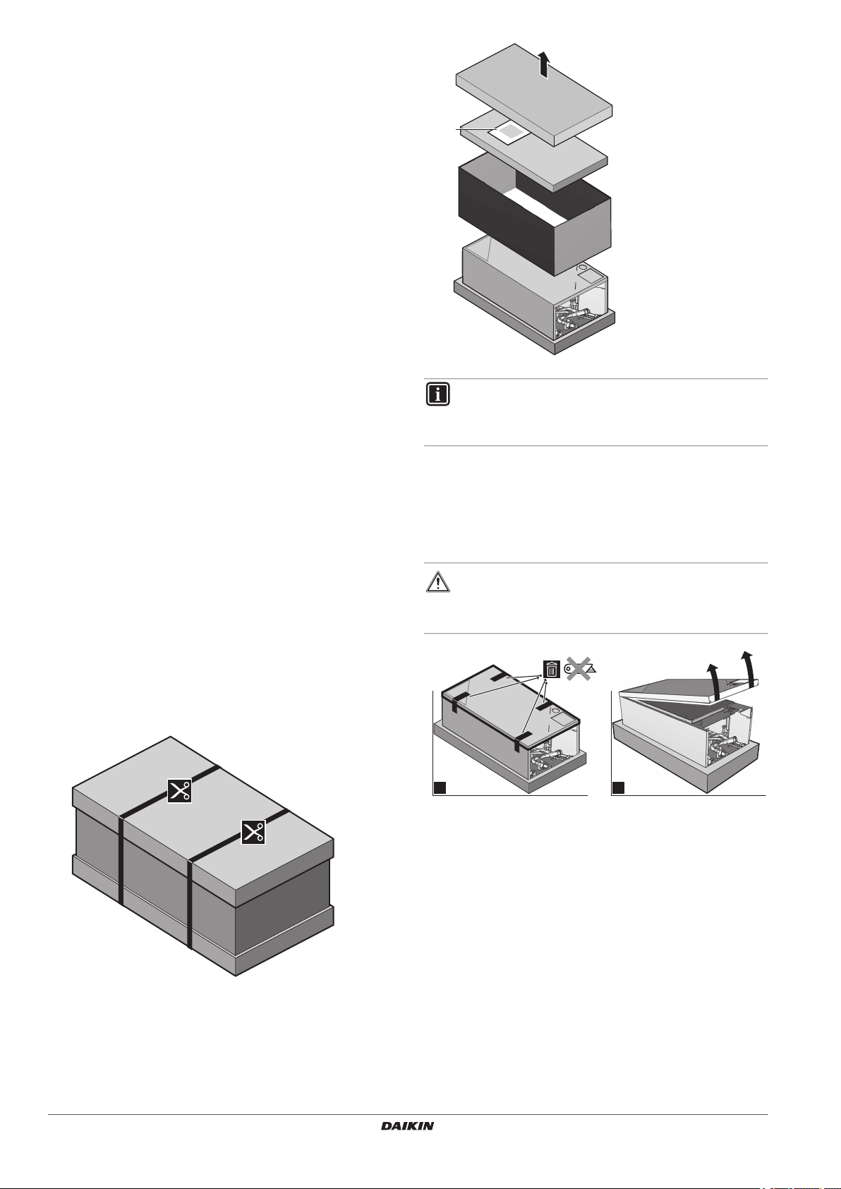
INFORMATION
Do NOT throw away the upper cardboard cover. On the
inside of the cardboard cover, the installation pattern is
printed.
3.1.2. To remove the accessories from the indoor unit
The installation/operation manual indoor unit is located in the upper
part of the box. Follow the procedure below to remove the other
accessories.
1 Unfix front panel.
2 Tilt the bottom side of the front panel upwards and remove it.
3. About the box
At delivery, the unit must be checked for damage. Any damage
must be reported immediately to the carrier’s claims agent.
Bring the packed unit as close as possible to its final installation
position to prevent damage during transport.
3.1. Indoor unit
3.1.1. To unpack the indoor unit
WARNING
Tear apart and throw away plastic packaging bags so that
children will not play with them. Children playing with
plastic bags face danger of death by suffocation.
Installation and operation manual
4
HXY080+125A8V1BF
VRV IV System indoor unit
4P405267-1C – 2021.04
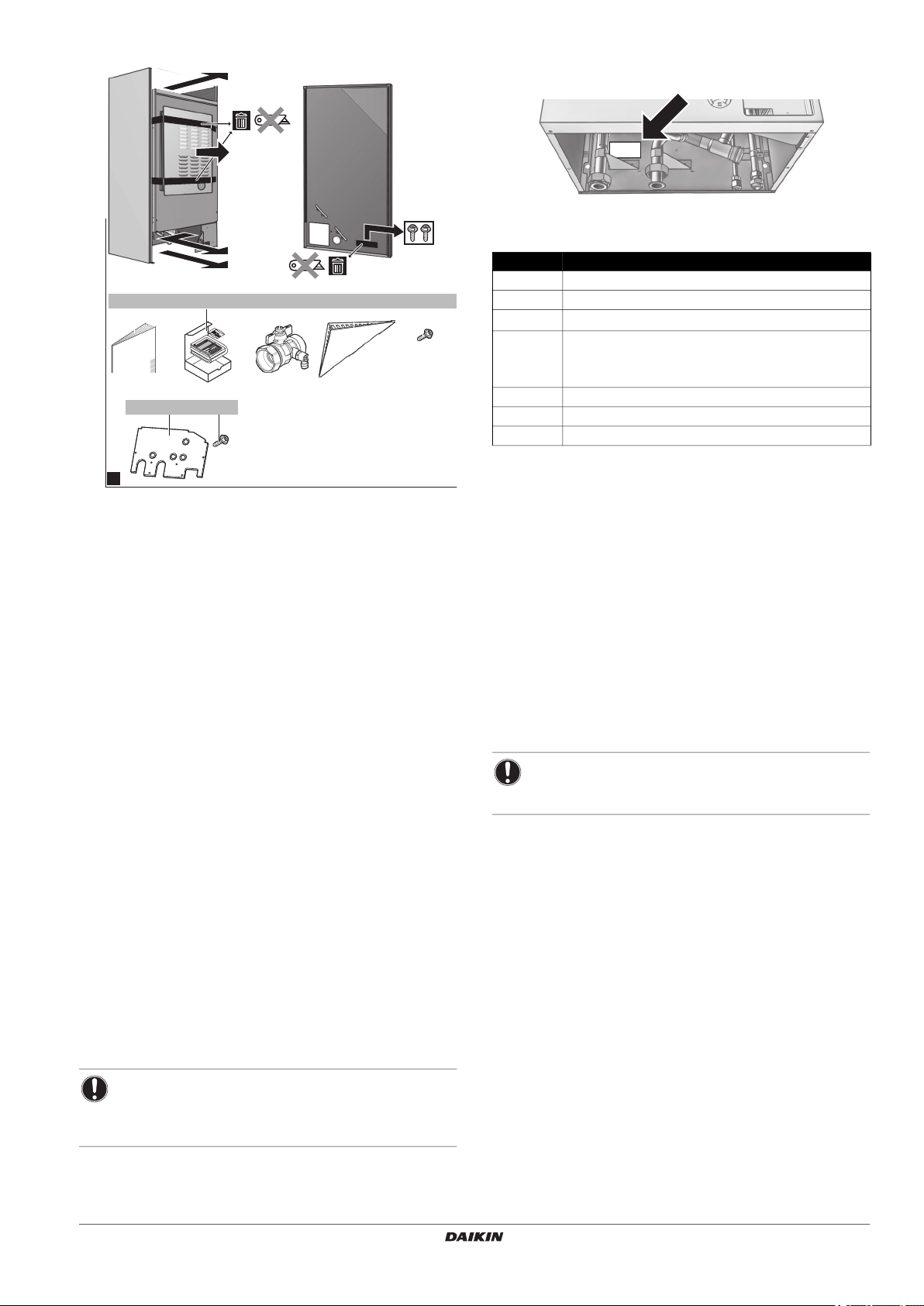
3 Remove the accessories.
d
b
c
h
e
a
1x
bcd
2x 1x
g
4x
f
1x
e
1x
2x
3
4.1.1. Identification label: Indoor unit
Location
Model identification
Modelname: HXY080A8V1B, HXY125A8V1B
Code Description
H Hydro Box
X VRV connection
Y
080 Capacity class (approx.):
A8 Series
V1 Voltage 1 P~, 220-240 V, 50 Hz
B European Market
4.2. Possible combinations of units and options
Reversible applications (cooling + heating)
080 kW x 10 cooling capacity
125 kW x 10 cooling capacity
a HXY(080/125) manual
b User interface kit: user interface, 4 fixing screws, 2 plugs
c Shut-off valve
d User interface cover
e 2 fixing screws front panel
f Bottomplate
g 4 fixing screws bottom plate
h Topplate
4.2.1. List of options for indoor unit
User interface (EKRUAHT)
The user interface is delivered as an accessory with the unit. An
additional user interface is optionally available.
The additional user interface can be connected to have both:
Control close to the indoor unit.
Room thermostat functionality in the principal space to be
heated.
Room thermostat (EKRTWA, EKRTR1)
4. About the units and options
You can connect an optional room thermostat to the indoor unit. This
thermostat can either be wired (EKRTWA) or wireless (EKRTR1).
4.1. General information
For installation instructions, see the installation manual of the room
thermostat.
This installation manual concerns VRV IV indoor unit air to water
inverter heat pump units of the Daikin HXY080/125 series.
These units are intended for indoor installation and aimed for
commercial and public buildings.
The unit is designed for wall mounted installation.
HXY080/125 units have a heating capacity of 9 kW/14 kW, cooling
capacity of 8.2 KW/12.5 kW.
The indoor units are designed to work at indoor ambient
temperatures from 5°C to 30°C.
During heating operation, the unit can heat up water to temperatures
of 25°C to 45°C, cooling operation of 5°C to 20°C.
The units are designed for indoor installation (outdoor temperatures:
cooling 10°C to 43°C, heating: -20°C to 24°C) (for details see
technical data book).
Remote sensor for wireless thermostat (EKRTETS)
You can use a wireless indoor temperature sensor (EKRTETS) only
in combination with the wireless thermostat (EKRTR1).
For installation intructions, see the installation manual of the room
thermostat.
Demand PCB (EKRP1AHTA)
An optional EKRP1AHTA demand PCB can be connected to the
indoor unit. This PCB is needed when an external room thermostat is
installed and provides the communication with the indoor unit.
NOTICE
An additional 230 V AC power supply is required for the
EKRTR1 room thermostat.
Refer to the demand PCB installation manual for further details.
4.1. Identification
NOTICE
When installing or servicing several units at the same time,
make sure NOT to switch the service panels between
different models.
Refer to the wiring diagram or connection diagram for connecting this
PCB to the unit and "7.3.5. To connect the electrical wiring on the
indoor unit" on page 14.
Heat pump convector (FWXV)
An optional FWXV convector for heating/cooling operation can be
connected to this indoor unit.
Refer to the heat pump convector installation manual for further
details.
HXY080+125A8V1BF
VRV IV System indoor unit
4P405267-1C – 2021.04
Installation and operation manual
5

Drain pan kit (EKHBDPCA2)
C
B
A
d
B
A
d
b
e
c
f f
ii
j
a
g
h
The drain pan is required to drain accumulated condensation from
the indoor unit. It is required during low temperature cooling
operation of the indoor unit and when the leaving water temperature
is <18°C.
For installation of this option into the indoor unit, refer to the
installation manual delivered with this option kit.
Heater kit (EKBUH)
The heater kit option can be installed to assist the heat pump during
heating operation or to provide primary heating during emergency
situations
(1)
.
4.2.2. Possible combinations of indoor unit and outdoor unit
Outdoor unit
Indoor unit RYYQ8~20 RYYQ22~54 RXYQ8~20 RXYQ22~54
HXY080A8V1B O X O X
HXY125A8V1B O X O X
O = allowed
X = not allowed
INFORMATION
For detailed information, refer to the VRV IV heat pump
combination table in Technical Data. Combinations are
explained depending on the system layout of the VRV IV
heat pump series.
5. Application guidelines
5.1. Overview: Application guidelines
The purpose of the application guidelines is to give a glance of the
possibilities of the Daikin heat pump system.
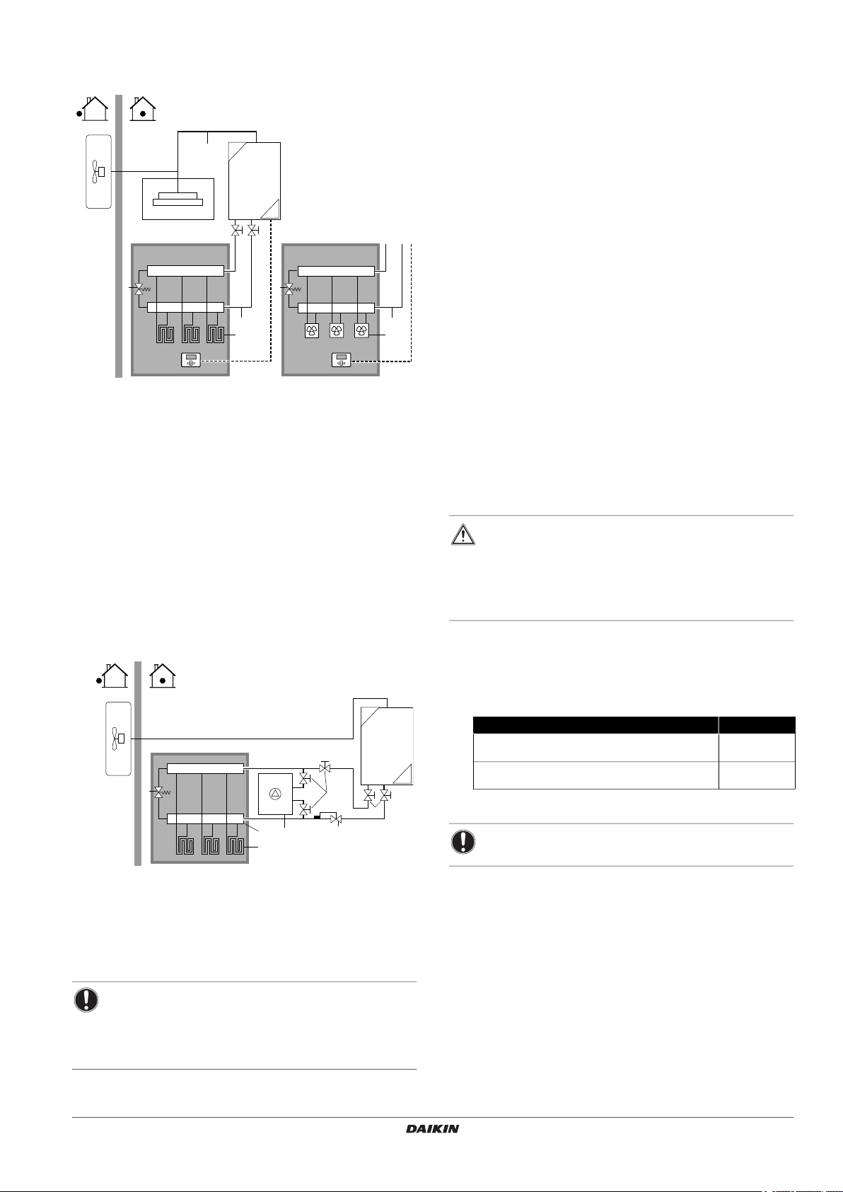
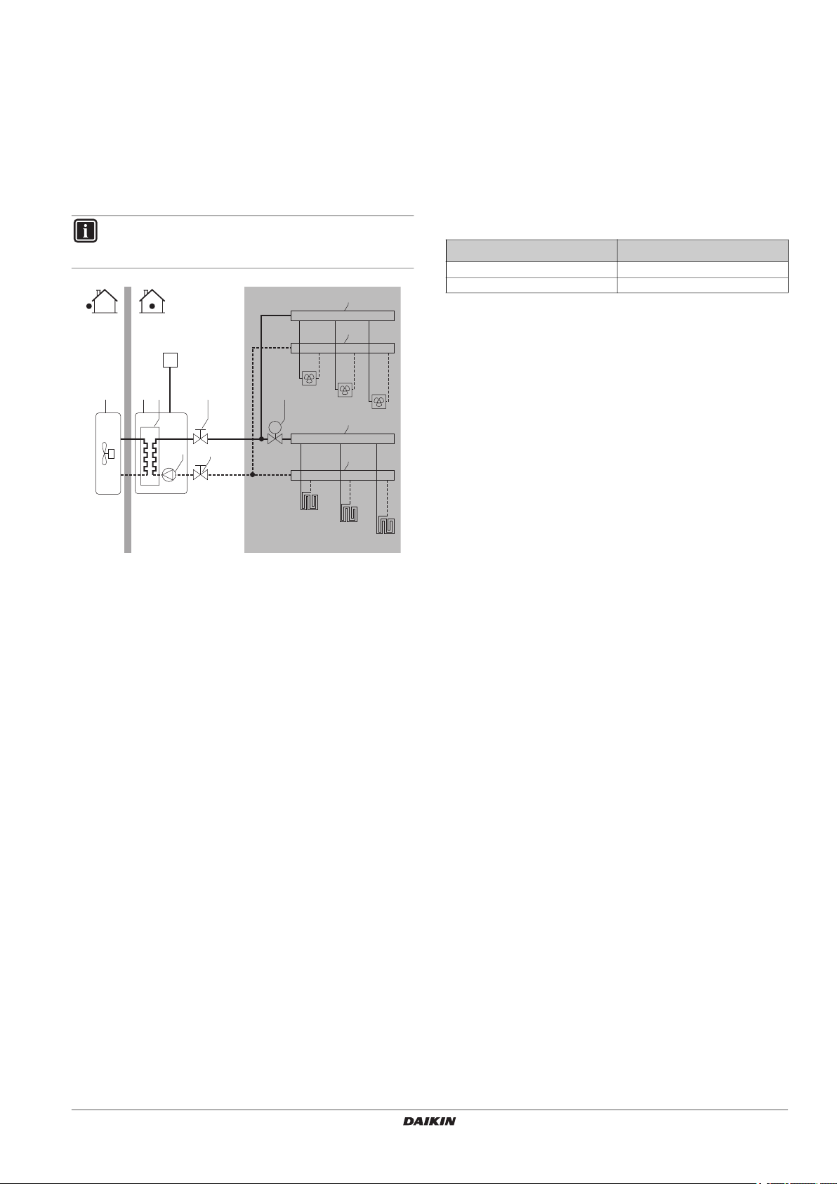
5.2.1. Single room
Under floor heating or heat pump convector – Wired room
thermostat
Setup
A Main leaving water temperature zone
B One single room
C One single room
a Outdoor VRV IV heat pump
b VRV Direct Expansion (DX) Indoor unit cassette
c HXY(080/125)
d Optional EKRUAHT user interface (master)
e Refrigerant piping
f Water piping
g Floor heating loop
h Fan coil unit
i Bypass valve (field supply)
j User interface (slave)
NOTICE
The illustrations in the application guidelines are
meant for reference only, and are NOT to be used as
detailed hydraulic diagrams. The detailed hydraulic
dimensioning and balancing are NOT shown, and are
the responsibility of the installer.
For more information about the configuration settings
to optimize heat pump operation, see the
configuration chapter.
This chapter contains applications guidelines for:
Setting up the space heating/cooling system
Setting up an auxiliary heat source for space heating
5.2. Setting up the space heating/cooling system
The Daikin heat pump system supplies leaving water to heat emitters
in one or more rooms.
Because the system offers a wide flexibility to control the temperature
in each room, you need to answer the following questions first:
How many rooms are heated (or cooled) by the Daikin
heat pump system?
Which heat emitter types are used in each room and what is
their design leaving water temperature?
Once the space heating/cooling requirements are clear, Daikin
recommends to follow the setup guidelines below.
(1) More information can be found in the manual of the heater kit and on page
"9. Installing the optional EKBUHAA(6V3/6W1) heater kit" on page 26 of
this manual.
Installation and operation manual
6
The under floor heating or heat pump connection is directly
connected to the indoor unit.
The room temperature is controlled by the user interface, which
is used as room thermostat. Possible installations:
User interface (standard equipment) installed in the room and
used as room thermostat
User interface (standard equipment) installed at the indoor
unit and used for control close to the indoor unit + user
interface (optional equipment EKRUAHT) installed in the
room and used as room thermostat
Benefits
Cost effective. You do NOT need an additional external room
thermostat.
Highest comfort and efficiency. The smart room thermostat
functionality can decrease or increase the desired leaving water
temperature based on the actual room temperature
(modulation). This results in:
Stable room temperature matching the desired temperature
(higher comfort)
Less ON/OFF cycles (more quiet, higher comfort and higher
efficiency)
Lowest possible leaving water temperature (higher efficiency)
Easy. You can easily set the desired room temperature via the
user interface:
For your daily needs, you can use preset values and
schedules.
To deviate from your daily needs, you can temporarily
overrule the preset values and schedules.
HXY080+125A8V1BF
VRV IV System indoor unit
4P405267-1C – 2021.04
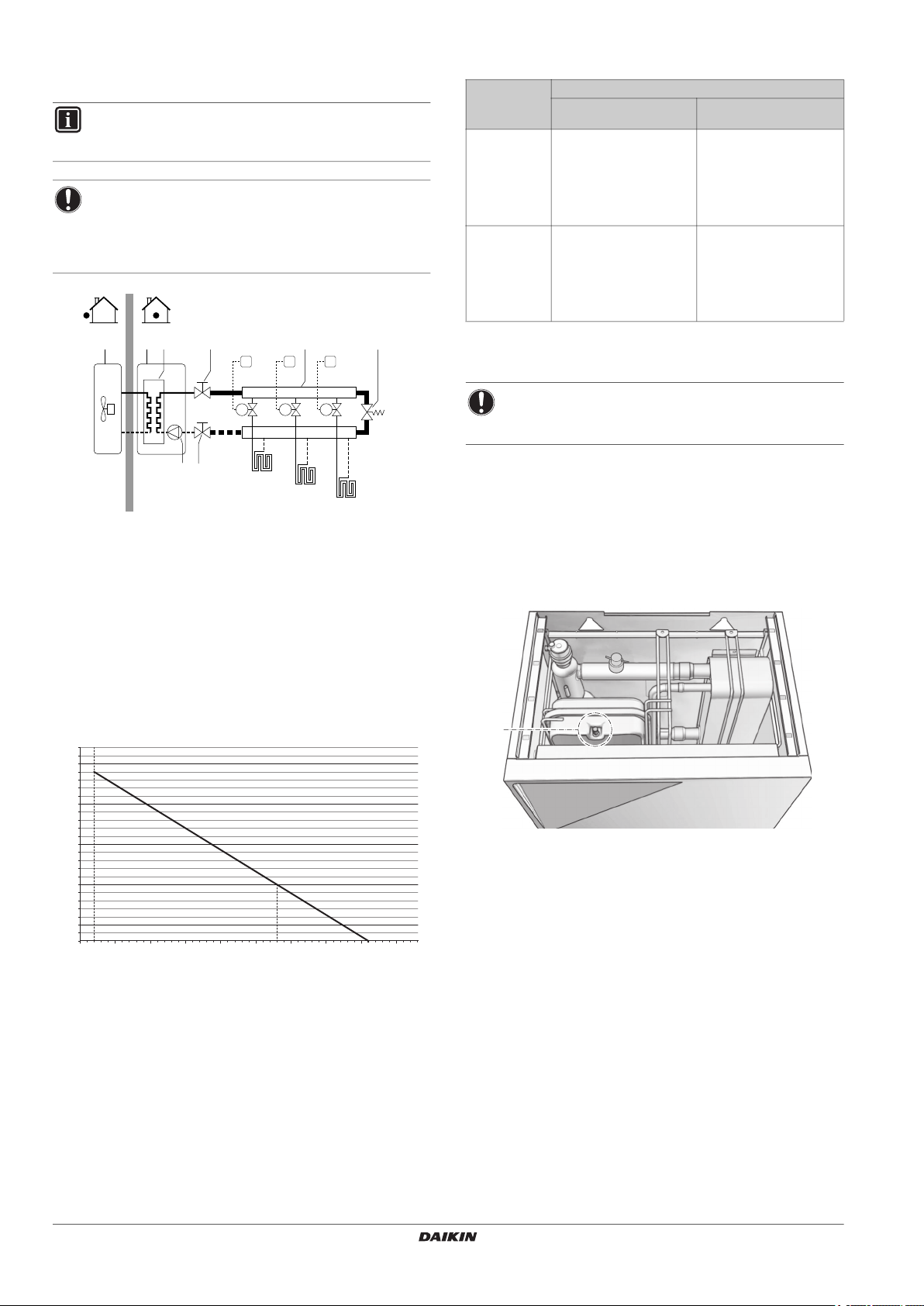
Under floor heating or heat pump convectors – External room
C
B
A
d
B
A
d
b
e
c
f f
ii
a
g
h
g
a
cbd
e
f
e
thermostat
Setup
Make sure the return water to the heat pump does NOT exceed
45°C. To do so:
Set the desired water temperature via the auxiliary boiler
controller to maximum 45°C.
Install an aquastat valve in the return water flow of the
heat pump.
Set the aquastat valve to close above 45°C and to open
below 45°C.
Install non-return valves.
Make sure to only have one expansion vessel in the water
circuit. An expansion vessel is already premounted in the indoor
unit.
Alternative option EKBUH can be considered. The heater kit option
will provide additional capacity in case of heat pump capacity
shortage. See "9. Installing the optional EKBUHAA(6V3/6W1) heater
kit" on page 26 for details.
6. Preparation
A Main leaving water temperature zone
B One single room
C One single room
a Outdoor VRV IV heat pump
b VRV Direct Expansion (DX) Indoor unit cassette
c HXY(080/125)
d External room thermostat
e Refrigerant piping
f Water piping
g Floor heating loop
h Fan coil unit
i Bypass valve (field supply)
The under floor heating or heat pump convectors are directly
connected to the indoor unit.
The room temperature is controlled by the external room
thermostat (demand PCB is needed for this option).
5.3. Using an auxiliary heat source
6.1. Preparing installation site
Do NOT install the unit in places often used as work place. In case of
construction works (e.g. grinding works) where a lot of dust is
created, the unit must be covered.
Choose the installation location with sufficient place for carrying the
unit in and out of the site.
6.1.1. Installation site requirements of the indoor unit
WARNING
Be sure to provide for adequate measures in order to
prevent that the unit is used as a shelter by small animals
Small animals making contact with electrical parts can
cause malfunctions, smoke or fire. Please instruct the
customer to keep the area around the unit clean and clear.
Select an installation site that meets the following requirements:
All piping lengths and distances have been taken into
consideration (for requirements of piping length for the
refrigerant piping, refer to the outdoor unit installation manual):
Mind the measurement guidelines:
Requirement Value
Maximum refrigerant piping length between indoor
unit and outdoor unit.
Maximum height difference between indoor unit and
outdoor unit.
(a) Refer to VRV IV piping lenght restrictions to judge the complete VRV system
integration.
<135 m
<15 m
(a)
(a)
NOTICE
Mind the following spacing installation guidelines.
a Outdoor VRV IV heat pump
b Floor heating loop (field supply)
c Collector (field supply)
d Auxiliary heat source (field supply)
e Shut-off valve
f Aquastat valve (field supply)
g Bypass valve (field supply)
NOTICE
Make sure the auxiliary boiler and its integration in the
system complies with applicable legislation.
Daikin is NOT responsible for incorrect or unsafe
situations in the auxiliary boiler system.
HXY080+125A8V1BF
VRV IV System indoor unit
4P405267-1C – 2021.04
Installation and operation manual
7
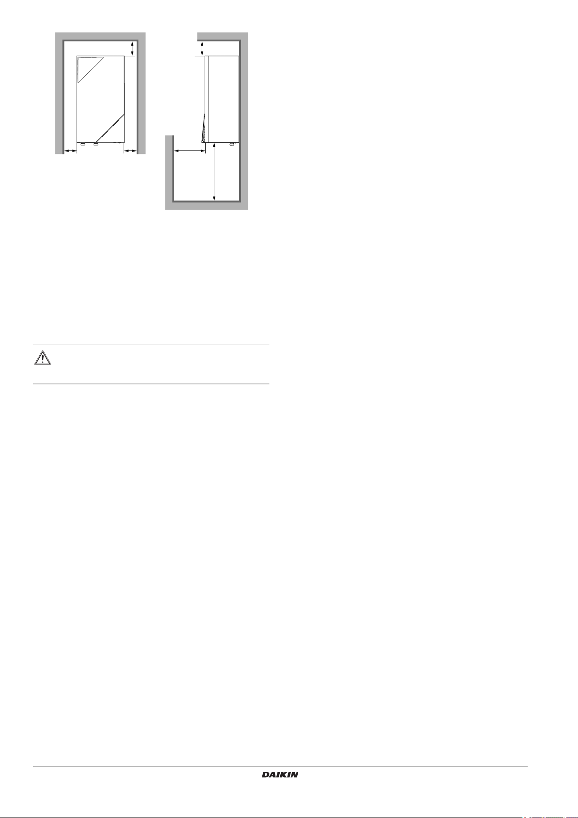
The space around the unit allows for sufficient air circulation.
(mm)
There is no danger of fire due to leakage of inflammable gas.
The equipment is not intended for use in a potentially explosive
atmosphere.
Take care that in the event of a water leak, water cannot cause
any damage to the installation space and surroundings.
Be sure that sufficient precautions are taken, in accordance with
the applicable legislation, in case of refrigerant leakage.
When installing the unit in a small room, take measures in order
to keep the refrigerant concentration from exceeding allowable
safety limits in the event of a refrigerant leak.
WARNING
Excessive refrigerant concentrations in a closed room can
lead to oxygen deficiency.
6.2. Preparing water circuit
6.2.1. Selection of the type of heat emitters
The selection of the heat emitter is the choice of the end customer.
The choice of the heat emitter will define the needed water
temperature from the unit.
Based on the needed water temperature for the heat emitters,
following range can be defined:
1 Low temperature (heating leaving water temperature range from
25°C to 40°C, cooling leaving water temperature range from
25°C to 18°C).
Typical example: floor heating.
2 Medium temperature (leaving water temperature range from
40°C to 45°C), cooling leaving water temperature range from
12°C to 7°C.
Typical example: low temperature radiators (heating) and
convectors (heating and cooling).
Once the heat emitters are chosen, the capacity of these heat
emitters should be defined and from this the dimensioning and
position of the heat emitters in the different rooms should be decided.
An important parameter of the heat emitters is the temperature
difference between entering water and leaving water.
This will define the water flow in the system.
Finally, the piping layout from the heat source to the different heat
emitters needs to be drawn.
This will finally define following important parameters:
Minimal water volume in the system.
Maximal water volume in the system.
Minimal and maximal water flow in system.
Maximal pressure drop in the system.
Do not climb, sit or stand on top of the unit.
Do not place any objects or equipment on top of the unit (top
plate).
Do NOT install the unit in places such as:
Where there is mist of mineral oil, oil spray or vapour.
Plastic parts may deteriorate, and cause them to fall out or water
to leak.
Do NOT install the unit in sound sensitive areas (e.g. near a
bedroom and the like), so that the operation noise will cause no
trouble.
Note: If the sound is measured under actual installation
conditions, the measured value will be higher than the sound
pressure level mentioned in Sound spectrum due to
environmental noise and sound reflections.
The foundation must be strong enough to bear the weight of the
unit.
Make sure, in the event of a water leak, water cannot cause any
damage to the installation space and surroundings.
In places with high humidity (max. RH=85%), for example a
bathroom.
In places where frost is possible. Ambient temperature around
the indoor unit should be >5°C.
The indoor unit is designed for indoor installation only and for
indoor ambient temperatures ranging 5~35°C in cooling mode
and 5~30°C in heating mode.
Installation and operation manual
8
HXY080+125A8V1BF
VRV IV System indoor unit
4P405267-1C – 2021.04
6.2.2. Water circuit requirements
M
T
FCU2
FCU3
FHL1
FHL2
FHL3
abc
d e
ef
g
g
g
g
65°C
Use the indoor unit only in a closed water system.
Using the system in an open water system will lead to excessive
corrosion.
Maximum water temperature is 45°C (heating) and mimimum
water temperature is 5°C (cooling).
The maximum water pressure is 3 bar.
Provide adequate safeguards in the water circuit to ensure that
the maximum pressure is NOT exceeded.
All installed piping and piping accessories (valve,
connections,…) must withstand the following temperatures.
Shut-off valves delivered with the unit should be installed so that
normal servicing can be accomplished without draining the
system.
Make all water piping connections in accordance with the
applicable legislation and the outlook diagram that is delivered
with the unit, respecting the water inlet and outlet.
Do NOT use excessive force when connecting the piping.
Deformation of the piping can cause malfunctioning of the unit.
Provide drain taps at all low points of the system in order to allow
complete drainage of the water circuit.
Provide a proper drain for the pressure relief valve to avoid
water coming into contact with electrical parts.
Provide air vents at all high points of the system, which must
also be easily accessible for servicing. An automatic air purge is
provided in the indoor unit. Check that the air purge is NOT
tightened too much, so that automatic release of air in the water
circuit is possible.
Only use materials that are compatible with water used in the
system and with the materials used in the indoor unit.
Check that all components in the field piping can withstand the
water pressure and water temperature.
When using non-brass metallic piping, insulate the brass and
non-brass properly so that they do NOT make contact with each
other. This to prevent galvanic corrosion.
INFORMATION
The following illustration is an example and may NOT
match your system layout.
a Outdoor unit (VRV IV heat pump)
b Indoor unit HXY(080/125)
c Heat exchanger
d Pump
e Shut-off valve
f Motorised 2-way valve (field supply)
g Collector
FCU1...3 Fan coil unit (optional)
FHL1...3 Floor heating loop (optional)
T Room thermostat (optional)
Never use Zn-coated parts in the water circuit. Because the
unit's internal water circuit uses copper piping, excessive
corrosion may occur.
Only use appropriate tooling to handle brass, which is a soft
material. If NOT, pipes will get damaged.
Select the water piping diameter in relation to the required water
flow and the available external static pressure of the pump. See
"14. Technical Data" on page 40 for the external static pressure
curves of the indoor unit.
You can find the minimum required water flow for the indoor unit
operation in the following table. When the water flow is lower,
flow malfunction A6 will be displayed and the indoor unit will be
stopped.
Model Minimum water flow (l/min)
HXY080A8V1B 15
HXY125A8V1B 15
It is strongly recommended to install an additional filter on the
heating water circuit. Especially to remove metallic particles
from the field heating piping, it is advised to use a magnetic or
cyclone filter, which can remove small particles. Small particles
may damage the unit and will NOT be removed by the standard
filter of the heat pump system.
If air or dust gets into the water circuit, problems may occur. To
prevent this:
Only use clean pipes
Hold the pipe end downwards when removing burrs.
Cover the pipe end when inserting it through a wall, to
prevent dust and/or particles entering the pipe.
Use a decent thread sealant to seal connections.
For safety reasons, it is NOT allowed to add any kind of glycol to
the water circuit.
The installation must be in compliance with the applicable
legislation and may require additional hygienic installation
measures.
In accordance with the applicable legislation, it may be
necessary to install thermostatic mixing valves.
6.2.3. Formula to calculate the expansion vessel pre-pressure
The pre-pressure (Pg) of the vessel depends on the installation
height difference (H):
Pg=0.3+(H/10) (bar)
6.2.4. To check the water volume
The indoor unit has an expansion vessel of 10 litre with a factory set
pre-pressure of 1 bar.
To make sure that the unit operates properly:
You must check the minimum and maximum water volume.
You might need to adjust the pre-pressure of the expansion
vessel.
HXY080+125A8V1BF
VRV IV System indoor unit
4P405267-1C – 2021.04
Installation and operation manual
9
Minimum water volume
FHL1
FHL2
FHL3
M1
T1
M2T2M3
T3
fecba g
de
.3
.5
1
.5
2
.5
10050
0
20
150 200 250 300 350 400 450
b
a
Check that the total water volume in the installation is minimum
20 liter, the internal water volume of the indoor unit NOT included.
INFORMATION
In critical processes, or in rooms with a high heat load,
extra water might be required
NOTICE
When circulation in each space heating loop is controlled
by remotely controlled valves, it is important that the
minimum water volume is guaranteed, even if all of the
valves are closed.
a Outdoor unit (VRV IV heat pump)
b Indoor unit HXY(080/125)
c Heat exchanger
d Pump
e Shut-off valve
f Collector (field supply)
g By-pass valve (field supply)
FHL1...3 Floor heating loop (field supply)
T1...3 Individual room thermostat (optional)
M1...3 Individual motorised valve to control loop FHL1...3
(field supply)
Maximum water volume
Use the following graph to determine the maximum water volume for
the calculated pre-pressure.
a
2
Example: Maximum water volume and expansion vessel prepressure
Installation
height
difference
≤7 m No pre-pressure
>7 m Do the following:
(a) This is the height difference (m) between the highest point of the water circuit and
Water volume
≤ 280 l >280 l
(a)
adjustment is required.
• Increase the
pre-pressure.
• Check if the water
volume does NOT
exceed the maximum
allowed water volume.
the indoor unit. If the indoor unit is at the highest point of the installation, the
installation height is 0 m.
Do the following:
• Decrease the
pre-pressure.
• Check if the water
volume does NOT
exceed the maximum
allowed water volume.
The expansion vessel of
the indoor unit is too small
for the installation.
6.2.5. Changing the pre-pressure of the expansion vessel
NOTICE
Only a licensed installer may adjust the pre-pressure of the
expansion vessel.
When changing the default pre-pressure of the expansion vessel
(1 bar) is required, take following guidelines into account:
Only use dry nitrogen to set the expansion vessel pre-pressure.
Inappropriate setting of the expansion vessel pre-pressure will
lead to malfunction of the system.
Changing the pre-pressure of the expansion vessel should be done
by releasing or increasing nitrogen pressure through the schräder
valve of the expansion vessel.
1
a Schräder valve
6.2.6. To check the water volume: Examples
Example 1
The indoor unit is installed 5 m below the highest point in the water
0
0
a Pre-pressure (bar)
b Maximum water volume (l)
circuit. The total water volume in the water circuit is 100 l.
No actions or adjustments are required.
Example 2
The indoor unit is installed at the highest point in the water circuit.
The total water volume in the water circuit is 350 l.
Actions:
Because the total water volume (350 l) is more than the default
water volume (280 l), the pre-pressure must be decreased.
The required pre-pressure is:
Pg = (0.3+(H/10)) bar = (0.3+(0/10)) bar=0.3 bar.
The corresponding maximum water volume at 0.3 bar is 410 l.
(See the graph in the chapter above).
Because 350 l is lower than 410 l, the expansion vessel is
appropriate for the installation.
Installation and operation manual
10
HXY080+125A8V1BF
VRV IV System indoor unit
4P405267-1C – 2021.04
6.3. Preparing electrical wiring
5
8
0
1
5
0
0
0
a
b
1
6
b
a
e
f
d
c
10
11
8
2
3
4
5
9
17
g
h
14
12
13
6.3.1. About preparing electrical wiring
WARNING
Establish proper earthing. Do NOT earth the unit to a
utility pipe, surge absorber, or telephone earth.
Incomplete earthing may cause electrical shock.
Install the required fuses or circuit breakers.
Secure the electrical wiring with cable ties so that the
cables do NOT come in contact with the piping or
sharp edges, particularly on the high-pressure side
Do NOT use taped wires, stranded conductor wires,
extension cords, or connections from a star system.
They can cause overheating, electrical shock or fire.
All wiring must be performed by an authorized
electrician and must comply with the applicable
legislation.
Make electrical connections to the fixed wiring.
All components procured on the site and all electrical
construction must comply with the applicable
legislation.
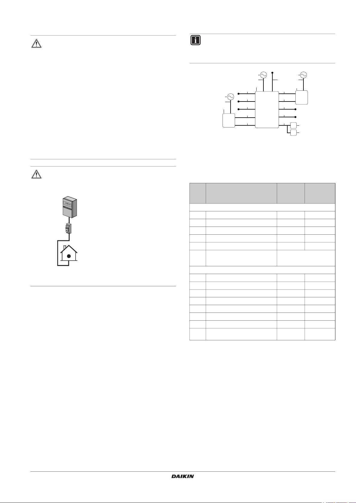
WARNING
The indoor unit should have a dedicated power
supply.
a Normal power supply
b Fuse
1 Power supply for indoor unit
The optional heater kit (EKBUH) should have a
dedicated power supply.
6.3.2. Overview of electrical connections on the indoor unit
The following illustration shows the required field wiring.
INFORMATION
The following illustration is an example and may NOT
match your system layout.
For details see "14.2. Wiring diagram" on page 41.
a Dedicated power supply for the indoor unit
b HXY(080/125)
c User interface
d Optional user interface
e Optional heater kit
f Dedicated power supply for the external backup heater kit
g Optional room thermostat
h 230 V AC power supply
Maximum
running
Item Description Wiring
High voltage wiring (High voltage bundle)
1 Indoor unit power supply 2+GND
2 malfunction output 2 0.3 A
3 Operation ON/OFF output 2 0.3 A
4 Cooling/heating output 2 0.3 A
5 Heater kit step 1/2 output 3
6 External heater kit power supply For details refer to the
Low voltage wiring (Low voltage bundle)
7 Indoor/outdoor transmission 2
8 User interface transmission 2
9 External heater kit safety 2
10 Thermostat input 1 2
11 Thermostat input 2 2
12 Operation ON signal 2
13 Operation OFF signal 2
14 230 V AC power supply (only for
wireless room thermostat EKRTR1)
(a) Refer to name plate on the indoor unit.
(b) Minimum cable section 0.75 mm².
(c) Cable section between 0.75 mm² and 1.25 mm².
installation manual provided
with the option kit.
2 <1 A
current
(a)
(b)
(b)
(b)
(b)
(c)
(c)
(b)
(b)
(b)
(b)
(b)
HXY080+125A8V1BF
VRV IV System indoor unit
4P405267-1C – 2021.04
Installation and operation manual
11
7. Installation
60kg
1
2
4x
1
2
3
3
2x
43 5 6
87
2x
9
2x
10
11
1
2
2
2
4x
12 13
b
a
Before installing, first read the instructions of previous chapter.
INFORMATION
Installation shall be done by an installer, the choice of
materials and installation shall comply with the applicable
legislation. In Europe the EN378 is the applicable standard
that shall be used.
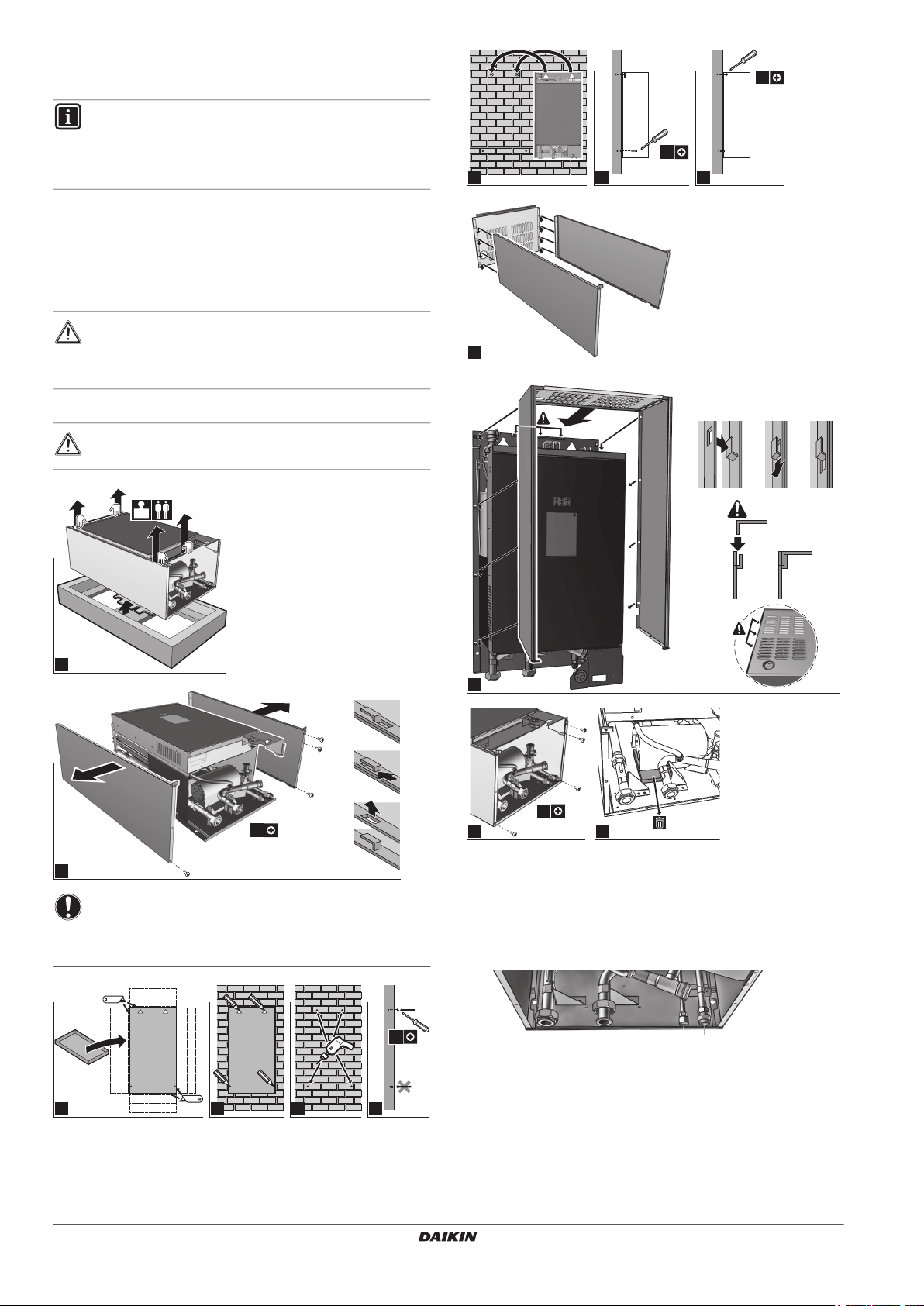
7.1. Mounting the indoor unit
7.1.1. To install the indoor unit
1 Remove the accessories from the unit, see instructions in
chapter "3.1.2. To remove the accessories from the indoor unit"
on page 4.
WARNING
Tear apart and throw away plastic packaging bags so that
children will not play with them. Children playing with
plastic bags face danger of death by suffocation.
2 Install indoor unit as follows.
CAUTION
Do NOT grasp the piping to lift the indoor unit.
NOTICE
Please install following the spacing installation guidelines
as described in "6.1.1. Installation site requirements of the
indoor unit" on page 7.
Installation and operation manual
12
7.1.2. To install the drainpan kit
If a drain pan kit (EKHBDPCA2) is required, install it before
connecting the refrigerant and water pipes and the electrical wiring.
To install, see the installation manual of the drain pan kit.
7.1.3. To connect the refrigerant piping to the outdoor unit
a Refrigerant liquid connection Ø9.52 mm
b Refrigerant gas connection Ø15.9 mm
1 Connect the liquid piping from the outdoor unit to the refrigerant
liquid connection of the indoor unit.
2 Connect the gas piping from the outdoor unit to the refrigerant
gas connection of the indoor unit.
HXY080+125A8V1BF
VRV IV System indoor unit
4P405267-1C – 2021.04
For details concerning vacuuming and operating the unit during
ab
1 2
4x
3
vacuuming, see installation manual of outdoor unit.
For details concerning piping sizes and refnet selection, see
installation manual of the outdoor unit.
NOTICE
Do NOT put power on the unit before vacuuming is
completed. In case this happened, refer to the instructions
in the installation manual of the outdoor unit to avoid dirt,
air or nitrogen to be trapped in the piping.
7.2. Connecting the water piping
7.2.1. To connect the water piping
NOTICE
Do NOT use excessive force when connecting the piping.
Deformation of the piping can cause malfunctioning of the
unit.
To facilitate service and maintenance, 2 shut-off valves are provided.
Mount the valves on the water inlet and on the water outlet. Mind their
position. Orientation of the integrated drain valves is important for
servicing.
1 Install the shut-off valves on the water pipes.
a Water inlet
b Water outlet
2 Screw the indoor unit nuts on the shut-off valves.
3 Connect the field piping on the shut-off valves.
NOTICE
It is recommended to install a pressure reducing valve on
the cold water inlet in accordance with the applicable
legislation.
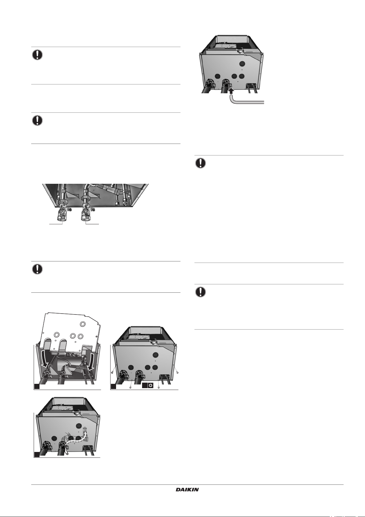
7.2.2. To install the bottom plate and connect safety valve
drain hose
7.2.3. To fill the water circuit
1 Connect the water supply hose to the drain and fill valve.
2 Open the drain and fill valve.
3 Make sure that the automatic air purge valve is open (at least 2
turns).
4 Fill the circuit with water until the manometer indicates a
pressure of ±2.0 bar.
5 Purge as much air as possible from the water circuit.
NOTICE
Air in the water circuit can cause malfunctioning of the
flow switch. During filling, it may not be possible to
remove all the air from the circuit. Remaining air will
be removed through the automatic air purge valves
during the initial operating hours of the system.
Additional filling with water afterwards may be
required.
Pump only operation in order to purge the air of the
system is possible through field settings. Refer to field
settings of [E-04] in the chapter "[E] Service mode" on
page 21 for further details.
The unit might dispose some excessive water through
the pressure relief valve.
Water quality must be accordingly to EU directive
98/83 EC.
6 Close the drain and fill valve.
7 Disconnect the water supply hose from the drain and fill valve.
NOTICE
The water pressure needle on the manometer will vary
depending on the water temperature (higher pressure at
higher water temperature).
However, at all times water pressure shall remain above
1 bar to avoid air entering the circuit.
HXY080+125A8V1BF
VRV IV System indoor unit
4P405267-1C – 2021.04
7.2.4. To insulate the water piping
The piping in the complete water circuit must be insulated to prevent
condensation during cooling operation and reduce capacity losses
during heating and cooling operations.
If the temperature is higher than 30°C and the humidity is higher than
RH 80%, the thickness of the sealing materials should be at least
20 mm to prevent condensation on the surface of the sealing.
Installation and operation manual
13
 Loading...