

Daikin HXHD125AV1B, HXHD200AY1B Installation manuals
INSTALLATION MANUAL
system indoor unit
HXHD125A
HXHD200AY1B
V1B
ATITIKTIES-DEKLARACIJA
ATBILSTĪBAS-DEKLARĀCIJA
VYHLÁSENIE-ZHODY
CE -
CE -
CE -
CE - UYUMLULUK-BİLDİRİSİ
ZJAVA O SKLADNOSTI
VASTAVUSDEKLARATSIOON
ДЕКЛАРАЦИЯ-ЗА-СЪОТВЕТСТВИЕ
CE - I
CE -
CE -
deklaruje na własną wyłączną odpowiedzialność, że urządzenia, których ta deklaracja dotyczy:
z vso odgovornostjo izjavlja, da je oprema naprav, na katero se izjava nanaša:
kinnitab oma täielikul vastutusel, et käesoleva deklaratsiooni alla kuuluv varustus:
declară pe proprie răspundere că echipamentele la care se referă această declaraţie:
декларира на своя отговорност, че оборудването, за което се отнася тази декларация:
m
o
x
r
17
IZJAVA-O-USKLAĐENOSTI
DEKLARACJA-ZGODNOŚCI
DECLARAŢIE-DE-CONFORMITATE
CE - MEGFELELŐSÉGI-NYILATKOZAT
CE -
CE -
CE -
b
18
19
20
21
PROHLÁŠENÍ-O-SHODĚ
CE - ERKLÆRING OM-SAMSVAR
CE - ILMOITUS-YHDENMUKAISUUDESTA
CE -
Direktive z vsemi spremembami.
Direktiivid koos muudatustega.
Директиви, с техните изменения.
Direktyvose su papildymais.
Direktīvās un to papildinājumos.
Smernice, v platnom znení.
19
20
Direktiver, med senere ændringer.11Direktiv, med företagna ändringar.12Direktiver, med foretatte endringer.13Direktiivejä, sellaisina kuin ne ovat muutettuina.
10
visiška savo atsakomybe skelbia, kad įranga, kuriai taikoma ši deklaracija:
ar pilnu atbildību apliecina, ka tālāk aprakstītās iekārtas, uz kurām attiecas šī deklarācija:
vyhlasuje na vlastnú zodpovednosť, že zariadenie, na ktoré sa vzťahuje toto vyhlásenie:
tamamen kendi sorumluluğunda olmak üzere bu bildirinin ilgili olduğu donanımının aşağıdaki gibi olduğunu beyan eder:
t
v
k
w
22
23
24
25
megfelelnek az alábbi szabvány(ok)nak vagy egyéb irányadó dokumentum(ok)nak, ha azokat előírás szerint használják:
spełniają wymogi następujących norm i innych dokumentów normalizacyjnych, pod warunkiem że używane są zgodnie z naszymi
instrukcjami:
sunt în conformitate cu următorul (următoarele) standard(e) sau alt(e) document(e) normativ(e), cu condiţia ca acestea să fie utilizate în
conformitate cu instrucţiunile noastre
skladni z naslednjimi standardi in drugimi normativi, pod pogojem, da se uporabljajo v skladu z našimi navodili:
on vastavuses järgmis(t)e standardi(te)ga või teiste normatiivsete dokumentidega, kui neid kasutatakse vastavalt meie juhenditele:21съответстват на следните стандарти или други нормативни документи, при условие, че се използват съгласно нашите
инструкции:22atitinka žemiau nurodytus standartus ir (arba) kitus norminius dokumentus su sąlyga, kad yra naudojami pagal mūsų nurodymus:
tad, ja lietoti atbilstoši ražotāja norādījumiem, atbilst sekojošiem standartiem un citiem normatīviem dokumentiem:
sú v zhode s nasledovnou(ými) normou(ami) alebo iným(i) normatívnym(i) dokumentom(ami), za predpokladu, že sa používajú v súlade
s našim návodom:
16
17
18
19
20
ürünün, talimatlarımıza göre kullanılması koşuluyla aşağıdaki standartlar ve norm belirten belgelerle uyumludur:
23
24
25
Directives, as amended.
Direktiven, gemäß Änderung.03Directives, telles que modifiées.04Richtlijnen, zoals geamendeerd.
01
02
Değiştirilmiş halleriyle Yönetmelikler.
21
22
23
24
25
v platném znění.
Smjernice, kako je izmijenjeno.
14
15
Directivas, según lo enmendado.
Direttive, come da modifica.07√‰ËÁÈÒv, fiˆ˜ ¤¯Ô˘Ó ÙÚÔÔÔÈËı›.
05
06
*
**
и оценено
irányelv(ek) és módosításaik rendelkezéseit.
z późniejszymi poprawkami.
Directivelor, cu amendamentele respective.
съгласно
<A>
16
17
Directivas, conforme alteração em.
08
.
18
<B>
положително от
както е изложено в
Cертификата <C>
21 Забележка *
Директив со всеми поправками.
09
, pozytywną opinią
igazolta a megfelelést,
<A>
<B>
szerint.
alapján, a(z)
<A>
<C> tanúsítvány
a(z)
zgodnie z dokumentacją
a(z)
16 Megjegyzés *
17 Uwaga *
Machinery 2006/42/EC
enligt
<B>
og gjennom positiv
<A>
.
Electromagnetic Compatibility 2014/30/EU
och godkänts av
<A>
enligt
Certifikatet <C>
som det fremkommer i
<A> DAIKIN.TCF.025H7/03-2015
<B> DEKRA (NB0344)
<C> 2082543.0551-QUA/EMC
v
<B>
<B>
.
pozitīvajam
<C> Sertifikasına
<B>
.
a pozitívne zistené
sertifikātu <C>
.
<A>
ir kaip teigiamai nuspręsta
un atbilstoši
<A>
<A>
Sertifikatą <C>
pagal
kaip nustatyta
kā norādīts
22 Pastaba *
23 Piezīmes *
.
şi apreciat pozitiv
Certificatul <C>
.
<A>
în conformitate cu
Świadectwem <C>
i
<B>
<B>
aşa cum este stabilit în
de
Notă *
18
on
.
<B>
ja jotka
mukaisesti.
<A>
Sertifikat <C>
ifølge
<B>
Sertifikaatin <C>
bedømmelse av
hyväksynyt
jotka on esitetty asiakirjassa
tarafından olumlu olarak
<B>
osvedčením <C>
‘da belirtildiği gibi ve
vērtējumam saskaņā ar
súlade s
ako bolo uvedené v
<A>
göre
değerlendirildiği gibi.
*
Not
24 Poznámka *
25
v
.
<B>
ja heaks
<A>
sertifikaadile <C>
.
in odobreno s strani
<A>
järgi vastavalt
certifikatom <C>
<B>
skladu s
kiidetud
kot je določeno v
nagu on näidatud dokumendis
*
19 Opomba *
20 Märkus
v
<B>
.
.
a pozitivně zjištěno
i pozitivno ocijenjeno od
<A>
Certifikatu <C>
<A>
prema
osvědčením <C>
<B>
strane
jak bylo uvedeno v
kako je izloženo u
souladu s
Daikin Europe N.V. je pooblaščen za sestavo datoteke s tehnično mapo.
Daikin Europe N.V. on volitatud koostama tehnilist dokumentatsiooni.
Daikin Europe N.V. е оторизирана да състави Акта за техническа конструкция.
Daikin Europe N.V. yra įgaliota sudaryti šį techninės konstrukcijos failą.
Daikin Europe N.V. ir autorizēts sastādīt tehnisko dokumentāciju.
Spoločnosť Daikin Europe N.V. je oprávnená vytvoriť súbor technickej konštrukcie.
**
**
19
20
Daikin Europe N.V. on valtuutettu laatimaan Teknisen asiakirjan.
Společnost Daikin Europe N.V. má oprávnění ke kompilaci souboru technické konstrukce.
**
**
13
14
Daikin Europe N.V. Teknik Yapı Dosyasını derlemeye yetkilidir.
**
**
**
**
**
21
22
23
24
25
Daikin Europe N.V. je ovlašten za izradu Datoteke o tehničkoj konstrukciji.
A Daikin Europe N.V. jogosult a műszaki konstrukciós dokumentáció összeállítására.
Daikin Europe N.V. ma upoważnienie do zbierania i opracowywania dokumentacji konstrukcyjnej.
Daikin Europe N.V. este autorizat să compileze Dosarul tehnic de construcţie.
**
**
**
**
15
16
17
18
заявляет, исключительно под свою ответственность, что обор удование, к которому относится настоящее заявление:
erklærer som eneansvarlig, at udstyret, som er omfattet af denne erklæring:
deklarerar i egenskap av huvudansvarig, att utrustningen som berörs av denna deklaration innebär att:
erklærer et fullstendig ansvar for at det utstyr som berøres av denne deklarasjon, innebærer at:
ilmoittaa yksinomaan omalla vastuullaan, että tämän ilmoituksen tarkoittamat laitteet:
prohlašuje ve své plné odpovědnosti, že zařízení, k němuž se toto prohlášení vztahuje:
izjavljuje pod isključivo vlastitom odgovornošću da oprema na koju se ova izjava odnosi:
teljes felelőssége tudatában kijelenti, hogy a berendezések, melyekre e nyilatkozat vonatkozik:
u
q
s
n
j
c
y
09
10
11
12
CE - DECLARAÇÃO-DE-CONFORMIDADE
СЕ - ЗАЯВЛЕНИЕ-О-СООТВЕТСТВИИ
CE - OPFYLDELSESERKLÆRING
CE - FÖRSÄKRAN-OM-ÖVERENSTÄMMELSE
CE - ¢H§ø™H ™YMMOPºø™H™
CE - DECLARACION-DE-CONFORMIDAD
CE - DICHIARAZIONE-DI-CONFORMITA
declares under its sole responsibility that the equipment to which this declaration relates:
erklärt auf seine alleinige Verantwortung, dass die Ausrüstung für die diese Erklärung bestimmt ist:
déclare sous sa seule responsabilité que l’équipement visé par la présente déclaration:
verklaart hierbij op eigen exclusieve verantwoordelijkheid dat de apparatuur waarop deze verklaring betrekking heeft:
a
d
f
l
CE - DECLARATION-OF-CONFORMITY
CE - KONFORMITÄTSERKLÄRUNG
CE - DECLARATION-DE-CONFORMITE
CE - CONFORMITEITSVERKLARING
Daikin Europe N.V.
01
02
03
04
h
13
14
15
16
la declaración:
referencia
declara bajo su única responsabilidad que el equipo al que hace
dichiara sotto la propria responsabilità che gli apparecchi a cui è riferita questa dichiarazione:
declara sob sua exclusiva responsabilidade que os equipamentos a que esta declaração se refere:
‰ЛПТУВИ МВ ·ФОПВИЫЩИО‹ ЩЛ˜ В˘ı‡УЛ fiЩИ Ф ВНФПИЫМfi˜ ЫЩФУ ФФ›Ф ·У·К¤ЪВЩ·И Л ·ЪФ‡Ы· ‰‹ПˆЫЛ:
e
i
p
g
05
06
07
08
HXHD125A8V1B,
estão em conformidade com a(s) seguinte(s) norma(s) ou outro(s) documento(s) normativo(s), desde que estes sejam utilizados de
acordo com as nossas instruções:09соответствуют следующим стандартам или другим нормативным документам, при условии их использования согласно нашим
инструкциям:10overholder følgende standard(er) eller andet/andre retningsgivende dokument(er), forudsat at disse anvendes i henhold til vore
instrukser:11respektive utrustning är utförd i överensstämmelse med och följer följande standard(er) eller andra normgivande dokument, under
förutsättning att användning sker i överensstämmelse med våra instruktioner:12respektive utstyr er i overensstemmelse med følgende standard(er) eller andre normgivende dokument(er), under forutssetning av at
disse brukes i henhold til våre instrukser:13vastaavat seuraavien standardien ja muiden ohjeellisten dokumenttien vaatimuksia edellyttäen, että niitä käytetään ohjeidemme
mukaisesti:14za předpokladu, že jsou využívány v souladu s našimi pokyny, odpovídají následujícím normám nebo normativním dokumentům:
08
are in conformity with the following standard(s) or other normative document(s), provided that these are used in accordance with our
instructions:02der/den folgenden Norm(en) oder einem anderen Normdokument oder -dokumenten entspricht/entsprechen, unter der Voraussetzung,
daß sie gemäß unseren Anweisungen eingesetzt werden:03sont conformes à la/aux norme(s) ou autre(s) document(s) nor matif(s), pour autant qu'ils soient utilisés conformément à nos instructions:04conform de volgende norm(en) of één of meer andere bindende documenten zijn, op voorwaarde dat ze worden gebruikt overeenkomstig
01
onze instructies:05están en conformidad con la(s) siguiente(s) norma(s) u otro(s) documento(s) nor mativo(s), siempre que sean utilizados de acuerdo con
nuestras instrucciones:06sono conformi al(i) seguente(i) standard(s) o altro(i) documento(i) a carattere normativo, a patto che vengano usati in conformità alle
u skladu sa slijedećim standardom(ima) ili drugim normativnim dokumentom(ima), uz uvjet da se oni koriste u skladu s našim uputama:
15
nostre istruzioni:07В›У·И Ы‡МКˆУ· МВ ЩФ(·) ·ОfiПФ˘ıФ(·) ЪfiЩ˘Ф(·) ‹ ¿ППФ ¤ББЪ·КФ(·) О·УФУИЫМТУ, ˘fi ЩЛУ ЪФ¸fiıВЫЛ fiЩИ ¯ЪЛЫИМФФИФ‡УЩ·И
Û‡Ìʈӷ Ì ÙȘ Ô‰ËÁ›Â˜ Ì·˜:
EN60335-2-40,
11 Information *
12 Merk *
.
Î·È ÎÚ›ÓÂÙ·È ıÂÙÈο
<A>
Certificato <C>
e giudicato positivamente
<A>
ob upoštevanju določb:
vastavalt nõuetele:
следвайки клаузите на:
laikantis nuostatų, pateikiamų:
ievērojot prasības, kas noteiktas:
održiavajúc ustanovenia:
19
20
under iagttagelse af bestemmelserne i:11enligt villkoren i:
10
following the provisions of:02gemäß den Vorschriften der:03conformément aux stipulations des:
01
bunun koşullarına uygun olarak:
21
22
23
24
25
gitt i henhold til bestemmelsene i:
noudattaen määräyksiä:
za dodržení ustanovení předpisu:
prema odredbama:
követi a(z):17zgodnie z postanowieniami Dyrektyw:
12
13
14
15
16
overeenkomstig de bepalingen van:05siguiendo las disposiciones de:
secondo le prescrizioni per:07Ì ًÚËÛË Ùˆv ‰È·Ù¿Íˆv Ùˆv:
04
06
secondo il
<B>
delineato nel
da
* fiˆ˜ ηıÔÚ›˙ÂÙ·È ÛÙÔ
™ËÌ›ˆÛË
06 Nota *
07
<B>
positiv
<B>
.
în urma prevederilor:
18
<C>
Certificate
and judged positively by
aufgeführt und von
<A>
<A>
according to the
as set out in
wie in der
de acordo com o previsto em:09в соответствии с положениями:
08
01 Note *
02 Hinweis *
13 Huom *
14 Poznámka *
.
¶ИЫЩФФИЛЩИОfi <C>
Û‡Ìʈӷ Ì ÙÔ
<B>
·fi ÙÔ
.
<C>
Zertifikat
beurteilt gemäß
15 Napomena *
.
i
<B>
Certificado <C>
согласно
e com o parecer
<B>
<A>
de acordo com o
<B>
tal como estabelecido em
positivo de
*
08 Nota
.
et évalué positivement par
Certificat <C>
<A>
conformément au
tel que défini dans
<B>
03 Remarque *
.
.
и в соответствии с
og positivt vurderet af
<A>
<A>
Certifikat <C>
henhold til
положительным решением
как указано в
Свидетельству <C>
som anført i
09 Примечание *
10 Bemærk *
.
y es valorado
de acuerdo con el
<A>
Certificaat <C>
en positief beoordeeld door
<B>
<A>
.
overeenkomstig
positivamente por
zoals vermeld in
<B>
como se establece en
Certificado <C>
*
04 Bemerk *
05 Nota
Shigeki Morita
Director
Ostend, 1st of April 2016
∏ Daikin Europe N.V. Â›Ó·È ÂÍÔ˘ÛÈÔ‰ÔÙË̤ÓË Ó· Û˘ÓÙ¿ÍÂÈ ÙÔÓ ∆¯ÓÈÎfi Ê¿ÎÂÏÔ Î·Ù·Û΢‹˜.
A Daikin Europe N.V. está autorizada a compilar a documentação técnica de f abrico.
Компания Daikin Europe N.V. уполномочена составить Комплект технической документации.
Daikin Europe N.V. er autoriseret til at udarbejde de tekniske konstruktionsdata.
Daikin Europe N.V. är bemyndigade att sammanställa den tekniska konstruktionsfilen.
**
07
Daikin Europe N.V. is authorised to compile the Technical Construction File.
**
01
Daikin Europe N.V. har tillatelse til å kompilere den Tekniske konstruksjonsfilen.
**
**
**
**
**
08
09
10
11
12
Daikin Europe N.V. hat die Berechtigung die Technische Konstruktionsakte zusammenzustellen.
Daikin Europe N.V. est autorisé à compiler le Dossier de Constr uction Technique.
Daikin Europe N.V. is bevoegd om het Technisch Constr uctiedossier samen te stellen.
Daikin Europe N.V. está autorizado a compilar el Archivo de Construcción Técnica.
Daikin Europe N.V. è autorizzata a redigere il File Tecnico di Costruzione.
**
**
**
**
**
05
06
3P402254-5A
02
03
04

ATITIKTIES-DEKLARACIJA
ATBILSTĪBAS-DEKLARĀCIJA
VYHLÁSENIE-ZHODY
CE -
CE -
CE -
CE - UYUMLULUK-BİLDİRİSİ
ZJAVA O SKLADNOSTI
VASTAVUSDEKLARATSIOON
ДЕКЛАРАЦИЯ-ЗА-СЪОТВЕТСТВИЕ
CE - I
CE -
CE -
deklaruje na własną wyłączną odpowiedzialność, że urządzenia, których ta deklaracja dotyczy:
z vso odgovornostjo izjavlja, da je oprema naprav, na katero se izjava nanaša:
kinnitab oma täielikul vastutusel, et käesoleva deklaratsiooni alla kuuluv varustus:
declară pe proprie răspundere că echipamentele la care se referă această declaraţie:
декларира на своя отговорност, че оборудването, за което се отнася тази декларация:
m
o
x
r
b
18
20
21
19
17
IZJAVA-O-USKLAĐENOSTI
DEKLARACJA-ZGODNOŚCI
DECLARAŢIE-DE-CONFORMITATE
CE - MEGFELELŐSÉGI-NYILATKOZAT
CE -
CE -
CE -
Direktive z vsemi spremembami.
Direktiivid koos muudatustega.
Директиви, с техните изменения.
Direktyvose su papildymais.
Direktīvās un to papildinājumos.
Smernice, v platnom znení.
19
20
Direktiver, med senere ændringer.11Direktiv, med företagna ändringar.12Direktiver, med foretatte endringer.13Direktiivejä, sellaisina kuin ne ovat muutettuina.
10
visiška savo atsakomybe skelbia, kad įranga, kuriai taikoma ši deklaracija:
ar pilnu atbildību apliecina, ka tālāk aprakstītās iekārtas, uz kurām attiecas šī deklarācija:
vyhlasuje na vlastnú zodpovednosť, že zariadenie, na ktoré sa vzťahuje toto vyhlásenie:
tamamen kendi sorumluluğunda olmak üzere bu bildirinin ilgili olduğu donanımının aşağıdaki gibi olduğunu beyan eder:
t
v
k
w
23
24
25
22
megfelelnek az alábbi szabvány(ok)nak vagy egyéb irányadó dokumentum(ok)nak, ha azokat előírás szerint használják:
spełniają wymogi następujących norm i innych dokumentów normalizacyjnych, pod warunkiem że używane są zgodnie z naszymi
instrukcjami:
sunt în conformitate cu următorul (următoarele) standard(e) sau alt(e) document(e) normativ(e), cu condiţia ca acestea să fie utilizate în
conformitate cu instrucţiunile noastre
skladni z naslednjimi standardi in drugimi normativi, pod pogojem, da se uporabljajo v skladu z našimi navodili:
on vastavuses järgmis(t)e standardi(te)ga või teiste normatiivsete dokumentidega, kui neid kasutatakse vastavalt meie juhenditele:21съответстват на следните стандарти или други нормативни документи, при условие, че се използват съгласно нашите
инструкции:22atitinka žemiau nurodytus standartus ir (arba) kitus norminius dokumentus su sąlyga, kad yra naudojami pagal mūsų nurodymus:
tad, ja lietoti atbilstoši ražotāja norādījumiem, atbilst sekojošiem standartiem un citiem normatīviem dokumentiem:
sú v zhode s nasledovnou(ými) normou(ami) alebo iným(i) normatívnym(i) dokumentom(ami), za predpokladu, že sa používajú v súlade
s našim návodom:
16
17
18
19
20
ürünün, talimatlarımıza göre kullanılması koşuluyla aşağıdaki standartlar ve norm belirten belgelerle uyumludur:
23
24
25
Directives, as amended.
Direktiven, gemäß Änderung.03Directives, telles que modifiées.04Richtlijnen, zoals geamendeerd.
01
02
Değiştirilmiş halleriyle Yönetmelikler.
21
22
23
24
25
v platném znění.
Smjernice, kako je izmijenjeno.
irányelv(ek) és módosításaik rendelkezéseit.
z późniejszymi poprawkami.
Directivelor, cu amendamentele respective.
14
15
16
17
18
положително от <B> съгласно
Cертификата <C>.
21 Забележка * както е изложено в <A> и оценено
Directivas, según lo enmendado.
Direttive, come da modifica.07√‰ËÁÈÒv, fiˆ˜ ¤¯Ô˘Ó ÙÚÔÔÔÈËı›.
Directivas, conforme alteração em.
Директив со всеми поправками.
05
06
08
09
*
**
a(z) <C> tanúsítvány szerint.
pagal Sertifikatą <C>.
22 Pastaba * kaip nustatyta <A> ir kaip teigiamai nuspręsta <B>
<B> i Świadectwem <C>.
<A> DAIKIN.TCF.025J1/02-2018
<B> DEKRA (NB0344)
súlade s osvedčením <C>.
vērtējumam saskaņā ar sertifikātu <C>.
24 Poznámka * ako bolo uvedené v <A> a pozitívne zistené <B> v
23 Piezīmes * kā norādīts <A> un atbilstoši <B> pozitīvajam
skladu s certifikatom <C>.
de <B> în conformitate cu Certificatul <C>.
<C> 2082543.0551-QUA/EMC
Daikin Europe N.V. je pooblaščen za sestavo datoteke s tehnično mapo.
Daikin Europe N.V. on volitatud koostama tehnilist dokumentatsiooni.
Daikin Europe N.V. е оторизирана да състави Акта за техническа конструкция.
Daikin Europe N.V. yra įgaliota sudaryti šį techninės konstrukcijos failą.
Daikin Europe N.V. ir autorizēts sastādīt tehnisko dokumentāciju.
Spoločnosť Daikin Europe N.V. je oprávnená vytvoriť súbor technickej konštrukcie.
**
21
**
22
**
23
**
24
Daikin Europe N.V. Teknik Yapı Dosyasını derlemeye yetkilidir.
**
25
**
19
<A>‘da belirtildiği gibi ve <C> Sertifikasına
göre <B> tarafından olumlu olarak
değerlendirildiği gibi.
*
Not
25
kiidetud <B> järgi vastavalt sertifikaadile <C>.
**
20
PROHLÁŠENÍ-O-SHODĚ
CE - ERKLÆRING OM-SAMSVAR
CE - ILMOITUS-YHDENMUKAISUUDESTA
CE -
заявляет, исключительно под свою ответственность, что обор удование, к которому относится настоящее заявление:
erklærer som eneansvarlig, at udstyret, som er omfattet af denne erklæring:
deklarerar i egenskap av huvudansvarig, att utrustningen som berörs av denna deklaration innebär att:
erklærer et fullstendig ansvar for at det utstyr som berøres av denne deklarasjon, innebærer at:
ilmoittaa yksinomaan omalla vastuullaan, että tämän ilmoituksen tarkoittamat laitteet:
prohlašuje ve své plné odpovědnosti, že zařízení, k němuž se toto prohlášení vztahuje:
izjavljuje pod isključivo vlastitom odgovornošću da oprema na koju se ova izjava odnosi:
teljes felelőssége tudatában kijelenti, hogy a berendezések, melyekre e nyilatkozat vonatkozik:
u
q
s
n
j
c
y
09
10
11
12
CE - DECLARAÇÃO-DE-CONFORMIDADE
СЕ - ЗАЯВЛЕНИЕ-О-СООТВЕТСТВИИ
CE - OPFYLDELSESERKLÆRING
CE - FÖRSÄKRAN-OM-ÖVERENSTÄMMELSE
13
14
la declaración:
referencia
h
15
16
estão em conformidade com a(s) seguinte(s) norma(s) ou outro(s) documento(s) normativo(s), desde que estes sejam utilizados de
acordo com as nossas instruções:09соответствуют следующим стандартам или другим нормативным документам, при условии их использования согласно нашим
инструкциям:10overholder følgende standard(er) eller andet/andre retningsgivende dokument(er), forudsat at disse anvendes i henhold til vore
instrukser:11respektive utrustning är utförd i överensstämmelse med och följer följande standard(er) eller andra normgivande dokument, under
förutsättning att användning sker i överensstämmelse med våra instruktioner:12respektive utstyr er i overensstemmelse med følgende standard(er) eller andre normgivende dokument(er), under forutssetning av at
disse brukes i henhold til våre instrukser:13vastaavat seuraavien standardien ja muiden ohjeellisten dokumenttien vaatimuksia edellyttäen, että niitä käytetään ohjeidemme
mukaisesti:14za předpokladu, že jsou využívány v souladu s našimi pokyny, odpovídají následujícím normám nebo normativním dokumentům:
08
u skladu sa slijedećim standardom(ima) ili drugim normativnim dokumentom(ima), uz uvjet da se oni koriste u skladu s našim uputama:
15
Machinery 2006/42/EC
Low Voltage 2014/35/EU
Electromagnetic Compatibility 2014/30/EU
19 ob upoštevanju določb:
20 vastavalt nõuetele:
21 следвайки клаузите на:
22 laikantis nuostatų, pateikiamų:
23 ievērojot prasības, kas noteiktas:
24 održiavajúc ustanovenia:
25 bunun koşullarına uygun olarak:
17 Uwaga * zgodnie z dokumentacją <A>, pozytywną opinią
18 Notă * aşa cum este stabilit în <A> şi apreciat pozitiv
16 Megjegyzés * a(z) <A> alapján, a(z) <B> igazolta a megfelelést,
Certifikatet <C>.
11 Information * enligt <A> och godkänts av <B> enligt
da <B> secondo il Certificato <C>.
06 Nota * delineato nel <A> e giudicato positivamente
19 Opomba * kot je določeno v <A> in odobreno s strani <B> v
bedømmelse av <B> ifølge Sertifikat <C>.
hyväksynyt Sertifikaatin <C> mukaisesti.
souladu s osvědčením <C>.
14 Poznámka * jak bylo uvedeno v <A> a pozitivně zjištěno <B> v
12 Merk * som det fremkommer i <A> og gjennom positiv
13 Huom * jotka on esitetty asiakirjassa <A> ja jotka <B> on
positivo de <B> de acordo com o Certificado <C>.
положительным решением <B> согласно
·fi ÙÔ <B> Û‡Ìʈӷ Ì ÙÔ ¶ИЫЩФФИЛЩИОfi <C>.
09 Примечание * как указано в <A> и в соответствии с
07 ™ËÌ›ˆÛË * fiˆ˜ ηıÔÚ›˙ÂÙ·È ÛÙÔ <A> Î·È ÎÚ›ÓÂÙ·È ıÂÙÈο
08 Nota * tal como estabelecido em <A> e com o parecer
Daikin Europe N.V. on valtuutettu laatimaan Teknisen asiakirjan.
Společnost Daikin Europe N.V. má oprávnění ke kompilaci souboru technické konstrukce.
Daikin Europe N.V. je ovlašten za izradu Datoteke o tehničkoj konstrukciji.
A Daikin Europe N.V. jogosult a műszaki konstrukciós dokumentáció összeállítására.
**
**
**
20 Märkus * nagu on näidatud dokumendis <A> ja heaks
strane <B> prema Certifikatu <C>.
15 Napomena * kako je izloženo u <A> i pozitivno ocijenjeno od
Свидетельству <C>.
henhold til Certifikat <C>.
10 Bemærk * som anført i <A> og positivt vurderet af <B> i
**
14
15
16
13
∏ Daikin Europe N.V. Â›Ó·È ÂÍÔ˘ÛÈÔ‰ÔÙË̤ÓË Ó· Û˘ÓÙ¿ÍÂÈ ÙÔÓ ∆¯ÓÈÎfi Ê¿ÎÂÏÔ Î·Ù·Û΢‹˜.
A Daikin Europe N.V. está autorizada a compilar a documentação técnica de f abrico.
Компания Daikin Europe N.V. уполномочена составить Комплект технической документации.
Daikin Europe N.V. er autoriseret til at udarbejde de tekniske konstruktionsdata.
**
**
**
**
08
07
09
10
Daikin Europe N.V. ma upoważnienie do zbierania i opracowywania dokumentacji konstrukcyjnej.
Daikin Europe N.V. este autorizat să compileze Dosarul tehnic de construcţie.
**
**
17
18
Shigeki Morita
Director
Ostend, 1st of March 2018
Daikin Europe N.V. är bemyndigade att sammanställa den tekniska konstruktionsfilen.
Daikin Europe N.V. har tillatelse til å kompilere den Tekniske konstruksjonsfilen.
**
**
11
12
CE - ¢H§ø™H ™YMMOPºø™H™
CE - DECLARACION-DE-CONFORMIDAD
CE - DICHIARAZIONE-DI-CONFORMITA
declares under its sole responsibility that the equipment to which this declaration relates:
erklärt auf seine alleinige Verantwortung, dass die Ausrüstung für die diese Erklärung bestimmt ist:
déclare sous sa seule responsabilité que l’équipement visé par la présente déclaration:
verklaart hierbij op eigen exclusieve verantwoordelijkheid dat de apparatuur waarop deze verklaring betrekking heeft:
declara bajo su única responsabilidad que el equipo al que hace
dichiara sotto la propria responsabilità che gli apparecchi a cui è riferita questa dichiarazione:
‰ЛПТУВИ МВ ·ФОПВИЫЩИО‹ ЩЛ˜ В˘ı‡УЛ fiЩИ Ф ВНФПИЫМfi˜ ЫЩФУ ФФ›Ф ·У·К¤ЪВЩ·И Л ·ЪФ‡Ы· ‰‹ПˆЫЛ:
a
d
f
l
e
i
CE - DECLARATION-OF-CONFORMITY
CE - KONFORMITÄTSERKLÄRUNG
CE - DECLARATION-DE-CONFORMITE
CE - CONFORMITEITSVERKLARING
Daikin Europe N.V.
01
02
03
g
04
05
07
06
declara sob sua exclusiva responsabilidade que os equipamentos a que esta declaração se refere:
p
08
HXHD200A8Y1B*,
* = , , 1, 2, 3, ..., 9
are in conformity with the following standard(s) or other normative document(s), provided that these are used in accordance with our
instructions:02der/den folgenden Norm(en) oder einem anderen Normdokument oder -dokumenten entspricht/entsprechen, unter der Voraussetzung,
daß sie gemäß unseren Anweisungen eingesetzt werden:03sont conformes à la/aux norme(s) ou autre(s) document(s) nor matif(s), pour autant qu'ils soient utilisés conformément à nos instructions:04conform de volgende norm(en) of één of meer andere bindende documenten zijn, op voorwaarde dat ze worden gebruikt overeenkomstig
01
onze instructies:05están en conformidad con la(s) siguiente(s) norma(s) u otro(s) documento(s) nor mativo(s), siempre que sean utilizados de acuerdo con
nuestras instrucciones:06sono conformi al(i) seguente(i) standard(s) o altro(i) documento(i) a carattere normativo, a patto che vengano usati in conformità alle
under iagttagelse af bestemmelserne i:11enligt villkoren i:
10
nostre istruzioni:07В›У·И Ы‡МКˆУ· МВ ЩФ(·) ·ОfiПФ˘ıФ(·) ЪfiЩ˘Ф(·) ‹ ¿ППФ ¤ББЪ·КФ(·) О·УФУИЫМТУ, ˘fi ЩЛУ ЪФ¸fiıВЫЛ fiЩИ ¯ЪЛЫИМФФИФ‡УЩ·И
Û‡Ìʈӷ Ì ÙȘ Ô‰ËÁ›Â˜ Ì·˜:
following the provisions of:02gemäß den Vorschriften der:03conformément aux stipulations des:
01
EN60335-2-40,
12 gitt i henhold til bestemmelsene i:
13 noudattaen määräyksiä:
14 za dodržení ustanovení předpisu:
15 prema odredbama:
16 követi a(z):
17 zgodnie z postanowieniami Dyrektyw:
18 în urma prevederilor:
according to the Certificate <C>.
beurteilt gemäß Zertifikat <C>.
overeenkomstig de bepalingen van:05siguiendo las disposiciones de:
secondo le prescrizioni per:07Ì ًÚËÛË Ùˆv ‰È·Ù¿Íˆv Ùˆv:
de acordo com o previsto em:09в соответствии с положениями:
04
06
08
01 Note * as set out in <A> and judged positively by <B>
02 Hinweis * wie in der <A> aufgeführt und von <B> positiv
<B> overeenkomstig Certificaat <C>.
<B> conformément au Certificat <C>.
positivamente por <B> de acuerdo con el
Certificado <C>.
05 Nota * como se establece en <A> y es valorado
03 Remarque * tel que défini dans <A> et évalué positivement par
04 Bemerk * zoals vermeld in <A> en positief beoordeeld door
Daikin Europe N.V. is authorised to compile the Technical Construction File.
Daikin Europe N.V. hat die Berechtigung die Technische Konstruktionsakte zusammenzustellen.
Daikin Europe N.V. est autorisé à compiler le Dossier de Constr uction Technique.
Daikin Europe N.V. is bevoegd om het Technisch Constr uctiedossier samen te stellen.
Daikin Europe N.V. está autorizado a compilar el Archivo de Construcción Técnica.
**
02
**
03
**
04
**
05
Daikin Europe N.V. è autorizzata a redigere il File Tecnico di Costruzione.
**
06
3P402254-10E
**
01
HXHD125AV1B
HXHD200AY1B
VRV IV system indoor unit
Installation manual
CONTENTS Page
1. Definitions.................................................................................. 2
1.1. Meaning of warnings and symbols................................................. 2
1.2. Meaning of used terms ..................................................................2
2. General Safety precautions....................................................... 2
3. Introduction................................................................................ 3
3.1. General information........................................................................ 3
3.2. Combination and options............................................................... 3
3.3. Scope of the manual...................................................................... 3
3.4. Model identification........................................................................ 3
4. Accessories ............................................................................... 4
4.1. Accessories supplied with this unit ................................................4
5. Overview of unit......................................................................... 4
5.1. Opening the unit............................................................................. 4
5.2. Main components in the HXHD125 unit......................................... 5
5.3. Main components in the HXHD200 unit......................................... 6
5.4. Functional diagram for the HXHD125 unit ..................................... 7
5.5. Functional diagram for the HXHD200 unit ..................................... 8
5.6. Switch box main components for the HXHD125 unit ..................... 8
5.7. Switch box main components for the HXHD200 unit ..................... 8
6. Design of the water circuit ......................................................... 9
6.1. Selection of the type of heat emitters............................................. 9
6.2. General precautions concerning water circuit................................ 9
6.3. Application examples ................................................................... 10
Floor heating without domestic hot water tank............................. 10
Radiator with domestic hot water tank ......................................... 10
Fan coils without domestic hot water tank ................................... 11
Application example with several heat emitters ........................... 11
7. Installation of the unit............................................................... 12
7.1. Selecting an installation location.................................................. 12
General precautions on installation location ................................ 12
7.2. Dimensions and service space.................................................... 13
Dimensions of unit ....................................................................... 13
Service space of the unit.............................................................. 15
7.3. Inspecting, handling and unpacking the unit ................................ 15
7.4. Installing the unit.......................................................................... 15
Preparation before installation on final installation place ............. 15
Installation on final installation position........................................ 17
Connecting the water circuit......................................................... 17
Fix the indoor unit refrigerant connections................................... 18
Close the unit ............................................................................... 18
7.5. Leak test and vacuuming drying R410A circuit............................ 19
7.6. Water piping ................................................................................. 19
Checking the water volume and expansion
vessel pre-pressure...................................................................... 19
Setting the pre-pressure of the expansion vessel........................ 20
Charging water............................................................................. 21
8. Electrical wiring work............................................................... 21
8.1. Precautions on electrical wiring work........................................... 21
8.2. Internal wiring – Parts table .........................................................22
8.3. System overview of field wiring .................................................... 23
8.4. Requirements............................................................................... 23
8.5. Routing......................................................................................... 24
8.6. Connection................................................................................... 24
Installation and connection of the remote controller .................... 25
Connection to a benefit kWh rate power supply........................... 25
9. Start-up and configuration ....................................................... 27
9.1. Pre-operation checks ................................................................... 27
9.2. Final air purging........................................................................... 27
9.3. Field settings................................................................................ 27
9.4. Procedure ....................................................................................28
9.5. Detailed description .....................................................................28
9.6. Simultaneous demand of space heating and domestic water
heating ......................................................................................... 35
9.7. Multiple set point control.............................................................. 39
9.8. Field setting table ......................................................................... 41
10. Final check and test run .......................................................... 43
10.1. Final check................................................................................... 43
Multi tenant power supply check.................................................. 43
10.2. System test run............................................................................ 43
10.3. Indoor unit individual test run....................................................... 43
Temperature read-out mode......................................................... 43
Procedure for space heating........................................................ 43
Procedure for domestic water heating ......................................... 44
11. Maintenance and service......................................................... 44
11.1. Maintenance activities.................................................................. 44
Checks ......................................................................................... 45
11.2. Vacuuming/recovery and maintenance on refrigerant side .......... 46
System overview.......................................................................... 47
Recovery/vacuuming overview for 1 indoor unit maintenance
(R410A circuit connections) ......................................................... 47
12. Troubleshooting........................................................................ 47
12.1. General guidelines....................................................................... 47
12.2. Opening the unit........................................................................... 47
12.3. Draining the system ..................................................................... 48
12.4. General symptoms....................................................................... 48
12.5. Error codes .................................................................................. 49
13. Unit specifications.................................................................... 50
Technical specifications ............................................................... 50
Electrical specifications: power supply......................................... 50
Electrical specifications: multi tenant power supply (only for
HXHD125).................................................................................... 50
Thank you for purchasing this product.
The original instructions are written in English. All other languages
are translations of the original instructions.
CAREFULLY READ THESE INSTRUCTIONS BEFORE
INSTALLATION. THEY WILL TELL YOU HOW TO INSTALL
AND HOW TO CONFIGURE THE UNIT PROPERLY.
KEEP THIS MANUAL IN A HANDY PLACE FOR FUTURE
REFERENCE.
Installation manual
1
HXHD125AV1B + HXHD200AY1B
VRV IV system indoor unit
4P513552-1 – 2017.11
1. DEFINITIONS
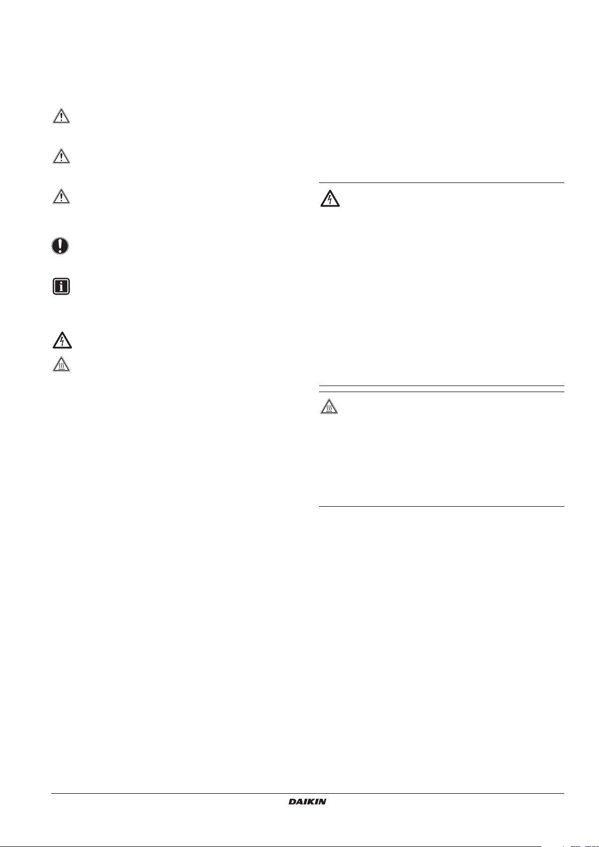
1.1. Meaning of warnings and symbols
Warnings in this manual are classified according to their severity and
probability of occurrence.
DANGER
Indicates an imminently hazardous situation which, if not
avoided, will result in death or serious injury.
WARNING
Indicates a potentially hazardous situation which, if not
avoided, could result in death or serious injury.
CAUTION
Indicates a potentially hazardous situation which, if not
avoided, may result in minor or moderate injury. It may also
be used to alert against unsafe practices.
NOTICE
Indicates situations that may result in equipment or
property-damage accidents only.
INFORMATION
This symbol identifies useful tips or additional information.
Some types of danger are represented by special symbols:
Electric current.
Danger of burning and scalding.
1.2. Meaning of used terms
Installation manual:
Instruction manual specified for a certain product or application,
explaining how to install, configure and maintain it.
Operation manual:
Instruction manual specified for a certain product or application,
explaining how to operate it.
Maintenance instructions:
Instruction manual specified for a certain product or application,
which explains (if relevant) how to install, configure, operate and/or
maintain the product or application.
Dealer:
Sales distributor for products as per the subject of this manual.
Installer:
Technical skilled person who is qualified to install products as per the
subject of this manual.
User:
Person who is owner of the product and/or operates the product.
Service company:
Qualified company which can perform or coordinate the required
service to the unit.
Applicable legislation:
All international, European, national and local directives, laws,
regulations and/or codes which are relevant and applicable for a
certain product or domain.
Accessories:
Equipment which is delivered with the unit and which needs to be
installed according to instructions in the documentation.
Optional equipment:
Equipment which can optionally be combined to the products as per
the subject of this manual.
Field supply:
Equipment which needs to be installed according to instructions in
this manual, but which are not supplied by Daikin.
2. GENERAL SAFETY PRECAUTIONS
The precautions listed here are divided into the following four types.
They all cover very important topics, so be sure to follow them
carefully.
DANGER: ELECTRICAL SHOCK
Switch off all power supply before removing the switchbox
service panel or before making any connections or
touching electrical parts.
Do not touch any switch with wet fingers. Touching a switch
with wet fingers can cause electrical shock. Before
touching electrical parts, turn off all applicable power
supply.
To avoid electric shock, be sure to disconnect the power
supply 1 minute or more before servicing the electrical
parts. Even after 1 minute, always measure the voltage at
the terminals of main circuit capacitors or electrical parts
and, before touching, be sure that those voltages are
50 V DC or less.
When service panels are removed, live parts can easily be
touched by accident. Never leave the unit unattended
during installation or servicing when the service panel is
removed.
DANGER: DO NOT TOUCH PIPING AND INTERNAL
PA RT S
Do not touch the refrigerant piping, water piping or internal
parts during and immediately after operation. The piping
and internal parts may be hot or cold depending on the
working condition of the unit.
Your hand may suffer burns or frostbite if you touch the
piping or internal parts. To avoid injury, give the piping and
internal parts time to return to normal temperature or, if
you must touch them, be sure to wear protective gloves.
HXHD125AV1B + HXHD200AY1B
VRV IV system indoor unit
4P513552-1 – 2017.11
Installation manual
2
3. INTRODUCTION
3.1. General information
This installation manual concerns VRV IV indoor unit air to water
inverter heat pump units of the Daikin HXHD series.
These units are intended for indoor installation and aimed for
commercial and public buildings.
The unit is designed for floor standing heating operation.
HXHD125 units have a heating capacity of 14 kW and HXHD200
units have a heating capacity of 22.4 kW.
The indoor units are designed to work in heating mode at indoor
ambient temperatures from 5°C to 30°C.
During heating operation, the unit can heat up the water to
temperatures of 25°C to 80°C.
3.2. Combination and options
Digital I/O PCB (option)
An optional EKRP1HBAA digital I/O PCB can be connected to the
indoor unit and be used to remotely monitor your system. This
address card offers 2 voltage free outputs and 1 high voltage
(230 V AC) output.
Refer to the operation manual of the indoor unit and to the digital I/O
PCB installation manual for more information.
Refer to the wiring diagram or connection diagram for connecting this
PCB to the unit.
Demand PCB (option)
An optional EKRP1AHTA demand PCB can be connected to the
indoor unit. This PCB is needed when Daikin room thermostat
EKRTR or EKRTW is installed or when multiple set point control is
used, and provides the communication with the indoor unit.
Refer to the demand PCB installation manual for further details.
Refer to the wiring diagram or connection diagram for connecting this
PCB to the unit.
The HXHD units can only be combined with an outdoor REYQ*T or
RWEYQ*T9 unit.
During heating operation, the unit can be combined with space
heating radiators (field supply), fan coil units (option or field supply) or
floor heating (field supply).
The remote controller with room thermostat functionality is standard
supplied with this unit to control your installation.
Domestic hot water tank (option)
An optional EKHTS(U)200AC or EKHTS(U)260AC domestic hot
water tank can be connected to the indoor unit. The domestic hot
water tank has a water volume of 200 l or 260 l.
Refer to the domestic hot water tank installation manual for further
details.
NOTICE
In case there is no instruction in the EKHTS(U)*AC
installation manual on how to connect the domestic hot
water tank to the HXHD unit, please follow the same
instruction as explained for the connection of the domestic
hot water tank to the EKHVMRD unit.
Heat pump convector (option)
An optional FWXV convector for heating operation can be connected
to this indoor unit.
Refer to the heat pump convector installation manual for further
details.
Remote controller (option)
An optional secondary EKRUAHT remote controller (with room
thermostat functionality) can be connected to the indoor unit.
Purpose is to provide the possibility to install the standard remote
controller near the unit (for service reasons), and install another
remote controller in another place (e.g. living room) to operate your
installation.
Refer to "Installation and connection of the remote controller" on
page 25 for further details.
Room thermostat (option)
An optional room thermostat EKRTR or EKRTW can be connected to
the indoor unit.
Refer to the room thermostat installation manual for further details.
3.3. Scope of the manual
This manual does NOT include the selection procedure and the water
system design procedure. Only some precautions and tips and tricks
about the design of the water circuit are given in a separate chapter
of this manual.
Once the selection is done and the water system is designed, this
manual describes the procedures for handling, installing and
connecting the HXHD unit. This manual has been prepared to ensure
adequate maintenance of the unit, and it will provide help if problems
occur.
INFORMATION
Refer to the installation manual of the outdoor unit for items
not described in this manual.
The operation of the indoor unit is described in the indoor
unit operation manual.
3.4. Model identification
H X H D 125 A7 V1 B
For European market
V1=1N~, 220-240 V, 50 Hz
Y1=3N~, 380-415 V, 50 Hz
Series
Identification of the unit capacity
Refrigerant R134a
High temperature floorstanding
Inverter
Hydro box
INFORMATION
If this option is installed it is not possible to use the remote
controller thermostat function.
Installation manual
3
HXHD125AV1B + HXHD200AY1B
VRV IV system indoor unit
4P513552-1 – 2017.11
4. ACCESSORIES
1
5. OVERVIEW OF UNIT
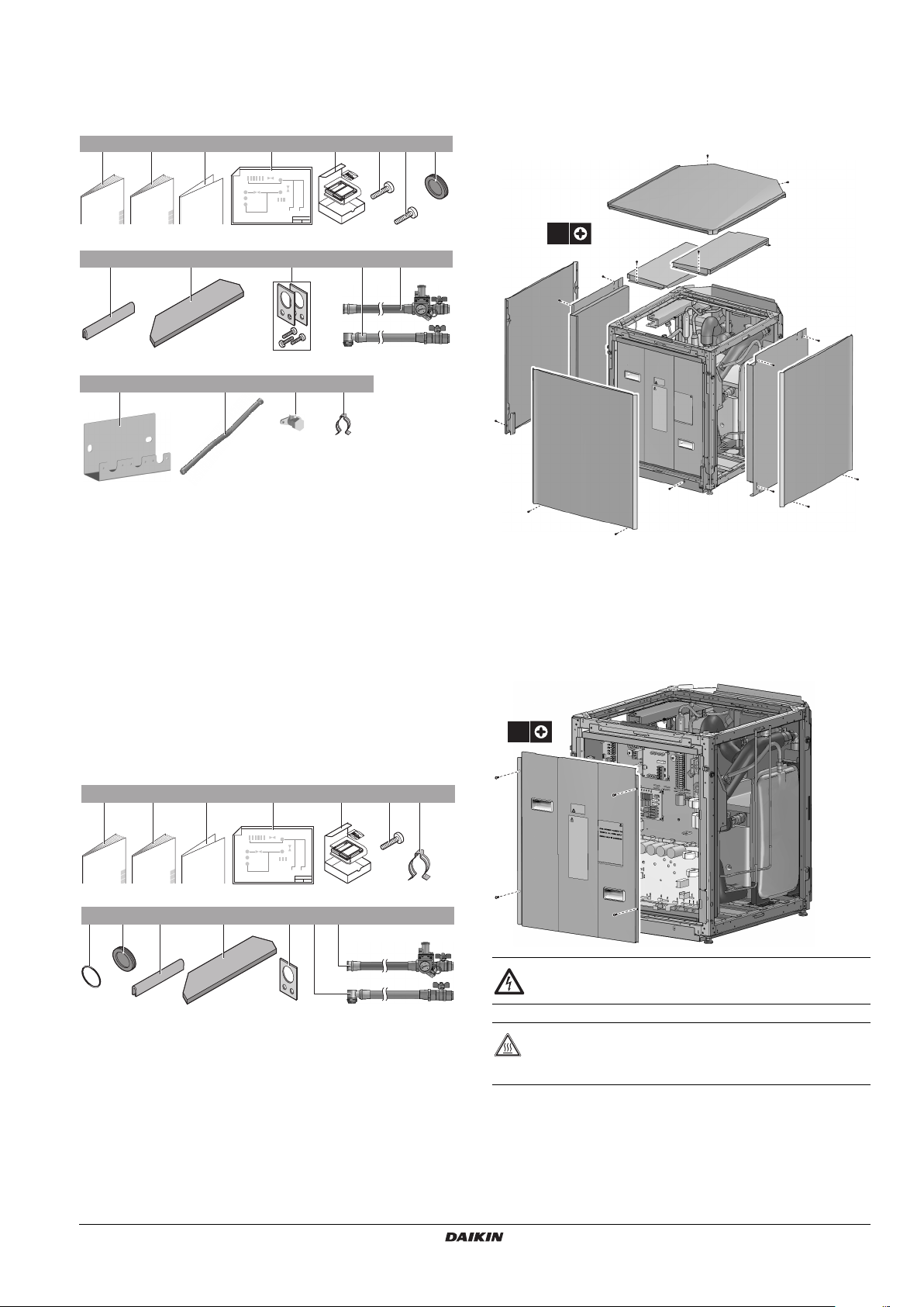
4.1. Accessories supplied with this unit
For the HXHD125, following accessories can be found in the unit:
12 31x46
1x 6x1x 1x 1x1x
9101x11
1x2x
8x74x
13
1x121x
+
14 15 16 17
1x 6x 3x 2x
1 Installation manual
2 Operation manual
3 Addendum installation manual
4 Wiring diagram
5 User interface kit (remote controller, 4 fixing screws, 2
plugs)
6 Stop valve fixing screws (6 screws)
7 Top plate fixing screws + sound bottom plate fixing screws
+ lifting fixing screws (8 screws)
8 Grommet (small)
9 Grommet (large)
10 Top plate insulation
11 Kit for lifting the unit
12 Flexible water outlet piping
13 Flexible water inlet piping (with manometer)
14 Support plate
15 Piping
16 Stop valves
17 Piping fixation clamps
For the HXHD200, following accessories can be found in the unit:
5.1. Opening the unit
To gain access to the unit, top plate, the drip plates and the front
85
plate need to be opened.
1
1
20x
2
2
2
2
5
5
4
4
4
3
3
1 Top plate
2 Drip plate
3 Front plate
4 Sound plate
5 Side plate
4
5
5
Once the unit is opened, access is possible to the main components.
To gain access to the electrical components, switch box needs to be
opened:
4x
12 31x46
1x 6x1x 1x 1x
10 11
1x2x82x91x
14
2x121x131x
75
2x
1 Installation manual
2 Operation manual
3 Unpacking instruction sheet
4 Wiring diagram
5 User interface kit (remote controller, 4 fixing screws, 2
plugs)
6 Screws (2x top fixing plate screws + 4x lifting plate screws)
7 Clamp
8 O-ring (spare part)
9 Grommet (small)
10 Grommet (large)
11 Top plate insulation
12 Lifting plate (for lifting the unit)
13 Flexible water outlet piping
14 Flexible water inlet piping (with manometer)
HXHD125AV1B + HXHD200AY1B
VRV IV system indoor unit
4P513552-1 – 2017.11
DANGER: ELECTRICAL SHOCK
See "2. General Safety precautions" on page 2.
DANGER: DO NOT TOUCH PIPING AND INTERNAL
PA RT S
See "2. General Safety precautions" on page 2.
Installation manual
4
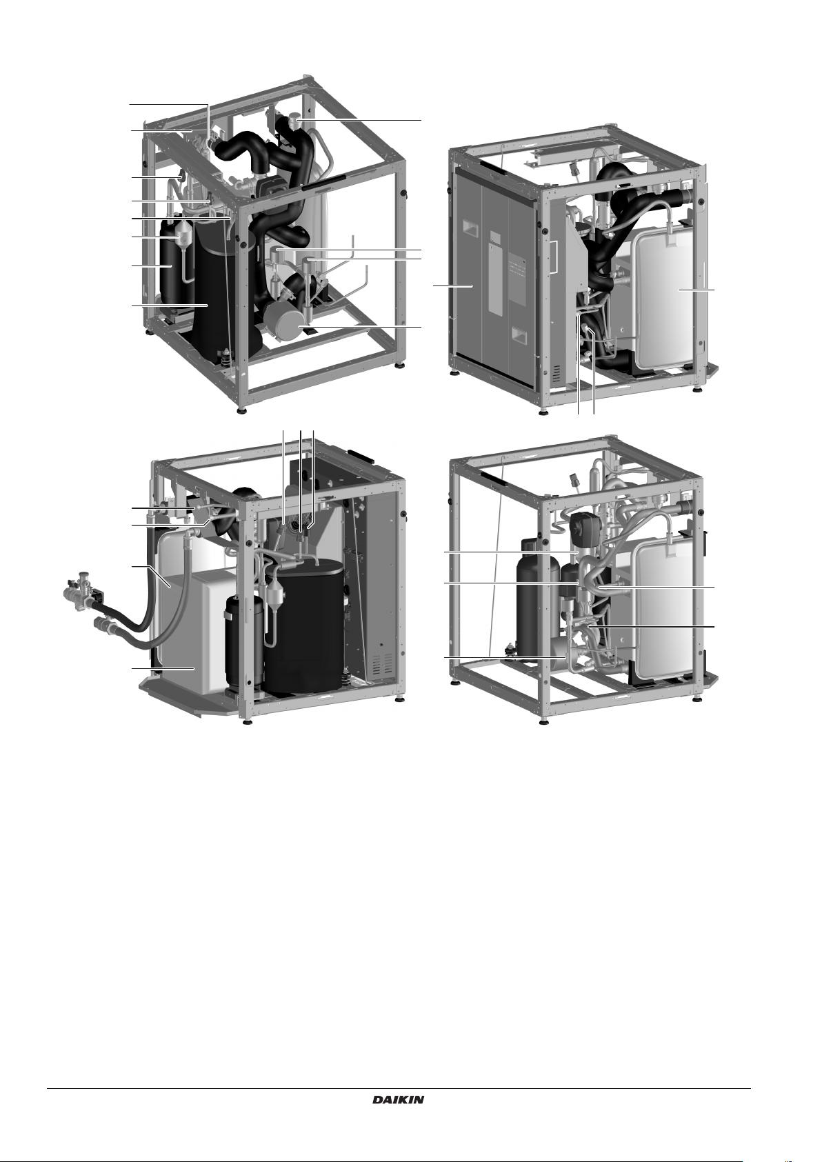
5.2. Main components in the HXHD125 unit
16
15
4
6
5
3
1
2
4
65
10
16
8
7
11
9
1718
15
14
12
13
1. R134a accumulator
2. R134a compressor
3. R134a discharge muffler
4. R134a low pressure sensor
5. R134a high pressure switch
6. R134a high pressure sensor
7. R134a expansion valve
8. R410A heating expansion valve
9. Heating pump
10. Air purge
11. Expansion vessel
12. Heating plate heat exchanger
13. Cascade plate heat exchanger
14. R410A HP/LP gas connection
15. R410A liquid connection
16. Switchbox
17. Service port R134a high
18. Service port R134a low
R6T
R4T
R7T
Sensor information:
R3T R410A liquid temperature
R4T Water return temperature
R5T Heating leaving water temperature
R6T R134a discharge temperature
R7T R134a liquid temperature
R5T
R3T
Installation manual
5
HXHD125AV1B + HXHD200AY1B
VRV IV system indoor unit
4P513552-1 – 2017.11
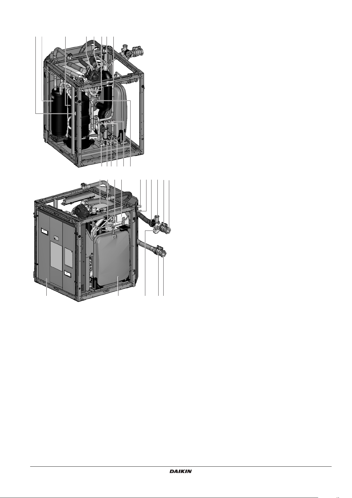
5.3. Main components in the HXHD200 unit
18
17
120192
1623
2
22 22
2
10
2421 56
4
123
14
11
13 15 7 8
7
9
1. Air purge valve
Remaining air in the water circuit will be automatically removed
via the air purge valve.
2. Temperature sensors (thermistors)
Temperature sensors determine the water and refrigerant
temperature at various points in the circuit.
3. Switch box
The switch box contains the main electronic and electrical parts
of the indoor unit.
4. Heat exchangers
5. R410A HP/LP gas connection
6. R410A liquid connection
7. Shut-off valves
The shut-off valves on the water inlet connection and water
outlet connection allow isolation of the indoor unit water circuit
side from the residential water circuit side. This facilitates
draining and filter cleaning of the indoor unit.
8. Water inlet connection
9. Water outlet connection
10. Drain valve
11. Water filter
The water filter removes dirt from the water to prevent damage
to the pump or blockage of the heat exchanger. The water filter
must be cleaned on a regular base. See "11.1. Maintenance
activities" on page 44.
12. Expansion vessel (12 l)
13. Manometer
The manometer allows readout of the water pressure in the
water circuit.
14. Pump
The pump circulates the water in the water circuit.
15. Pressure relief valve
The pressure relief valve prevents excessive water pressure in
the water circuit by opening at 3 bar and discharging some
water.
16. Service ports R134a
17. Compressor
18. Accumulator
19. 3-way valve (option) (delivered with the EKHTS* domestic hot
water tank)
The motorized 3-way valve controls whether the water outlet is
used for space heating or the domestic hot water tank.
20. 4-way valve
21. Thermal cut-out
22. Electronic expansion valve
HXHD125AV1B + HXHD200AY1B
VRV IV system indoor unit
4P513552-1 – 2017.11
Installation manual
6
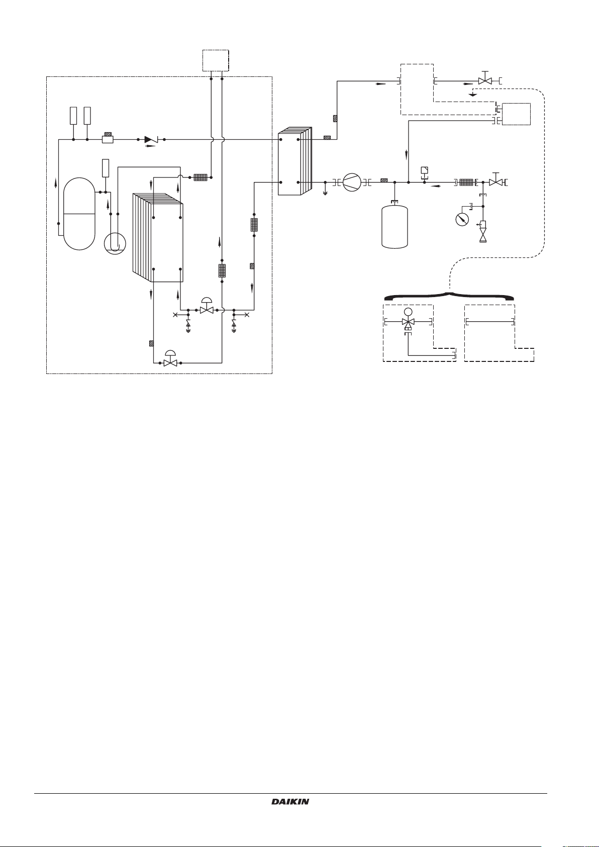
5.4. Functional diagram for the HXHD125 unit
1
2
17
18
A/B
7
8
S1PH
B1PH
R6T
R5T
5
Q2L
3
4
13
M1P
R4T
B1PL
6
9
16
17
6
19
14
11
6
15
22
20
21
10
R3T
12 12
K1E
K2E
R7T
6
K1S
M
1 Refrigerant side
2 Outdoor unit
3 Option domestic hot water tank
4 Muffler
5 Check valve
6 Filter
7 Field piping Ø12.7
8 Field piping Ø9.52
9 Compressor
10 Accumulator
11 Cascade heat exchanger
12 Service port
13 Heating heat exchanger
14 Drain port
15 Expansion vessel
16 Air purge
17 Shut-off valve
18 Water outlet
19 Water inlet
20 Blow off
21 Safety valve
22 Pressure gauge
A Install the 3-way valve in case of domestic hot water tank
B Standard
B1PH High pressure sensor
B1PL Low pressure sensor
K1E Electronic expansion valve (R410A)
K1S 3-way valve
K2E Electronic expansion valve (R134a)
M1P Pump
Q2L Thermistor protector water piping
S1PH High pressure switch
AB
Installation manual
7
HXHD125AV1B + HXHD200AY1B
VRV IV system indoor unit
4P513552-1 – 2017.11
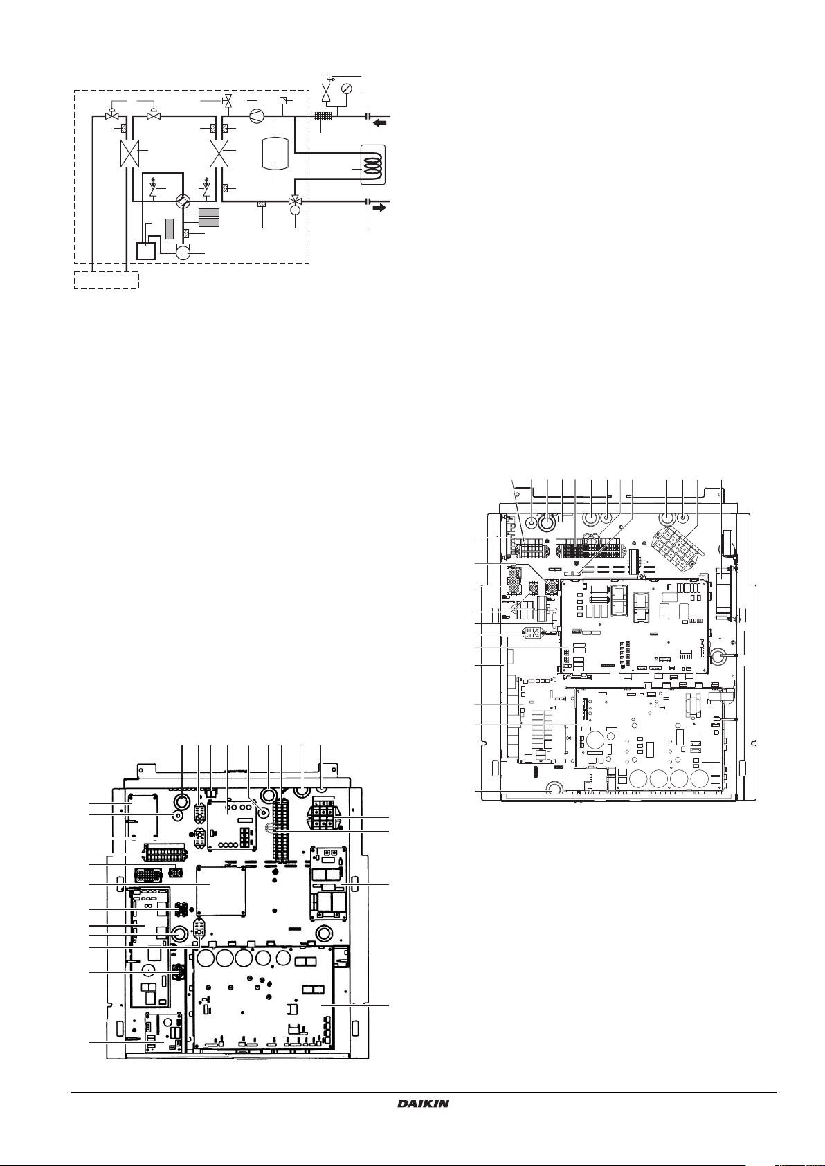
5.5. Functional diagram for the HXHD200 unit
10
2
1
1 Outdoor unit
2 Indoor unit
3 Refrigerant-refrigerant heat exchanger
4 Accumulator
5 Compressor
6 Service port
7 Refrigerant-water heat exchanger
8 Drain valve
9 Electronic expansion valve
10 Pressure relief valve
11 Pump
12 Air purge valve
13 Manometer
14 Expansion vessel
15 Water filter
16 Fill valve (field supply)
17 Shut-off valve water inlet
18 Shut-off valve water outlet
19 Domestic hot water tank (optional)
20 Motorized 3-way valve (optional)
21 Thermal cut-out (Q2L)
22 High pressure switch (S1PH)
23 High pressure sensor (B1PH)
24 Low pressure sensor (B1PL)
25 Discharge thermistor (R6T)
26 Leaving water thermistor (R5T)
27 Returning water thermistor (R4T)
28 Liquid thermistor R134a (R7T)
29 Liquid thermistor R410A (R3T)
89
2829
3
6
6
4
24
11
27
7
21
22
23
25
5
12
15 17
14
M
26 20 18
13
16
19
5.6. Switch box main components for the HXHD125 unit
62 161718 21 15 10
15
1 Main PCB
2 Control PCB
3 Inverter PCB
4 QA PCB
5 Filter PCB
6 Multi tenant PCB
7 Digital I/O PCB (optional)
8 Demand PCB (optional)
9 Terminal block X1M
Main terminal block which allows easy connection of field
wiring for power supply
10 Terminal block X2M
Field wiring terminal block for high voltage connections.
11 Terminal block X3M
Field wiring terminal block for low voltage connections.
12 DC connector X1Y/X4Y
13 AC connector X3Y
14 Pump connector X2Y
15 Cable tie mountings
The cable tie mountings allow to fix the field wiring with
cable ties to the switch box to ensure strain relief.
16 Power wiring entry
17 High voltage field wiring entry
18 Low voltage field wiring entry
19 Compressor cable entry
20 Interface relay K1A
21 Interface relay K2A
22 Interface relay K3A
23 Wiring bridges
5.7. Switch box main components for the HXHD200 unit
14
12
13
20
21
16171810 9112315 1515
227
8
4
1
2
3
6
8
15
22
11
12
7
13
1
19
20
14
4
HXHD125AV1B + HXHD200AY1B
VRV IV system indoor unit
4P513552-1 – 2017.11
9
23
5
3
19
1 Main PCB
2 Control PCB
3 Inverter PCB
4 Inverter control PCB
5 Filter PCB
6 Digital I/O PCB (optional)
7 Demand PCB (optional)
8 Terminal block X1M
Main terminal block which allows easy connection of field
wiring for power supply
9 Terminal block X3M
Field wiring terminal block for low voltage connections.
10 Terminal block X2M
Field wiring terminal block for high voltage connections.
11 Low voltage connector X1Y
12 Pump connector X2Y
13 High voltage connector X3Y
14 Cable tie mountings
The cable tie mountings allow to fix the field wiring with
cable ties to the switch box to ensure strain relief.
15 Power wiring entry
16 High voltage field wiring entry
Installation manual
8
17 Low voltage field wiring entry
18 Compressor cable entry
19 Interface relay K1A
20 Wiring bridges
21 Fuse F1
22 Fuse F2
6. DESIGN OF THE WATER CIRCUIT
The purpose of this chapter is to give guidelines for the design of the
water circuit.
Precautions and guidelines that have impact to the unit prescribed in
this manual are included into this chapter.
Actions needed during the installation of the unit prescribed in this
manual are described in the chapter "7.6. Water piping" on page 19.
NOTICE
It is strongly recommended to install an additional filter on
the heating water circuit. Especially to remove metallic
particles from the field heating piping, it is advised to use a
magnetic or cyclone filter which can remove small
particles. Small particles can damage the unit and will not
be removed by the standard filter of the heat pump unit.
6.1. Selection of the type of heat emitters
The selection of the heat emitter is the choice of the end customer.
The choice of the heat emitter will define the needed water
temperature from the unit.
Based on the needed water temperature for the heat emitters,
following range can be defined:
1. Low temperature (Leaving water temperature range from 25°C
to 40°C).
Typical example: floor heating.
2. Medium temperature (Leaving water temperature range from
40°C to 55°C).
Typical example: low temperature radiators or convectors.
3. High temperature (Leaving water temperature range from 55°C
to 75°C).
Typical example: radiators.
Once the heat emitters are chosen, the capacity of these heat
emitters should be defined and from this the dimensioning and
position of the heat emitters in the different rooms should be decided.
An important parameter of the heat emitters is the temperature
difference between entering water and leaving water.
This will define the water flow in the system.
Finally, the piping layout from the heat source to the different heat
emitters needs to be drawn.
This will finally define following important parameters:
■ Minimal water volume in the system.
■ Maximal water volume in the system.
■ Minimal and maximal water flow in system.
■ Maximal pressure drop in the system.
NOTICE
In refurbishment applications, the water system will
already be fixed. It is utmost important for these kind of
installations to know the parameters mentioned above.
6.2. General precautions concerning water circuit
Before continuing the installation of the unit, check the following
points:
■ The maximum water pressure is 3 bar.
■ The maximum water temperature is 80°C.
■ Provide adequate safeguards in the water circuit to be sure that
the water pressure will never exceed the maximum allowable
working pressure (3 bar).
■ Shut-off valves from flexible hoses delivered with the unit should
be installed so that normal servicing can be accomplished
without draining the system.
■ Drain taps must be provided at all low points of the system to
permit complete drainage of the circuit during maintenance or
service to the unit. A drain valve is provided in the unit to drain
the water from the unit water system.
■ Be sure to provide a proper drain for the pressure relief valve to
avoid any water coming into contact with electrical parts.
■ Air vents must be provided at all high points of the system. The
vents shall be located at points which are easily accessible for
servicing. An automatic air purge is provided inside the indoor
unit. Check that this air purge valve is not tightened too much so
that automatic release of air in the water circuit remains
possible.
■ Take care that the components installed in the field piping can
withstand the water pressure and temperature.
■ Always use materials which are compatible with the water used
in the system and with the materials used on the unit.
■ Select piping diameter in relation to required water flow and
available ESP of the pump.
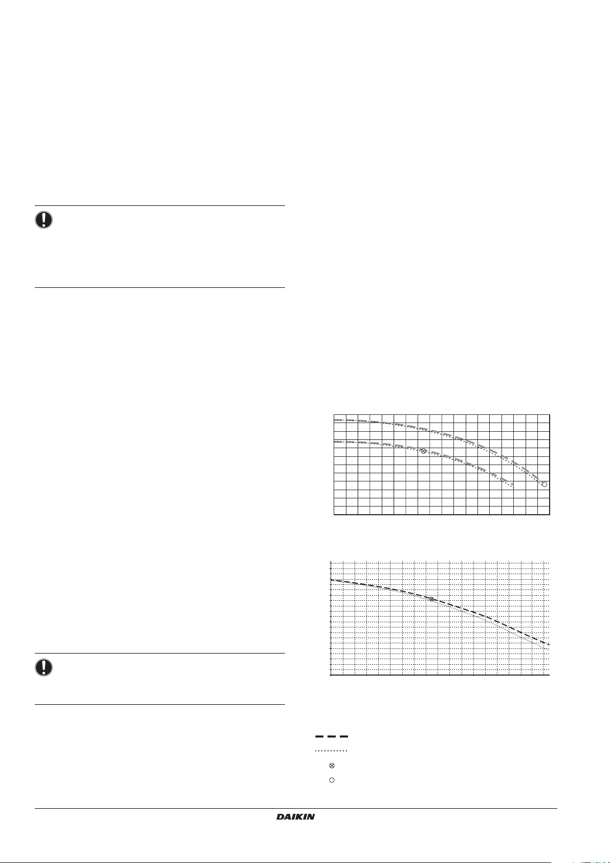
When designing the hydraulic system always consider the available
static pressure of the indoor unit.
HXHD125
120
110
100
90
80
70
60
50
ESP [kPa]
40
30
20
10
0
5 7 9 11131517192123 27 3133 3725 29 35 39 41
flow [l/min]
HXHD200
100
90
80
70
]
60
kPa
[
50
40
ESP
30
20
10
0
19171521 23 25 27 29 31 33 35 37 39 41 43 45 47 49 51
flow[l/min
ESP (kPa) External static pressure (kPa)
flow (l/min) Flow (l/min)
Without 3-way valve
Including 3-way valve
Maximum external static pressure if
Maximum external static pressure if
]
∆T=10°C (heating)
∆T=5°C (heating)
Installation manual
9
HXHD125AV1B + HXHD200AY1B
VRV IV system indoor unit
4P513552-1 – 2017.11
INFORMATION
■ The ESP curve is the maximum ESP curve. The pump
of the indoor module is inverter controlled and
controls to have a fixed ∆T between return and
leaving water temperature.
■ In case of installing a domestic hot water tank there is
an additional pressure drop over the 3-way valve
(delivered as accessory with the tank).
Check that the total water volume in the installation, excluding the
internal water volume of the unit, is 20 l minimum.
NOTICE
In most applications this miminum water volume will have a
satisfying result.
In critical processes or in rooms with a high heat load
though, extra water volume might be required.
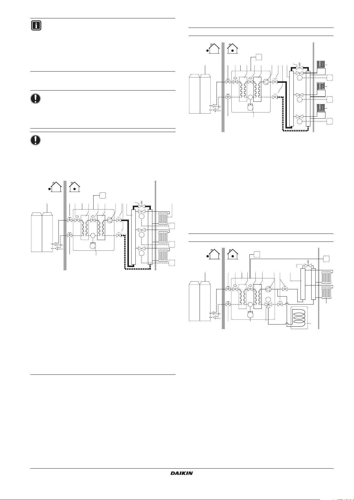
6.3. Application examples
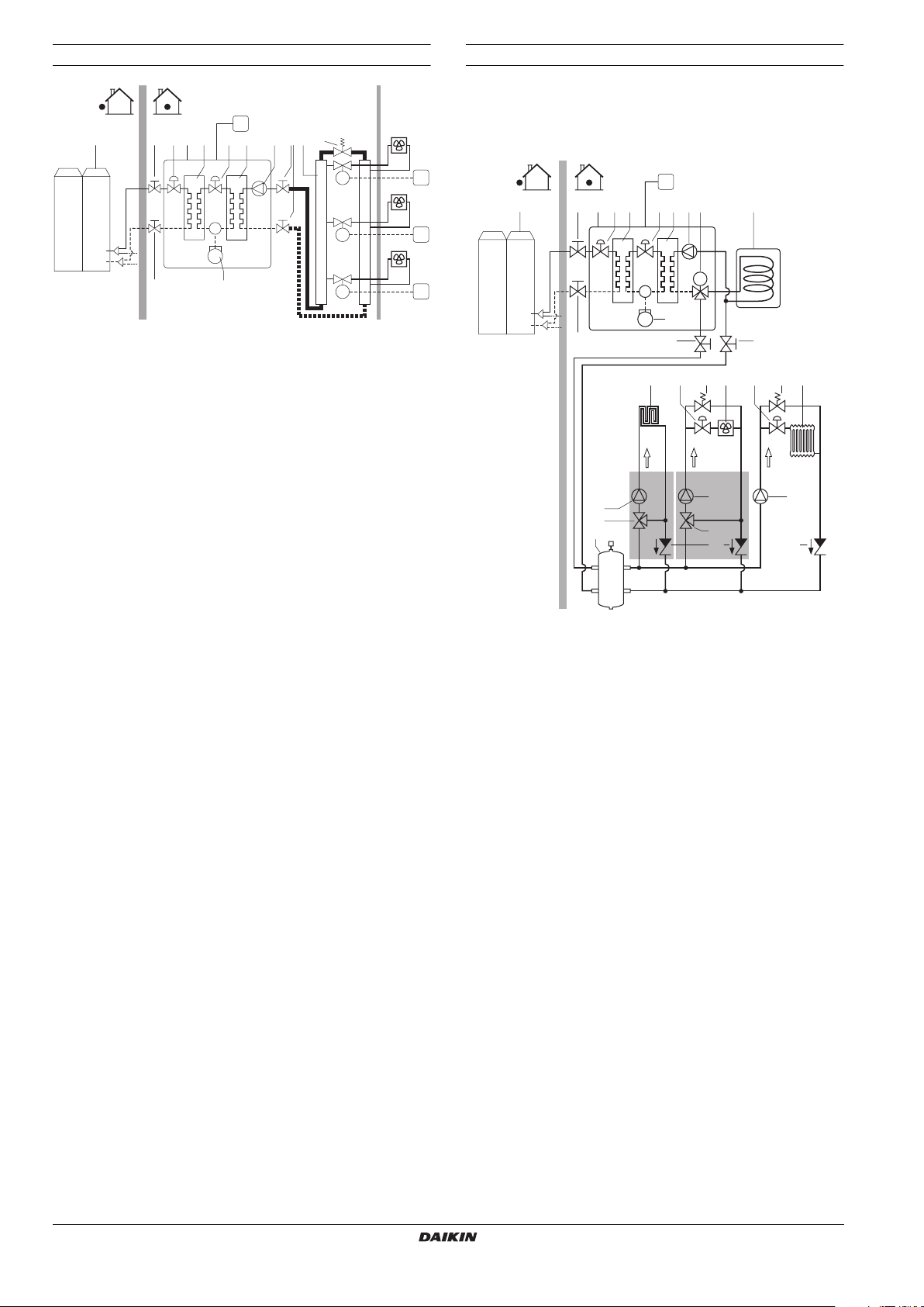
Floor heating without domestic hot water tank
1112
C1
11
512
778432 916
M3
M2
M1
A B
10
FHL3
T3
10
FHL2
T2
10
FHL1
T1
NOTICE
When circulation in each space heating/radiator loop is
controlled by remotely controlled valves, it is important that
this minimum water volume is kept even if all the valves are
closed.
Example (See "6.3. Application examples" on page 10.)
A B
1112
1 Outdoor unit
2 Indoor unit
3 Refrigerant heat exchanger
4 Water heat exchanger
5 Compressor
6 Pump
7 Shut-off valve
8 Collector (field supply)
9 By-pass valve (field supply)
10 Radiator (field supply)
11 Electronic expansion valve
12 Indoor unit refrigerant stop valve
C1 Remote controller
M1...M3 Individual motorized valve to control loop radiators (field
supply)
T1...T3 Individual room thermostat (field supply)
A Installation space
B Living room
C1
11
512
7 8432 91610
M3
M2
M1
T3
T2
T1
1 Outdoor unit
2 Indoor unit
3 Refrigerant heat exchanger
4 Water heat exchanger
5 Compressor
6 Pump
7 Shut-off valve
8 Collector (field supply)
9 By-pass valve (field supply))
10 FHL: Floor heating loop (field supply)
11 Electronic expansion valve
12 Indoor unit refrigerant stop valve
C1 Remote controller
M1...M3 Individual motorized valve to control loop radiators (field
supply)
T1...T3 Individual room thermostat (field supply)
A Installation place
B Living room
Radiator with domestic hot water tank
C2
6
M
514
8
1 Outdoor unit
2 Indoor unit
3 Refrigerant heat exchanger
4 Water heat exchanger
5 Compressor
6 Pump
7 Shut-off valve
8 Motorized 3-way valve (optional)
9 Domestic hot water tank (optional)
10 Collector
11 Radiator (field supply)
12 Electronic expansion valve
13 By-pass valve (field supply)
14 Indoor unit refrigerant stop valve
C1 Remote controller (master)
C2 Remote controller (slave)
A Installation place
B Living room
A B
C1
10 13
743 121214 21
11
9
HXHD125AV1B + HXHD200AY1B
VRV IV system indoor unit
4P513552-1 – 2017.11
Installation manual
10
Fan coils without domestic hot water tank
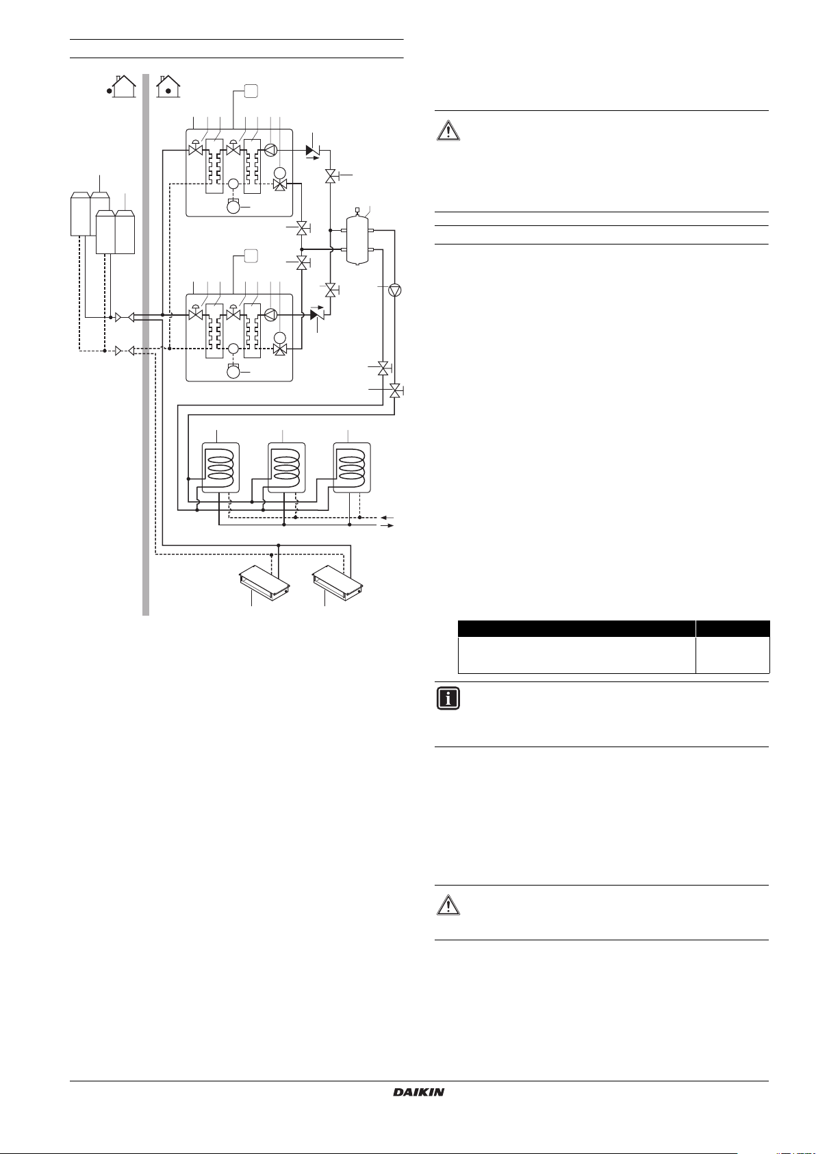
Application example with several heat emitters
A B
1112
1 Outdoor unit
2 Indoor unit
3 Refrigerant heat exchanger
4 Water heat exchanger
5 Compressor
6 Pump
7 Shut-off valve
8 Collector (field supply)
9 By-pass valve (field supply)
10 FCU: Fan coil unit (field supply)
11 Electronic expansion valve
12 Indoor unit refrigerant stop valve
C1 Remote controller
M1...M3 Individual motorized valve to control loop radiators (field
supply)
T1...T3 Individual room thermostat (field supply)
A Installation place
B Living room
C1
11
512
7 8432 916
M3
M2
M1
10
FCU3
10
FCU2
10
FCU1
T3
T2
T1
Using different heat emitters means using different water set points
for the system.
Such installations must be done using a balancing bottle and each
kind of heat emitter should have a specific pump.
C1
1
3 34 5 6 8221
7
M
9
21
19
18
11
10 10
1512 14 141613
FHL
35°C
TRD1 TRD2
45°C
FCU
18
20 20
17
65°C
1919
1 Outdoor unit
2 Indoor unit
3 Electronic expansion valve
4 Refrigerant heat exchanger
5 Water heat exchanger
6 Pump
7 Motorized 3-way valve (optional)
8 Domestic hot water tank (optional)
9 Compressor
10 Shut-off valve
11 Balancing bottle (field supply)
12 FHL: Floor heating loop (field supply)
13 Shut-off valve (field supply)
14 By-pass valve (field supply)
15 FCU: Fan coil unit (field supply)
16 Shut-off valve (field supply)
17 Radiator (field supply)
18 Mixing valve (field supply)
19 Pump (field supply)
20 Non-return valve (field supply)
C1 Remote controller
TRD1 Temperature reducing device 1 (field supply)
TRD2 Temperature reducing device 2 (field supply)
Refer to chapter "9.7. Multiple set point control" on page 39 for more
information about the configuration of your system.
Installation manual
11
HXHD125AV1B + HXHD200AY1B
VRV IV system indoor unit
4P513552-1 – 2017.11
Multiple hydrobox connection with domestic hot water tank
7. INSTALLATION OF THE UNIT
1
1
1 Outdoor unit
2 Indoor unit
3 Electronic expansion valve
4 Refrigerant heat exchanger
5 Water heat exchanger
6 Pump
7 Motorized 3-way valve (optional)
8 Domestic hot water tank (field supply)
9 Compressor
10 Shut-off valve (field supply)
11 Balancing bottle (field supply)
12 VRV DX indoor unit
13 Non-return valve (field supply)
14 Domestic hot water outlet
15 Domestic hot water inlet
16 Pump (field supply)
C1 Remote controller
C1
3 34 5 62
3 34 5 62
8 8 8
C1
7
13
M
9
10
10
7
10
M
13
9
1212
10
10
10
16
11
15
14
7.1. Selecting an installation location
WARNING
Be sure to provide for adequate measures in order to
prevent that the unit is used as a shelter by small animals.
Small animals making contact with electrical parts can
cause malfunctions, smoke or fire. Please instruct the
customer to keep the area around the unit clean and clear.
General precautions on installation location
Select an installation site that meets the following requirements:
■ The foundation must be strong enough to support the weight of
the unit. The floor is flat to prevent vibrations and noise
generation and to have sufficient stability.
This is especially of importance when the optional domestic hot
water tank is installed on top of the unit.
■ The space around the unit is adequate for maintenance and
servicing (refer to "Service space of the unit" on page 15).
■ The space around the unit allows for sufficient air circulation.
■ There is no danger of fire due to leakage of inflammable gas.
■ The equipment is not intended for use in a potentially explosive
atmosphere.
■ Select the location of the unit in such a way that the sound
generated by the unit does not disturb anyone, and the location
is selected according the applicable legislation.
If the sound is measured under actual installation conditions, the
measured value will be higher than the sound pressure level
mentioned in "13. Unit specifications" on page 50 due to
environmental noise and sound reflections.
Choose the installation location carefully and do not install in a
sound sensitive environment (e.g. living room, bedroom, …)
■ All piping lengths and distances have been taken into
consideration (For requirements of piping length for the
refrigerant piping, refer to the outdoor unit installation manual).
Requirement Value
Maximum allowable distance between the domestic
hot water tank and the indoor unit (only for
installations with domestic hot water tank).
INFORMATION
If the installation is equipped with a domestic hot water
tank (optional), please refer to the domestic hot water tank
installation manual.
■ Take care that in the event of a water leak, water cannot cause
any damage to the installation space and surroundings.
■ The installation location is frost-free.
■ Be sure that sufficient precautions are taken, in accordance with
the applicable legislation, in case of refrigerant leakage.
■ When installing the unit in a small room, take measures in order
to keep the refrigerant concentration from exceeding allowable
safety limits in the event of a refrigerant leak.
10 m
HXHD125AV1B + HXHD200AY1B
VRV IV system indoor unit
4P513552-1 – 2017.11
WARNING
Excessive refrigerant concentrations in a closed room can
lead to oxygen deficiency.
■ Do not climb, sit or stand on top of the unit.
■ Do not place any objects or equipment on top of the unit (top
plate).
■ Do not install the unit in places often used as workplace. In case
of construction works, where a lot of dust is created, the unit
must be covered.
■ Do not install the unit in places with high humidity (e.g.
bathroom) (max humidity (RH)=85%).
Installation manual
12
7.2. Dimensions and service space
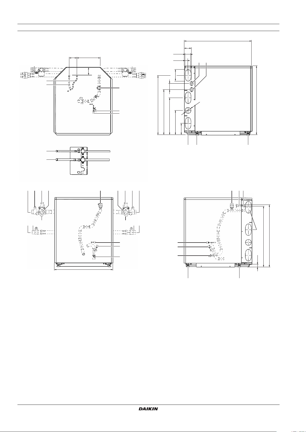
Dimensions of unit
HXHD125
17
18
694
74
79 242
2x 60
38
13
14
81
2
1
8
120
62
708
3
4
611
465
∅60
381
251
120
15 16 16
6 68 8 2 15
9 9
11 11
9 9
12 12
10
5
10
3
4
7
600
1 HP/LP gas pipe connection Ø12.7 solder (R410A)
2 Liquid pipe connection Ø9.52 solder (R410A)
3 R134a service ports 5/16" flare (low)
4 R134a service ports 5/16" flare (high)
5 Pressure gauge
6 Blow off valve
7 Drain valve water circuit
8 Air purge
9 Shut-off valves
10 Water filter
11 Water in connection G1" (female)
12 Water out connection G1" (female)
13 Control wiring intake (knock-out hole Ø37)
14 Power supply wiring intake (knock-out hole Ø37)
15 Knock-out hole for refrigerant piping and water piping
16 Levelling feet
17 Liquid stop valve Ø9.52 solder (R410A)
18 HP/LP stop valve Ø12.7 solder (R410A)
15
637
622
3
4
7
16
16
26.5
Installation manual
13
HXHD125AV1B + HXHD200AY1B
VRV IV system indoor unit
4P513552-1 – 2017.11
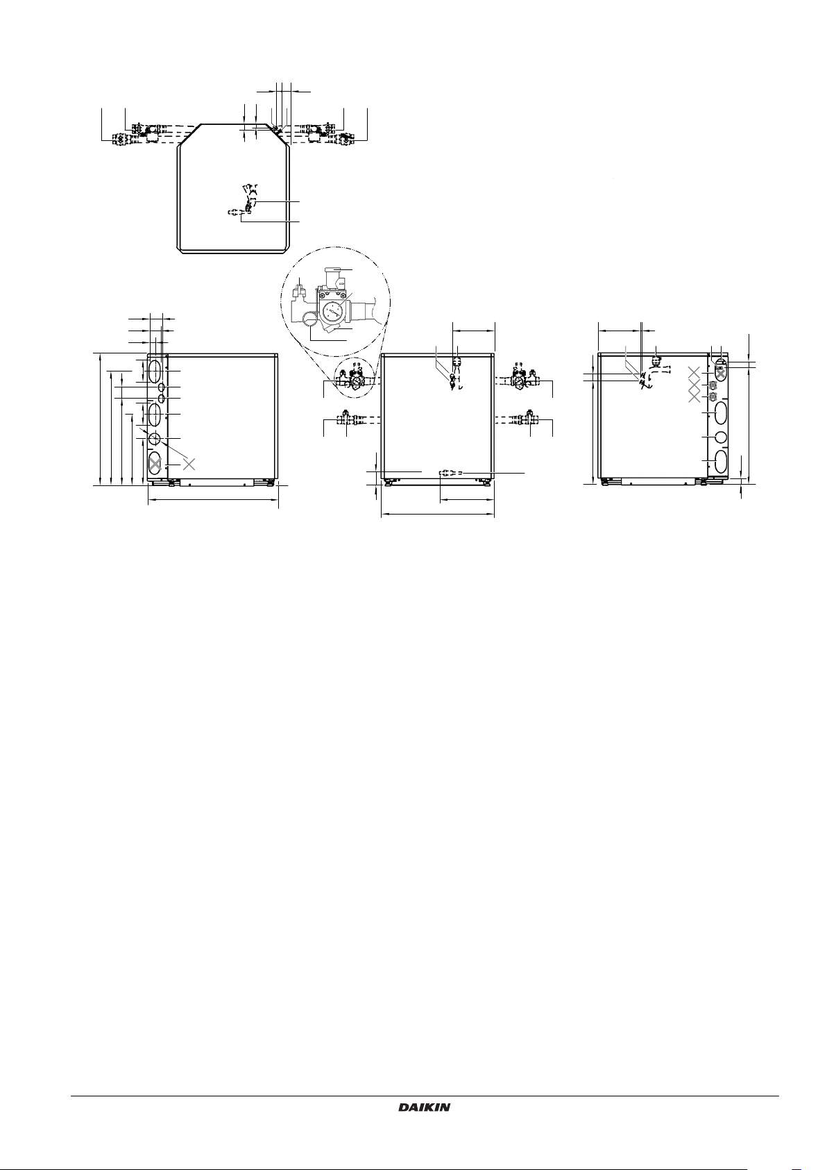
HXHD200
24 45
16
31
21
1010 1111
7
6
74
60
38
14
62
708
611
465
381
10 Drain valve
11 Water filter
12 Expansion vessel (12 l)
13 Manometer
14 Pump
15 Pressure relief valve
16 Service ports R134a
17 Compressor
18 Accumulator
19 3-way valve (option) (delivered with the EKHTS* domestic
20 4-way valve
21 Thermal cut-out
22 Electronic expansion valve
23 T-piece (option) (delivered with the EKHTS* domestic hot
HXHD125AV1B + HXHD200AY1B
VRV IV system indoor unit
4P513552-1 – 2017.11
12
13
14
120
14
Ø60
251 120
14
1 Air purge valve
Remaining air in the water circuit will be automatically
removed via the air purge valve.
2 Temperature sensors (thermistors)
Temperature sensors determine the water and refrigerant
temperature at various points in the circuit.
3 Switch box
The switch box contains the main electronic and electrical
parts of the indoor unit.
4 Heat exchangers
5 Refrigerant liquid connection R410A
6 Refrigerant gas connection R410A
7 Shut-off valves
The shut-off valves on the water inlet connection and water
outlet connection allow isolation of the indoor unit water
circuit side from the residential water circuit side. This
facilitates draining and filter cleaning of the indoor unit.
8 Water inlet connection
9 Water outlet connection
The water filter removes dirt from the water to prevent
damage to the pump or blockage of the heat exchanger.
The water filter must be cleaned on a regular base. See
"11.1. Maintenance activities" on page 44.
The manometer allows readout of the water pressure in the
water circuit.
The pump circulates the water in the water circuit.
The pressure relief valve prevents excessive water
pressure in the water circuit by opening at 3 bar and
discharging some water.
hot water tank)
The motorized 3-way valve controls whether the water
outlet is used for space heating or the domestic hot water
tank.
water tank)
694
8
5
4
9
143
16
10
8
11 8 11
69
15
292
600
227 7
14
21
28
77
33
37
12
10
552
6
13
14
14
14
Installation manual
622
26.5
14
 Loading...