


Daikin HPSU compact 304, HPSU compact 308, HPSU compact 508, HPSU compact 516 Installation manuals
For the qualified installer
ROTEX HPSU compact (V5.2)
Installation and maintenance
manual
Solar tank with integrated interior heat pump unit
For the types
HPSU compact 304
HPSU compact 308
HPSU compact 508
HPSU compact 516
GB
Edition 07/2017
CE - DECLARATION-OF-CONFORMITY
CE - KONFORMITÄTSERKLÄRUNG
CE - DECLARATION-DE-CONFORMITE
CE - CONFORMITEITSVERKLARING
CE - DECLARACION-DE-CONFORMIDAD
CE - DICHIARAZIONE-DI-CONFORMITA
CE - ǻHȁȍȈǾ ȈȊȂȂȅȇĭȍȈǾȈ
CE - DECLARAÇÃO-DE-CONFORMIDADE
CE - ɁȺəȼɅȿɇɂȿ-Ɉ-ɋɈɈɌȼȿɌɋɌȼɂɂ
CE - OVERENSSTEMMELSESERKLÆRING
CE - FÖRSÄKRAN-OM-ÖVERENSTÄMMELSE
CE - ERKLÆRING OM-SAMSVAR
CE - ILMOITUS-YHDENMUKAISUUDESTA
CE - PROHLÁENÍ-O-SHODċ
CE - IZJAVA-O-USKLAĈENOSTI
CE - MEGFELELėSÉGI-NYILATKOZAT
CE - DEKLARACJA-ZGODNOĝCI
CE - DECLARAğIE-DE-CONFORMITATE
CE - IZJAVA O SKLADNOSTI
CE - VASTAVUSDEKLARATSIOON
CE - ȾȿɄɅȺɊȺɐɂə-ɁȺ-ɔɈɌȼȿɌɋɌȼɂȿ
CE - ATITIKTIES-DEKLARACIJA
CE - ATBILSTƮBAS-DEKLARƖCIJA
CE - VYHLÁSENIE-ZHODY
CE - UYUMLULUK-BEYANI
01
are in conformity with the following standard(s) or other normative document(s), provided that these are used in accordance with our
instructions:02der/den folgenden Norm(en) oder einem anderen Normdokument oder -dokumenten entspricht/entsprechen, unter der Voraussetzung,
daß sie gemäß unseren Anweisungen eingesetzt werden:03sont conformes à la/aux norme(s) ou autre(s) document(s) normatif(s), pour autant qu'ils soient utilisés conformément à nos instructions:04conform de volgende norm(en) of één of meer andere bindende documenten zijn, op voorwaarde dat ze worden gebruikt overeenkomstig
onze instructies:05están en conformidad con la(s) siguiente(s) norma(s) u otro(s) documento(s) normativo(s), siempre que sean utilizados de acuerdo con
nuestras instrucciones:
06
sono conformi al(i) seguente(i) standard(s) o altro(i) documento(i) a carattere normativo, a patto che vengano usati in conformità alle
nostre istruzioni:
07
İȓȞĮȚ ıȪȝijȦȞĮ ȝİ IJȠ(Į) ĮțȩȜȠȣșȠ(Į) ʌȡȩIJȣʌȠ(Į) Ȓ ȐȜȜȠ ȑȖȖȡĮijȠ(Į) țĮȞȠȞȚıȝȫȞ, ȣʌȩ IJȘȞ ʌȡȠȨʌȩșİıȘ ȩIJȚ ȤȡȘıȚȝȠʌȠȚȠȪȞIJĮȚ ıȪȝijȦȞĮ
ȝİ IJȚȢ ȠįȘȖȓİȢ ȝĮȢ:
08
estão em conformidade com a(s) seguinte(s) norma(s) ou outro(s) documento(s) normativo(s), desde que estes sejam utilizados de
acordo com as nossas instruções:09ɫɨɨɬɜɟɬɫɬɜɭɸɬ ɫɥɟɞɭɸɳɢɦ ɫɬɚɧɞɚɪɬɚɦ ɢɥɢ ɞɪɭɝɢɦ ɧɨɪɦɚɬɢɜɧɵɦ ɞɨɤɭɦɟɧɬɚɦ, ɩɪɢ ɭɫɥɨɜɢɢ ɢɯ ɢɫɩɨɥɶɡɨɜɚɧɢɹ ɫɨɝɥɚɫɧɨ ɧɚɲɢɦ
ɢɧɫɬɪɭɤɰɢɹɦ:
10
overholder følgende standard(er) eller andet/andre retningsgivende dokument(er), forudsat at disse anvendes i henhold til vore
instrukser:11respektive utrustning är utförd i överensstämmelse med och följer följande standard(er) eller andra normgivande dokument, under
förutsättning att användning sker i överensstämmelse med våra instruktioner:12respektive utstyr er i overensstemmelse med følgende standard(er) eller andre normgivende dokument(er), under forutssetning av at
disse brukes i henhold til våre instrukser:13vastaavat seuraavien standardien ja muiden ohjeellisten dokumenttien vaatimuksia edellyttäen, että niitä käytetään ohjeidemme
mukaisesti:14za pĜedpokladu, e jsou vyuívány v souladu s naimi pokyny, odpovídají následujícím normám nebo normativním dokumentĤm:15u skladu sa slijedeüim standardom(ima) ili drugim normativnim dokumentom(ima), uz uvjet da se oni koriste u skladu s naim uputama:
16
megfelelnek az alábbi szabvány(ok)nak vagy egyéb irányadó dokumentum(ok)nak, ha azokat elĘírás szerint használják:17speániają wymogi nastĊpujących norm i innych dokumentów normalizacyjnych, pod warunkiem Īe uĪywane są zgodnie z naszymi
instrukcjami:
18
sunt în conformitate cu următorul (următoarele) standard(e) sau alt(e) document(e) normativ(e), cu condiĠia ca acestea să fie utilizate în
conformitate cu instrucĠiunile noastre:19skladni z naslednjimi standardi in drugimi normativi, pod pogojem, da se uporabljajo v skladu z naimi navodili:20on vastavuses järgmis(t)e standardi(te)ga või teiste normatiivsete dokumentidega, kui neid kasutatakse vastavalt meie juhenditele:21ɫɴɨɬɜɟɬɫɬɜɚɬ ɧɚ ɫɥɟɞɧɢɬɟ ɫɬɚɧɞɚɪɬɢ ɢɥɢ ɞɪɭɝɢ ɧɨɪɦɚɬɢɜɧɢ ɞɨɤɭɦɟɧɬɢ, ɩɪɢ ɭɫɥɨɜɢɟ, ɱɟ ɫɟ ɢɡɩɨɥɡɜɚɬ ɫɴɝɥɚɫɧɨ ɧɚɲɢɬɟ
ɢɧɫɬɪɭɤɰɢɢ:
22
atitinka emiau nurodytus standartus ir (arba) kitus norminius dokumentus su sąlyga, kad yra naudojami pagal mnjsǐ nurodymus:23tad, ja lietoti atbilstoi raotƗja norƗdƯjumiem, atbilst sekojoiem standartiem un citiem normatƯviem dokumentiem:24sú v zhode s nasledovnou(ými) normou(ami) alebo iným(i) normatívnym(i) dokumentom(ami), za predpokladu, e sa pouívajú v súlade
s naim návodom:25ürünün, talimatlarmza göre kullanlmas koúuluyla aúa÷daki standartlar ve norm belirten belgelerle uyumludur:
01
Directives, as amended.02Direktiven, gemäß Änderung.03Directives, telles que modifiées.04Richtlijnen, zoals geamendeerd.05Directivas, según lo enmendado.06Direttive, come da modifica.07ȅįȘȖȚȫȞ, ȩʌȦȢ ȑȤȠȣȞ IJȡȠʌȠʌȠȚȘșİȓ.08Directivas, conforme alteração em.09Ⱦɢɪɟɤɬɢɜ ɫɨ ɜɫɟɦɢ ɩɨɩɪɚɜɤɚɦɢ.
10
Direktiver, med senere ændringer.11Direktiv, med företagna ändringar.12Direktiver, med foretatte endringer.13Direktiivejä, sellaisina kuin ne ovat muutettuina.14v platném znČní.15Smjernice, kako je izmijenjeno.16irányelv(ek) és módosításaik rendelkezéseit
.
17
z póĨniejszymi poprawkami.18Directivelor, cu amendamentele respective.
19
Direktive z vsemi spremembami.20Direktiivid koos muudatustega.21Ⱦɢɪɟɤɬɢɜɢ, ɫ ɬɟɯɧɢɬɟ ɢɡɦɟɧɟɧɢɹ.22Direktyvose su papildymais.23DirektƯvƗs un to papildinƗjumos.24Smernice, v platnom znení.25Deۜiútirilmiú halleriyle Yönetmelikler.
01
following the provisions of:02gemäß den Vorschriften der:03conformément aux stipulations des:04overeenkomstig de bepalingen van:05siguiendo las disposiciones de:06secondo le prescrizioni per:07ȝİ IJȒȡȘıȘ IJȦȞ įȚĮIJȐȟİȦȞ IJȦȞ:08de acordo com o previsto em:09ɜ ɫɨɨɬɜɟɬɫɬɜɢɢ ɫ ɩɨɥɨɠɟɧɢɹɦɢ:
10
under iagttagelse af bestemmelserne i:11enligt villkoren i:12gitt i henhold til bestemmelsene i:13noudattaen määräyksiä:14za dodrení ustanovení pĜedpisu:15prema odredbama:16követi a(z):17zgodnie z postanowieniami Dyrektyw:18în urma prevederilor:
19
ob upotevanju doloþb:20vastavalt nõuetele:21ɫɥɟɞɜɚɣɤɢ ɤɥɚɭɡɢɬɟ ɧɚ:22laikantis nuostatǐ, pateikiamǐ:23ievƝrojot prasƯbas, kas noteiktas:24odriavajúc ustanovenia:25bunun koúullarna uygun olarak:
527(;+HDWLQJ6\VWHPV*PE+
01
a
declares under its sole responsibility that the equipment to which this declaration relates:
02
d
erklärt auf seine alleinige Verantwortung daß die Ausrüstung für die diese Erklärung bestimmt ist:
03
f
déclare sous sa seule responsabilité que l'équipement visé par la présente déclaration:
04
l
verklaart hierbij op eigen exclusieve verantwoordelijkheid dat de apparatuur waarop deze verklaring betrekking heeft:
05
e
declara bajo su única responsabilidad que el equipo al que hace referencia la declaración:
06
i
dichiara sotto la propria responsabilità che gli apparecchi a cui è riferita questa dichiarazione:
07
g
įȘȜȫȞİȚ ȝİ ĮʌȠțȜİȚıIJȚțȒ IJȘȢ İȣșȪȞȘ ȩIJȚ Ƞ İȟȠʌȜȚıȝȩȢ ıIJȠȞ ȠʌȠȓȠ ĮȞĮijȑȡİIJĮȚ Ș ʌĮȡȠȪı Į įȒȜȦıȘ:
08
p
declara sob sua exclusiva responsabilidade que os equipamentos a que esta declaração se refere:
09
u
ɡɚɹɜɥɹɟɬ, ɢɫɤɥɸɱɢɬɟɥɶɧɨ ɩɨɞ ɫɜɨɸ ɨɬɜɟɬɫɬɜɟɧɧɨɫɬɶ, ɱɬɨ
ɨɛɨɪɭɞɨɜɚɧɢɟ,
ɤ ɤɨɬɨɪɨɦ
ɭ
ɨɬɧɨɫɢɬɫɹ ɧɚɫɬɨɹɳɟɟ ɡɚɹɜɥɟɧɢɟ:
10
q
erklærer under eneansvarlig, at udstyret, som er omfattet af denne erklæring:
11
s
deklarerar i egenskap av huvudansvarig, att utrustningen som berörs av denna deklaration innebär att:
12
n
erklærer et fullstendig ansvar for at det utstyr som berøres av denne deklarasjon innebærer at:
13
j
ilmoittaa yksinomaan omalla vastuullaan, että tämän ilmoituksen tarkoittamat laitteet:
14
c
prohlauje ve své plné odpovČdnosti, e zaĜízení, k nČmu se toto prohláení vztahuje:
15
y
izjavljuje pod iskljuþivo vlastitom odgovornoüu da oprema na koju se ova izjava odnosi:
16
h
teljes felelĘssége tudatában kijelenti, hogy a berendezések, melyekre e nyilatkozat vonatkozik:
17
m
deklaruje na wáasną i wyáączną odpowiedzialnoĞü, Īe urządzenia, których ta deklaracja dotyczy:
18
r
declară pe proprie răspundere că echipamentele la care se referă această declaraĠie:
19
o
z vso odgovornostjo izjavlja, da je oprema naprav, na katero se izjava nanaa:
20
x
kinnitab oma täielikul vastutusel, et käesoleva deklaratsiooni alla kuuluv varustus:
21
b
ɞɟɤɥɚɪɢɪɚ ɧɚ ɫɜɨɹ ɨɬɝɨɜɨɪɧɨɫɬ, ɱɟ ɨɛɨɪɭɞɜɚɧɟɬɨ, ɡɚ ɤɨeɬɨ ɫɟ ɨɬɧɚɫɹ ɬɚɡɢ ɞɟɤɥɚɪɚɰɢɹ:
22
t
visika savo atsakomybe skelbia, kad Ƴranga, kuriai taikoma i deklaracija:
23
v
ar pilnu atbildƯbu apliecina, ka tƗlƗk aprakstƯtƗs iekƗrtas, uz kurƗm attiecas Ư deklarƗcija:
24
k
vyhlasuje na vlastnú zodpovednosĢ, e zariadenie, na ktoré sa vzĢahuje toto vyhlásenie:
25
w
tamamen kendi sorumluluۜunda olmak üzere bu bildirinin ilgili olduۜu donanmnn aúaۜdaki gibi olduۜunu beyan eder:
EN60335-2-40,
EN55014-1: 2006 (+A1:200$),
EN55014-2: 1997 (+A1: 2001 +A2: 200),
EN61000-3-2: 20,
EN61000-3-3: 20,
EN61000-6-: 2007 (+A1: 2011),
Low Voltage 20/5/E8
Electromagnetic Compatibility 204//E8
(FRGHVLJQ(&
+368FRPSDFW+&'%+368FRPSDFW+&%LY+368FRPSDFW+'%+368FRPSDFW+%LY
+368FRPSDFW+&'%+368FRPSDFW+&%LY+368FRPSDFW+'%+368FRPSDFW+%LY
+368FRPSDFW+&'%+368FRPSDFW+&%LY+368FRPSDFW+'%+368FRPSDFW+%LY
+368FRPSDFW+&'%+368FRPSDFW+&%LY+368FRPSDFW+'%+368FRPSDFW+%LY
(1
(1
(1
&RPPLVVLRQUHJXODWLRQ
&RPPLVVLRQUHJXODWLRQ
*HRUJ%OPHO
0DQDJLQJ'LUHFWRU
*JOLQJHQWKRI$SULO

List of contents
1 General Information . . . . . . . . . . . . . . . . . . . . 4
1.1 Observing instructions . . . . . . . . . . . . . . . . . . . . .4
1.2 Warranty conditions . . . . . . . . . . . . . . . . . . . . . . .4
2 Safety . . . . . . . . . . . . . . . . . . . . . . . . . . . . . . . . 5
2.1 Warning signs and explanation of symbols. . . . . .5
2.1.1 Meaning of the warnings . . . . . . . . . . . . . . . . . . . . . .5
2.1.2 Validity. . . . . . . . . . . . . . . . . . . . . . . . . . . . . . . . . . . .5
2.1.3 Order number . . . . . . . . . . . . . . . . . . . . . . . . . . . . . .5
2.1.4 Handling instructions. . . . . . . . . . . . . . . . . . . . . . . . .5
2.2 Avoid danger. . . . . . . . . . . . . . . . . . . . . . . . . . . . .6
2.3 Proper use . . . . . . . . . . . . . . . . . . . . . . . . . . . . . .6
2.4 Instructions for operating safety . . . . . . . . . . . . . .7
2.4.1 Before working on the hydraulic system . . . . . . . . . .7
2.4.2 Electrical installation . . . . . . . . . . . . . . . . . . . . . . . . .7
2.4.3 Working on cooling systems (heat pump) . . . . . . . . .7
2.4.4 Site of installation . . . . . . . . . . . . . . . . . . . . . . . . . . .7
2.4.5 Heating system and sanitary connection. . . . . . . . . .8
2.4.6 Requirements for the heating water . . . . . . . . . . . . .8
2.4.7 Operation. . . . . . . . . . . . . . . . . . . . . . . . . . . . . . . . . .8
2.4.8 Instructing the user/owner . . . . . . . . . . . . . . . . . . . . .9
3 Product description . . . . . . . . . . . . . . . . . . .10
3.1 Design and components . . . . . . . . . . . . . . . . . . .10
3.1.1 Top of unit . . . . . . . . . . . . . . . . . . . . . . . . . . . . . . . .10
3.1.2 Equipment external and internal structure
ROTEX HPSU compact 304/308 DB . . . . . . . . . . .11
3.1.3 Equipment external and internal structure
ROTEX HPSU compact 304/308 BIV . . . . . . . . . . .12
3.1.4 Equipment external and internal structure
ROTEX HPSU compact 508/516 DB . . . . . . . . . . .13
3.1.5 Equipment external and internal structure
ROTEX HPSU compact 508/516 BIV . . . . . . . . . . .14
4 Set-up and installation . . . . . . . . . . . . . . . . .16
4.1 Dimensions and connections . . . . . . . . . . . . . . .17
4.1.1 ROTEX HPSU compact 304/308 . . . . . . . . . . . . . .17
4.1.2 ROTEX HPSU compact 508/516 . . . . . . . . . . . . . .18
4.1.3 Scope of delivery. . . . . . . . . . . . . . . . . . . . . . . . . . .19
4.2 Set-up . . . . . . . . . . . . . . . . . . . . . . . . . . . . . . . . .19
4.3 Remove cover hood and heat insulation. . . . . . .21
4.4 Water connection . . . . . . . . . . . . . . . . . . . . . . . .22
4.4.1 Aligning the connections of the heating feed and
return flow . . . . . . . . . . . . . . . . . . . . . . . . . . . . . . . .23
4.4.2 Connecting hydraulic lines . . . . . . . . . . . . . . . . . . .24
4.4.3 Installation of DB connection kit ( 141590) . . . . . . .25
4.4.4 Installation of P connection kit ( 141589) . . . . . . . .25
4.5 Electrical connection . . . . . . . . . . . . . . . . . . . . . .25
4.5.1 Overall connection plan ROTEX HPSU compact . .27
4.5.2 Position of the circuit boards . . . . . . . . . . . . . . . . . .28
4.5.3 Connection assignment, circuit board A1P . . . . . . .28
4.5.4 Terminal assignment for the RTX-EHS
circuit board. . . . . . . . . . . . . . . . . . . . . . . . . . . . . . .28
4.5.5 Connection assignment, circuit board RoCon BM1.29
4.5.6 Mains connection ROTEX HPSU compact . . . . . . .29
4.5.7 Open controller housing and making the electrical
connections . . . . . . . . . . . . . . . . . . . . . . . . . . . . . . .30
4.5.8 Connection of exterior heat pump unit RRLQ . . . . .30
4.5.9 Connection of external temperature sensor
RoCon OT1 . . . . . . . . . . . . . . . . . . . . . . . . . . . . . . .30
4.5.10 Connection of an external switching contact . . . . . .31
4.5.11 External demand signal (EDS) . . . . . . . . . . . . . . . .31
4.5.12 Connection of the electrical ROTEX Backup Heater
(BUxx) . . . . . . . . . . . . . . . . . . . . . . . . . . . . . . . . . . .32
4.5.13 Connection of an external heat generator . . . . . . . .33
4.5.14 Connection of the ROTEX room thermostat . . . . . .34
4.5.15 Connection optional ROTEX
RoCon system components. . . . . . . . . . . . . . . . . . 35
4.5.16 Connection of the ROTEX HP convector. . . . . . . . 35
4.5.17 Connection switch contacts (AUX outputs) . . . . . . 36
4.5.18 Low tariff mains connection (HT/NT) . . . . . . . . . . . 36
4.5.19 Connection intelligent controller (Smart Grid - SG) 37
4.5.20 Symbols and legend keys on connection and
circuit diagrams . . . . . . . . . . . . . . . . . . . . . . . . . . . 37
4.6 Laying coolant lines . . . . . . . . . . . . . . . . . . . . . . 40
4.7 Pressure test and filling the coolant circuit. . . . . 40
4.8 Filling the system with water . . . . . . . . . . . . . . . 40
4.8.1 Checking the water quality and adjusting the
pressure gauge . . . . . . . . . . . . . . . . . . . . . . . . . . . 40
4.8.2 Filling the hot water heat exchanger . . . . . . . . . . . 41
4.8.3 Filling the storage tank . . . . . . . . . . . . . . . . . . . . . 41
4.8.4 Filling the heating system . . . . . . . . . . . . . . . . . . . 41
5 Start-up . . . . . . . . . . . . . . . . . . . . . . . . . . . . . 42
5.1 Initial start-up . . . . . . . . . . . . . . . . . . . . . . . . . . . 42
5.1.1 Requirements . . . . . . . . . . . . . . . . . . . . . . . . . . . . 42
5.1.2 Start-up . . . . . . . . . . . . . . . . . . . . . . . . . . . . . . . . . 42
5.1.3 Set the commissioning parameters . . . . . . . . . . . . 43
5.1.4 Venting the hydraulics . . . . . . . . . . . . . . . . . . . . . . 43
5.1.5 Check the minimum flow rate . . . . . . . . . . . . . . . . 44
5.1.6 Configuring Screed Program parameters
(only if necessary) . . . . . . . . . . . . . . . . . . . . . . . . . 44
5.2 Re-commissioning . . . . . . . . . . . . . . . . . . . . . . . 45
5.2.1 Requirements . . . . . . . . . . . . . . . . . . . . . . . . . . . . 45
5.2.2 Start-up . . . . . . . . . . . . . . . . . . . . . . . . . . . . . . . . . 45
6 Decommissioning. . . . . . . . . . . . . . . . . . . . . 46
6.1 Temporary shutdown . . . . . . . . . . . . . . . . . . . . . 46
6.1.1 Draining the storage tank . . . . . . . . . . . . . . . . . . . 46
6.1.2 Draining the heating circuit and hot water circuit. . 47
6.2 Final shutdown. . . . . . . . . . . . . . . . . . . . . . . . . . 48
7 Service and maintenance. . . . . . . . . . . . . . . 50
7.1 General . . . . . . . . . . . . . . . . . . . . . . . . . . . . . . . 50
7.2 Activities to be performed annually . . . . . . . . . . 51
7.3 Filling and topping up the storage tank . . . . . . . 53
7.4 Filling and topping up the heating system . . . . . 54
8 Errors, malfunctions and messages. . . . . . 56
8.1 Recognising errors, correcting malfunctions . . . 56
8.1.1 Current fault display. . . . . . . . . . . . . . . . . . . . . . . . 56
8.1.2 Read Protocol . . . . . . . . . . . . . . . . . . . . . . . . . . . . 56
8.1.3 Troubleshooting. . . . . . . . . . . . . . . . . . . . . . . . . . . 56
8.2 Malfunctions. . . . . . . . . . . . . . . . . . . . . . . . . . . . 57
8.3 Fault codes . . . . . . . . . . . . . . . . . . . . . . . . . . . . 60
8.4 Monitoring and configuration DIP Switch . . . . . . 67
8.5 Emergency operation. . . . . . . . . . . . . . . . . . . . . 67
9 Hydraulic system connection . . . . . . . . . . . 68
10 Technical data. . . . . . . . . . . . . . . . . . . . . . . . 73
10.1 Equipment data . . . . . . . . . . . . . . . . . . . . . . . . . 73
10.1.1 ROTEX HPSU compact 304/308. . . . . . . . . . . . . . 73
10.1.2 ROTEX HPSU compact 508/516. . . . . . . . . . . . . . 76
10.2 Characteristic lines. . . . . . . . . . . . . . . . . . . . . . . 78
10.2.1 Sensor characteristic lines. . . . . . . . . . . . . . . . . . . 78
10.2.2 Characteristic curves for pumps . . . . . . . . . . . . . . 80
10.3 Tightening torque . . . . . . . . . . . . . . . . . . . . . . . 80
10.4 Circuit diagram ROTEX HPSU compact . . . . . . 81
11 Notes . . . . . . . . . . . . . . . . . . . . . . . . . . . . . . . 82
12 List of keywords . . . . . . . . . . . . . . . . . . . . . . 83
FA ROTEX HPSU compact (V5.2) • 07/2017
3

1 x General Information
1 General Information
1.1 Observing instructions
Original Operating Instructions
These operating instructions are a >> Tran slation of
the Original Version << in your language.
Please read this manual carefully and thoroughly before proceeding with the installation or modification of the heating
system.
Target Group
These instructions are aimed at people who are authorised and
who have successfully completed a qualifying technical or skilled
manual training program for the particular work to be carried out
and who have participated in professional development seminars
recognised by the appropriate responsible authority. This, in par
ticular, includes heating specialists and climate control technicians who have experience, as a result of their technical training
and their knowledge of the subject, of proper and appropriate installation and maintenance of heating, climate control and
cooling installations and heat pumps.
This manual provides all the necessary information for installation, start-up and maintenance, as well as basic information on
operation and settings. All parameters needed for trouble-free
operation have been configured at the factory. Please see the at
tached documents for a detailed description of operation and
control.
1.2 Warranty conditions
The legal guarantee conditions fundamentally apply. Our warranty conditions beyond that can be found online on your sales
representative's webpage.
-
-
Relevant documents
– ROTEX HPSU compact:
– Operating instructions for the user/owner
– Commissioning checklist
– The operating manual for the user/owner
– Operating instructions for the RoCon HP control unit
– External unit for ROTEX HPSU compact; the associated
installation and operating instructions.
– When connecting to a ROTEX solar system; the associated
installation and operating instructions.
– If a ROTEX HP convector is connected; the associated instal-
lation and operating instructions.
– In the case of connection to a control component offered as
an accessory (room controller, mixer module etc.); the asso
ciated installation and operating instructions.
The guides are included in the scope of supply for the individual
units.
-
4
FA ROTEX HPSU compact (V5.2) • 07/2017
2Safety
2 x Safety
2.1 Warning signs and explanation of symbols
2.1.1 Meaning of the warnings
Warnings in this manual are classified according
into their severity and probability of occurrence.
DANGER!
Draws attention to imminent danger.
Disregarding this warning can lead to serious injury or death.
WARNING!
Indicates a potentially dangerous situation.
Disregarding this warning can result in
serious injury or death.
CAUTION!
Indicates a situation which may cause
possible damage.
Disregarding this warning can lead to
damage to property and the environment.
Health impairing or irritant materials
Prescribed temperature for continuous use
Danger of explosion
2.1.2 Validity
Some information in this manual has limited validity. The validity is highlighted by a symbol.
Exterior heat pump unit RRLQ
Heat pump indoor unit HPSU compact
HP convector
Only valid for ROTEX HPSU compact with
cooling function (see also section 2.3)
Pay attention to the stipulated tightening
torque (See chapter 10.3 "Tightening
torque")
Only applicable for the unpressurised
solar system (drain-back)
Only applicable for the pressurised solar
system.
2.1.3 Order number
This symbol identifies user tips and particularly useful information, but not
warnings or hazards.
Special warning signs
Some types of danger are represented by
special symbols:
Electric power
Risk of burning or scalding
Risk of environmental damage
Danger of local freezing up
Notes related to order numbers are identified by
the shopping cart symbol .
2.1.4 Handling instructions
● Instructions on actions are shown as a list.
Actions of which the sequential order must be
maintained are numbered.
Results of actions are identified with an
arrow.
Entry into a setting procedure
Exit from a setting procedure
FA ROTEX HPSU compact (V5.2) • 07/2017
5
2 x Safety
2.2 Avoid danger
The ROTEX HPSU compact is state-of-the-art
and is built to meet all recognised technical requirements. However, improper use may result
in serious physical injuries or death, as well as
property damage.
To prevent such risks, install and operate
ROTEX HPSU compact only:
– as stipulated and in perfect condition,
– with an awareness of the safety and hazards
involved.
This assumes knowledge and use of the contents of this manual, the relevant accident prevention regulations and the recognised safetyrelated and occupational medical rules.
WARNING!
This equipment must only be used by
children aged 8 and above and by
persons with restricted physical, sensory
or mental capabilities or with a lack of experience and knowledge, if they are
under supervision or if they have been
instructed in the safe use of the
equipment and understand the dangers
arising therefrom. Children must not
play with the equipment. Cleaning or
user maintenance must not be carried
out by children without supervision.
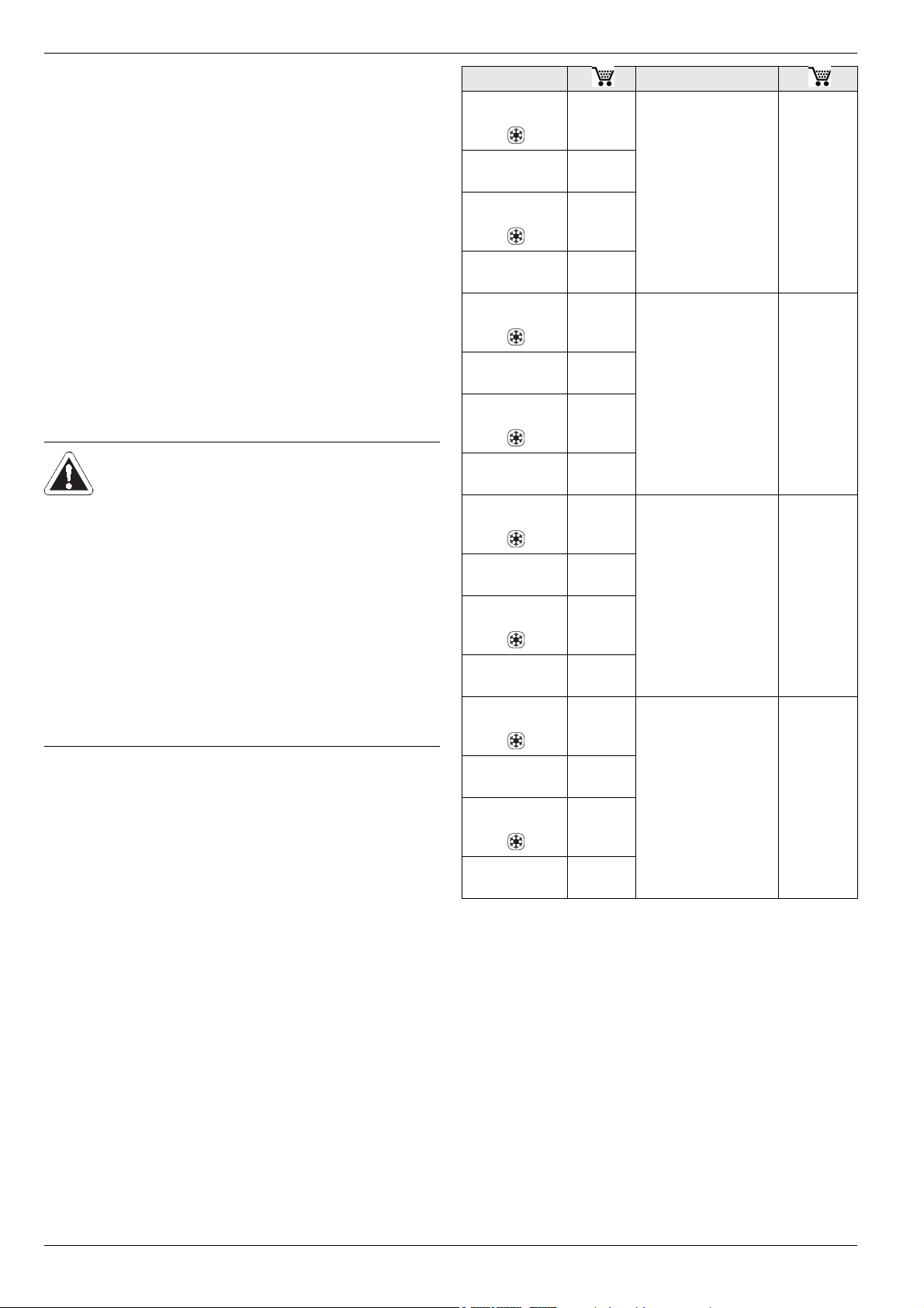
Internal unit External unit
HPSU compact
304 H/C DB-5 14 15 73
HPSU compact
304 H DB-5
HPSU compact
304 H/C Biv-5 14 15 77
HPSU compact
304 H Biv-5
HPSU compact
308 H/C DB-5
HPSU compact
308 H DB-5
HPSU compact
308 H/C Biv-5 14 15 78
HPSU compact
308 H Biv-5
HPSU compact
508 H/C DB-5 14 15 75
HPSU compact
508 H DB-5
HPSU compact
508 H/C Biv-5
HPSU compact
508 H Biv-5
HPSU compact
516 H/C DB-5 14 15 76
14 15 81
14 15 85
14 15 74
14 15 82
14 15 86
14 15 83
14 15 79
14 15 87
RRLQ004CAV3 14 51 51
RRLQ006CAV3
RRLQ008CAV3
RRLQ006CAV3
RRLQ008CAV3
14 51 52
14 51 53
14 51 52
14 51 53
2.3 Proper use
The ROTEX HPSU compact may only be used
for preparation of warm water, as a room heating
system, and depending on its design, as a room
cooling system.
The ROTEX HPSU compact must be installed,
connected and operated only according to the indications in this manual.
Only use of a suitable external unit approved by
ROTEX is permitted. The following combinations
are permissible in this respect:
HPSU compact
516 H DB-5
HPSU compact
516 H/C Biv-5
HPSU compact
516 H Biv-5
BIV - Additional heat exxchanger for the bivalent connection
* Not all the equipment mentioned here is offered in some countries because of
the various different country-specific connection conditions.
Tab. 2-1 Permissible combinations of ROTEX HPSU compact internal
units and ROTEX heat pump external units
14 15 84
14 15 80
14 15 88
RRLQ011CA(V3/W1)*
RRLQ014CA(V3/W1)*
RRLQ016CA(V3/W1)*
14 51 45/48
14 51 46/49
14 51 47/50
Any other use outside the intended use is considered as improper. The operator alone shall
bear responsibility for any resulting damage.
Use as intended also involves compliance with
maintenance and inspection conditions. Spare
parts must at least satisfy the technical requirements defined by the manufacturer. This is the
case, for example, with original spare parts.
6
FA ROTEX HPSU compact (V5.2) • 07/2017

2 x Safety
2.4 Instructions for operating safety
2.4.1 Before working on the hydraulic system
● Work on the ROTEX HPSU compact (such as
setup, servicing, connection and initial startup) is only to be carried out by persons who
are authorised and who have successfully
completed qualifying technical or vocational
training and who have taken part in advanced
training sessions recognised by the appropriate responsible authorities for the specific
activity. This, in particular, includes heating
specialists and climate control technicians
who have experience, as a result of their
technical training and their knowledge of the
subject, of proper and appropriate installation
and maintenance of heating, climate control
and cooling installations and heat pumps.
● Switch off the external main switch before
starting any work on the ROTEX HPSU
compact and secure it against unintentional
switch-on.
● Seals must not be damaged or removed.
● Make sure that the safety valves comply with
the requirements of EN 12828 when
connecting on the heating side, and with the
requirements of EN 12897 when connecting
on the domestic water side.
● Only original ROTEX replacement parts may
be used.
● When working on the hydraulics, you must first
drain the water or release the pressure using
the internal KFE valve. Otherwise hot water
can jet out under pressure and result in injury.
2.4.3 Working on cooling systems (heat pump)
The ROTEX HPSU compact requires fluorinated
greenhouse gas for its function.
For work on stationary refrigeration
systems (heat pumps) and air conditioning systems, proof of expertise is required in the European Community according to the F-Gases Directive (EC)
No. 303/2008.
– up to 3 kg coolant fill quantity:
Expert certificate category II
– 3 kg coolant fill quantity or over:
Expert certificate category I
● Always wear safety goggles and protective
gloves.
● When working on the refrigerant circuit,
ensure that the workplace is well ventilated.
● Never carry out work on the coolant circuit in
closed rooms or work pits.
● Do not let refrigerant come into contact with
open fire, embers or hot objects.
● Never allow refrigerant to escape into the
atmosphere (high pressure at the point of the
leak).
● When removing the service pipes from the
filling connections, never hold the connections
in the direction of your body. Residual refrigerant could escape.
● Components and spare parts must at least
satisfy the technical requirements defined by
the manufacturer.
2.4.2 Electrical installation
● Electrical installation may be carried out only
by electrical engineers and in compliance with
the valid electro-technical guidelines as well as
the regulations of the relevant energy supply
company (EVU).
● Compare the mains voltage (~230 V, 50 Hz or
~400 V, 50 Hz) indicated on the type plate with
the supply voltage before connecting to the
mains.
● Before beginning work on live parts,
disconnect all of the systems circuits from the
power supply (switch off main switch,
disconnect fuse) and secure against unintentional restart.
● Equipment covers and service panels must be
replaced as soon as the work is completed.
FA ROTEX HPSU compact (V5.2) • 07/2017
2.4.4 Site of installation
For safe and fault-free operation, it is necessary
that the installation location of the ROTEX HPSU
compact fulfils certain criteria. Related information can be found in chapter 4.2.
Information on the installation site of other components can be found in the associated documentation supplied with them.
7

2 x Safety
2.4.5 Heating system and sanitary connection
● Create a heating system according to the
safety requirements of EN 12828.
● With sanitary connection, you must observe;
– EN 1717 - Protection of domestic water
from contamination in domestic water
installations and general requirements concerning safety equipment for the prevention
of domestic water contamination by backflow
– EN 806 - Technical regulations for domes-
tic water installations
– and, in addition, the country-specific legal
regulations.
The connection of a solar installation, an electric
heating rod or an alternative heat generator may
cause the storage temperature to exceed 60 °C.
● For this reason you should fit scalding
protection (e.g. VTA32 15 60 15 + Screw
connection set 1" 15 60 16).
If the ROTEX HPSU compact is connected to a
heating system with steel pipes, radiators or nondiffusion-proof floor heating pipes, slurry and
swarf could enter the hot water storage tank and
cause blockages, local overheating or corrosion.
● To prevent possible damage, fit a dirt filter or
sludge separator into the heating return flow
of the system.
– SAS 1 ( 15 60 21)
● The dirt filter must be cleaned at regular
intervals.
2.4.6 Requirements for the heating water
Observe the current technological regulations to
prevent corrosion products and deposits.
Minimum requirements regarding the quality
of filling and supplementary water:
– Water hardness (calcium and magnesium,
calculated as calcium carbonate):
≤ 3 mmol/l
– Conductivity: ≤ 1500 (ideal ≤ 100) μS/cm
–Chloride: ≤ 250 mg/l
– Sulphate: ≤ 250 mg/l
– pH value (heating water): 6,5 - 8,5
Using filling water and top-up water which does
not meet the stated quality requirements can
cause a considerably reduced service life of the
equipment. The responsibility for this is entirely
that of the operator.
2.4.7 Operation
The ROTEX HPSU compact:
● Do not operate until all installation and
connection work is completed.
● Only operate with a completely full storage
tank (Level indicator) and heating circuit.
● Operate at a maximum pressure of 3 bar.
● Only connect with a pressure reducer on the
external water supply (supply line).
● Only operate the with the specified quantity of
refrigerant and the type of refrigerant
specified.
● Only operate if the protective cover is
installed.
The prescribed maintenance intervals must
be maintained and the inspection work must
be carried out.
8
FA ROTEX HPSU compact (V5.2) • 07/2017

2.4.8 Instructing the user/owner
● Before you hand over the ROTEX HPSU
compact, explain to the user/owner how to
operate and check the system.
● Hand over the technical documentation (this
document and all supporting documents) to
the user and advise him that these documents
must be made available at all times and be
stored in the immediate vicinity of the unit.
● Make a record of the handover by filling out
and signing the installation and instruction
forms jointly with the user/owner.
2 x Safety
FA ROTEX HPSU compact (V5.2) • 07/2017
9
3 x Product description
3 Product description
3.1 Design and components
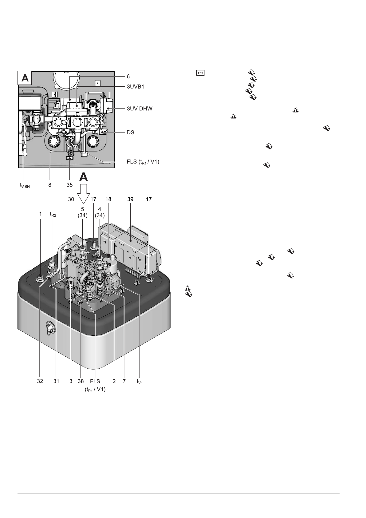
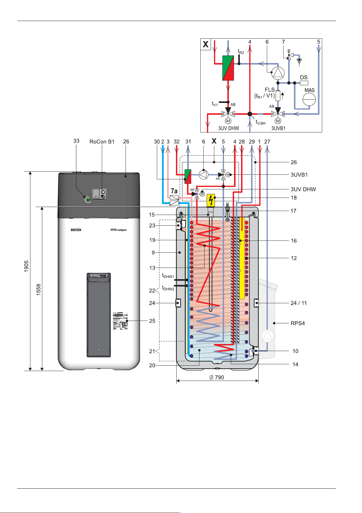
3.1.1 Top of unit
1 Solar - flow (1" IG)
2 Cold water flow (1" AG)
3 Hot water flow (1" AG)
4 Heating flow (1" AG)*
5 Heating return (1" AG)*
6 Circulation pump
7 Safety-pressure relief valve (heating circuit)
8 Automatic vent
17 Fill level indicator (tank water)
18 Connection for electrical Backup Heater BUxx (R 1½" IG)
(Accessory)
30 Plate heat exchanger (PWT)
31 Connection refrigerant fluid line
ROTEX HPSU compact 30x/508: Cu Ø 6.4 mm (1/4"),
ROTEX HPSU compact 516: Cu Ø 9.5 mm (3/8")
32 Connection to coolant gas line
Cu Ø 15,9 mm (5/8")
34 Ball cock (heating circuit)*
35 Combined filling and draining valve (heating circuit)
37 Storage tank temperature sensor t
38 Connection diaphragm expansion vessel
39 Controller housing with elect. terminal strip
DHW1
and t
DHW2
3UVB1
3-way diverter valve (internal heat generator circuit)
3UV DHW
DS Pressure sensor
FLS (t
tR2Return flow temperature sensor
t
V1
t
V, BH
AG Male thread
IG Female thread
* Ball cock (1" IG) is supplied with the equipment
Fig. 3-1 Structure and constituents ROTEX HPSU compact DB
3-way diverter valve (hot water / heating)
/ V1)
R1
Return flow temperature and flow sensor
Inflow temperature sensor
Flow temperature sensor Backup Heater
Safety devices
Observe tightening torque!
(top side of device)
10
FA ROTEX HPSU compact (V5.2) • 07/2017
3 x Product description
3.1.2 Equipment external and internal structure ROTEX HPSU compact 304/308 DB
Fig. 3-2 Structure and constituents ROTEX HPSU compact 304/308 DB (External appearance and internal structure)
Designations of key see tab. 3-1
FA ROTEX HPSU compact (V5.2) • 07/2017
11
3 x Product description
3.1.3 Equipment external and internal structure ROTEX HPSU compact 304/308 BIV
Fig. 3-3 Structure and constituents ROTEX HPSU compact 304/308 BIV (External appearance and internal structure)
Designations of key see tab. 3-1
12
FA ROTEX HPSU compact (V5.2) • 07/2017
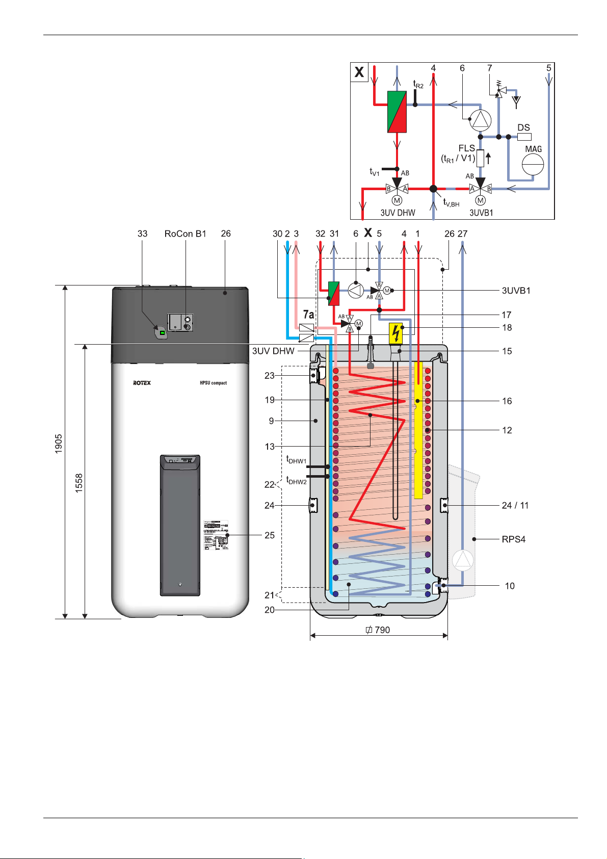
3 x Product description
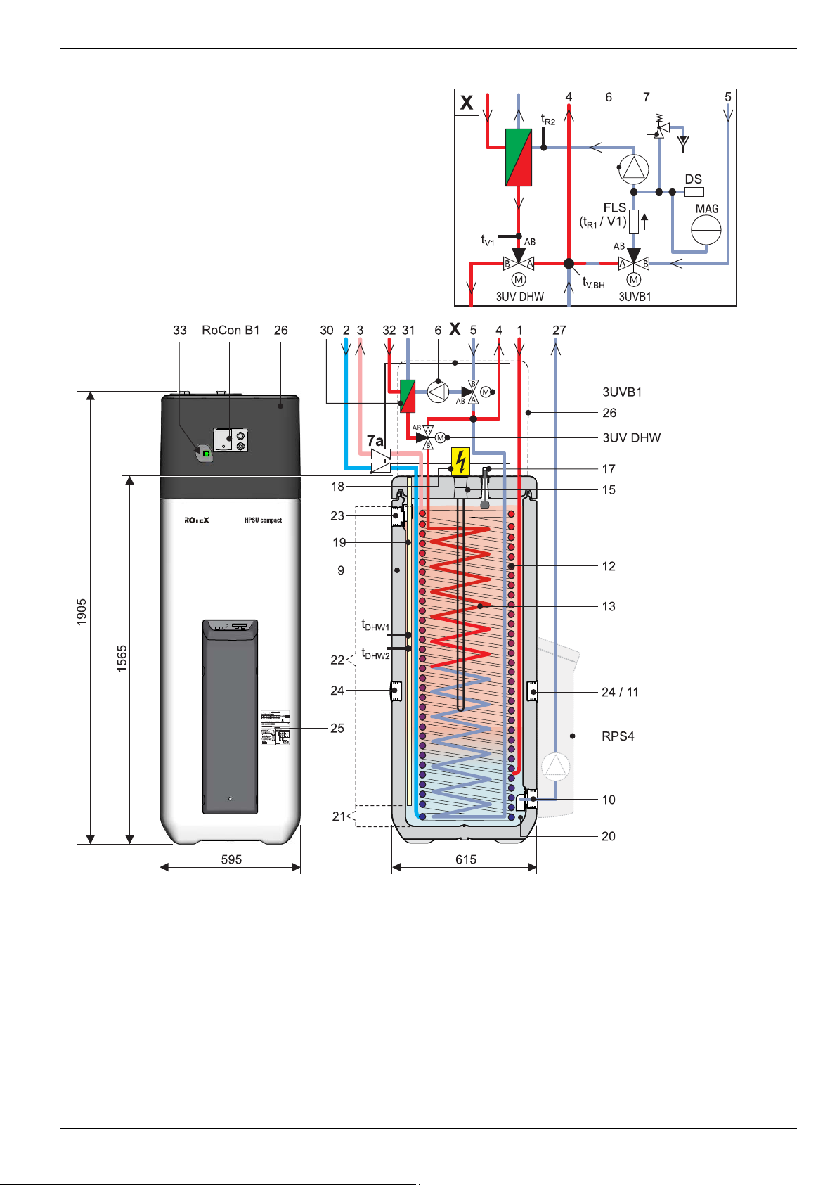
3.1.4 Equipment external and internal structure ROTEX HPSU compact 508/516 DB
Fig. 3-4 Structure and constituents ROTEX HPSU compact 508/516 DB (External appearance and internal structure)
Designations of key see tab. 3-1
FA ROTEX HPSU compact (V5.2) • 07/2017
13
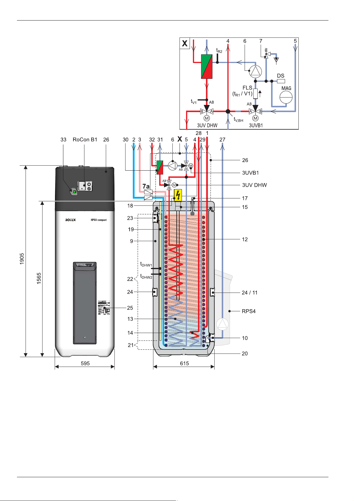
3 x Product description
3.1.5 Equipment external and internal structure ROTEX HPSU compact 508/516 BIV
Fig. 3-5 Structure and constituents ROTEX HPSU compact 508/516 BIV (External appearance and internal structure)
14
Designations of key see tab. 3-1
FA ROTEX HPSU compact (V5.2) • 07/2017
3 x Product description
1 Solar - flow or connection for addition-
al heat source(1" IG)
2 Cold water flow (1" AG)
3 Hot water flow (1" AG)
4 Heating flow (1" AG)*
5 Heating return (1" AG)*
6 Circulation pump
7a Recommended accessories:
Non-return valves (2 pcs.), 16 50 70
9 Storage tank (double walled jacket made
of polypropylene with PUR hard foam heat
insulation)
10 Filling and drainage connection or
Solar - return flow connection
11 Mount for solar controller or handle
12 Heat exchanger (stainless steel) for drink-
ing water heating
13 Heat exchanger (stainless steel) for stor-
age tank charging or heating support
14 Heat exchanger (stainless steel) for pres-
surised solar storage tank charging
15 Connection for optional electrical Backup
Heater (R 1½" IG)
16 Solar inflow layering pipe
17 Fill level indicator (tank water)
18 Optional: Electrical backup heater
(BUxx)
19 Submersible sensor sleeve for storage
tank temperature sensor t
20 Unpressurised storage tank water
21 Solar zone
22 Hot water zone
23 Safety overflow connection
24 Mount for handle
25 Type plate
26 Protective cover
27 Solar - return
28 Solar - feed (3/4" IG + 1" AG)
(only type … Biv)
29 Solar - return flow (3/4" IG + 1" AG)
(only type … Biv)
30 Panel heat exchanger
31 Fluid line for connection of refrigerant
fluid
ROTEX HPSU compact 30x/508:
Cu Ø 6.4 mm (1/4"),
ROTEX HPSU compact 516:
Cu Ø 9.5 mm (3/8")
32 Connection to coolant gas line
Cu Ø 15,9 mm (5/8")
3UVB1
3-way diverter valve (internal heat genera-
tor circuit)
3UV DHW
3 way diverter valve (hot water/heating)
DHW1
and t
DHW2
DS Pressure sensor
FLS (t
t
tR2Return flow temperature sensor
tV1Inflow temperature sensor
t
RoCon B1
RPS4
AG Male thread
IG Female thread
* Ball cock (1" IG) is supplied with the equip-
/ V1)
R1
Return flow temperature and flow sensor
, t
DHW1
DHW2
Storage tank temperature sensor
V, BH
Flow temperature sensor Backup
Heater
Operating section ROTEX HPSU compact
control unit
Optional: ROTEX Solar regulation
and pump unit
Safety devices
Observe tightening torque!
ment
Tab. 3-1 Legend from fig. 3-2 to fig. 3-5
FA ROTEX HPSU compact (V5.2) • 07/2017
15

4 x Set-up and installation
4 Set-up and installation
WARNING
Cooling systems (heating pumps), climate control systems and heating devices that have
been set up and installed incorrectly can both endanger life and health of people and be impaired in their function.
● Work on the ROTEX HPSU compact (such as setup, servicing, connection and initial
start-up) is only to be carried out by persons who are authorised and who have successfully completed qualifying technical or vocational training and who have taken part in
advanced training sessions recognised by the relevant responsible authorities for the
specific activity. These include in particular certified heating engineers, qualified
electricians and HVAC specialists, who because of their professional training and
expert knowledge, have experience in the professional installation and maintenance of
heating, cooling and air conditioning systems and heat pumps.
16
FA ROTEX HPSU compact (V5.2) • 07/2017
4.1 Dimensions and connections
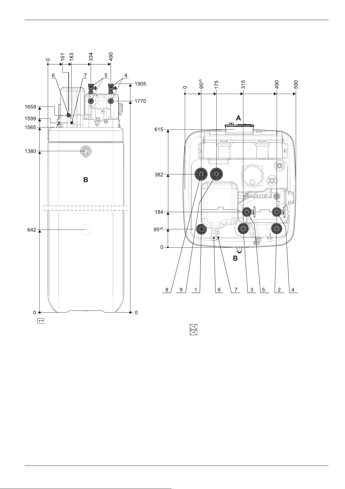
4.1.1 ROTEX HPSU compact 304/308
4 x Set-up and installation
1 Solar - feed
2 Cold water
3 Hot water
4 Heating feed
5 Heating return flow
6 Connection coolant gas line
Fig. 4-1 Connections and dimensions ROTEX HPSU compact 304/308 (in general)
7 Connection coolant fluid line
8 Solar - feed (only type …Biv)
9 Solar - return flow (only type …Biv)
A Front
BBack
FA ROTEX HPSU compact (V5.2) • 07/2017
17
4 x Set-up and installation
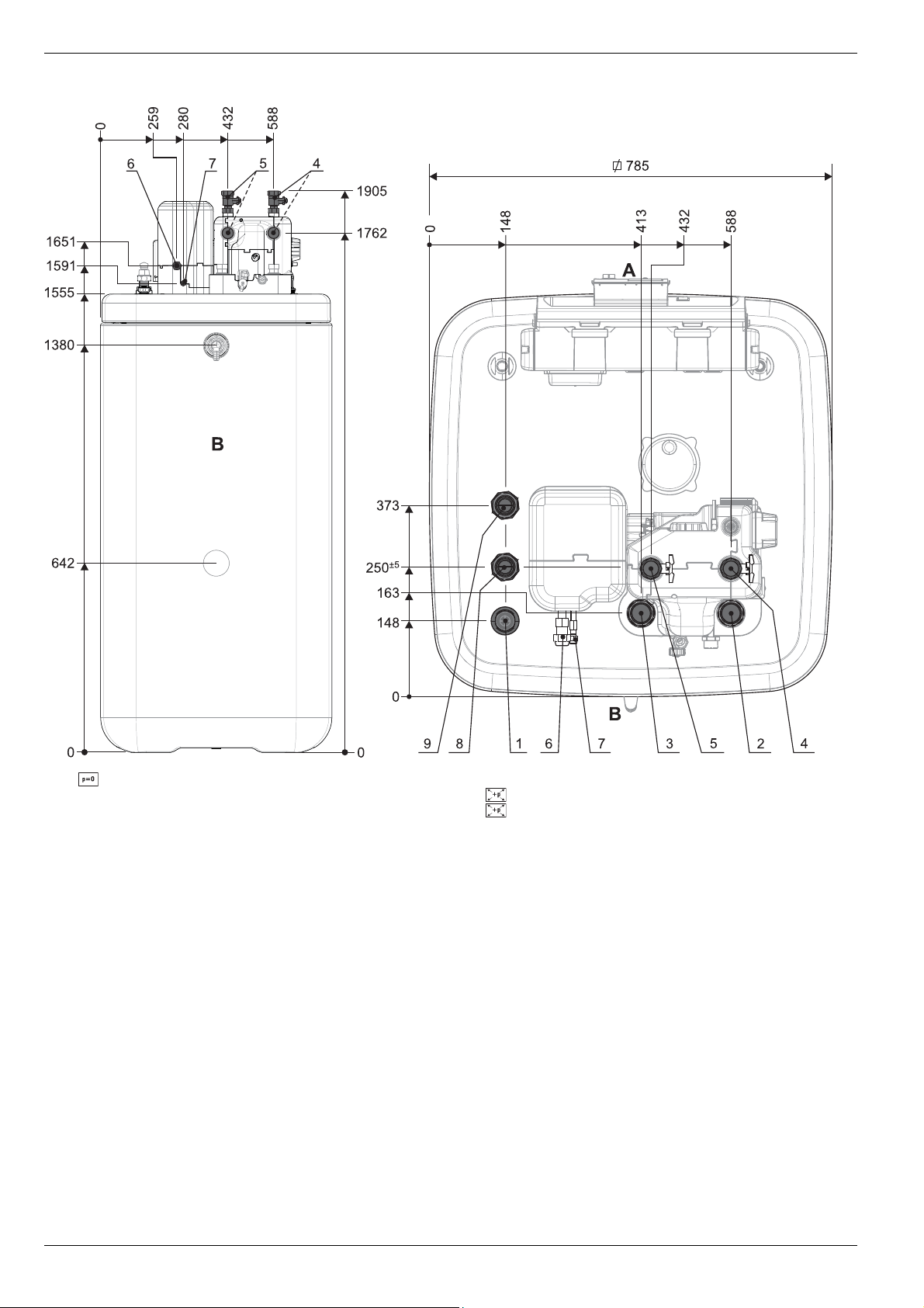
4.1.2 ROTEX HPSU compact 508/516
1 Solar - feed
2Cold water
3 Hot water
4 Heating feed
5 Heating return flow
6 Connection coolant gas line
Fig. 4-2 Connections and dimensions ROTEX HPSU compact 508/516 (in general)
7 Connection coolant fluid line
8 Solar - feed (only type …Biv)
9 Solar - return flow (only type …Biv)
A Front
BBack
18
FA ROTEX HPSU compact (V5.2) • 07/2017
4 x Set-up and installation
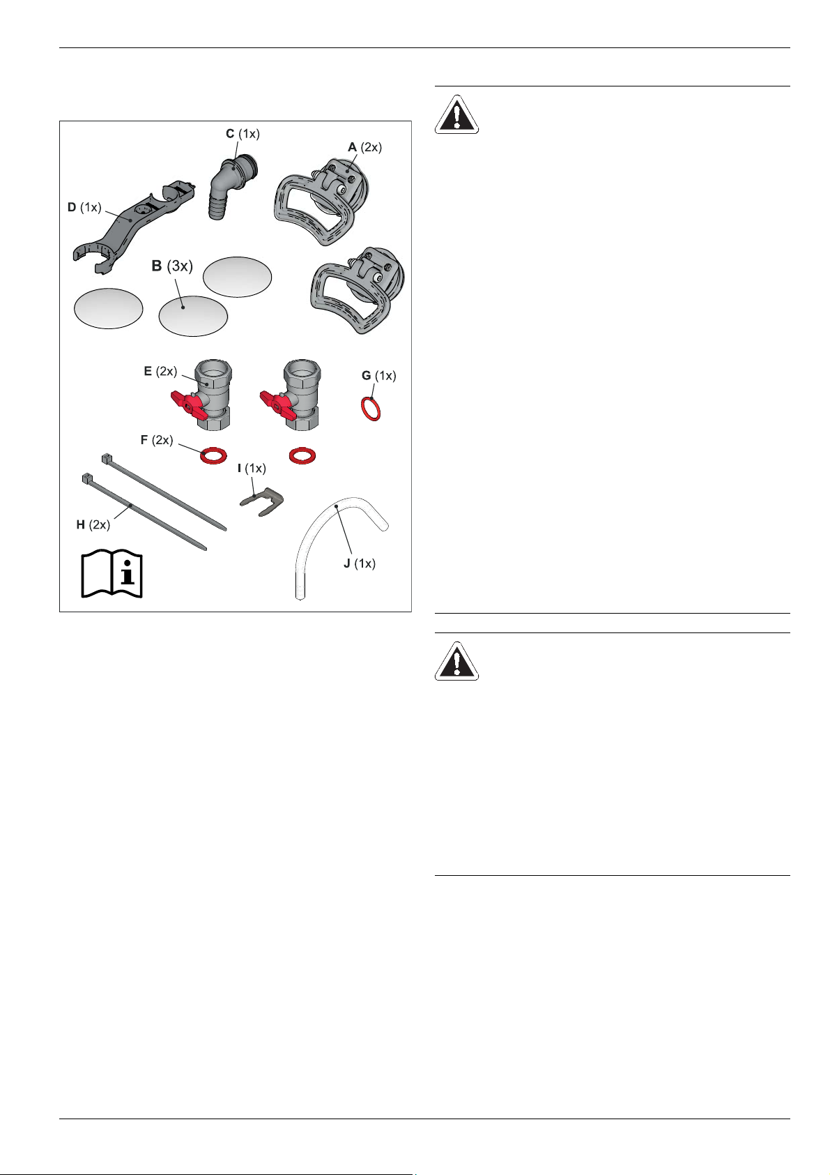
4.1.3 Scope of delivery
– ROTEX HPSU compact
– Bag of accessories (see fig. 4-3)
4.2 Set-up
CAUTION!
● Only erect the ROTEX HPSU
compact when a sufficient ground
load-bearing capacity, of
1050 kg/m² plus safety margin, has
been assured. The ground must be
flat and level.
● Outdoor installation is not permitted.
● Erection in explosion-risk environ-
ments is not permitted.
● The electronic control system must
not be subjected to atmospheric
factors under any circumstances.
● The storage tank must not be
exposed to continuous direct solar
radiation, since the UV radiation and
weather-influences will damage the
plastic.
● The ROTEX HPSU compact must be
installed in a manner protected from
frost.
● Make sure that the supply company
does not provide corrosive
domestic water.
– Suitable water treatment may be
required.
A Handles (only required for
transport)
B Cover screen
C Hose connection piece for
safety overflow
D Spanner
Fig. 4-3 Contents of bag of accessories
EBall cock
F Flat seal
GO-ring
H Tie wraps
I Plug bracket
J Venting tube
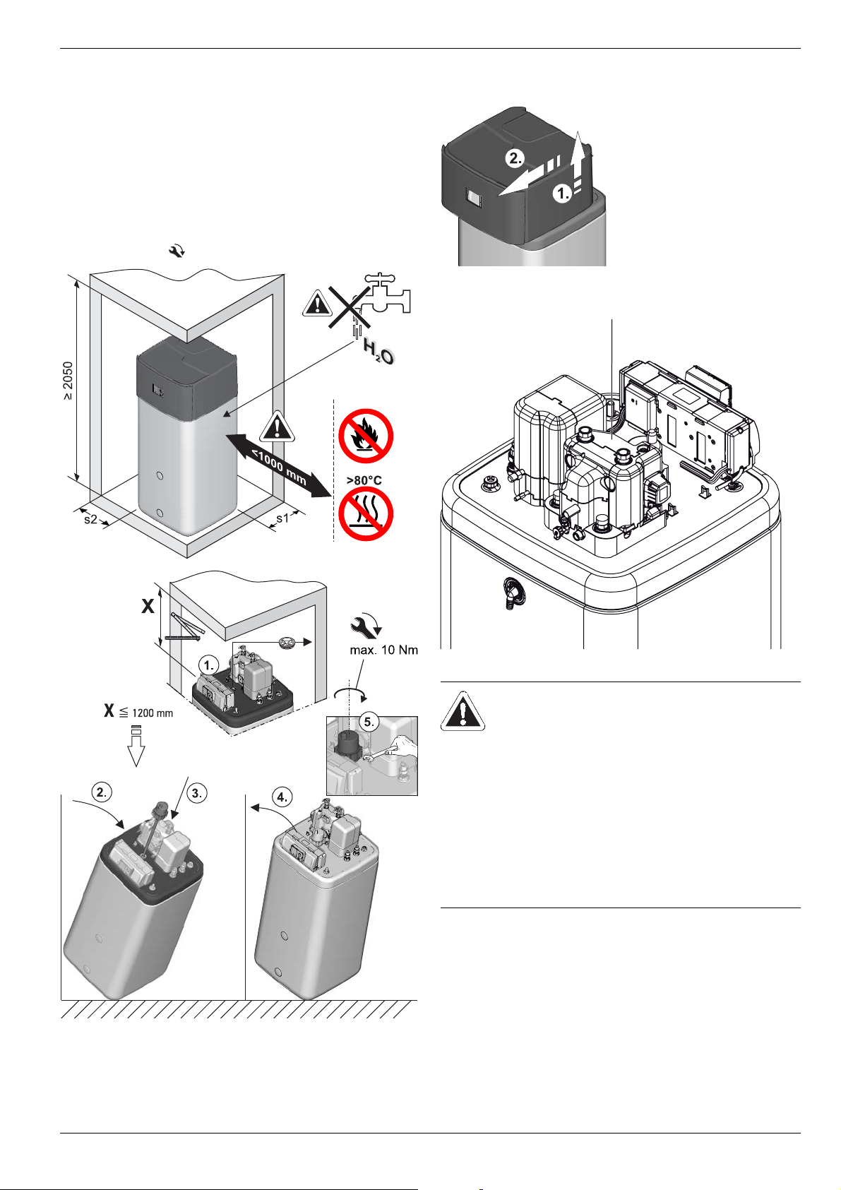
WARNING!
The plastic wall of the storage tank on
the ROTEX HPSU compact may melt
due to the effects of external heat
(>80 °C) and, in the extreme case, can
catch fire.
● Erect the ROTEX HPSU compact
only at a minimum distance of 1 m to
other heat sources (>80 °C) (e.g.
electric heater, gas heater, chimney)
and flammable materials.
FA ROTEX HPSU compact (V5.2) • 07/2017
19
4 x Set-up and installation
CAUTION!
ROTEX HPSU compact is not erected
adequately lower the flat solar panels
(the top edge of the of the storage tank is
higher than the bottom edge of the solar
panels), the unpressurised solar system
in the outdoor area will be unable to
drain completely.
● Erect the ROTEX HPSU compact with
a DrainBack solar connection at a
sufficient depth to the flat solar panels
(observe the minimum gradient in the
solar connecting lines).
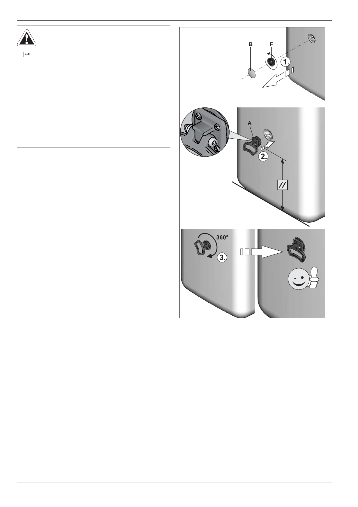
● Remove packing and dispose of it in an environment-friendly
manner.
● Remove the cover plates on the storage tank (fig. 4-4, item B)
and unscrew the threaded pieces (fig. 4-4, item F) from the
apertures on which the handles are to be mounted (fig. 3-2 to
fig. 3-5, item 24).
● Screw handles (fig. 4-4, item A) into the threaded holes that
are now free.
20
A Handle
B Cover screen
Fig. 4-4 Attach handles
FA ROTEX HPSU compact (V5.2) • 07/2017
F Threaded piece
4 x Set-up and installation
A
● Install the ROTEX HPSU compact at the installation site.
– Recommended clearances (fig. 4-5):
To the wall: (s1) ≥ 100 mm, (s2) ≥ 500 mm.
From the ceiling (X): ≥ 1200 mm, minimum 480 mm.
– Carefully transport the ROTEX HPSU compact, use the
handles.
– When setting up the unit in a cabinet, behind panels or in
other restricted conditions, sufficient ventilation (e.g.,
using ventilation gratings) must be ensured.
● If necessary, install the optional Backup Heater (BUxx) in the
ROTEX HPSU compact (
Observe the assembly and operating manual supplied with
the accessory ( for tightening torque see chapter 10.3).
fig. 4-5).
4.3 Remove cover hood and heat insulation
● Lift the cover hood at the back and remove to the front.
Fig. 4-6 Removing the protective cover
Fig. 4-5 Layout (shown on ROTEX HPSU compact 508/516 with incor-
poration of the optional Backup Heater)
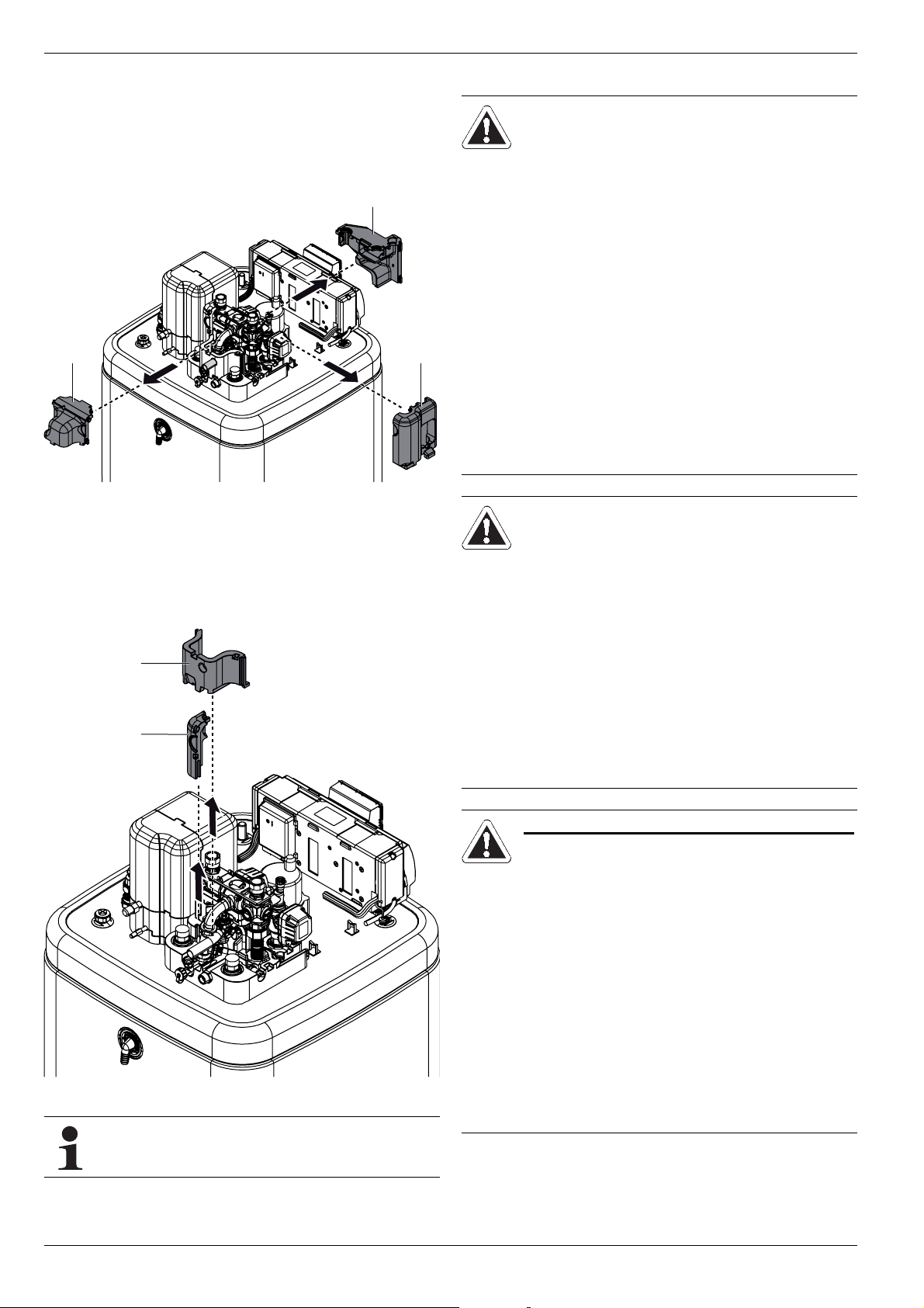
Fig. 4-7 ROTEX HPSU compact without cover hood
CAUTION!
The thermal insulation (fig. 4-7, item A)
consists of pressure sensitive shaped
EPP components that can easily be
damaged by inappropriate handling.
● Carry out removal of the thermal
insulation only in the sequence and in
the directions quoted below.
● Do not use force.
● Do not use tools.
FA ROTEX HPSU compact (V5.2) • 07/2017
21
4 x Set-up and installation
A
B
C
A
B
● Remove the top thermal insulation in the following order:
– Pull away the side insulation element (fig. 4-8, item A)
horizontally.
– Pull away the rear insulation element (fig. 4-8, item B) hor-
izontally.
– Pull away the front insulation element (fig. 4-8, item C)
horizontally.
Fig. 4-8 Removing top thermal insulation
● If required: Remove the bottom thermal insulation in the
following order:
– Pull away the side insulation element (fig. 4-9, item A) ver-
tically.
– Pull away the rear insulation element (fig. 4-9, item B) ver-
tically.
4.4 Water connection
CAUTION!
If the ROTEX HPSU compact is connected to a heating system with steel
pipes, radiators or non-diffusion-proof
floor heating pipes, slurry and swarf
could enter the hot water storage tank
and cause blockages, local over-
heating or corrosion.
● Flush the feed pipes before filling the
heat exchanger.
● Rinse out the heat distribution
network (in the existing heating
system).
● Install the dirt filter or sludge
separator into the heating return flow
(see chapter 2.4.5).
CAUTION!
If the ROTEX HPSU compact is connected to a cold water line, where steel
pipes are used, chips can enter the
special steel corrugated pipe heat exchanger and remain there. This can lead
to contact corrosion damage and subsequently to leakage.
Fig. 4-9 Removing bottom thermal insulation
Installing the thermal insulation is carried out in the
reverse order.
● Flush the feed pipes before filling the
heat exchanger.
● Install contamination filter in the cold
water feed (see chapter 2.4.5).
ONLY ROTEX HPSU COMPACT …BIV
CAUTION!
If the heat exchanger for charging the
pressurised solar system (fig. 4-1 /
fig. 4-2, item 8+9) has an external
heating unit (e.g. wood-burning boiler)
connected to it, an excessive flow temperature at these connections can
damage or destroy the ROTEX HPSU
compact.
● The feed flow temperature of the
external heater should be limited to
max. 95 °C.
22
FA ROTEX HPSU compact (V5.2) • 07/2017
4 x Set-up and installation
In accordance with EN 12828 you must install a safety
valve at or in the immediate vicinity of the heat
exchanger, with which you can limit the maximum per
missible operating pressure in the heating system.
There should be no hydraulic blocking elements
between the heat generator and the safety valve.
Any steam or heating water which may escape must be
diverted by a suitable blow-off line with constant gradi
ent in a frost-protected, safe and observable manner.
A diaphragm expansion vessel of adequate dimensions
and pre-set for the heating system must be connected
to the ROTEX HPSU compact. There should be no
hydraulic blocking elements between the heat genera
tor and the diaphragm expansion vessel.
ROTEX recommends integrating a mechanical
manometer for the filling of the heating system.
● For drinking water lines, comply with the EN 806 and
DIN 1988 stipulations.
● To avoid a circulation line, install ROTEX HPSU compact
close to the draw-off location. If a circulation line is absolutely
essential, it must be installed in accordance with the
schematics in
chapter 9 "Hydraulic system connection".
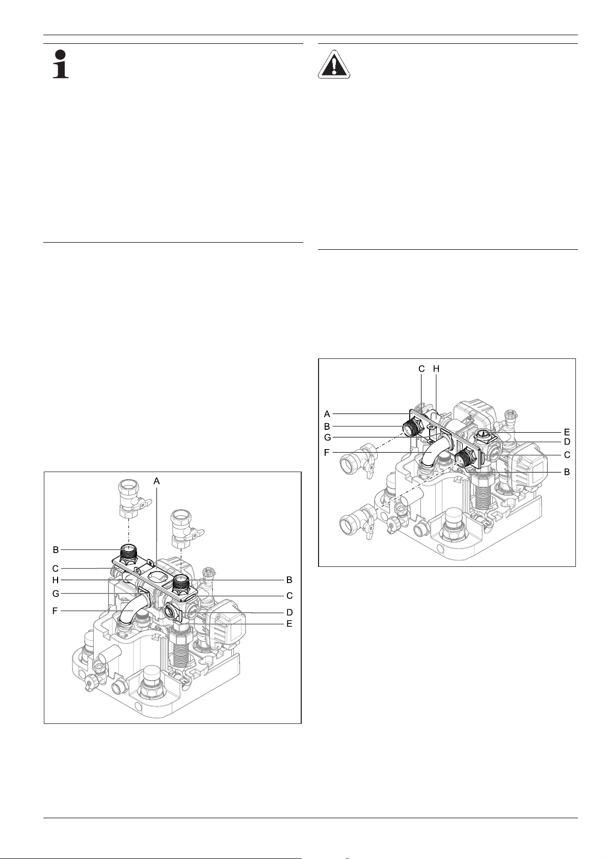
4.4.1 Aligning the connections of the heating feed
and return flow
CAUTION!
-
When working on the hydraulics you
must take care of the mounting position
of the O-rings to prevent damage to the
O-rings and consequent leaks.
-
● Always place O-rings on the part to be
inserted after a plug connection has
been removed or before it is installed.
● Connection of heating lines by plug
-
connection must be without tension.
Establish suitable tension relief particularly for connection with flexible lines
(not breathable!).
● Remove retainer plate (fig. 4-10, item A).
● Pull off the plug bracket on the closing plug (fig. 4-10, item D).
● Pull out the closing plug (fig. 4-10, item E).
● Rotate the angular piece (fig. 4-10, item H) by 90° to the back.
● Pull off the plug bracket on the elbow (fig. 4-10, item G).
● Pull the elbow (fig. 4-10, item F) carefully to the rear out of its
horizontal mount so that the retainer plate (fig. 4-11, item A)
can be inserted in the gap vertically.
The connections for the heating feed and return flow can be directed out of the unit upwards or downwards in order to adapt to
the on-site conditions in the most optimum manner.
The unit is delivered with the connections exiting upwards as
standard. In order to direct the connections out from the back of
the unit you must carry out the following conversion steps:
● Remove the cover hood and the upper thermal insulation
(see chapter 4.3).
Fig. 4-11 Heating feed and return flow connections aligned to the rear
● Slide the retainer plate between the elbow and its horizontal
mount and insert the elbow (fig. 4-11, item F) back in its
mount through the central hole in the retainer plate.
Fig. 4-10 Heating feed and return flow connections aligned upwards
● Pull off both the plug brackets on the connection couplings
(fig. 4-10, item C).
● Pull off both connection couplings (fig. 4-10, item B).
FA ROTEX HPSU compact (V5.2) • 07/2017
23
4 x Set-up and installation
A
A
CAUTION!
If the plug brackets are not inserted
properly, the couplings can come loose
in their mounts which may result in high
levels of fluid escape and continuous
fluid escape.
● Before plugging in a plug bracket,
make sure that the plug bracket
engages in the groove in the coupling.
To do this, insert the coupling into the
mount until the groove becomes
visible through the plug bracket
mount.
● Insert the plug bracket up to the stop.
● Secure the elbow back into its mount with plug bracket
(fig. 4-11, item G).
● Insert both connection couplings (fig. 4-11, item B) through
the retainer plate in the side mounts.
● Secure both connection couplings in their mounts with the
plug brackets (fig. 4-11, item C).
● Insert the closing plug (fig. 4-11, item E) in the top mount.
● Secure the closing plug with the plug bracket (fig. 4-11,
item D).
● Cut out the side transit points in the thermal insulation
(fig. 4-12, item A) using a suitable tool.
● Establish hydraulic connections at the ROTEX HPSU
compact.
– Position and dimensions of the heating connections to be
taken from fig. 4-1 / fig. 4-2 and from tab. 3-1.
– Pay attention to the stipulated tightening torque
(see chapter 10.3 "Tightening torque").
– Design the lines as such that the sound attenuation cowl
can be applied without any problem following assembly.
– Connect the water for filling or refilling the heating system
as specified by EN 1717 to avoid contamination of drinking water by backwash.
● Connect a drain line to the safety overpressure valve and
connect a diaphragm drain container in accordance with
12828.
EN
– Check the seating of the drain hose on the overpressure
valve.
– If required, attach your own hose and route accordingly.
● Carefully insulate pipe lines against heat loss and so as to
avoid the formation of condensation (insulation thickness at
least 20
– Water shortage protection: The pressure and temperature
monitoring of the control unit safely switches off the ROTEX
HPSU compact in the event of a water shortage. No addi
tional water shortage protection is needed in the construction.
– Avoid damages caused by deposits and corrosion:
Observe the relevant regulations of technology to prevent
creation of corrosion products and deposits.
Minimum requirements regarding the quality of filling and supplementary water:
– Water hardness (calcium and magnesium, calculated as
– Conductivity: ≤ 1500 (ideal ≤ 100) μS/cm
– Chloride: ≤ 250 mg/l
– Sulphate: ≤ 250 mg/l
– pH value (heating water): 6,5 - 8,5
mm).
-
calcium carbonate): ≤ 3 mmol/l
Fig. 4-12 Thermal insulation cut-out
4.4.2 Connecting hydraulic lines
Requirement: Optional accessories (e.g. Solar, backup heater)
mounted on the ROTEX HPSU compact according to the specifi
cations of the instructions included.
● Check cold water pressure (maximum 6 bar).
– At higher pressure in the drinking water line, a pressure
reducer must be installed.
In the case of filling and top-up water with a high overall hardness
or other properties that deviatte from the minimum requirements,
measures for the desalination, softening, hardness stabilisation
or other suitable conditioning measures are required to maintain
the required water quality.
WARNING!
There is a danger of scalding at hot
water temperatures over 60
°C. This is
possible, when solar energy is used, with
a connected external heating device,
when the Legionella protection is acti
vated or when the domestic hot water
target temperature is set higher than
-
60 °C.
● Install a scald protection (domestic
hot water mixing unit (e.g. VTA32
15 60 15).
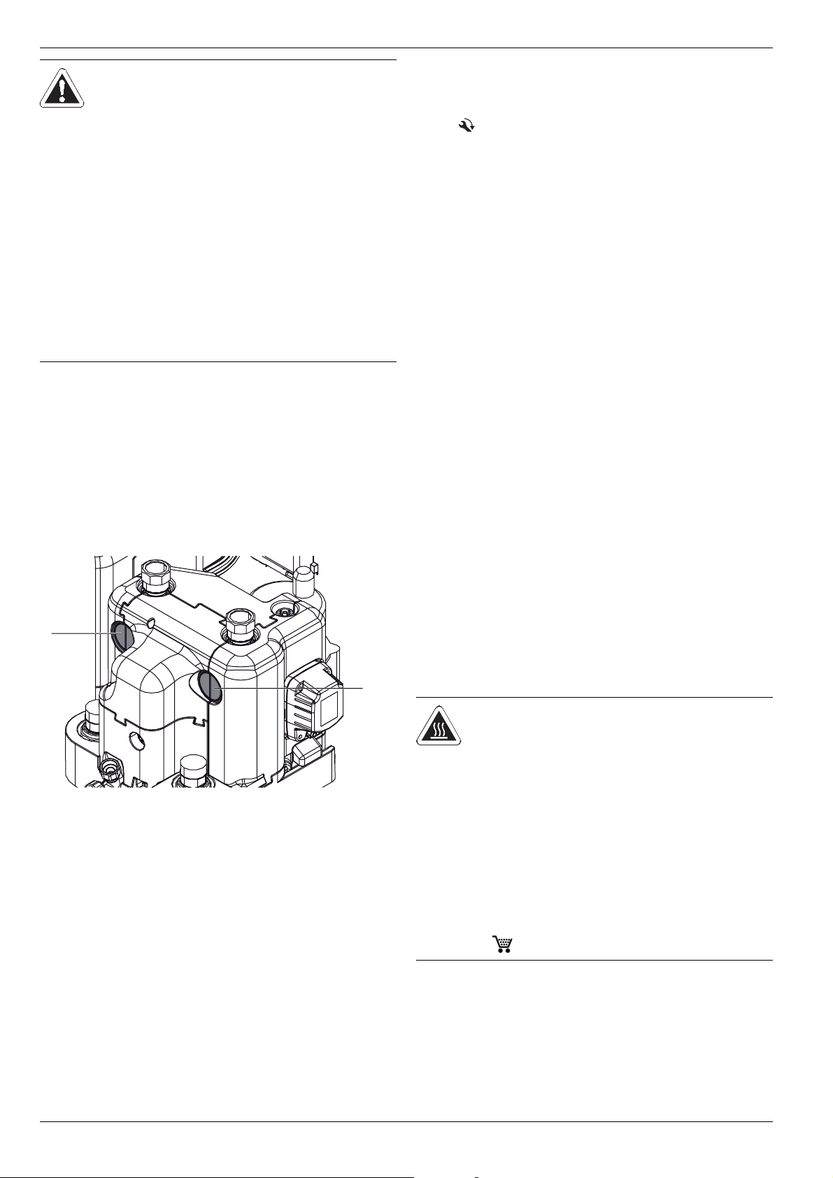
● Connect the drain hose to the connection piece for the safety
overflow (
– Use transparent drain hose (draining water must be visi-
– Connect the drain hose to an adequately dimensioned
– Drain should not be lockable.
fig. 3-2 to fig. 3-5, item 23).
ble).
waste water installation.
24
FA ROTEX HPSU compact (V5.2) • 07/2017
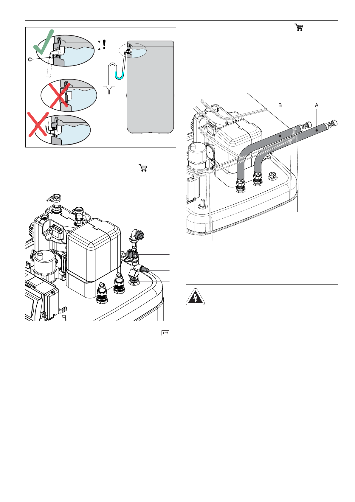
Fig. 4-13 Installation of drain hose at safety overflow
A
D
B
C
4.4.3 Installation of DB connection kit ( 141590)
The optional DB connection kit provides improved accessibility
for connecting the DrainBack line (solar feed).
4 x Set-up and installation
4.4.4 Installation of P connection kit ( 141589)
The optional P connection kit for Biv device types provides better
access for connecting the feed and return flow of a pressurised
solar system or another external heat generator to the storage
tank. The kit contains two thermally insulated corrugated pipes
that are connected to the connections on the storage tank with a
union nut. At the other end of the corrugated pipe there is an
adapter for each of the various different connection sizes of the
feed and return flow line.
A DB line connection (solar
feed)
B FlowSensor (not included in
the DB connection kit, but in
cluded in RPS4)
Fig. 4-14 DB connection kit
C Flow limiter (FlowGuard)
D Solar feed connection on
the storage tank
-
A Flow connection (red)
B Return flow connection (blue)
Fig. 4-15 P connection kit for Biv equipment types
4.5 Electrical connection
WARNING!
Touching live parts can result in an
electric shock and lead to potentially
fatal injuries and burns.
● Before beginning work on live parts,
disconnect all of the systems circuits
from the power supply (switch off
main switch, disconnect fuse) and
secure against unintentional restart.
● The electrical connection and working
on the electrical components should
only be performed by electrical
engineers in compliance with valid
standards and guidelines as well as
the specifications of the energy
supply company.
● The equipment covers and maintenance opening covers must be refitted immediately after completion of
the work.
FA ROTEX HPSU compact (V5.2) • 07/2017
25

4 x Set-up and installation
CAUTION!
In the controller housing of the
ROTEX HPSU compact, in continuous
running, elevated temperatures can be
generated. This can result in currently-
carrying wires from reaching higher
temperatures during operation due to
self-heating. For this reason, these lines
need to have a continuous use temperature of 90 °C.
● For the following connections, use
only cables with a long-term use
temperature ≥90 °C:
– Exterior heat pump unit
– Optional: Electrical Backup Heater
(BUxx)
26
FA ROTEX HPSU compact (V5.2) • 07/2017