

Daikin FXLQ25MAVE, FXLQ32MAVE, FXLQ40MAVE, FXLQ20MAVE, FXLQ-MAVE Series Technical Data Manual
...
technical data
air conditioning systems
Floor Standing Unit
FXLQ-MAVE
technical data
air conditioning systems
Floor Standing Unit
FXLQ-MAVE

• Indoor Units • FLOOR STANDING UNIT • FXLQ-MAVE
2
•VRV® Systems • Indoor Units

• Indoor Units • FLOOR STANDING UNIT • FXLQ-MAVE
TABLE OF CONTENTS
FXLQ-MAVE
1 Specifications . . . . . . . . . . . . . . . . . . . . . . . . . . . . . . . . . . . . . . . . . . . . . . . . . . . . . . . 3
Technical Specifications . . . . . . . . . . . . . . . . . . . . . . . . . . . . . . . . . . . . . . . . . . . . . 3
Electrical Specifications (50Hz) . . . . . . . . . . . . . . . . . . . . . . . . . . . . . . . . . . . . . 4
Electrical Specifications (60Hz) . . . . . . . . . . . . . . . . . . . . . . . . . . . . . . . . . . . . . 4
2 Safety device settings . . . . . . . . . . . . . . . . . . . . . . . . . . . . . . . . . . . . . . . . . . . . . 5
3 Options . . . . . . . . . . . . . . . . . . . . . . . . . . . . . . . . . . . . . . . . . . . . . . . . . . . . . . . . . . . . . . 5
4 Control systems . . . . . . . . . . . . . . . . . . . . . . . . . . . . . . . . . . . . . . . . . . . . . . . . . . . . 6
5 Capacity tables . . . . . . . . . . . . . . . . . . . . . . . . . . . . . . . . . . . . . . . . . . . . . . . . . . . . . 7
Cooling capacity tables . . . . . . . . . . . . . . . . . . . . . . . . . . . . . . . . . . . . . . . . . . . . . . 7
Heating capacity tables . . . . . . . . . . . . . . . . . . . . . . . . . . . . . . . . . . . . . . . . . . . . . . 9
6 Dimensional drawing & centre of gravity . . . . . . . . . . . . . . . . . . . . . . . 11
Dimensional drawing . . . . . . . . . . . . . . . . . . . . . . . . . . . . . . . . . . . . . . . . . . . . . . . . 11
Centre of gravity . . . . . . . . . . . . . . . . . . . . . . . . . . . . . . . . . . . . . . . . . . . . . . . . . . . . 13
7 Piping diagram. . . . . . . . . . . . . . . . . . . . . . . . . . . . . . . . . . . . . . . . . . . . . . . . . . . . . 14
8 Wiring diagram. . . . . . . . . . . . . . . . . . . . . . . . . . . . . . . . . . . . . . . . . . . . . . . . . . . . . 15
Wiring diagram . . . . . . . . . . . . . . . . . . . . . . . . . . . . . . . . . . . . . . . . . . . . . . . . . . . . . . 15
9 Sound data . . . . . . . . . . . . . . . . . . . . . . . . . . . . . . . . . . . . . . . . . . . . . . . . . . . . . . . . . 16
Sound pressure spectrum . . . . . . . . . . . . . . . . . . . . . . . . . . . . . . . . . . . . . . . . . . . 16
10 Installation . . . . . . . . . . . . . . . . . . . . . . . . . . . . . . . . . . . . . . . . . . . . . . . . . . . . . . . . . . 18
Suspension bolt pitch position . . . . . . . . . . . . . . . . . . . . . . . . . . . . . . . . . . . . . . 18
Service space . . . . . . . . . . . . . . . . . . . . . . . . . . . . . . . . . . . . . . . . . . . . . . . . . . . . . . . 19
•VRV® Systems • Indoor Units
1

• Indoor Units • FLOOR STANDING UNIT • FXLQ-MAVE
2
•VRV® Systems • Indoor Units
• Indoor Units • FLOOR STANDING UNIT • FXLQ-MAVE
t
1 Specifications
Indoor U VRV Syste FXLQ-MAVE Floor S
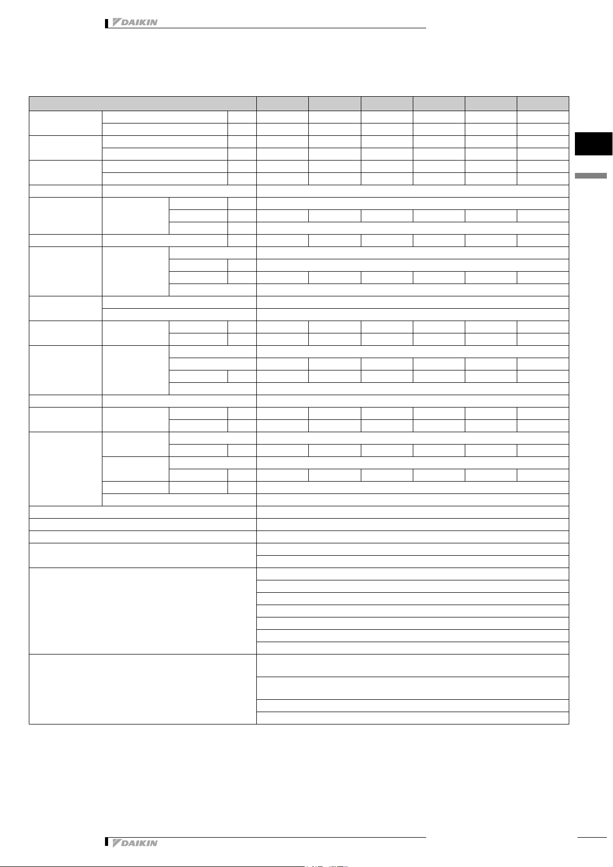
1-1 TECHNICAL SPECIFICATIONS FXLQ20MAVE FXLQ25MAVE FXLQ32MAVE FXLQ40MAVE FXLQ50MAVE FXLQ63MAVE
Capacity Cooling kW 2.20 2.80 3.60 4.50 5.60 7.10
Heating kW 2.50 3.20 4.00 5.00 6.30 8.00
Power Input (50Hz) Cooling kW 0.049 0.049 0.090 0.090 0.110 0.110
Heating kW 0.049 0.049 0.090 0.090 0.110 0.110
Power Input (60Hz) Cooling kW 0.047 0.047 0.079 0.084 0.105 0.108
Heating kW 0.047 0.047 0.079 0.084 0.105 0.108
Casing Colour Ivory white (5Y7,5/1)
Dimensions Unit Height mm 600
Width mm 1000 1000 1140 1140 1420 1420
Depth mm 222
Weight Unit kg 25 25 30 30 36 36
Heat Exchanger Dimensions Nr of Rows 3
Fin Pitch mm 1.50
Face Area m² 0.159 0.159 0.200 0.200 0.282 0.282
Nr of Stages 14
Fan Type Sirocco fan
Quantity 1
Air Flow Rate Cooling High m³/min 7.00 7.00 8.00 11.00 14.00 16.00
Low m³/min 6.00 6.00 6.00 8.50 11.00 12.00
Fan Motor Quantity 1
Model D14B20 D14B20 2D14B13 2D14B13 2D14B20 2D14B20
Output (high)W151525253535
Drive Direct drive
Refrigerant Name R-410A
Cooling Sound Pressure High dBA 35.0 35.0 35.0 38.0 39.0 40.0
Low dBA 32.0 32.0 32.0 33.0 34.0 35.0
Piping connections Liquid (OD) Type Flare connection
Diameter mm 6.35 6.35 6.35 6.35 6.35 9.52
Gas Type Flare connection
Diameter mm 12.7 12.7 12.7 12.7 12.7 15.9
Drain Diameter mm 21
Heat Insulation Glass Fiber/Urethane Foam
Air Filter Resin net with mold resistance
Refrigerant control Electronic expansion valve
Temperature control Microprocessor thermostat for cooling and heating
Safety devices PC board fuse
Fan motor thermal protector
Standard Accessories Installation and operation manual
Insulation for fitting
Drain hose
Clamps
Screws
Level adjustment screw
Washer
Notes Nominal cooling capacities are based on : indoor temperature : 27°CDB, 19°CWB, outdoor temperature
: 35°CDB, equivalent refrigerant piping : 7.5m (horizontal)
Nominal heating capacities are based on : indoor temperature : 20°CDB, outdoor temperature : 7°CDB,
6°CWB, equivalent refrigerant piping : 7.5m (horizontal)
Capacities are net, including a deduction for cooling (an addition for heating) for indoor fan motor heat.
Sound pressure levels are measured at 220V
3
1
1
•VRV® Systems • Indoor Units
3

1 Specifications
1-2 ELECTRICAL SPECIFICATIONS (50HZ) FXLQ20MAVE FXLQ25MAVE FXLQ32MAVE FXLQ40MAVE FXLQ50MAVE FXLQ63MAVE
Power Supply Name VE
Phase 1~
Frequency Hz 50
1
1
Current Minimum circuit amps (MCA) A 0.3 0.3 0.6 0.6 0.6 0.6
Voltage range Minimum V -10%
Notes Voltage range : units are suitable for use on electrical systems where voltage supplied to unit terminals
Voltage V 220-240
Maximum fuse amps (MFA) A 15
Full load amps (FLA) A 0.2 0.2 0.5 0.5 0.5 0.5
Maximum V +10%
• Indoor Units • FLOOR STANDING UNIT • FXLQ-MAVE
is not below or above listed range limits.
Maximum allowable voltage range variation between phases is 2%.
MCA/MFA : MCA = 1.25 x FLA
MFA is smaller than or equal to 4 x FLA
Next lower standard fuse rating minimum 15A
Select wire size based on the MCA
Instead of a fuse, use a circuit breaker
1-3 ELECTRICAL SPECIFICATIONS (60HZ) FXLQ20MAVE FXLQ25MAVE FXLQ32MAVE FXLQ40MAVE FXLQ50MAVE FXLQ63MAVE
Power Supply Name VE
Phase 1~
Frequency Hz 60
Voltage V 220
Current Minimum circuit amps (MCA) A 0.3 0.3 0.5 0.5 0.6 0.6
Maximum fuse amps (MFA) A 15
Full load amps (FLA) A 0.2 0.2 0.4 0.4 0.5 0.5
Voltage range Minimum V -10%
Maximum V +10%
Notes Voltage range : units are suitable for use on electrical systems where voltage supplied to unit terminals
Maximum allowable voltage range variation between phases is 2%.
is not below or above listed range limits.
MCA/MFA : MCA = 1.25 x FLA
MFA is smaller than or equal to 4 x FLA
Next lower standard fuse rating minimum 15A
Select wire size based on the MCA
Instead of a fuse, use a circuit breaker
4
•VRV® Systems • Indoor Units

• Indoor Units • FLOOR STANDING UNIT • FXLQ-MAVE
2 Safety device settings
FXLQ20MA FXLQ25MA FXLQ32MA FXLQ40MA FXLQ50MA FXLQ63MA
PC BOARD FUSE 250V 10A
FAN MOTOR THERMAL PROTECTOR COFF: 135
10
/ ON: 120 or less
3 Options
FXLQ20MA FXLQ25MA FXLQ32MA FXLQ40MA FXLQ50MA FXLQ63MA
LONG LIFE REPLACEMENT FILTER KAFJ361K28 KAFJ361K45 KAFJ361K71
3D034529C
4D034574B
3
1
2
Long life replacement filter
•VRV® Systems • Indoor Units
5
 Loading...