


English
Deutsch
Français
Español
Italiano
Nederlands
Português
Русский
Ελληνικά
INSTALLATION MANUAL
SYSTEM Air Conditioners
MODELS
Ceiling-mounted cassette type (Double flow model)
FXCQ20MVE FXCQ50MVE
FXCQ25MVE FXCQ63MVE
FXCQ32MVE FXCQ80MVE
FXCQ40MVE FXCQ125MVE
CAREFULLY READ THESE INSTRUCTIONS BEFORE INSTALLATION.
KEEP THIS MANUAL IN A HANDY PLACE FOR FUTURE REFERENCE.
LESEN SIE DIESE HINWEISE VOR DER INSTALLATION SORGFÄLTIG DURCH.
BEWAHREN SIE DIESE ANLEITUNG AN EINEM LEICHT ZUGÄNGLICHEN ORT FÜR
SPÄTERES NACHSCHLAGEN AUF.
VEUILLEZ LIRE ATTENTIVEMENT CES INSTRUCTIONS AVANT L'INSTALLATION.
CONSERVEZ CE MANUEL EN LIEU SÛR POUR POUVOIR VOUS Y REPORTER ULTÉRIEUREMENT.
LEA DETENIDAMENTE ESTAS INSTRUCCIONES ANTES DE LA INSTALACIÓN.
CONSERVE ESTE MANUAL PARA POSIBLES CONSULTAS FUTURAS.
PRIMA DELL'INSTALLAZIONE, LEGGERE ATTENTAMENTE LE PRESENTI ISTRUZIONI.
CONSERVARE IL PRESENTE MANUALE IN UN LUOGO FACILMENTE ACCESSIBILE PER
RIFERIMENTO FUTURO.
ΔΙΑΒΑΣΤΕ ΠΡΟΣΕΚΤΙΚΑ ΑΥΤΕΣ ΤΙΣ ΟΔΗΓΙΕΣ ΠΡΙΝ ΤΗΝ ΕΓΚΑΤΑΣΤΑΣΗ.
ΦΥΛΑΞΤΕ ΑΥΤΟ ΤΟ ΕΓΧΕΙΡΙΔΙΟ ΣΕ ΒΟΛΙΚΟ ΜΕΡΟΣ ΓΙΑ ΜΕΛΛΟΝΤΙΚΗ ΑΝΑΦΟΡΑ.
LEES DEZE INSTRUCTIES ZOGVULDIG DOOR VOORDAT MET DE INSTALLATIE WORDT
BEGONNEN.
BEWAAR DEZE HANDLEIDING VOOR TOEKOMSTIG GEBRUIK OP EEN GESCHIKTE
PLAATS ONDER HANDBEREIK.
LEIA ATENTAMENTE ESTAS INSTRUÇÕES ANTES DA INSTALAÇÃO.
MANTENHA ESTE MANUAL NUM LOCAL DE FÁCIL ACESSO PARA CONSULTA.
ПЕРЕД УСТАНОВКОЙ ВНИМАТЕЛЬНО ПРОЧИТАЙТЕ ДАННЫЕ ИНСТРУКЦИИ.
ХРАНИТЕ ДАННОЕ РУКОВОДСТВО В ЛЕГКО ДОСТУПНОМ МЕСТЕ ДЛЯ ЕГО
ПОСЛЕДУЮЩЕГО ИСПОЛЬЗОВАНИЯ.

FXHQ32MAVE, FXHQ63MAVE, FXHQ100MAVE
FXKQ25MAVE, FXKQ32MAVE, FXKQ40MAVE, FXKQ63MAVE
FXAQ20MAVE, FXAQ25MAVE, FXAQ32MAVE, FXAQ40MAVE
FXAQ50MAVE, FXAQ63MAVE
FXUQ71MAV1, FXUQ100MAV1, FXUQ125MAV1
BEVQ71MAVE, BEVQ100MAVE, BEVQ125MAVE
FXLQ20MHV1, FXLQ25MHV1, FXLQ32MHV1, FXLQ40MHV1, FXLQ50MHV1,
FXMQ40MAVE, FXMQ50MAVE, FXMQ63MAVE, FXMQ80MAVE
FXMQ100MAVE, FXMQ125MAVE, FXMQ200MAVE, FXMQ250MAVE
FXLQ20MAVE, FXLQ25MAVE, FXLQ32MAVE, FXLQ40MAVE
FXLQ50MAVE, FXLQ63MAVE
FXNQ20MAVE, FXNQ25MAVE, FXNQ32MAVE, FXNQ40MAVE
FXNQ50MAVE, FXNQ63MAVE
DAIKIN.TCF.022E1/10-2007
TÜV Rheinlard EPS B.V.
0305020101
Umeda Center Bldg., 2-4-12, Nakazaki-Nishi,
Kita-ku, Osaka, 530-8323 Japan
Low Voltage 2006/95/EC
Machinery Safety 98/37/EC
Electromagnetic Compatibility 2004/108/EC
FXKQ25MVE, FXKQ32MVE, FXKQ40MVE, FXKQ63MVE
FXAQ20MVE, FXAQ25MVE, FXAQ32MVE, FXAQ40MVE, FXAQ50MVE, FXAQ63MVE
FXUQ71MV1, FXUQ100MV1, FXUQ125MV1
BEVQ71MVE, BEVQ100MVE, BEVQ125MVE
FXMQ125MFV1, FXMQ200MFV1, FXMQ250MFV1
FXAQ20MHV1, FXAQ25MHV1, FXAQ32MHV1, FXAQ40MHV1, FXAQ50MHV1
BEVQ50MVE
Shinri Sada
Manager Quality Control Department
1st of May 2009
FXZQ20MVE, FXZQ25MVE, FXZQ32MVE, FXZQ40MVE, FXZQ50MVE
FXCQ20MVE, FXCQ25MVE, FXCQ32MVE, FXCQ40MVE, FXCQ50MVE, FXCQ63MVE, FXCQ80MVE, FXCQ125MVE
FXMQ40MVE, FXMQ50MVE, FXMQ63MVE, FXMQ80MVE, FXMQ100MVE, FXMQ125MVE, FXMQ200MVE, FXMQ250MVE
FXLQ20MVE, FXLQ25MVE, FXLQ32MVE, FXLQ40MVE, FXLQ50MVE, FXLQ63MVE
FXNQ20MVE, FXNQ25MVE, FXNQ32MVE, FXNQ40MVE, FXNQ50MVE, FXNQ63MVE
FXHQ32MVE, FXHQ63MVE, FXHQ100MVE
DAIKIN INDUSTRIES, LTD.
FXSQ20MVE, FXSQ25MVE, FXSQ32MVE, FXSQ40MVE, FXSQ50MVE, FXSQ63MVE, FXSQ80MVE, FXSQ100MVE, FXSQ125MVE
EN60335-2-40,
3P109591-1E

VRV SYSTEM Air Conditioners Installation manual
WARNING
CAUTION
CONTENTS
1. SAFETY PRECAUTIONS................................................ 1
2. BEFORE INSTALLATION ................................................ 2
3. SELECTING INSTALLATION SITE ................................. 3
4. PREPARATIONS BEFORE INSTALLATION.................... 4
5. INDOOR UNIT INSTALLATION ....................................... 4
6. REFRIGERANT PIPING WORK ..................................... 5
7. DRAIN PIPING WORK .................................................... 7
8. ELECTRIC WIRING WORK ............................................ 8
9. WIRING EXAMPLE AND HOW TO SET
THE REMOTE CONTROLLER........................................ 9
10. DECORATION PANEL INSTALLATION ......................... 11
11. FIELD SETTINGS ......................................................... 11
12. TEST OPERATION........................................................ 11
The original instructions are written in English. All other languages are translations of the original instructions.
1. SAFETY PRECAUTIONS
Be sure to follow this “SAFETY PRECAUTIONS”.
This product comes under the term “appliances not accessible
to the general public”.
This is a class A product. In a domestic environment this product may cause radio interference in which case the user may be
required to take adequate measures.
This manual classifies the precautions into WARNINGS and
CAUTIONS.
Be sure to follow all the precautions below: They are all important for ensuring safety.
WARNING ............. Indicates a potentially hazardous situ-
ation which, if not avoided, could result
in death or serious injury.
CAUTION .............. Indicates a potentially hazardous situ-
ation which, if not avoided, may result
in minor or moderate injury.
It may also be used to alert against
unsafe practices.
• After the installation is completed, test the air conditioner and
check if the air conditioner operates properly. Give the user
adequate instructions concerning the use and cleaning of the
indoor unit according to the Operation Manual. Ask the user
to keep this manual and the Operation Manual together in a
handy place for future reference.
• Ask your local dealer or qualified personnel to carry out installation work.
Improper installation may result in water leakage, electric
shocks or a fire.
• Perform installation work in accordance with this installation
manual.
Improper installation may result in water leakage, electric
shocks or a fire.
• Consult your local dealer regarding what to do in case of
refrigerant leakage.
When the air conditioner is installed in a small room, it is necessary to take proper measures so that the amount of any
leaked refrigerant does not exceed the concentration limit in
the event of a leakage.
Otherwise, this may lead to an accident due to oxygen deficiency.
• Be sure to use only the specified parts and accessories for
installation work.
Failure to use the specified parts may result in the air conditioner falling down, water leakage, electric shocks, a fire, etc.
• Install the air conditioner on a foundation that can withstand
its mass.
Insufficient strength may result in the air conditioner falling
down and causing injury.
In addition, it may lead to vibration of indoor units and cause
unpleasant chattering noise.
• Carry out the specified installation work in consideration of
strong winds, typhoons, or earthquakes. Improper installation may result in an accident such as air conditioner falling.
• Make certain that all electrical work is carried out by qualified
personnel according to the applicable legislation (note 1) and
this installation manual, using a separate circuit.
In addition, even if the wiring is short, make sure to use a wiring that has sufficient length and never connect additional
wiring to make the length sufficient.
Insufficient capacity of the power supply circuit or improper
electrical construction may lead to electric shocks or a fire.
(note 1) applicable legislation means “All international,
national and local directives, laws, regulations and/
or codes which are relevant and applicable for a
certain product or domain”.
• Make sure that all wiring is secure, using the specified wiring
and ensuring that external forces do not act on the terminal
connections or wiring.
Incomplete connection or fixing may cause an overheat or a
fire.
• When wiring the remote controller wiring and transmission
wiring, and wiring the power supply, form the wiring orderly
so that the control box cover can be securely fastened.
If the control box cover is not in place, overheat of the terminals, electric shocks or a fire may be caused.
If refrigerant gas leaks during installation work, ventilate the
•
area immediately.
Toxic gas may be produced if refrigerant gas comes into contact with a fire.
•
After completing the installation work, check to make sure that
there is no leakage of refrigerant gas.
Toxic gas may be produced if refrigerant gas leaks into the
room and comes into contact with a source of a fire, such as a
fan heater, stove or cooker.
• Disconnect the power supply before touching the electric
components.
If you touch the live part, you may get an electric shocks.
• Earth the air conditioner.
Do not connect the earth wiring to gas or water piping, lightning conductor or telephone earth wiring.
Incomplete earthing may cause electric shocks or a fire.
A high surge current from lightning or other sources may
cause damage to the air conditioner.
• Be sure to install an earth leakage circuit breaker.
Failure to do so may cause electric shocks and a fire.
• Install drain piping according to this installation manual to
ensure good drainage, and insulate the piping to prevent
condensation.
English 1
Improper drain piping may cause water leakage, make the
furniture get wet.
• Install the air conditioner, power supply wiring, remote controller wiring and transmission wiring at least 1 meter away
from televisions or radios to prevent image interference or
noise.
(Depending on the radio waves, a distance of 1 meter may
not be sufficient to eliminate the noise.)
• Install the indoor unit as far as possible from fluorescent
lamps.
If a wireless remote controller kit is installed, the transmission
distance may be shorter in a room where an electronic lighting type (inverter or rapid start type) fluorescent lamp is
installed.
• Do not install the air conditioner in places such as the following:
1. Where there is mist of oil, oil spray or vapour for example
a kitchen.
Resin parts may deteriorate, and cause them to fall out or
water to leak.
2. Where corrosive gas, such as sulfurous acid gas, is pro-
duced.
Corrosion of copper pipings or brazed parts may cause
the refrigerant to leak.
3. Where there is machinery which emits electromagnetic
waves.
Electromagnetic waves may disturb the control system,
and cause malfunction of the equipment.
4. Where flammable gases may leak, where carbon fibre or
ignitable dust is suspended in the air or where volatile
flammables, such as thinner or gasoline, are handled.
If the gas should leak and remained around the air conditioner, it may cause ignition.
• The air conditioner is not intended for use in a potentially
explosive atmosphere.
• Where exposed to combustible gases and where vol-
atile flammable gas like thinner or gasoline is used.
(Gas in the vicinity of the unit could ignite.)
• Where machines can generate electromagnetic
waves. (Control system may malfunction.)
• Where the air contains high levels of salt such as that
near the ocean and where voltage fluctuates greatly
such as that in factories. Also in vehicles or vessels.
This unit, both indoor and outdoor, is suitable for installation in
•
a commercial and light industrial environment.
If installed as a household appliance it could cause electromagnetic interference.
2-1 PRECAUTIONS
• Be sure to read this manual before installing the indoor unit.
• Entrust installation to the place of purchase or a qualified serviceman. Improper installation could lead to leaks and, in
worse cases, electric shock of fire.
• Use only parts provided with the unit or parts satisfying
required specifications. Unspecified parts could cause the
unit to fall out of place, or could lead to leaks and, in worse
cases, electric shock or fire.
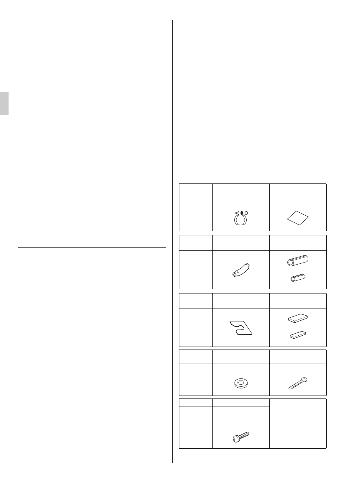
2-2 ACCESSORIES
Check the following accessories are included with your unit.
Name Metal clamp
Quantity 1 pc. 1 pc.
Shape
Name Drain hose
Quantity 1 pc. 1 each
Paper pattern for
installation
Insulation for fitting
2. BEFORE INSTALLATION
• When moving the unit while removing it from the carton
box, be sure to lift it by holding on to the four lifting lugs
without exerting any pressure on other parts, especially,
the refrigerant piping, drain piping, and other resin
parts.
• Be sure to check the type of R410A refrigerant to be used
before installing the unit. (Using an incorrect refrigerant will
prevent normal operation of the unit.)
• The accessories needed for installation must be retained in
your custody until the installation work is completed. Do not
discard them!
• Decide upon a line of transport.
• Leave the unit inside its packaging while moving, until reaching the installation site. Where unpacking is unavoidable, use
a sling of soft material or protective plates together with a
rope when lifting, to avoid damage or scratches to the unit.
• When moving the unit at or after opening, hold the unit by the
hanger brackets (×4). Do not apply force to the refrigerant
piping, drain piping or plastic parts.
• When selecting installation site, refer to the paper pattern.
• For the installation of an outdoor unit, refer to the installation
manual attached to the outdoor unit.
• Do not install or operate the unit in rooms mentioned below.
• Laden with mineral oil, or filled with oil vapor or spray
like in kitchens. (Plastic parts may deteriorate which
could eventually cause the unit to fall out of place, or
could lead to leaks.)
• Where corrosive gas like sulfurous gas exists. (Cop-
per tubing and brazed spots may corrode, which
could eventually lead to refrigerant leaks.)
Shape
Name Washer fixing plate Sealing pad
Quantity 4 pcs. 1 each
Shape
Name
Quantity 8 pcs. 8 pcs.
Shape
Name Screws (M5)
Quantity 4 pcs.
Shape
Washer for hanging
bracket
For paper pattern for
installation
for gas pipe
for liquid pipe
Large
Small
Clamp
(Other)
• Operation manual
• Installation manual
• Screws for fixing panels are attached to decoration panel.
2 English

2-3 OPTIONAL ACCESSORIES
NOTE
The items with WARNING and CAUTION marks
in the instruction manual are the items pertaining to
possibilities for bodily injury and material damage in
addition to the general usage of the product. Accordingly, it
is necessary that you make a full explanation about the
described contents and also ask your customers to read the
instruction manual.
• The optional decoration panel and remote controller are
required for this indoor unit. (Refer to Table 1)
• These are two types of remote controllers: wired and wireless. Select a remote controller from Table 2 according to
customer request and install in an appropriate place.
Tabl e 1
Model
FXCQ20 · 25 · 32MVE BYBC32GJW1 · BYBC32G-W1
FXCQ40 · 50MVE BYBC50GJW1 · BYBC50G-W1
FXCQ63MVE BYBC63GJW1 · BYBC63G-W1
FXCQ80 · 125MVE BYBC125GJW1 · BYBC125G-W1
Optional decoration panel
White
Tabl e 2
Remote controller
Wired type
Wireless type
Heat pump type
Cooling only type
• If the you wishes to use a remote controller that is not listed
above, select a suitable remote controller after consulting
catalogs and technical materials.
FOR THE FOLLOWING ITEMS, TAKE SPECIAL
CARE DURING CONSTRUCTION AND CHECK
AFTER INSTALLATION IS FINISHED.
a. Items to be checked after completion of work
Items to be checked
Are the indoor and outdoor
unit fixed firmly?
Is the gas leak test finished?
Is the unit fully insulated? Condensate water may drip.
Does drainage flow
smoothly?
Does the power supply volt-
age correspond to that
shown on the name plate?
Are wiring and piping correct?
Is the unit safely grounded?
Is wiring size according to
specifications?
Is something blocking the air
outlet or inlet of either the
indoor or outdoor units?
Are refrigerant piping length
and additional refrigerant
charge noted down?
If not properly done, what is
likely to occur
The units may drop, vibrate
or make noise.
It may result in insufficient
cooling.
Condensate water may drip.
The unit may malfunction or
the components burn out.
The unit may malfunction or
the components burn out.
Dangerous at electric leakage.
The unit may malfunction or
the components burn out.
It may result in insufficient
cooling.
The refrigerant charge in the
system is not clear.
Check
c. Points for explanation about operations
2-4 NOTES TO INSTALLER
Be sure to instruct customers how to properly operate the
unit (especially cleaning filters, operating different functions,
and adjusting the temperature) by having them carry out
operations themselves while looking at the manual.
3. SELECTING INSTALLATION SITE
Please attach additional thermal insulation material to the unit
body when it is believed that the relative humidity in the ceiling
exceeds 80%. Use glass wool, polyethylene foam, or similar
with a thickness of 10 mm or more as thermal insulation material.
(1) Select an installation site where the following condi-
tions are fulfilled and that meets with your
customer’s approval.
• Where optimum air distribution can be ensured.
• Where nothing blocks air passage.
• Where condensate can be properly drained.
• In the upper space of the indoor unit where there is no
possible dripping of water from the refrigerant pipe, drain
pipe, water pipe, etc.
• If supporting structural members are not strong enough
to take the unit’s weight, the unit could fall out of place
and cause serious injury.
• Where the false ceiling is not noticeably on an incline.
• Where there is no risk of flammable gas leakage.
• Where sufficient clearance for maintenance and service
can be ensured.
• Where piping between indoor and outdoor units is possible within the allowable limit. (Refer to the installation
manual for the outdoor unit.)
• Any vents, light fixtures, or other appliances which may
disturb the airflow might cause the top side to become
dirty if located too nearby, so follow the figure below when
installing.
• Install the indoor and outdoor units, power supply wiring
and connecting wires at least 1 meter away from televisions or radios in order to prevent image interference or
noise.
(Depending on the radio waves, a distance of 1 meter
may not be sufficient enough to eliminate the noise.)
b. Items to be checked at time of delivery
Also review the “SAFETY PRECAUTIONS”
Items to be checked Check
Did you explain about operations while showing the
instruction manual to your customer?
Did you hand the instruction manual over to your cus-
tomer?
English 3
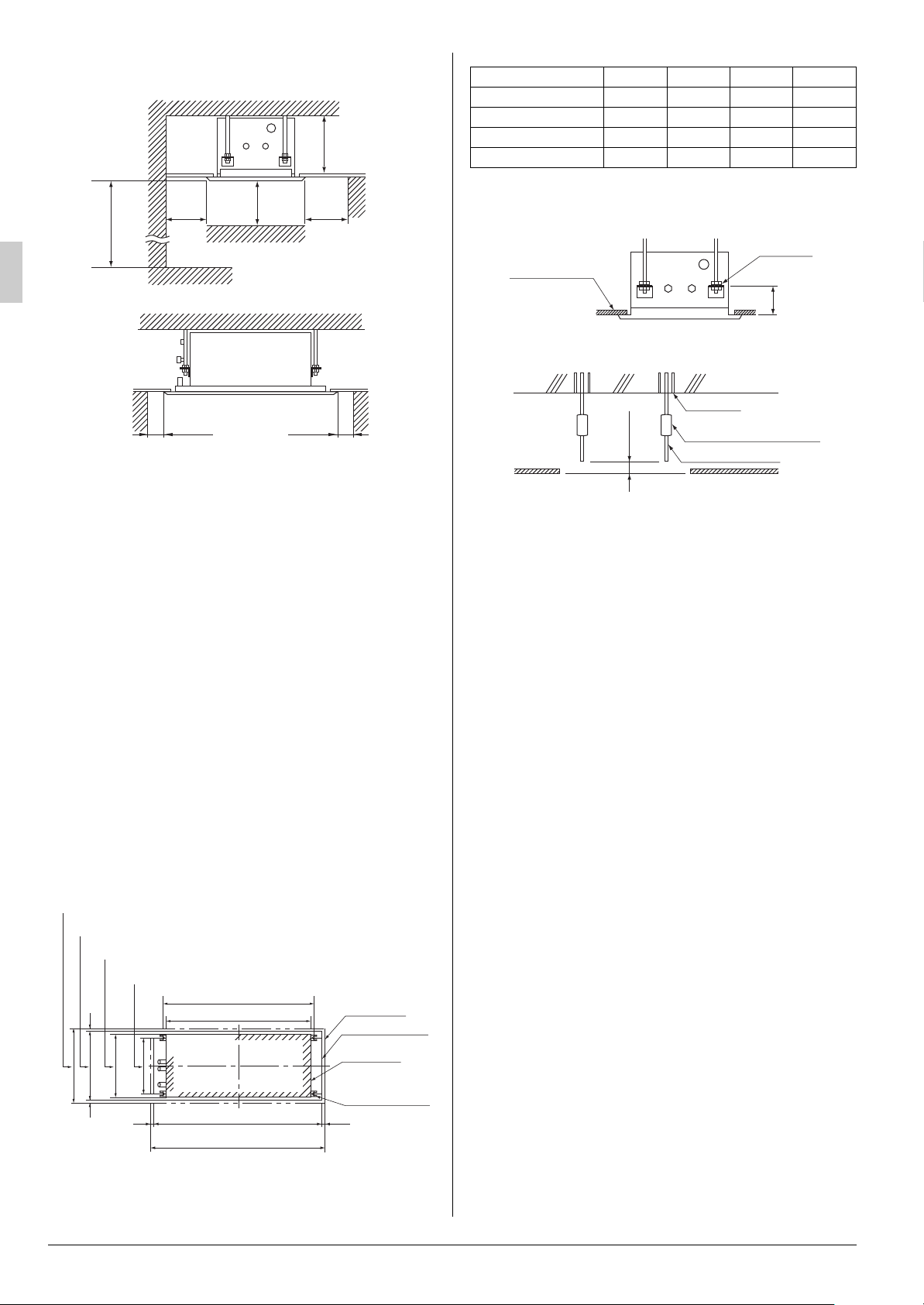
2500 or more
Decoration
panel
Ceiling opening
Indoor unit
Suspension bolt
(× 4)
D (Panel outside dimensions)
A (Ceiling opening)
B (Suspension pitch)
C (Unit outside dimensions)
20
20
20
20
680 (Panel outside dimensions)
640 (Ceiling opening)
600 (Unit outside dimensions)
520 (Suspension pitch)
(length:mm)
160
[ Relative positioning of ceiling and unit ]
Hanger
Ceiling surface
(length:mm)
For installation
in high places
[ Space required for installation ]
350
1000
100 100
15001500
(length:mm)
Model A (mm) B (mm) C (mm) D (mm)
FXCQ20 · 25 · 32MVE 990 820 775 1030
FXCQ40 · 50MVE 1205 1035 990 1245
FXCQ63MVE 1390 1220 1175 1430
FXCQ80 · 125MVE 1880 1710 1665 1920
(2) Make the ceiling opening needed for installation, where
applicable.
[ Installation example ]
Ceiling slab
Anchor
Long nut or turn-buckle
100mm
Suspension bolt
[ PRECAUTION ]
If installing the wireless kit in a room with electronic fluorescent lighting (inverter or rapid start type), the remote controller’s transmission distance may be shortened. Indoor
units should be installed as far away from fluorescent lighting as possible.
(2) Ceiling height
These units can be installed with ceilings up to 3 m in
height.
Install this unit where the height of bottom panel is more
than 2.5 m so that the user cannot easily touch.
(3) Use suspension bolts for installation. Check whether
the ceiling is strong enough to support the weight of
the unit or not. If there is a risk, reinforce the ceiling
before installing the unit.
(Installation pitch is marked on the paper pattern for installation. Refer to it to check for points requiring reinforcing.)
4. PREPARATIONS BEFORE INSTALLATION
(1) Relation of ceiling opening to units and suspension
bolt position
False ceiling
Note: All the above parts are field supplied.
• Refer to the paper pattern for installation for ceiling opening dimension.
• Create the ceiling opening required for installation. From
the side of the opening to the casing outlet, implement
the refrigerant and drain piping and wiring for remote controller (unnecessary for wireless type) and indoor-outdoor unit casing outlet. Refer to each PIPING or WIRING
section.
• After making an opening in the ceiling, it may be necessary to reinforce ceiling beams to keep the ceiling level
and to prevent it from vibrating. Consult the builder for
details.
(3) Install the suspension bolts. (Use either a W3/8 or M10
size bolt.)
Use a hole-in-anchor for existing ceilings, and a sunken
insert, sunken anchor or other part to be procured in the
field for new ceilings to reinforce the ceiling to bearing the
weight of the unit. Adjust clearance from the ceiling before
proceeding further.
5. INDOOR UNIT INSTALLATION
Installing optional accessories (except for the decoration
panel) before installing the indoor unit is easier. However,
for existing ceilings, install branch duct before installing
the unit.
As for the parts to be used for installation work, be sure to use
the provided accessories and specified parts designated by our
company.
4 English
(1) Install the indoor unit temporarily.
• Attach the hanger bracket to the suspension bolt. Be sure
to fix it securely by using a nut and washer from the upper
and lower sides of the hanger bracket. The washer fixing
plate will prevent the washer from falling.

CAUTION
CAUTION
Part to be procured in the field
Cut-out section
Paper pattern
for installation
Screws (× 4 accessory)
(accessory)
[ Installation of paper pattern for installation ]
Guide section (4 corners)
Paper pattern
for installation
Ceiling
Lower
surface
of the
ceiling
[ Unit height adjustment ]
(accessory)
The unit body
Ceiling
Lower
surface of
the ceiling
The guide portion
[ Unit height adjustment ]
Washer (accessory)
Hanger bracket
(4) Check the unit is horizontally level.
Tighten
(double nut)
[ Securing the hanger bracket ]
Insert
Washer fixing plate
(accessory)
[ Securing the washer ]
[ For new ceilings ]
(2) Refer to the paper pattern for installation for ceiling
opening dimension. Consult the builder or carpenter
for details.
• The center of the ceiling opening is indicated on the
paper pattern for installation.
• After cutting out a slit for the unit in the center of the paper
pattern for installation (accessory), install with the 4
screws (accessory).
• Fold the guide section of paper pattern for installation and
adjust the height of the unit so the notch in the guide is at
the position where you expect the ceiling surface to be.
Level
Vinyl tube
The indoor unit is equipped with a built-in drain pump
and float switch. At each of the unit’s 4 corners, verify
that it is level by using a level or a water-filled vinyl
tube. (If the unit is inclined against condensate flow,
the float switch may malfunction and cause water to
drip.)
(5) Remove the washer fixing plate used for preventing the
washer from falling and tighten the upper nut.
(6) Remove the paper pattern for installation.
[ For existing ceilings ]
(2) Adjust the height of the unit.
Cut out the guide section of the paper pattern for installation
attached, place on the bottom surface of the unit, and adjust
the height of the unit so that the notch of the guide matches
the lower surface of the ceiling.
Ceiling work
(3) Adjust the unit to the right position for installation.
English 5
(Refer to “
PREPARATIONS BEFORE INSTALLATION-(1)
”.)
(3) Perform steps (3), (4), (5) in For new ceilings.
6. REFRIGERANT PIPING WORK
• For the outdoor unit refrigerant piping, refer to the installation
manual attached to the outdoor unit.
• Carry out insulation of both gas and liquid refrigerant piping
securely. If not insulated, it may cause water leakage. For
gas piping, use insulation material of which heat resistant
temperature is not less than 120°C.
For use under high humidity, strengthen the insulation material for refrigerant piping. If not strengthened, the surface of
insulation material may sweat.
• Before installation work, make sure that the refrigerant is
R410A. (Unless the refrigerant is R410A, the normal operation cannot be expected.)
This air conditioner is a dedicated model for new refrigerant R410A. Make sure to meet the requirements shown
below and carry out installation work.
• Use dedicated piping cutters and flaring tools for
R410A.
• When making a flare connection, coat the flared inner
surface only with ether oil or ester oil.
• Use only the flare nuts attached to the air conditioner.
If other flare nuts are used, it may cause refrigerant
leakage.
• To prevent contamination or moisture from getting
NOTE
CAUTION
CAUTION
CAUTION
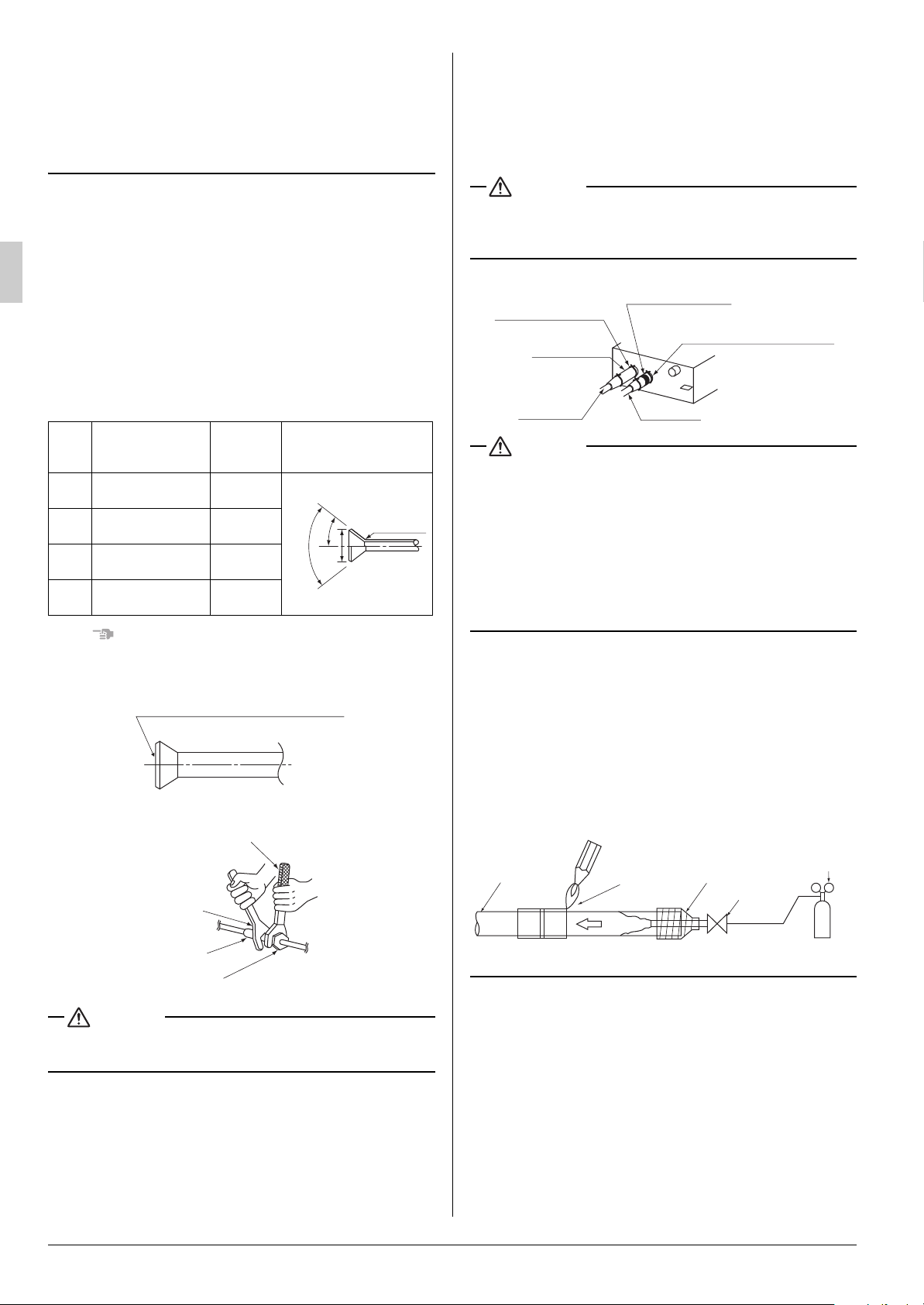
Coat the flared inner surface only with
ether oil or ester oil.
Fig. 1
Torque wrench
Spanner
Piping union
Flare nut
Fig. 2
Insulation for fitting
(accessory)
Small sealing pad
Insulation for fitting
(accessory)
(for gas line)
Clamp (×4)
(accessory)
(for liquid line)
Liquid pipe
Fig. 3
(accessory)
Gas pipe
into the piping, take measures such as pinching or
taping the pipings.
Do not mix substance other than the specified refrigerant such as air into the refrigeration circuit.
If the refrigerant leaks during the work, ventilate the
room.
• The refrigerant is pre-charged in the outdoor unit.
• When connecting the pipings to the air conditioner, make
sure to use a spanner and a torque wrench as shown in
Fig. 1.
• For the dimension of flared part and the tightening torque,
refer to the Table 3.
• When making a flare connection, coat the flared inner surface only with ether oil or ester oil.
(Refer to Fig. 2)
Then, turn the flare nut 3 to 4 times with your hand and screw
in the nut.
• Refer to Table 3 for tightening torque.
Tabl e 3
Pipe
gauge
6.4
(1/4”)
9.5
(3/8”)
12.7
(1/2”)
15.9
(5/8”)
Tightening torque
(N·m)
15.7 ± 1.5 8.9 ± 0.2
36.3 ± 3.6 13.0 ± 0.2
54.9 ± 5.4 16.4 ± 0.2
68.6 ± 6.8 19.5 ± 0.2
Flare
dimension A
(mm)
Flare shape
0
±
0
0
2
±
45
0
90
2
R0.4-0.8
A
• Make absolutely sure to execute heat insulation works on the
pipe-connecting section after checking gas leakage by thoroughly studying the following figure and using the attached
heat insulating materials for fitting. (Fasten both ends with
the clamps (accessory).) (Refer to Fig. 3)
• Wrap the sealing pad (accessory) only around the insulation
for the joints on the gas piping side.
Be sure to insulate any field piping all the way to the piping
connection inside the unit. Any exposed piping may cause
condensation or burns if touched.
CAUTION TO BE TAKEN WHEN BRAZING REFRIGERANT PIPING
Do not use flux when brazing refrigerant piping. Therefore,
use the phosphor copper brazing filler metal (BCuP-2: JIS Z
3264/B-Cu93P-710/795: ISO 3677) which does not require
flux.
(Flux has extremely harmful influence on refrigerant piping
systems. For instance, if the chlorine based flux is used, it will
cause pipe corrosion or, in particular, if the flux contains fluorine, it will damage the refrigerant oil.)
The flare nuts used must be those included with the main body.
Over-tightening may damage the flare and cause a refrigerant leakage.
Use “ Table 4 ” as a reference if a torque wrench is not available.
Once work is complete, make sure there is no gas leaking. As
the flare nut is tightened with the wrench, the torque will suddenly increase.
From that position, tighten the nut to the angle shown on “ Table 4 ”.
6 English
• Before brazing local refrigerant piping, nitrogen gas shall be
blown through the piping to expel air from the piping.
If your brazing is done without nitrogen gas blowing, a large
amount of oxide film develops inside the piping, and could
cause system malfunction.
• When brazing the refrigerant piping, only begin brazing after
having carried out nitrogen substitution or while inserting
nitrogen into the refrigerant piping. Once this is done, connect the indoor unit with a flared or a flanged connection.
• Nitrogen should be set to 0.02 MPa with a pressure-reducing
valve if brazing while inserting nitrogen into the piping.
Pressure-
Refrigerant
piping
Part to be
brazed
Nitrogen
Taping
hands valve
reducing
valve
Nitrogen
Not recommendable but in case of emergency
You must use a torque wrench but if you are obliged to install
the unit without a torque wrench, you may follow the installation method mentioned below.
After the work is finished, make sure to check that there
is no gas leak.
When you keep on tightening the flare nut with a spanner,
there is a point where the tightening torque suddenly
increases. From that position, further tighten the flare nut the
angle shown below:

Tabl e 4
CAUTION
1-1.5m
1-1.5m
Hanger bracket
Ceiling slab
600
mm
310mm)
290
mm
1-1.5m
300mm
Hanger bracket
Adjustable
Drain raising pipe
Drain hose (accessory)
Metal clamp (accessory)
Portable pump
Water inlet lid
Close
Open
Bucket
Refrigerant
piping
Water inlet
Pipe size Further tightening angle
6.4 (1/4”) 60 to 90 degrees Approx. 150mm
9.5 (3/8”) 60 to 90 degrees Approx. 200mm
12.7 (1/2”) 30 to 60 degrees Approx. 250mm
15.9 (5/8”) 30 to 60 degrees Approx. 300mm
Recommended arm length
of tool
Metal clamp
(accessory)
Large sealing pad
(accessory)
4mm
7. DRAIN PIPING WORK
Rig the drain pipe as shown below and take measures
against condensation. Improperly rigged piping could lead
to leaks and eventually wet furniture and belongings.
(1) Carry out the drain piping
• The diameter of the drain pipe should be greater than or
equal to the diameter of the connecting pipe (vinyl tube;
pipe size: 25 mm; outer dimension: 32 mm).
• Keep the drain pipe short and sloping downwards at a
gradient of at least 1/100 to prevent air pockets from
forming.
• If the drain hose cannot be sufficiently set on a slope, execute the drain raising piping.
• To keep the drain hose from sagging, space hanging
wires every 1 to 1.5 m.
PRECAUTIONS FOR DRAIN RAISING PIPING
• Install the drain raising pipes at a height of less than
310 mm.
• Install the drain raising pipes at a right angle to the indoor
unit and no more than 300 mm from the unit.
• If converging multiple drain pipes, install according to the
procedure shown below.
100mm
T-joint converging drain pipes
Setting the unit at an angle opposite to the drain piping
might cause leaks.
• Use the drain hose and the metal clamp.
Insert the drain hose into the drain socket, up to the tape.
Tighten the clamp until the screw head is less than 4 mm
from the hose.
• Wrap the attached sealing pad over the clamp and drain
hose to insulate.
• Insulate the drain hose inside the building.
English 7
Tape
Metal clamp
Drain hose
Select converging drain pipes whose gauge is suitable for
the operating capacity of the unit.
(2) After piping work is finished, check drainage flows
smoothly.
• Open the water inlet lid, add approximately 2.5 liter of
water gradually and check drainage flow.
[ WHEN ELECTRIC WIRING WORK IS FINISHED ]
• Check drainage flow during COOL running, explained under
“TEST OPERATION.”
[ WHEN ELECTRIC WIRING WORK IS NOT FINISHED ]
CAUTION
NOTE
Terminal block
220V-240V single
phase power supply
Electric parts
box lid
TEST
• Telephone ground wires or lightning rods : might cause
abnormally high electric potential in the ground during
lighting storms.
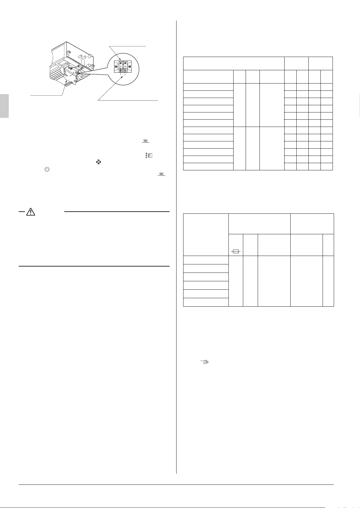
8-2 ELECTRICAL CHARACTERISTICS
• Remove the electric parts box lid, connect a power supply
and remote controller to the terminals.
(Refer to the “HOW TO CONNECT WIRINGS”)
Be sure attach the electric parts box lid before turning on the
power.
Next, press the inspection/test operation button “ ” on the
TEST
remote controller. The unit will engage the test operation
mode. Press the operation mode selector button “ ” until
selecting FAN OPERATION “ ”. Then, press the ON/OFF
button “ ”. The indoor unit fan and drain pump will start up.
Check that the water has drained from the unit. Press “ ”
to go back to the first mode.
• Be careful when doing so because the fan is turning at
the same time.
• Attach the electric parts box lid as before.
• Drain piping connections
Do not connect the drain piping directly to sewage pipes that
smell of ammonia. The ammonia in the sewage might enter
the indoor unit through the drain pipes and corrode the heat
exchanger.
• Keep in mind that it will become the cause of getting drain
pipe blocked if water collects on drain pipe.
8. ELECTRIC WIRING WORK
8-1 GENERAL INSTRUCTIONS
• All field supplied parts and materials and electric works must
conform to local codes.
• Use copper wire only.
• For electric wiring work, refer to also
attached to the electric parts box lid.
• For remote controller wiring details, refer to the installation
manual attached to the remote controller.
• All wiring must be performed by an authorized electrician.
• This system consists of multiple indoor units. Mark each
indoor unit as unit A, unit B..., and be sure the terminal board
wiring to the outdoor unit and BS unit are properly matched.
If wiring and piping between the outdoor unit and an indoor
unit are mismatched, the system may cause a malfunction.
• A circuit breaker capable of shutting down power supply to
the entire system must be installed.
• Refer to the installation manual attached to the outdoor unit
for the size of power supply wiring connected to the outdoor
unit, the capacity of the circuit breaker and switch, and wiring
instructions.
• Be sure to ground the air conditioner.
• Do not connect the ground wire to gas and water pipes, lightning rods, or telephone ground wires.
• Gas pipes
: might cause explosions or fire if gas leaks.
• Water pipes : no grounding effect if hard vinyl piping is
used.
“Wiring diagram label”
Units
220-
240
Voltage
range
Max. 264
Min. 198
Max. 242
Min. 198
Model
FXCQ20MVE
FXCQ25 · 32MVE 0.5 15 0.015 0.4
FXCQ40 · 50MVE 0.8 15 0.020 0.6
FXCQ63MVE 0.9 15 0.030 0.7
FXCQ80MVE 1.1 15 0.050 0.9
FXCQ125MVE 1.3 15 0.085 1.0
FXCQ20MVE
FXCQ25 · 32MVE 0.5 15 0.015 0.4
FXCQ40 · 50MVE 0.8 15 0.020 0.6
FXCQ63MVE 0.9 15 0.030 0.7
FXCQ80MVE 1.3 15 0.050 1.0
FXCQ125MVE 1.5 15 0.085 1.2
Hz Volts
50
60 220
Power
supply
MCA MFA kW FLA
0.5 15 0.010 0.4
0.5 15 0.010 0.4
Fan motor
MCA:Min. Circuit Amps (A); MFA:Max. Fuse Amps (A)
kW: Fan Motor Rated Output (kW); FLA:Full Load Amps (A)
8-3 SPECIFICATIONS FOR FIELD SUPPLIED
FUSES AND WIRE
Remote controller
Power supply wiring
Model
FXCQ20MVE
FXCQ25 · 32MVE
FXCQ40 · 50MVE
FXCQ63MVE
FXCQ80MVE
FXCQ125MVE
Field
fuses
Wire Size Wire Size
Wiring size
H05VV
15A
-U3G
NOTE 1)
and length
must comply
with local
codes.
Allowable length of transmission wiring between indoor/outdoor
units and between the indoor unit and the remote controller is as
follows.
(1) Outdoor unit – Indoor unit:
Max. 1000 m (Total wiring length: 2000 m)
(2) Indoor unit – Remote controller:
Max. 500 m
1. Shows only in case of protected piping. Use H07RN-F in
case of no protection.
2. Vinyl cord with sheath or cable (Insulated thickness : 1mm
or more)
wiring
Transmission wiring
Sheathed wire
(2 wire)
NOTE 2)
0.75
-
1.25
mm
2
8 English

9. WIRING EXAMPLE AND HOW TO SET
CAUTION
CAUTION FOR WIRING
WARNING
Insulation sleeve
Ring type crimp
style terminals
Wiring
Fig. 4
Fig. 5
Use wires the same in size
(if the air conditioner is
in simultaneous multi operation)
P
1
P
2
F
1
F
2
T
1
T
2
Terminal block for unit
transmission wirings
Clamp
(accessory)
Transmission wiring
between units
Remote controller
wiring (*)
Power supply wiring (*)
Ground terminal
Power supply
terminal block
Field supplied wire
Ground wiring (*)
THE REMOTE CONTROLLER
9-1 HOW TO CONNECT WIRINGS
Methods of wiring power supply, connecting transmission
and remote controller wiring
• Do not carry out soldering finish when stranded wires are
used. (Otherwise, the loosening of wires may result in abnormal heat radiation.)
Remote controller wiring
Transmission wiring
Terminal block for
remote controller wiring
Electric
parts box
Electric parts box lid
Guide
plate
Power
supply
wiring
Ground
wiring
Terminal block for
power supply
• Power supply wiring
Remove the electric parts box lid shown in the figure, and
connect to the terminal block (power supply) inside. At this
time, run the wiring from the power supply side of the guide
plate to inside the machine.
• Transmission wiring and remote controller wiring
Connect the terminal block (remote controller / transmission
wiring) so there is no mistake. At this time, run the remote
controller / transmission wiring from the transmission wiring
side of the guide plate to inside the machine.
• Be sure to attach the sealing material or putty (field supplied)
to hole of wiring to prevent the infiltration of water as well as
any insects and other small creatures from outside. Otherwise a short-circuit may occur inside the electric parts box.
• When clamping the wires, be sure no pressure is applied to
the wire connections by using the included clamping material
to make appropriate clamps. Also, when wiring, make sure
the lid on the electric parts box fits snugly by arranging the
wires neatly and attaching the electric parts box lid firmly.
When attaching the electric parts box lid, make sure no wires
get caught in the edges. Pass wiring through the wiring
through holes to prevent damage to them.
• Make sure the remote controller wiring, the wiring between
the units, and other electrical wiring do not pass through the
same locations outside of the unit, separating them by at
least 50mm, otherwise electrical noise (external static) could
cause mistaken operation or breakage.
(Abnormal heating may occur if the wirings are not tightened
securely.)
• Use the required wirings, connect them securely and fix
these wirings securely so that external force may not apply to
the terminals.
• Use a proper screw driver for tightening the terminal screws.
If an improper screw driver is used, it may damage the screw
head and a proper tightening cannot be carried out.
If a terminal is over tightened, it may be damaged.
•
Refer to the table shown below for tightening torque of terminals
Tabl e 5
Tightening torque (N · m)
Terminal block for remote controller
and transmission wiring
Terminal for power supply 1.47 ± 0.14
Earth terminal 1.69 ± 0.25
0.88 ± 0.08
• Do not carry out soldering finish when stranded wirings are
used.
• When wiring, form the wirings orderly so that the control box
lid can be securely fastened. If the control box lid is not in
place, the wirings may come out or be sandwiched by the box
and the lid and cause electric shocks or a fire.
• Use only specified wire and tightly connect wires to terminals. Be careful wires do not place external stress on terminals. Keep wiring in neat order and so as not to obstruct other
equipment such as popping open the electric parts box lid.
Make sure the lid closes tight. Incomplete connections could
result in overheating, and in worse case, electric shock or
fire.
.
• For connection to the terminal block, use ring type crimp style
terminals with insulation sleeve or insulate the wirings properly.
• Connect the terminal as shown in Fig. 5.
English 9
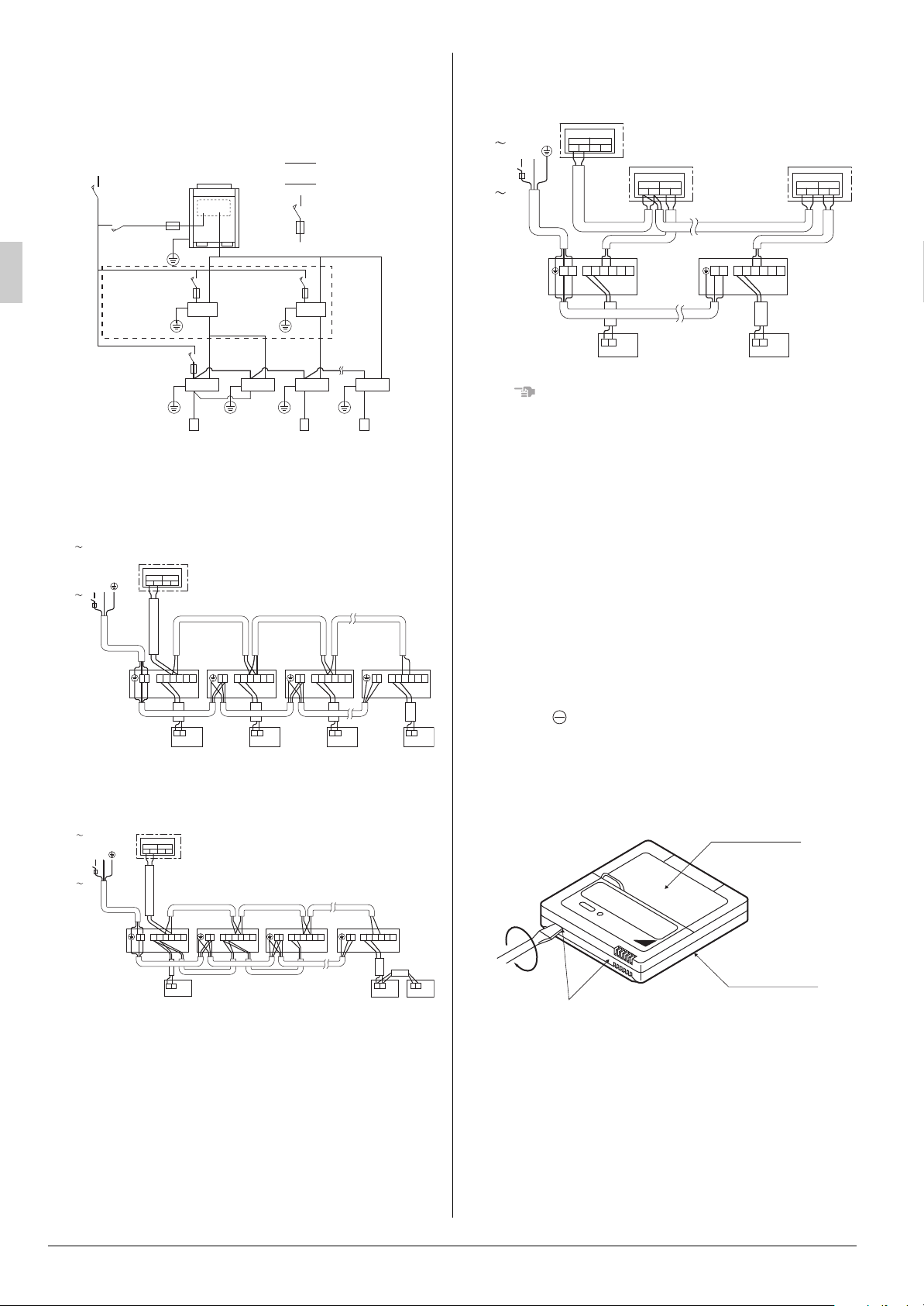
9-2 WIRING EXAMPLE
NOTE
Power supply wiring
Transmission wiring
Switch
Fuse
Power supply
Main
switch
Remote controller
Indoor unit
BS unit
(Only for Heat
recovery
system)
LN
IN/D OUT/D
F
1 F2 F1 F2
Control box
LN
P1P
2
P1P
2
F1F2T1T
2
P1P
2
P1P
2
F1F2T1T
2
LN
P1P
2
P1P
2
F1F2T1T
2
LN LN
P1P
2
P1P
2
F1F2T1T
2
Outdoor unit
No. 1 System
Indoor
unit A
Indoor
unit B
Indoor
unit C
Most
downstream
Indoor unit
Power supply
220-240V
50Hz
or
220V
60Hz
• Fit the power supply wiring of each unit with a switch and fuse
as shown in the drawing.
COMPLETE SYSTEM EXAMPLE (3 systems)
3. When including BS unit
Power
supply
220-240V
50Hz
or
220V
60Hz
LN
Outdoor unit
Control box
IN/D OUT/D
F
1F2F1F2
No. 3
System
BS unit
Control box
IN/DOUT/D
F
1F2F1F2
BS unit
Control box
IN/DOUT/D
F
1F2F1F2
1. When using 1 remote controller for 1 indoor unit. (Normal operation)
2. For group control or use with 2 remote controllers
Power supply
220-240V
50Hz
or
220V
60Hz
Outdoor unit
LN
Indoor unit A
Control box
IN/D OUT/D
F
1 F2 F1 F2
No. 2
System
Indoor unit B
LN
P1P
2
F1F2T1T
2 LNP1P2F1F2T1T2 LNP1P2F1F2T1T2 LNP1P2F1F2T1T2
Indoor unit C
Most
downstream
indoor unit
Indoor unit A
LN LN
P1P2F1F2T1T
2
P1P2F1F2T1T
Most
2
downstream
indoor unit
P1P
2
P1P
2
• It is not necessary to designate indoor unit address when
using group control. The address is automatically set when
power is activated.
[ PRECAUTIONS ]
1. A single switch can be used to supply power to units on the
same system. However, branch switches and branch circuit
breakers must be selected carefully.
2. Do not ground the equipment on gas pipes, water pipes or
lightning rods, or crossground with telephones. Improper
grounding could result in electric shock.
9-3
CONTROL BY 2 REMOTE CONTROLLERS (Controlling 1 indoor unit by 2 remote controllers)
• When using 2 remote controllers, one must be set to “MAIN”
and the other to “SUB”.
MAIN/SUB CHANGEOVER
(1) Insert a screw driver into the recess between the
upper and lower part of remote controller and, working
from the 2 positions, pry off the upper part.
The remote controller PC board is attached to the upper
part of remote controller.
Upper part of
remote controller
10 English
Lower part of
P1P
2
P1P
P1P
2
For use with 2
Fig. 6
remote controllers
2
Insert the screwdriver here and gently work
off the upper part of remote controller.
remote controller
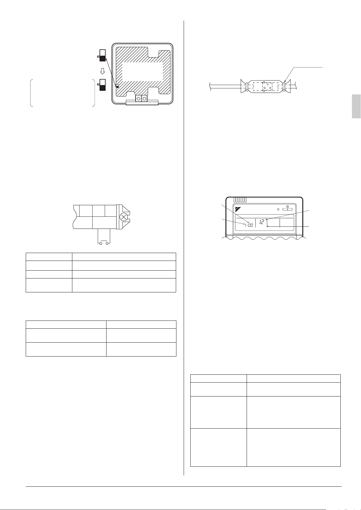
(2) Turn the MAIN/SUB changeover switch on one of the
Only one remote
controller needs to be
changed if factory
settings have remained
untouched.
(Factory setting)
S
M
S
S
M
Remote controller
PC board
SETTING
MODE NO.
SECOND
CODE NO.
FIELD SET
MODE
FIRST
CODE NO.
two remote controller PC boards to “S”.
(Leave the switch of the other remote controller set to “M”.)
Wiring Method (See ‘‘ELECTRIC WIRING WORK’’)
(3) Remove the electric parts box lid
(4) Add remote control 2 (slave) to the terminal block for
remote controller (P
, P2) in the electric parts box.
1
(There is no polarity.) (Refer to Fig. 6 and 8-3.)
9-4 COMPUTERISED CONTROL (FORCED OFF
AND ON/OFF OPERATION)
(1) Wire specifications and how to perform wiring
• Connect input from outside to terminals T1 and T2 of the
terminal block for remote controller.
2. Slide the insulation tube according to the arrow as shown in
fig. so that the connector can be completely covered.
3. Bind the opening of insulation tube with the attached clamp
material.
Clamp
(accessory)
11. FIELD SETTINGS
Make sure the electric parts box lids are closed on the
indoor and outdoor units.
Field setting must be made from the remote controller in
accordance with the installation condition.
• Setting can be made by changing the “Mode No.”, “FIRST
CODE NO.”, and “SECOND CODE NO.”.
• The “Field Settings” included with the remote control lists the
order of the settings and method of operation.
Setting is made in all units in a group. To set for individual
indoor units or to check the setting, use the mode Nos. (with
“2” in upper digit) in parentheses ( ).
Wire specification Sheathed vinyl cord or cable (2 wire)
Gauge
Length Max. 100 m
External terminal
(2) Actuation
• The following table explains FORCED OFF and ON/OFF
FORCED OFF ON/OFF OPERATION
Input “ON” stops operation (impossible
by remote controllers.)
Input OFF enables control by remote
controller.
(3) How to select FORCED OFF and ON/OFF OPERATION
• Turn the power on and then use the remote controller to
9-5 CENTRALIZED CONTROL
• For centralized control, it is necessary to designate the group
No. For details, refer to the manual of each optional controllers for centralized control.
10. DECORATION PANEL INSTALLATION
Refer to the installation manual of the panels.
[ CAUTION ]
SWING FLAP MOTOR WIRING METHOD
1. Connect two lead wires of swing flap motor mounted on the
decoration panel to the connectors of main body.
English 11
F2 T1 T2
FORCED
OFF
Input A
0.75 - 1.25 mm
Contact that can ensure the minimum applicable load of 15 V DC, 10 mA.
OPERATIONS in response to Input A.
select operation.
Input OFF
Input ON
2
ON turns ON unit.
OFF turns OFF unit.
• Set the remote controller to the field set mode. For
details, refer to the “HOW TO SET IN THE FIELD”, in the
remote controller manual.
• When in the field set mode, select mode No. 12, then set
the first code (switch) No. to “1”. Then set second code
(position) No. to “01” for FORCED OFF and “02” for ON/
OFF OPERATION. (FORCED OFF at factory set)
12. TEST OPERATION
Refer to the installation manual of the outdoor unit.
• The operation lamp of the remote controller will flash when
an malfunction occurs. Check the malfunction code on the
liquid crystal display to identify the point of trouble. An explanation of malfunction codes and the corresponding trouble is
provided in “CAUTION FOR SERVICING” of the outdoor unit.
If any of the items in Table 6 are displayed, there may be a
problem with the wiring or power, so check the wiring again.
Tabl e 6
Remote control display Content
“Concentrated Management” is lit up
“U4” is lit up
“UH” is lit up
No display
• There is a short circuit at the FORCED
OFF terminals (T1, T2)
• The power on the outdoor unit is off.
• The outdoor unit has not been wired for
power supply.
• Incorrect wiring for the transmission
wiring and / or FORCED OFF wiring.
• The power on the indoor unit is off.
• The indoor unit has not been wired for
power supply.
• Incorrect wiring for the remote controller wiring, the transmission wiring and /
or the FORCED OFF wiring.

3P258319-5K EM02A084C
(1511) HT
 Loading...