

Daikin FWF02AATNMV1, FWF03AATNMV1, FWF04AATNMV1 Installation manuals
INSTALLATION
MANUAL
Models
FWF02AATNMV1
FWF03AATNMV1
FWF04AATNMV1
Installation Manual
Chilled Water Fan Coil Units
Installationshandbuch
Kaltwasser-Ventilatorluftkühler
Manuel d’installation
Ventilo-convecteur à eau glacée
Installatiehandboek
Koudwater-Ventilatorluchtkoeler
Manual de instalación
Unidades de serpentín de ventilador de agua fría
Manuale Di Installazione
Unità fan coil ad acqua fredda
Εγχειρίδιο εγκατάστασης
Μονάδες πηνίου του ανεμιστήρα για το παγωμένο νερ
English
Deutsch
Français
Nederlands
Español
Italiano
Ελληνικά
Manual De Instalação
Unidades de bobina de ventilador de água refrigerada
Руководство По Установке
Вентиляторные доводчики с водяным охлаждением
Kurulum Kılavuzu
So¤uk su fan bobin üniteleri
Portugues
Русский
Türkçe

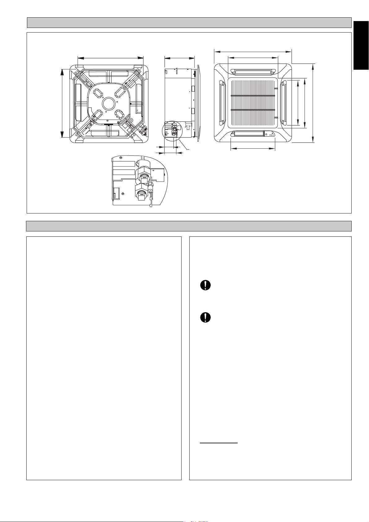
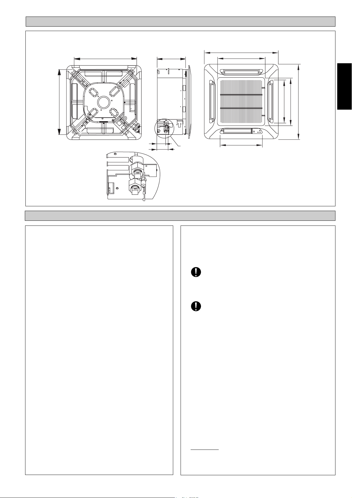
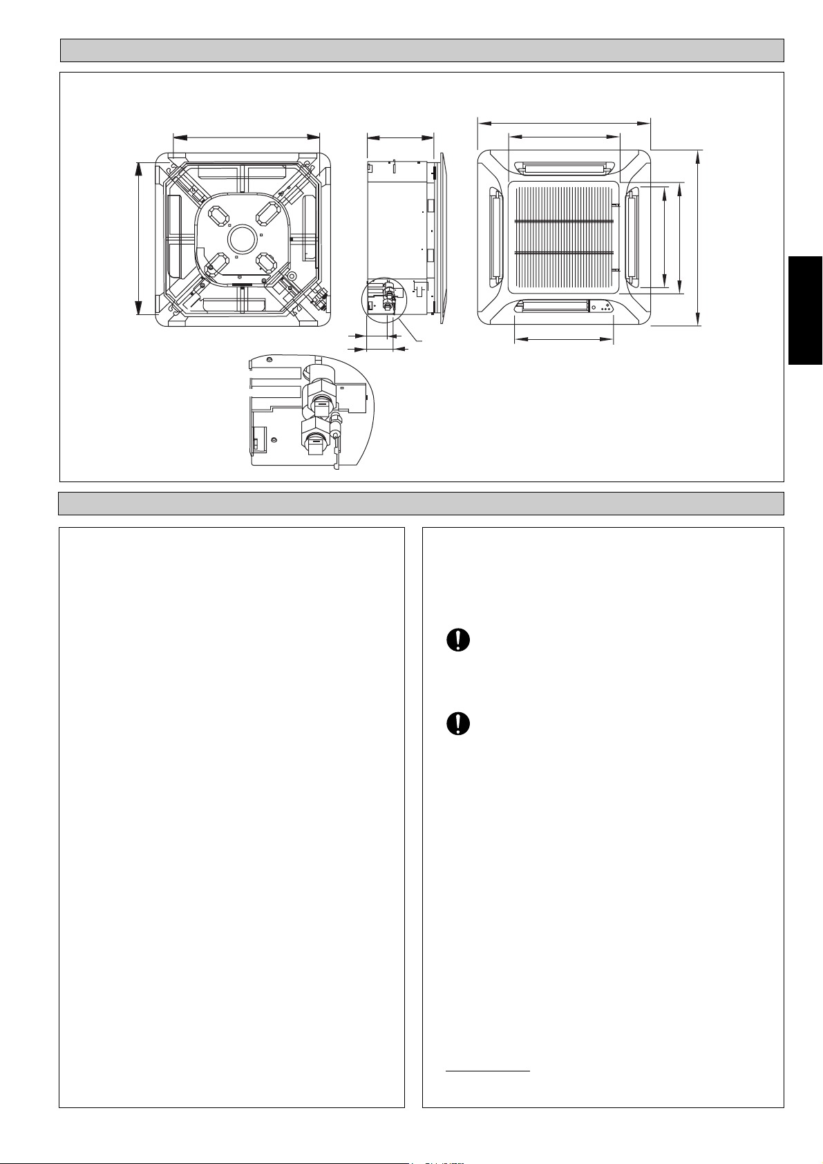
OUTLINE AND DIMENSIONS
Indoor Unit: FWF02AAYNMV1 / FWF03AATNMV1 / FWF04AATNMV1
570
570
250
640
408
364
408
English
640
75
98
WATER INLET
WATER OUTLET
SAFETY PRECAUTIONS
! WARNING
• Installation and maintenance should be performed by
qualified persons who are familiar with local code and
regulation, and experienced with this type of appliance.
• All field wiring must be installed in accordance with the
national wiring regulation.
• Ensure that the rated voltage of the unit corresponds to
that of the name plate before commencing wiring work
according to the wiring diagram.
• The unit must be GROUNDED to prevent possible hazard
due to insulation failure.
• All electrical wiring must not touch the water piping or
any moving parts of the fan motors.
• Confirm that the unit has been switched OFF before
installing or servicing the unit.
• Risk of electric shock, can cause injury or death.
Disconnect all remain electric power supplies before
servicing.
• DO NOT pull out the power cord when the power is ON.
This may cause serious electrical shocks which may result
in the fire hazards.
• Keep the indoor and outdoor units, power cable and
transmission wiring, at least 1m from TVs and radios, to
prevent distorted pictures and static. {Depending on the
type and source of the electrical waves, static may be heard
even when more than 1m away}.
SEE DETAIL A
DETAIL A
364
All dimensions are in mm/ (in)
! CAUTION
Please take note of the following important points when
installing.
• Ensure that drainage piping is connected properly.
If the drainage piping is not connected properly, it may
cause water leakage which will dampen the furniture.
• Ensure that the unit’s panel is closed after service or
installation.
Unsecured panels will cause the unit to operate noisily.
• Air swing connector and LED wire connector shall be
inside the control box.
• Sharp edges and coil surfaces are potential locations which
may cause injury hazards. Avoid from being in contact
with these places.
• Before turning off the power supply set the remote
controller’s ON/OFF switch to the “OFF” position to
prevent the nuisance tripping of the unit. If this is not done,
the unit’s fans will start turning automatically when power
resumes, posing a hazard to service personnel or the user.
• Do not operate any heating apparatus too close to the air
conditioner unit. This may cause the plastic panel to melt or
deform as a result of the excessive heat.
• Ensure the color of wires of the outdoor unit and the
terminal markings are same to the indoors respectively.
• IMPORTANT : DO NOT INSTALL OR USE THE AIR
CONDITIONER UNIT IN A LAUNDRY ROOM.
1
NOTICE
Disposal requirements
Your air conditioning product is marked with this symbol. This means that electrical and electronic products shall not
be mixed with unsorted household waste.
Do not try to dismantle the system yourself: the dismantling of the air conditioning system, treatment of the refrigerant, of oil and of other parts must be done by a qualified installer in accordance with relevant local and national
legislation.
Air conditioners must be treated at a specialized treatment facility for re-use, recycling and recovery. By ensuring this
product is disposed of correctly, you will help to prevent potential negative consequences for the environment and
human health. Please contact the installer or local authority for more information.
Batteries must be removed from the remote controller and disposed of separately in accordance with relevant local
and national legislation.
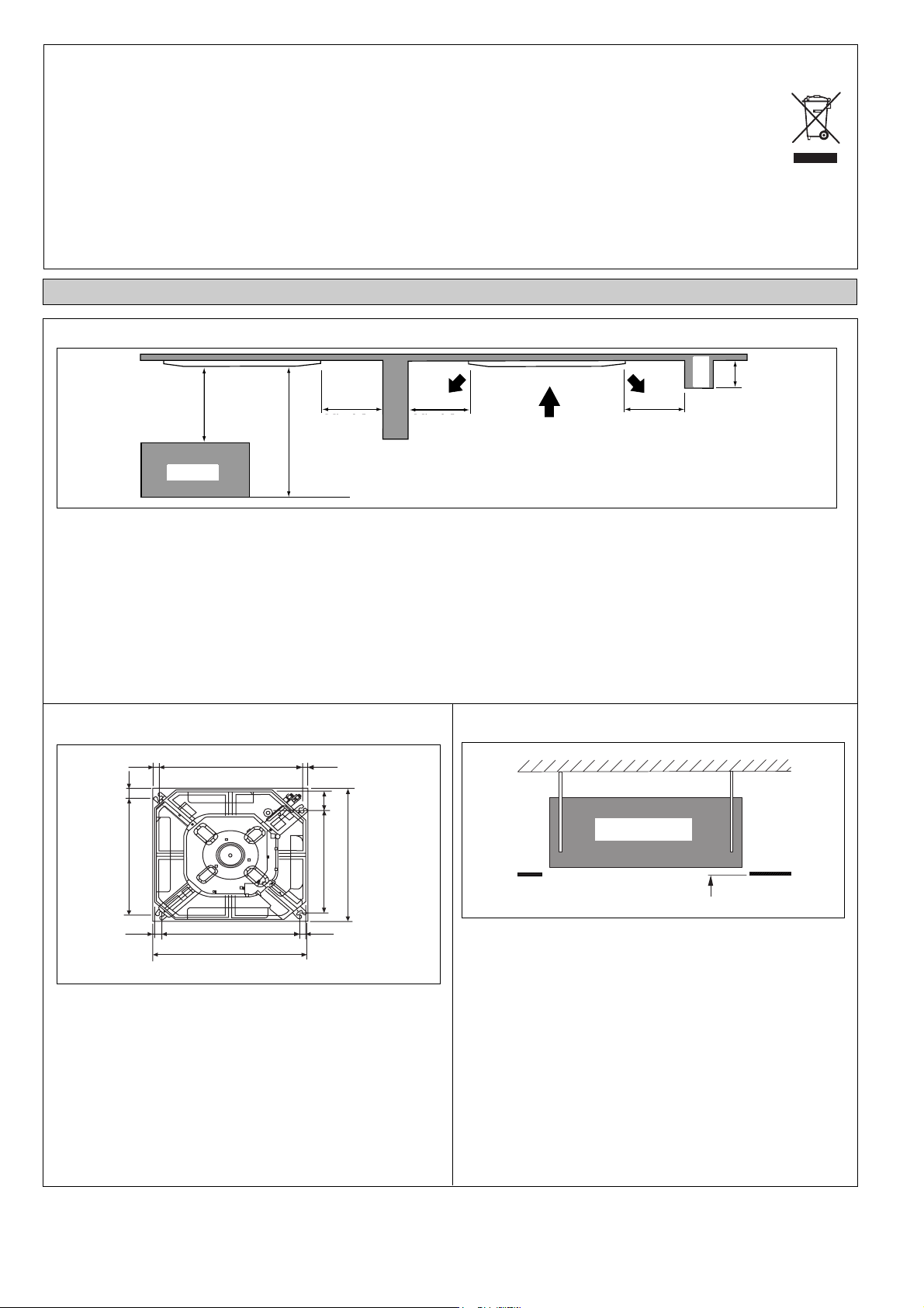
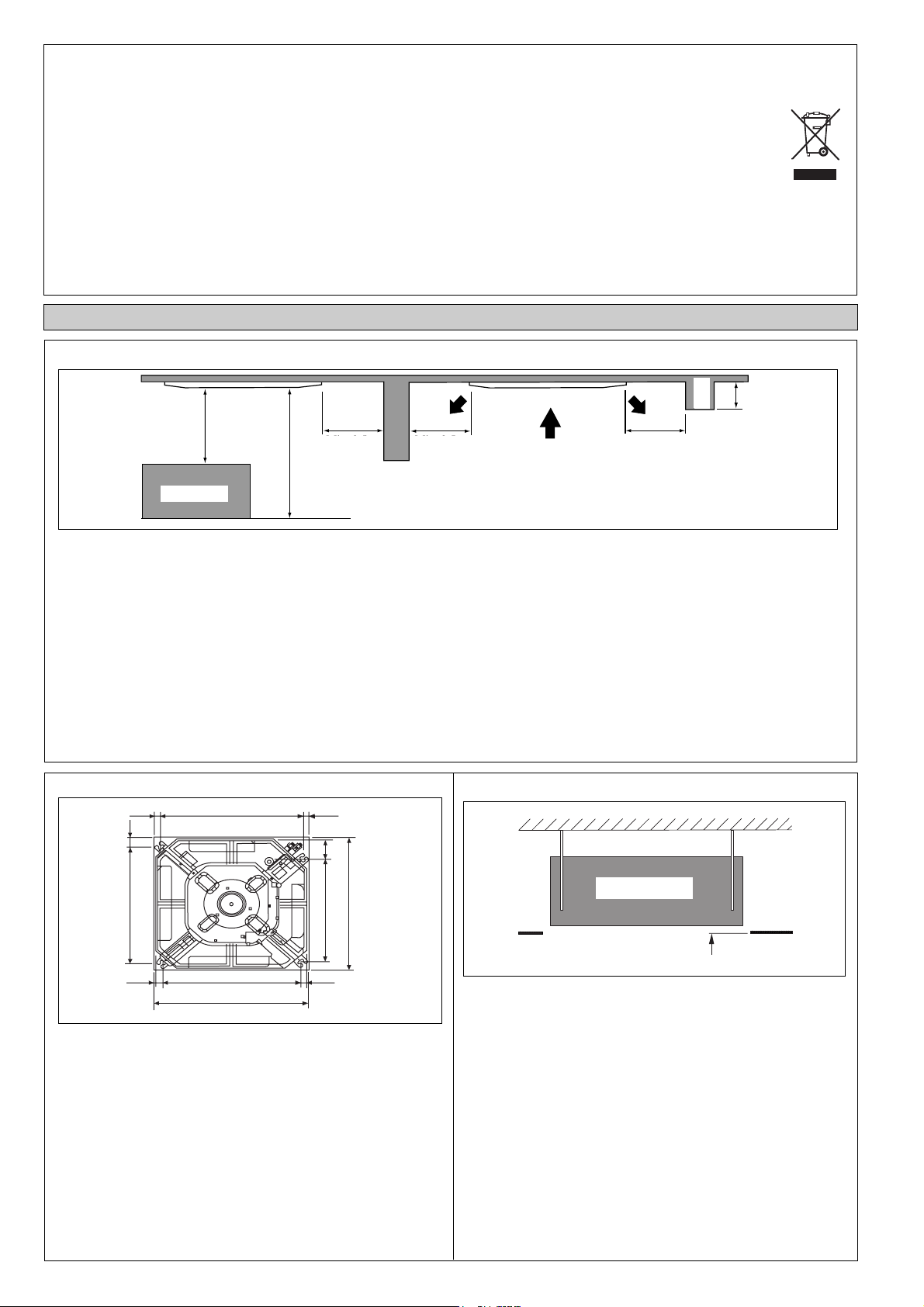
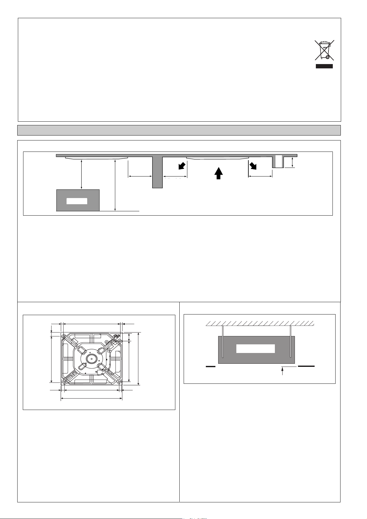
INSTALLATION OF THE INDOOR UNIT
1. Preliminary Site Survey
Beam
Beam
Min. 1.0 m
Min. 1.0 m
Obstacle
Obstacle
Min. 0.5 m
Min. 0.5 m
Max. 3.0 m
Min. 2.5m ~ Max 3.0m
Floor
Floor
Min. 0.5 m
Min. 0.5 m
Min. 0.5 m
Min. 0.5 m
Max. 0.3 m
Max. 0.3 m
• Electrical supply and installation is to conform to local authority’s (e.g. National Electrical Board) codes and regulations.
• Voltage supply fluctuation must not exceed ±10% of rated voltage. Electricity supply lines must be independent of welding
transformers which can cause high supply fluctuation.
• Ensure that the location is convenient for wiring, piping and drainage.
• The indoor unit must be installed in such that is free from any obstacles in path of cool air discharge and warm air return, and
must allow spreading of air throughout the room (near the center of the room).
• Provide clearance for the indoor unit from the wall and obstacles as shown in the figure.
• The installation place must be strong enough to support a load 4 times the indoor unit weight to avoid amplifying noise and
vibration.
• The installation place (hanging ceiling surface) must levelled and the height in the ceiling is 350mm or more.
• The indoor unit must be away from heat and steam sources (avoid installing it near an entrance).
2. Unit Installation
15.0 538.0
38.0
505.0
32.0
580.0 ~ 610.0 mm (Ceiling Board Opening)
529.0 19.0
18.0
88.0
448.0
Board Opening)
580.0 ~ 610.0 mm (Ceiling
• Measure and mark the position for the hanging rod. Drill the
hole for the angle nut on the ceiling and fix the hanging rod.
• The installation template is extended according to temperature and humidity. Check on dimensions in use.
• The dimensions of the installation template are the same as
those of the ceiling opening dimensions.
• Before ceiling laminating work is completed, be sure to fit
3. Unit Hanging
Indoor Unit
Indoor Unit
Ceiling
Ceiling
Board
Board
35.0 mm
35.0 mm
• Confirm the pitch of the hanging rod.
• Hold the unit and hang it on the hanging rod with the nut and
washer.
• Adjust the unit height to 35.0 mm between the indoor unit
bottom surface and the ceiling surface.
• Confirm with a level gauge that the unit is installed horizontally and tighten the nut and bolt to prevent unit failing and
vibration.
• Open the ceiling board along the outer edge of the paper
installation template.
the installation template to the indoor unit.
Note: Be sure to discuss the ceiling drilling work with the in-
stallers concerned.
2
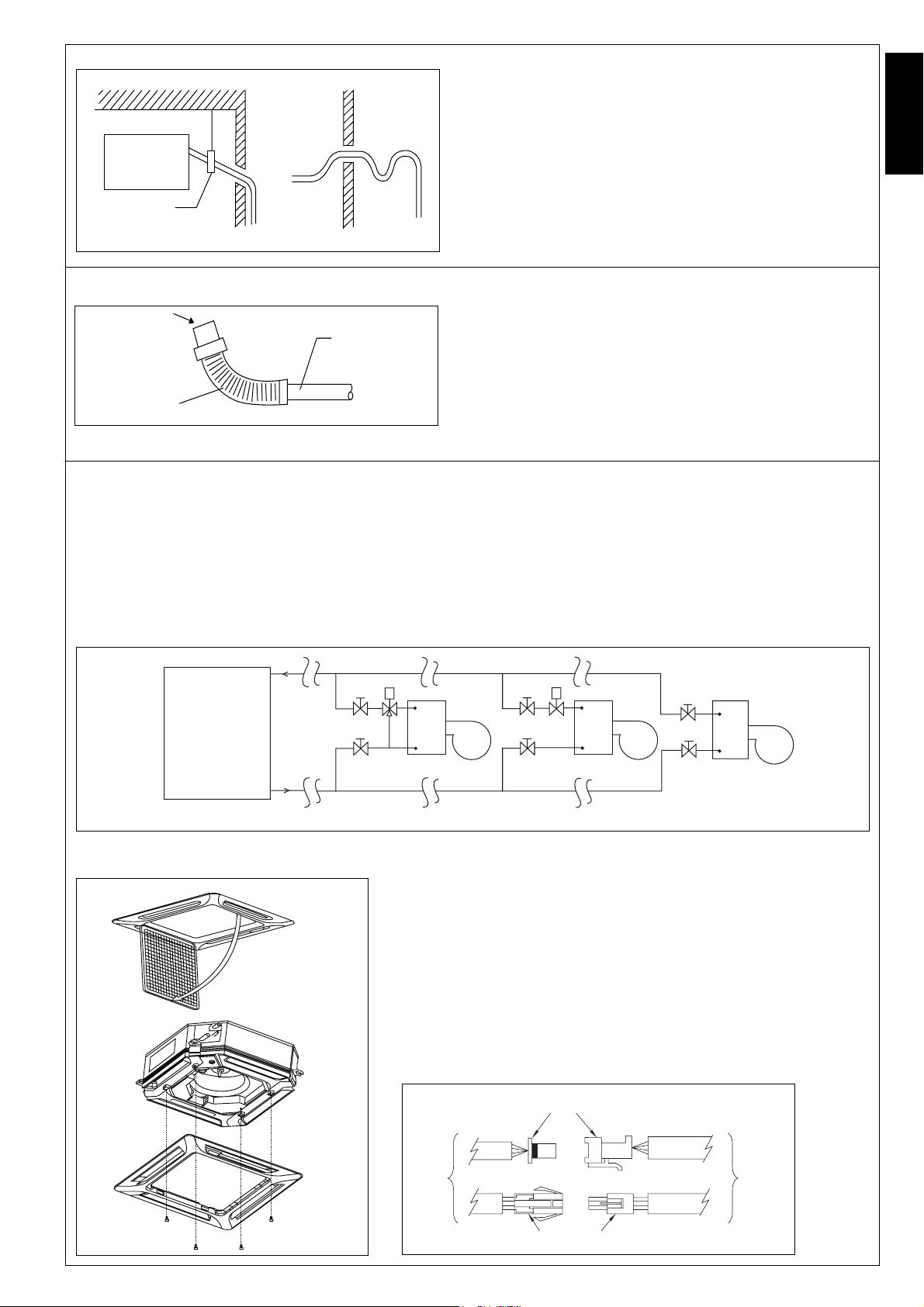
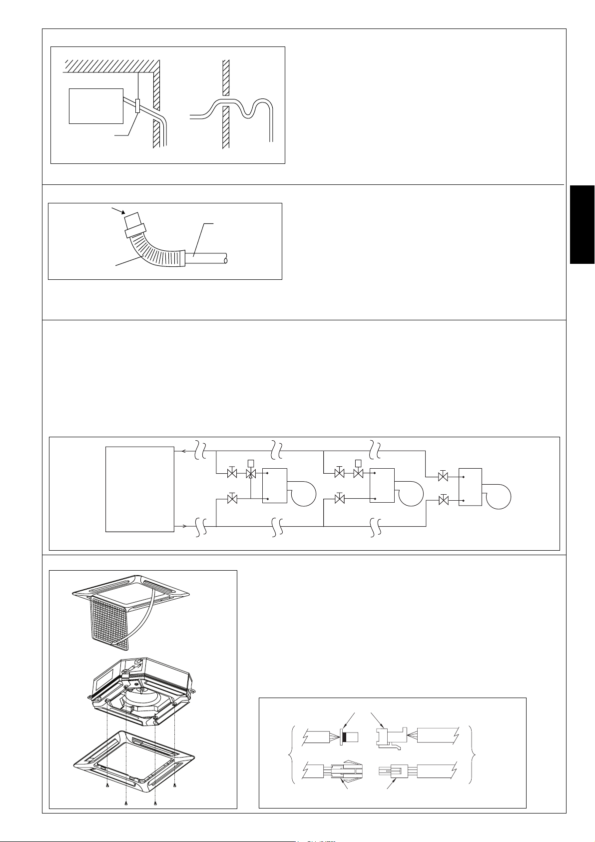
4. Drain Pump Work
Indoor Unit
Pipe Clamp
Good
Bad
• Drain pipe must be in downward gradient for smooth drainage.
• Avoid installing the drain pipe in up and down slope to prevent reversed water flow.
• During the drain pipe connection, be careful not to exert extra
force on the drain connector at indoor unit.
• The outside diameter of the drain connection at the flexible
drain hose is 20mm.
• Be sure to execute heat insulation (polyethylene foam with
thickness more than 8.0mm) on the drain piping to avoid the
condensed water dripping inside the room.
English
5. Drain Test
Feed Water
Main Drain Pipe
• Connect the main drain pipe to the flexible drain.
• Feed water from flexible drain hose to check the piping for leakage.
• When the test is completed, connect the flexible drain hose to the
drain connector on the indoor unit.
Flexible Drain Hose
Note: This Indoor Unit uses a drain pump for condensed water
drainage. Install the unit horizontally to prevent water leakage or condensation around the air outlet.
6. Water Piping Connection
• The indoor unit is equipped with water outlet and inlet connection. There is an air-vent that is fitted along with the connection
for air purging.
• 3 ways valve is required for cycling off or bypass the chilled water.
• Black steel pipe, polyethrene pipe and copper tube are recommended in the field installation. All types of piping and connection must be insulated with polyethrene (ARMAFLEX type or equivalent) to avoid condensation.
• Do not used contaminated or damaged pipe and fitting for installation.
• Some main fitting components are needed in the system to enhance the capacity and ease the service, such as gate valve,
balancing valve, 2 ways or 3 ways valve, filter, strainer and etc.
Gate Valve
2 Way Valve
FCUFCU
Gate Valve
FCU
Chiller
Gate Valve
3 Way Valve
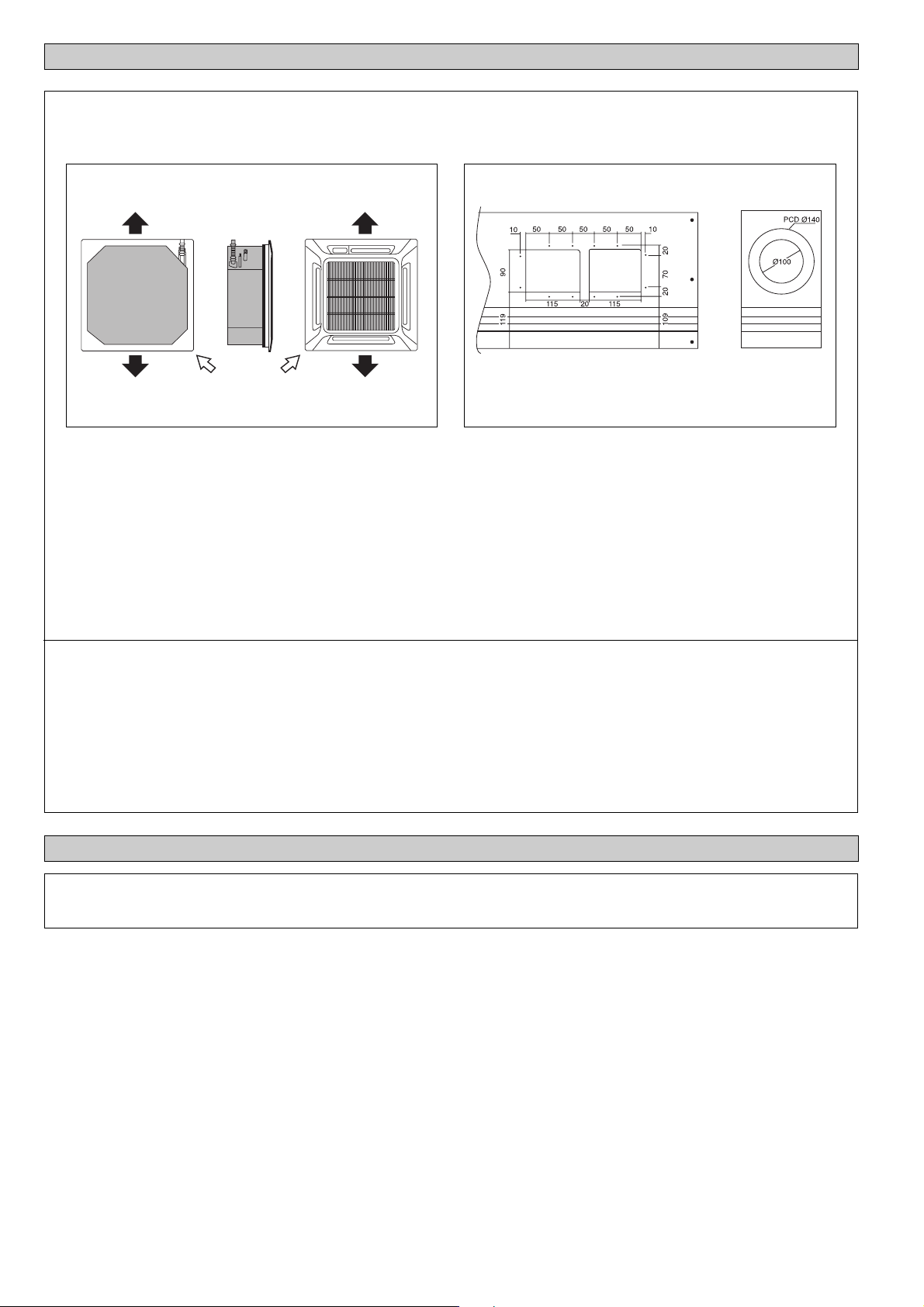
7. Panel Installation
OPEN
Screw
Gate ValveGate Valve
Good Control Bad Control Worst Control
Gate Valve
• Be sure to remove the installation template before installing the
front panel.
• Open the air intake grille by pulling back the catchers and removing it together with filter from panel.
• Install the front frame panel onto the indoor unit by 4 screws and
tighten it completely to prevent cool air leakage.
• Connect the LED wire and air swing wire to the indoor unit.
Note: Install the front panel firmly to prevent cool air leakage which
will cause condensation and water dripping.
LED Wire
From
Front
Panel
Air Swing Wire
From
Control
Box
3
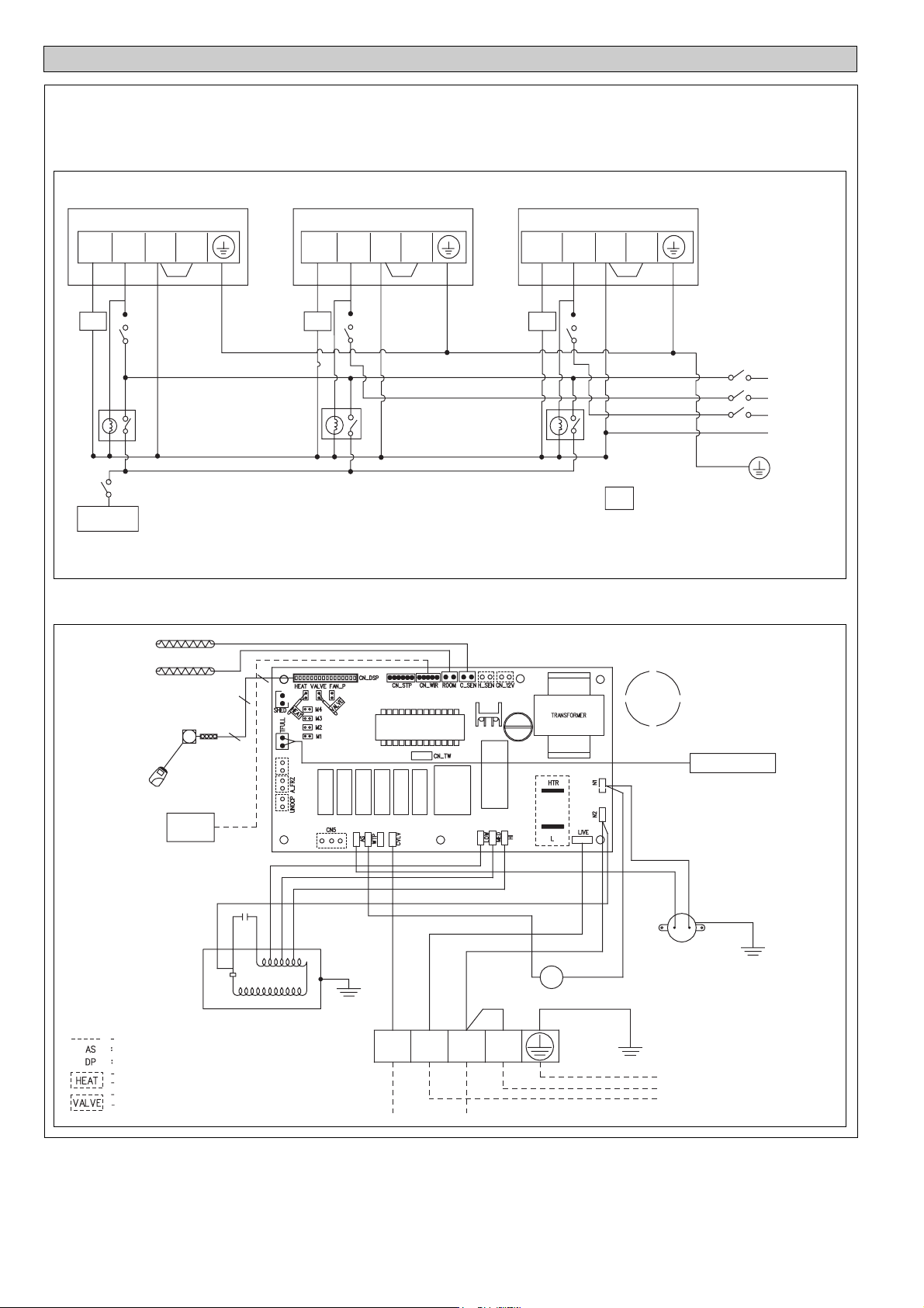
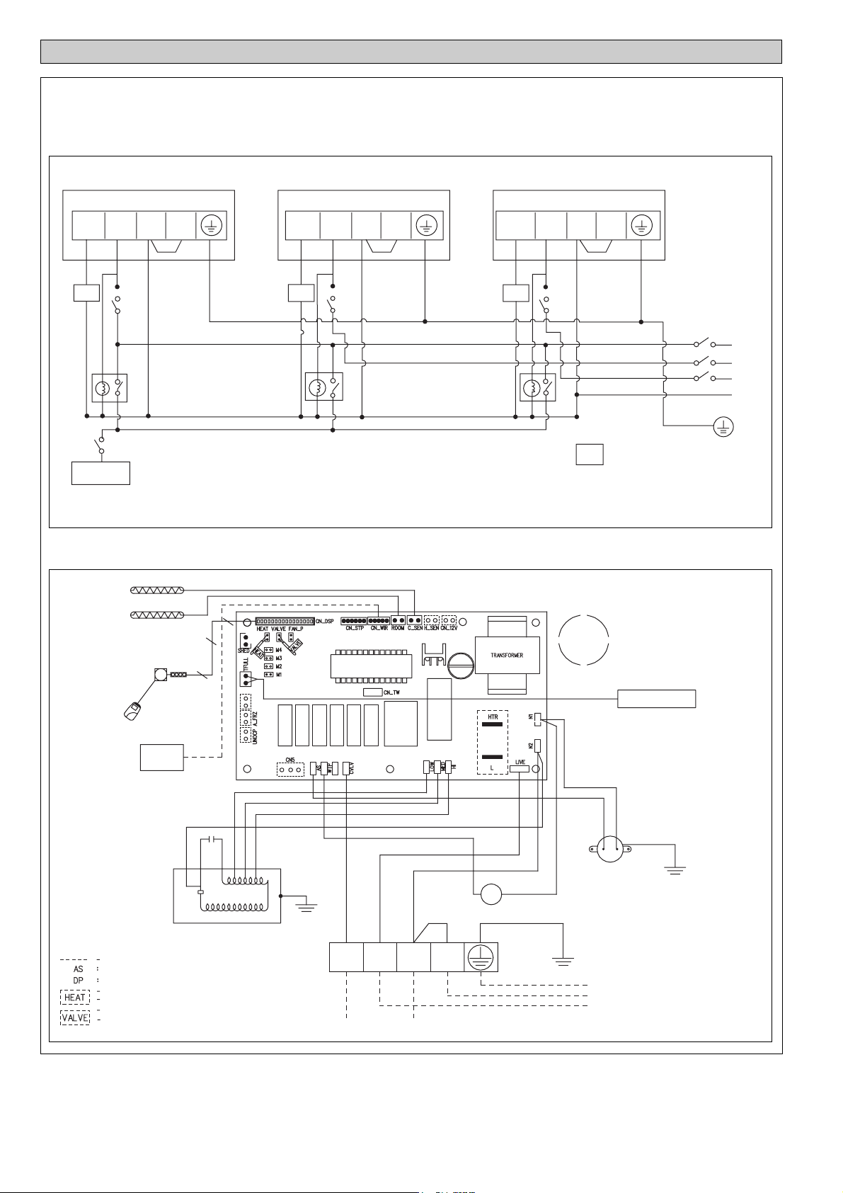
ELECTRICAL WIRING CONNECTION
This is proposed wiring connection. It may change subject to the chiller unit and must comply with the local and national code and
regulations.
Model: FWF02AATNMV1 / FWF03AATNMV1 / FWF04AATNMV1
MODEL: CK10/15/20CW
FCU 2
VALVE L/L1
FCU 1
N/L2 N/L2
VALVE L/L1 N/L2 N/L2
3WV 3WV
X1 X2 X3
Chiller
Model: FWF02AATNMV1 / FWF03AATNMV1 / FWF04AATNMV1
INDOOR COIL SENSOR
RETURN AIR SENSOR
LED/IR RECEIVER
16
9
10
FCU 3
VALVE L/L1 N/L2 N/L2
3WV
3WV
X1, X2, X3
200-240V/1 /50Hz
208-230V/1 /60Hz
3 way valve
Relay (220-240V,10A)
Relay (220-240V, 10A)
PART NUMBER: 08024091944
R
S
T
N
LCD WIRELESS
CAUTION !
FIELD SUPPLY WIRING
AIR SWING MOTOR
DRAIN PUMP
WITH JUMPER FOR HEAT PUMP
WITHOUT JUMPER FOR COOLING
WITH JUMPER FOR VALVE APPLICATION
WITHOUT JUMPER FOR VALVELESS APPLICATION
CONTROLLER
WIRED
CONTROLLER
BLACK
WHITE
RED
AC LC
MC
FAN MOTOR
ORANGE FL
BROWN FM
YELLOW FH
PURPLE
RED
VALVE L/L1 N/L2 N/L2
TO 3 WAY VALVE
Note : Unit comes in standard heatpump and for valve application.
BLACK
BLACK
BLUE
DP
G/Y
BLUE
BLACK
RED
AS
E
N
1 PHASE 50Hz
L
FLOAT SWITCH
G/Y
220~240V
4
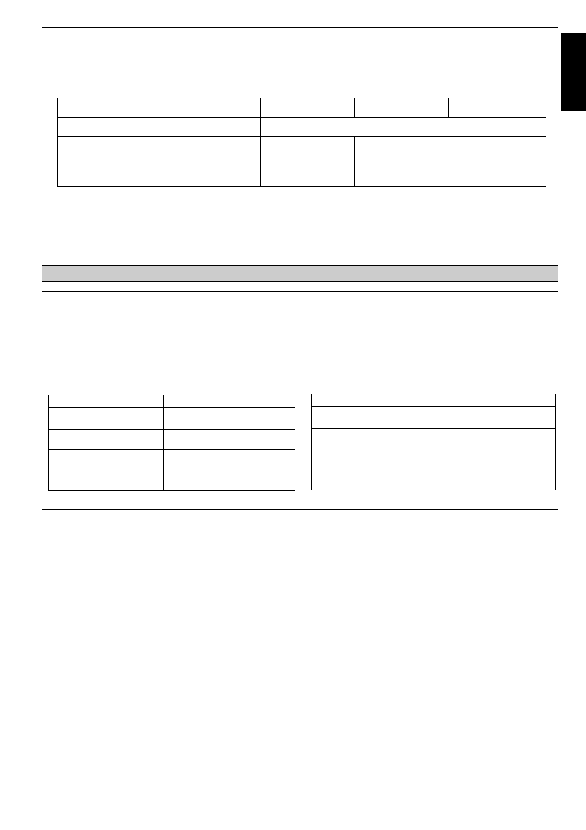
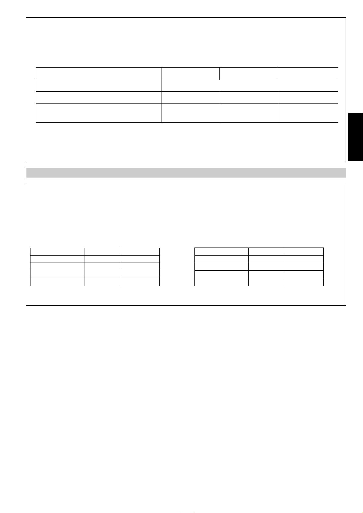
IMPORTANT : * These values are for information only. They should be checked and selected to comply with local and/or
national codes and regulations. They are also subject to the type of installation and size of conductors.
** The appropriate voltage range should be checked with label data on the unit.
A main switch or other means for disconnection, having a contact separation in all poles, must be incorporated in the fixed wiring in accordance with relevant local and national legislation.
Model FWF02AATNMV1 FWF03AATNMV1 FWF04AATNMV1
English
Voltage range**
220V-240V/1Ph/50Hz+!
Recommended fuse* A 222
Power supply cable size* mm
2
1.5 1.5 1.5
Number of conductors 333
• All wires must be firmly connected.
• All wires must not touch the water piping, or any moving parts of the fan motor.
• The power supply cord must be equivalent to H05VV-F (60227 IEC 52 or 60227 IEC 53) which is the minimum requirement,
and to be used in protective tube.
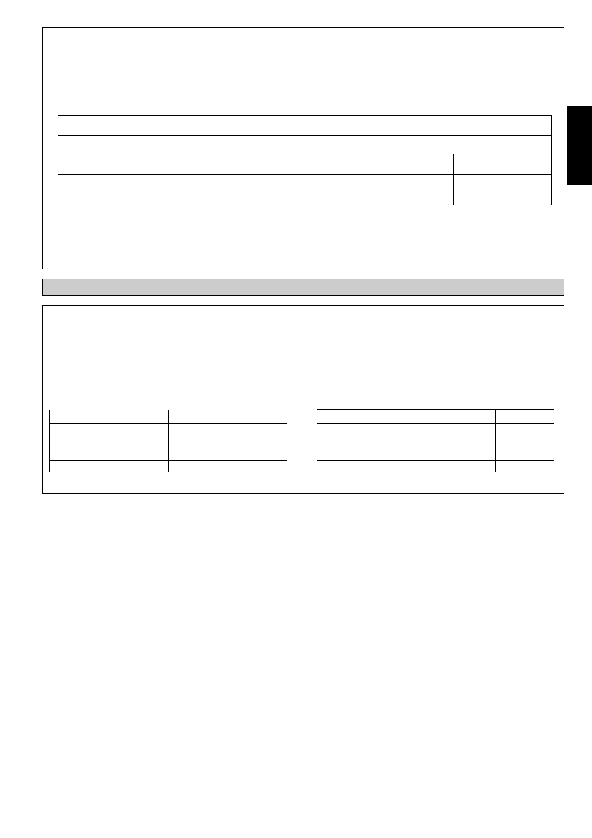
OPERATING RANGE
Operating Limits:
Thermal carrier : Water
Water temperature : 5 ~50°C
Maximum water pressure : 16 bar
Air temperature : (as below)
Cooling Mode
Temperature Ts °C/°F Th °C/°F
Minimum indoor
temperature
Maximum indoor
temperature
Minimum outdoor
temperature
Maximum outdoor
temperature
16.0 / 60.8 11.0 / 51.8
32.0 / 89.6 23.0 / 73.4
16.0 / 60.8 -
46.0 / 114.8 -
Heating Mode
Temperature Ts °C/°F Th °C/°F
Minimum indoor
temperature
Maximum indoor
temperature
Minimum outdoor
temperature
Maximum outdoor
temperature
16.0 / 60.8 -
30.0 / 86.0 -
-5.0 / 23.0 -6.0 / 21.2
24.0 / 75.2 18.0 / 64.4
Ts: Dry bulb temperature. Th: Wet bulb temperature.
5
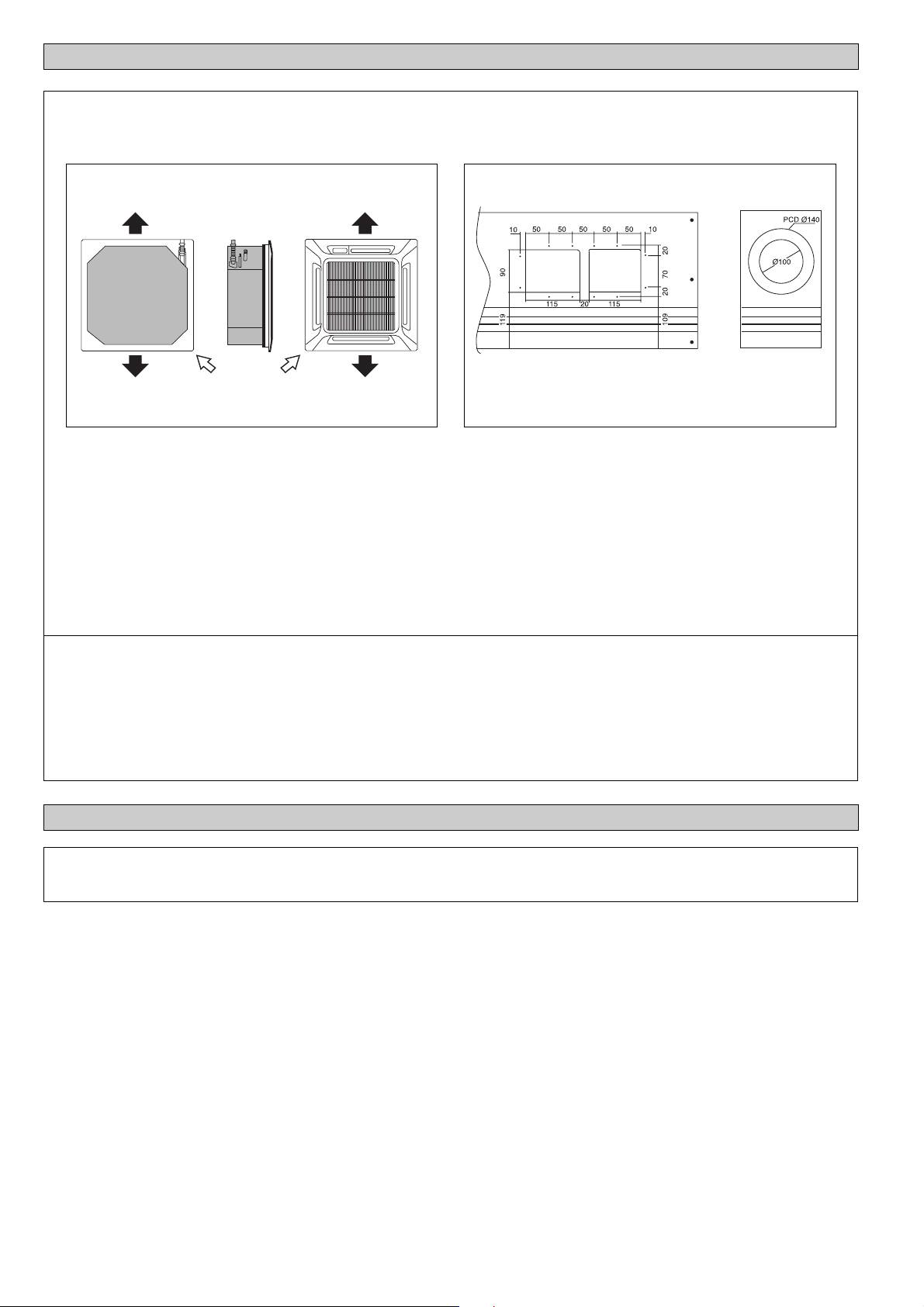
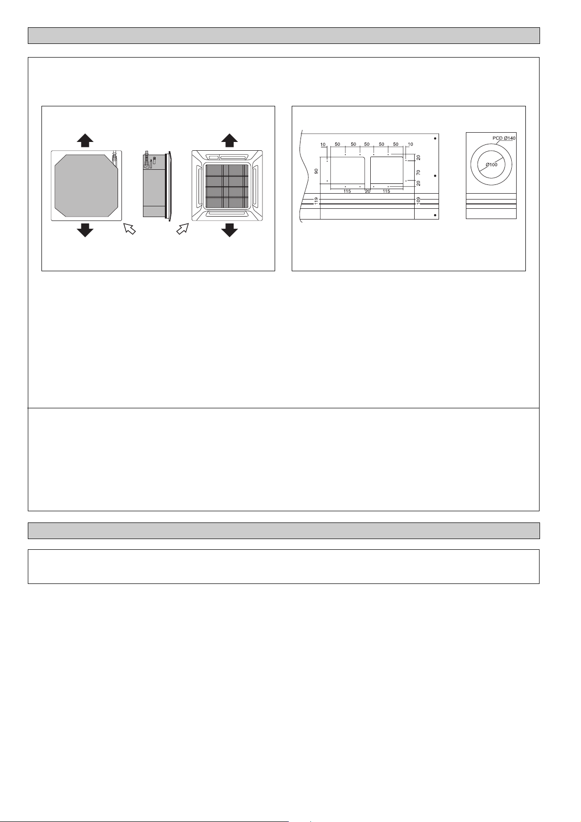
1. Short Duct Specification
ACCESSORY PARTS
Possible Direction For Air Discharge And Air Intake
Air DischargeAir Discharge
Air Discharge Air Discharge
• The indoor unit is provided with air discharge and air intake “knock-out” hole for duct connection. However the connection of
the short duct for air discharge is possible on only one side.
• The use of short duct for air discharge will improve airflow distribution if there is an obstruction (such as a lighting fixture) or
in a long, narrow room or an L-shaped room. It also use for air-conditioning of two rooms simultaneously.
Note:
• Avoid using the short duct on which the air discharge grille can be completely closed, to prevent evaporator freezing.
• In order to prevent condensation forming, be sure that there is sufficient thermal insulation and no leakage of cool air when
installing the short duct.
• Keep the introduction of fresh air intake within 20% of total air flow. Also provide a chamber and use a booster fan.
Air Intake
Possible Opening Dimension For Duct Connection
Air Discharge Knock Out Hole
Air Intake
Knock Out
Hole
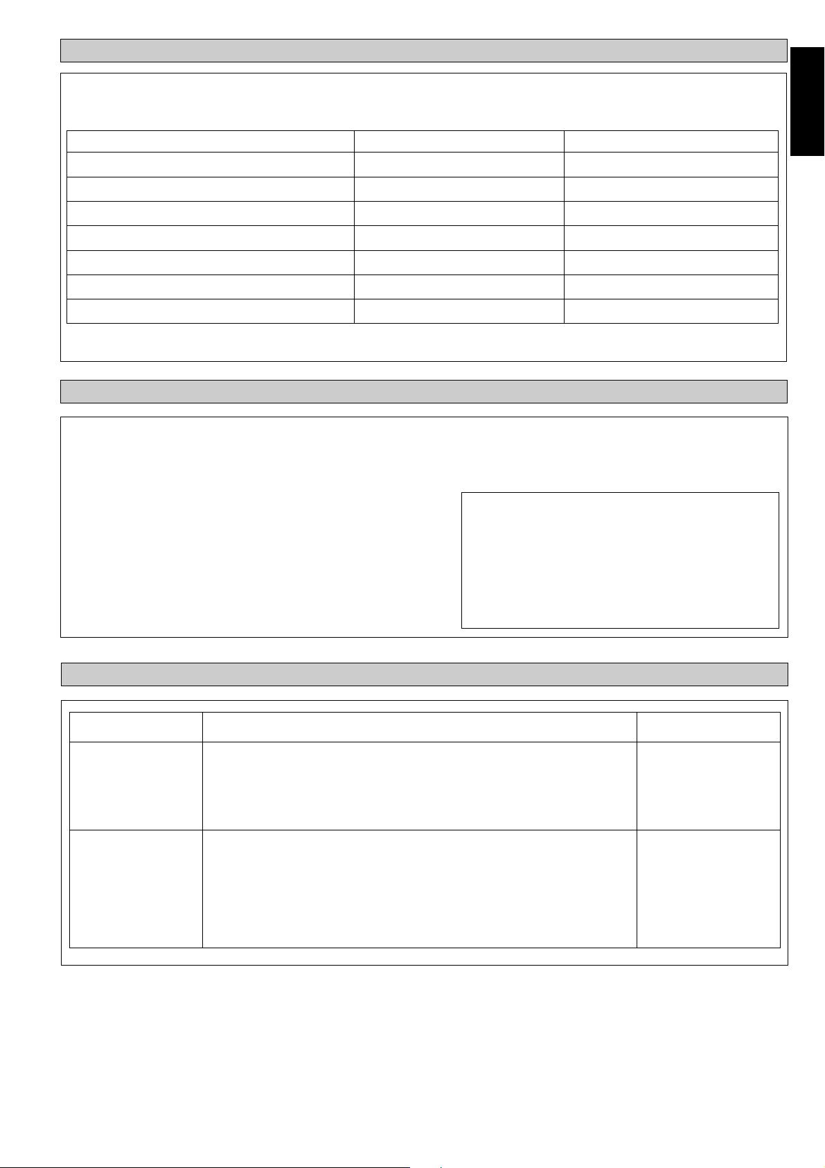
2. Sealing Material
• It is possible to seal one of the four air discharge outlet. (Sealing two or more air discharge outlet could cause a malfunction).
• Remove the front panel and insert the sealing material into the air discharge outlet on the indoor unit to seal the air outlet.
• The sealing material is the same length as the longer air discharge outlet. If it is desired to seal the shorter air discharge outlet,
cut the sealing material to shorten it.
• Push the sealing material in about 10mm beyond the bottom surface of the indoor unit so that it does not touch the air louver.
Be sure not to push the sealing material in any farther than about 10mm.
AUTO RANDOM RE-START FUNCTION
If there is a power cut when the unit is operating, it will automatically resume the same operating mode when the power is
restored. (Applicable only to units with this feature).
6
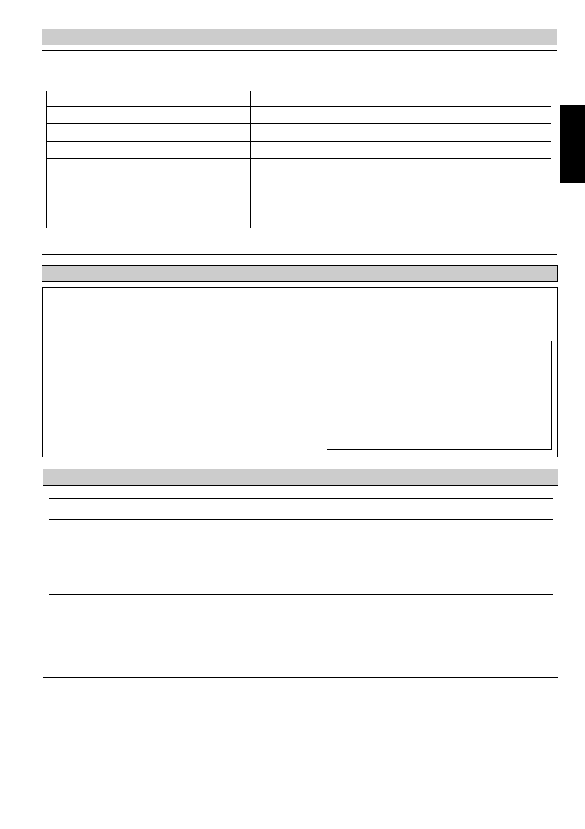
INDICATOR LIGHTS
Remote Control
When there is infrared remote control operating signal, the signal receiver on indoor unit will make a <beep> for signal
acceptance confirmation.
Error Description Cool LED Error Indication
Room sensor error 1 blink E1
Pipe water sensor error 2 blinks E2
Water pump error 6 blinks E6
Pipe water temperature fault 5 blinks E5
*Window open activated 3 blinks -
*Antifreeze mode activated 7 blinks -
English
*Load shedding activated 8 blinks
*Only applicable for 4-pipe system
OVERALL CHECKING
• Ensure the following, in particular:-
1. The unit is mounted solidly and rigid in position.
2. Piping and connections are leak proof.
3. Proper wiring has been done.
• Drainage check:- Pour some water into left side of drain pan (drainage are
in right side of unit).
• Test run:
1. Conduct a test run after water drainage test and gas leakage test.
2. Watch out for the following:
a) Is the electric plug firmly inserted into the socket?
b) Is there any abnormal sound from unit?
c) Is there any abnormal vibration on the unit itself or piping?
d) Is the drainage of water smooth?
Note:
• The installation guide above covers only the fan coil unit.
• The installation of fan coil unit may vary accordingly to
• Installation must be done by qualified personnel who are
SERVICE AND MAINTENANCE
-
For installation of outdoor (mini chiller etc) please refer
to the installation guide for such unit.
the type of outdoor unit.
familiar with this type of product.
Service Parts
Indoor air filter
Indoor unit
Maintenance Procedures
1. Remove any dust adhering to the filter by using a vacuum cleaner or wash
in lukewarm water (below 40°C/104°F) with a neutral cleaning detergent.
2. Rinse the filter well and dry before placing it back onto the unit.
3. Do not use gasoline, volatile substances or chemicals to clean the filter.
1. Clean any dirt or dust on the grille or panel by wiping it with a soft cloth
soaked in lukewarm water (below 40°C/104°F) and a neutral detergent
solution.
2. Do not use gasoline, volatile substances or chemicals to clean the indoor
unit.
Period
At least once every
2 weeks.
More frequently if
necessary.
At least once every
2 weeks.
More frequently if
necessary.
7
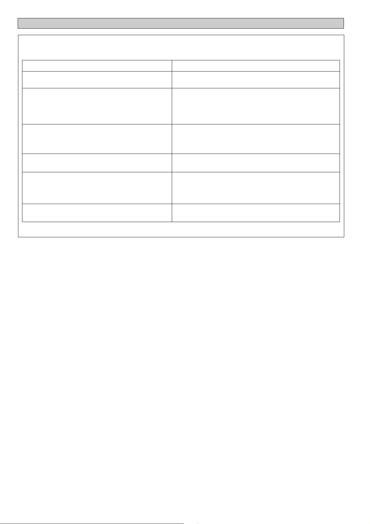
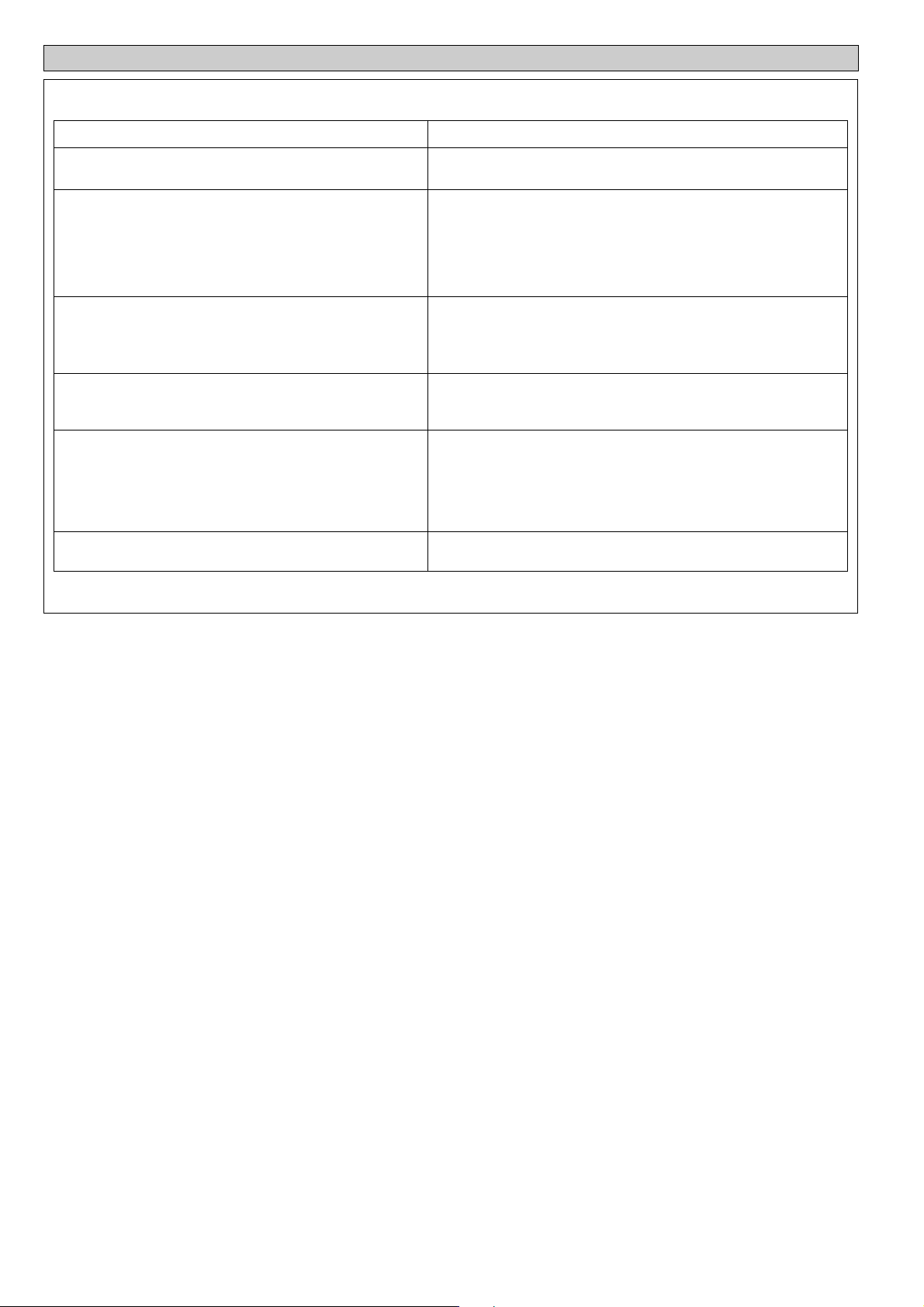
TROUBLESHOOTING
If any malfunction of the air conditioner unit is noted, immediately switch off the power supply to the unit. Check the
following fault conditions and causes for some simple troubleshooting tips.
Fault
1. The compressor does not operate 3 minutes after the
air conditioner unit is started.
2. The air conditioner unit does not operate.
3. The air flow is too low.
4. Discharge air flow has bad odor.
5. Condensation on the front air grille of the indoor unit.
6. Water flowing out from the air conditioner unit.
If the fault persists, please call your local dealer / serviceman.
- Protection against frequent starting. Wait for 3 to 4 minutes
- Power failure, or the fuse need to be replaced.
- The power plug is disconnected.
- It is possible that your delay timer has been set incorrectly.
- If the fault persist after all these verifications, please contact
- The air filter is dirty.
- The doors or windows are open.
- The air suction and discharge are clogged.
- The regulated temperature is not high enough.
- Odours may be caused by cigarettes, smoke particles,
- This is caused by air humidity after an extended long period
- The set temperature is too low, increase the temperature
- Switch off unit and call dealer.
Causes / Action
for the compressor to start operating.
the air conditioner unit installer.
perfume etc. which might have adhered onto the coil.
of operation.
setting and operate the unit at high fan speed.
8
AUSLEGUNG UND ABMESSUNG
Innen-Gerät: FWF02AAYNMV1 / FWF03AATNMV1 / FWF04AATNMV1
570
570
WASSEREINTRITTSÖFFNUNG
WASSERAUSTRITTSÖFFNUNG
250
75
98
AUSSCHNITT A
SIEHE
AUSSCHNITT A
VORSICHTMAßNAHMEN
640
408
364
640
364
408
Alle Dimensionen sind in mm/(in)
Deutsch
! ACHTUNG
• Die Installation und Wartung muß durch qualifizietes
Personal erfolgen, Welches mit den örtlichen
Bestimmungen und diesem Ausrüstungstyp vertraut ist.
• Die gesamte E-Verkabelung hat in Übereinstimmung mit
den landesspezifischen Anschlußvorschriften zu erfolgen.
• Vor dem Kabelanschluß gemäß Schaltbild ist
sicherzustellen, daß die Betriebsspannung mit der auf dem
Datenschild des Gerätes angegebenen Spannung
übereinstimmt.
• Das Gerät ist zum Schutz gegen fehlerhafte Isolierungen
und entsprechende Risiken zu ERDEN.
• Die Kabel dürfen weder mit der Kühlmittelleitung, noch
mit den beweglichen Teilen der Gebläsemotoren in
Berührung kommen.
• Vor der Installation oder Wartung der Anlage ist
sicherzustellen, daß das Gerät ausgeschaltet ist (OFF).
• Stromschläge können Verletzungen hervorrufen oder zum
Tod führen. Trennen Sie vor der Wartung alle
angeschlossenen Geräte.
• NICHT das Stromkabel herausziehen, wenn das Gerät noch
eingeschaltet ist. Ein elektrischer Schlag oder ein
Wohnungsbrand kann die Folge sein.
• Halten Sie die Innen- und Außengeräte, das Stromkabel
und die Verkabelung in einem Mindestabstand von 1m von
Fernsehgeräten und Radios entfernt, um die
Wiedergabequalität von Fernsehbildern nicht zu
beeinträchtigen und Interferenzen zu vermeiden.
{Abhängig von der Art und Quelle der elektrischen Wellen,
ist eine Interferenz möglicherweise hörbar, auch wenn das
Gerät weiter als 1m entfernt aufgebaut ist}.
! VORSICHT
Vor der Installation sind folgende wichtige Punkte zu prüfen.
• Die Kondensat-Abflußleitung muß sachgemäß
angeschlossen.
Ist die Abflußleitung nicht richtig angeschlossen,
besteht Gefahr, daß durch auslaufendes Wasser das
Mobiliar feucht wird.
• Nach Installation oder Wartung ist sicherzustellen, daß
die Geräteabdeckung wieder montiert ist.
Eine mangelhafte Befestigung der Abdeckung führt zu
Geräuschentwicklung während des Betriebs.
• Durchhängender Anschluss und LED Kabelanschluss
liegen im Steuergehäuse.
• Scharfe Kanten und Wärmetauscherflächen stellen eine
Gefahrenquelle dar. Jeglicher Kontakt mit diesen Stellen
ist zu vermeiden.
• Vor Abschalten der Stromzufuhr muss der EIN/AUSSchalter der Fernbedienung auf “AUS” gestellt werden,
um eine versehentliche Fehleinstellung zu vermeiden.
Andernfalls schaltet sich bei Wiederherstellung der
Stromzufuhr das Kühlgebläse automatisch wieder ein und
kann somit für den Benutzer oder Wartungspersonal ein
unerwartetes Risiko darstellen.
• Keine Heizgeräte zu dicht bei der Klimaanlage
einschalten. Dies kann zur Folge haben, dass die
Kunststoffabdeckung durch zu große Wärme schmilzt oder
beschädigt wird.
• Vergewissern Sie sich, dass die Drahtfarben des
Außengeräts und die Anschlussmarkierungen den
Drahtfarben des Innengeräts entsprechen.
• WICHTIG : DAS KLIMAGERÄT SOLLTE NICHT IN
EINEM WÄSCHERAUM INSTALLIERT ODER
BENUTZT WERDEN.
11
BEMERKUNG
Vorschriften zur Entsorgung
Ihre Klimaanlage ist mit diesem Symbol gekennzeichnet. Das bedeutet, dass elektrische und elektronische Produkte
nicht mit unsortiertem Haushaltsabfall entsorgt werden dürfen.
Versuchen Sie auf keinen Fall das System selbst zu demontieren. Die Demontage des Klimaanlagensystems sowie
die Handhabung von Kältemittel, Öl und möglichen weiteren Teilen muss von einem qualifizierten Monteur gemäß
den entsprechenden örtlichen und staatlichen Bestimmungen vorgenommen werden.
Klimaanlagen müssen bei einer fachkundigen Einrichtung für Wiederverwendung, Recycling und Wiedergewinnung
aufbereitet werden. Indem Sie dieses Produkt korrekt entsorgen, helfen Sie potenzielle negative Folgen für die Umwelt
und die Gesundheit der Menschen zu vermeiden. Nehmen Sie bitte hinsichtlich weiterer Informationen Kontakt auf
mit dem Monteur oder den örtlichen Behörden.
Die Batterien müssen aus der Fernbedienung entfernt werden und gemäß den entsprechenden örtlichen und staatlichen
Vorschriften separat entsorgt werden.
INSTALLATION DES INNENGERÄTES
1. Vorbereitende Massnahmen
Beam
Balken
Min. 1.0 m
Min. 1,0 m
Obstacle
Wandelement
Min. 0.5 m
Min. 0,5 m
Max. 3.0 m
Min. 2,5m ~ Max 3,0m
Floor
Fußboden
Min. 0,5 m
Min. 0.5 m
Min. 0.5 m
Min. 0,5 m
Max. 0.3 m
Max. 0,3 m
• Stromversorgung und Installation hat in Übereinstimmung mit den landesspezifischen Vorschriften zu erfolgen.
• Netzspannungsschwankungen dürfen nicht um mehr als ±10% von der Nennspannung abweichen. Die Stromleitungen dürfen
nicht zusammen mit Schweißtransformatoren auf einem Stromkreis liegen, da diese hohe Spannungsschwankungen verursachen
können.
• Achten Sie darauf, daß der Installationsort für die Verkabelung, die Rohrleitungsführung und die Ablaufleitungen geeignet ist.
• Das Raumgerät muß so installiert werden, daß der Kühlluftauslaß und der Warmlufteinlaß nicht blockiert werden können und
die Kühlluft gleichmäßig über den Raum verteilt werden kann (nahe Raummitte).
• Wählen Sie für das Innengerät einen Aufstellungsort, der ausreichend Abstand zur Wand und zu Hindernissen bietet, wie in der
Abbildung dargestellt.
• Der Installationsorts muß zwecks Vermeidung von Geräusch- und Vibrationsverstärkung das Vierfache der Last des Raumgeräts
tragen können.
• Der Aufstellungsort (ab Decke) muss ausgerichtet werden und die Einbauhöhe sollte mindestens 350mm betragen.
• Das Raumgerät muß abseits von Wärme- und Dampfquellen installiert werden (möglichst nicht in der Nähe von Eingängen
installieren).
2. Installation Des Geräts
15,0 538,0
38,0
505,0
32,0
18,0
88,0
448,0
Im Deckenpaneel)
580,0 ~ 610,0 mm (Öffnung
529,0 19,0
3. Abgehängtes Raumgerät
Innen-Gerät
Indoor Unit
35.0 mm
35,0 mm
Ceiling
Deckenpaneel
Board
• Die Neìgung der Aufhängestange ist zu prüfen.
580,0 ~ 610,0 mm (Öffnung Im Deckenpaneel)
• Messen und markieren Sie die Position der Abhängstange.
Bohren Sie das Loch für die Winkelmutter in die Decke und
befestigen Sie die Abhängstange.
• Die Installationsschablone ist zwecks Berücksichtigung von
Schwankungen der Temperatur und relativen Luftfeuchtigkeit
verlängert. Bitte tatsächliche Abmessungen überprüfen.
• Die Abmessungen der Installationsschablone sind identisch
mit den Abmessungen der Deckenöffnung.
• Das Gerät anheben und mit Hilfe von Mutter und
Unterlegscheibe an der Aufhängestange anbringen.
• Justieren Sie die Höhe des Raumgeräts auf 35,0 mm zwischen
Geräteunterseite und Abhängdecke.
• Überprüfen Sie mit einer Wasserwaage, ob das gerät
waagerecht installiert ist, und ziehen Sie die Bolzenmutter
zur Vorbeugung von Vibrationen fest an.
• Öffnen Sie das Deckenpaneel entlang der Außenkante der
Installationsschablone.
• Wenn die Deckenverkleidung noch nicht fertiggestellt ist,
muß die Installationsschablone am Raumgerät angebracht
werden.
Hinweis: Besprechen Sie die Deckenbohrungen mit den
zuständigen Installateuren.
2

4. Ablasspumpenarbeit
Innen-Gerät
Rohrschelle
Richtig
Falsch
• Ablaßrohrleitung muß für störungsfreien Ablauf lotrecht
installiert werden.
• Vermeiden Sie zur Vorbeugung gegen Wasserrückfluß jegliche
Gefälle oder Steigungen beim Installieren der
Ablaufrohrleitung.
• Achten Sie darauf, daß der Ablaufanschluß am Raumgerät beim
Anschließen der Ablaufrohrleitung nicht übermäßig belastet
wird.
• Der Ablaufanschluß hat des flexiblen Ablaufschlauchs hat
einen Außendurchmesser von 20 mm.
• Sorgen Sie dafür, daß die Ablaufrohrleitungen (mit mindestens
8,0 mm Polyäthylen-Schaumstoff) gegen Außenwärme isoliert
werden, um das Abtropfen von Kondenswasser in den Raum
zu unterbinden.
Deutsch
5. Ablauftest
Speisewasser
Hauptrohrleitung
• Verbinden Sie das Hauptablaufrohr mit dem flexiblen
Ablaufschlauch.
• Füllen Sie Wasser in den flexiblen Ablaufschlauch und überprüfen
Sie die Rohrleitungen auf Undichtigkeiten.
• Verbinden Sie nach Durchführung des Ablauftests den flexiblen
Ablaufschlauch mit dem Ablaufanschluß am Raumgerät.
Flexibler Ablaufschlauch
Hinweis: Dieses raumgerät hat eine ablasspumpe für das abpumpen
von kondenswasser. Waagerechte installation des geräts
beugt gegen wasseraustritt oden kondenswasserbildung
am luftauslass vor.
6. Wasserrohrverbindungen
• Das Innengerät ist mit einem Wasserauslaß- und Einlaufstutzen ausgestattet. Es gibt ein Luftloch, das in Verbindung mit der
Lüftung steht.
• Ein 3-Weg wird zum Umführen des gekühlten Wassers benötigt.
• Bei der Montage am Einsatzort werden ein schwarzes Stahlrohr, ein Polyäthylenrohr und ein Kupferrohr empfohlen. Alle
Rohre und Rohrverbindungen müssen mit Polyäthylen (ARMAFLEX-Art oder Gleichwertiges) isoliert sein.
• Keine verschmutzten oder beschädigten Rohre oder Formstücke verwenden.
• Einige wichtige Montage-Komponenten wie z.B. Schieberventil, Ausgleichventil, 2-Weg oder 3-Weg, Filter, Sieb, usw. werden
zur Erhöhung der Kapazität und zu Wartungszwecken benötigt.
Schieberventil
2-Weg Ventil
FCUFCU
Schieberventil
FCU
Kühler
Schieberventil
3-Weg Ventil
7. Installierung Der Vorderverkleidung
AUF
Schrauben
SchieberventilSchieberventil
Gute Kontrolle Schlechte Kontrolle Schlechteste Kontrolle
Schieberventil
• Vor dem Installieren der Vorderverkleidung muss die
Installierungsschablone entfernt werden.
• Das Lufteintrittsgitter durch Zurückziehen der Einrasthaken
öffnen und zusammen mit dem Filter von der Verkleidung
abnehmen.
• Die vordere Rahmenverkleidung am Innengerät mit 4 Schrauben
anbringen; dabei die Schrauben fest anziehen um ein Austreten
der Kühlluft zu verhindern.
• Den LED-Draht und den Luftschwenkdraht ans Innengerät
anschliessen.
Hinweis: Die vordere Rahmenverkleidung fest anbringen, um den
Austritt von Kühlluft zu verhindern, wodurch sich
tropfendes Kondenswasser bilden kann.
LED-Draht
Von der
Vorderverkleidung
Luftschwenkdraht
Vo m
Steuerkasten
33
KABELANSCHLUSS
Diese Kabelverbindung ist nur als Vorschlag anzusehen. Sie kann sich je nach dem Kühlgerät-Typ ändern und muss auch mit den
örtlichen und landesüblichen Verordnungen und Richtlinien übereinstimmen.
Modell: FWF02AATNMV1 / FWF03AATNMV1 / FWF04AATNMV1
MODEL: CK10/15/20CW
FCU 2
VALVE L/L1
FCU 1
N/L2 N/L2
VALVE L/L1 N/L2 N/L2
3WV 3WV
X1 X2 X3
Kühler
Modell: FWF02AATNMV1 / FWF03AATNMV1 / FWF04AATNMV1
INNENSPULE SENSOR
UMLUFTSENSOR
16
9
FCU 3
VALVE L/L1 N/L2 N/L2
3WV
3-Weg Ventil
3WV
X1, X2, X3
Relais (220-240V, 10A)
TEILENUMMER: 08024091944
200-240V/1 /50Hz
208-230V/1 /60Hz
R
S
T
N
Relay (220-240V,10A)
LER/IR EMPFÄNGER
LCD DRAHTLOSER CONTROLLER
KABELGEBUNDENER
CONTROLLER
VORSICHT !
MITGELIEFERTE DRÄHTE
AIR SWING MOTOR
ENTWÄSSERUNGSPUMPE
MIT JUMPER FÜR HEIZPUMPE
OHNE JUMPER FÜR KÜHLUNG
MIT JUMPER FÜR VENTILEINSATZ
OHNE JUMPER FÜR VENTILLOSEN EINSATZ
SCHWARZ
WEISS
10
ROT
A.C L.C
M.C
LÜFTERMOTOR
ORANGE FL
BRAUN FM
GELB FH
ROT
SCHWARZ
SCHWARZ G/Y
VIOLETT
VALVE L/L1 L/L2 L/L2
ZU 3 WEGE VENTIL
BLAU
NIVEAUSCHALTER
SCHWARZ
ROT
G/Y
AS
BLAU
DP
220~240V
1 PHASIG 50Hz
Hinweis : Standardmäßig ist das Gerät mit einer Wärmepumpe ausgestattet und für Ventileinsatz geeignet.
4
WICHTIG: * Die angegeben Werte sind lediglich Richtwerte. Sie sind zu überprüfen und ggf. den örtlichen und
oderlandesspezifischen Vorschriften und Bestimmungen anzugleichen. Des weiteren sind sie abhängig von
der Installationsart und dem Adernquerschnitt.
** Der geeignete Spannungsbereich sollte mit den Produktdaten des Geräts verglichen werden.
Ein Hauptschalter oder andere Schalter zur Stromunterbrechung, die über einen Kontaktunterbrecher an
allen Polen verfügen, müssen mit den örtlichen und/oder landesspezifischen Vorschriften und Bestimmungen
angeglichen werden und in die Verdrahtung eingebaut werden.
Modell FWF02AATNMV1 FWF03AATNMV1 FWF04AATNMV1
Spannungsbereich**
220V-240V/1Ph/50Hz+!
Empfohlene Sicherung* A 222
Zuleitungskabelquerschnitt* mm
2
1,5 1,5 1,5
Adernanzahl 333
• Alle Adern sind fest zu verdrahten.
• Die gesamte Verkabelung darf weder die Kühlmittelleitung noch andere bewegliche Teile des Ventilatormotors berühren.
• Das Netzkabel muss H05VV-F (60227 IEC 52 oder 60227 IEC 53) entsprechen. Es ist die Mindestanforderung und sollte in
einem Schutzrohr verwendet werden.
BETRIEBSBEREICH
Betriebsbeschränkungen:
Wärmeträger : Wasser
Wassertemperatur : 5 ~50°C
Maximaler Wasserdruck : 16 bar
Lufttemperatur : (wie unten)
Kühlender Modus
Temperatur Ts °C / °F Th °C / °F
Mindest-Innentemperatur 16,0 / 60,8 11,0 / 51,8
Maximale Innentemperatur 32,0 / 89,6 23,0 / 73,4
Mindest-Außentemperatur 16,0 / 60,8 -
Maximale Außentemperatur 46,0 / 114,8 -
Heizung Modus
Temperatur Ts °C / °F Th °C / °F
Mindest-Innentemperatur 16,0 / 60,8 -
Maximale Innentemperatur 30,0 / 86,0 -
Mindest-Außentemperatur -5,0 / 23,0 -6,0 / 21,2
Maximale Außentemperatur 24,0 / 75,2 18,0 / 64,4
Ts: Trockenkugel-Temperatur. Th: Feuchtkugeltemperatur.
Deutsch
55
1. Technische Daten der kurzen Rohrleitung
ZUBEHÖR
Mögliche Richtung Für Luftaustritt Und Lufteintritt
Mögliche Öffnungs-Abmessungen Für Die Verbindung Von
Rohrleitungen
LuftaustrittLuftaustritt
Perforation Für Den Luftaustritt
Luftaustritt Luftaustritt
• Das Innengerät wird mit Luftaustritts- und Lufteintritts-Perforationen für die Leitungsrohrverbindungen geliefert. Jedoch kann
die kurze Rohrleitung für den Luftaustritt nur an einer Seite angeschlossen werden.
• Das Verwenden der kurzen Rohrleitung für den Luftaustritt steigert den Luftstrom, falls Hindernisse (z.B. eine Lampe) im Weg
sind, ebenso in einem langen, schmalen oder L-förmigen Raum. Auch zum Kühlen von zwei Räumen gleichzeitig wird diese
Rohrleitung verwendet.
Hinweis:
• Möglichst nicht die kurze Rohrleitung mit Luftaustrittsgitter verwenden; dieses kann ganz geschlossen werden, um ein Einfrieren
des Evaporats zu verhindern.
• Um die Bildung von Kondenswasser zu vermeiden, ist bei der Installierung der kurzen Rohrleitung zu beachten, dass genügend
Thermo-Isolierungsmaterial vorhanden ist und keine Kühlluft austreten kann.
• Der Einlass frischer Luft liegt bei 20% des gesamten Luftstroms. Auch ist der Einsatz eines Zusatzventilators notwendig.
Lufteintritt
Perforation Für
Den Lufteintritt
2. Dichtungsmaterial
• Eine der vier Luftaustrittsöffnungen kann abgedichtet werden (werden zwei oder mehr dieser Öffnungen versiegelt, kann die
Funktion des Geräts beeinträchtigt werden.
• Die Vorderverkleidung entfernen und zum Abdichten das Dichtungs-material in die Luftaustrittsöffnung am Innengerät einfüllen.
• Das Dichtungsmaterial hat die gleiche Länge wie die längere Luftaustrittsöffnung. Zum Abdichten der kürzeren
Luftaustrittsöffnung das Dichtungsmaterial auf die gewünschte Länge zuschneiden.
• Das Dichtungsmaterial soweit einfüllen, dass es etwa 10 mm, aber keinesfalls weiter, über die Bodenfläche des Innengeräts
hinausragt, damit es die Luftaustrittsschlitze nicht berührt.
AUTOMATISCHE NICHT-ZEITGEBUNDENE WIEDEREINSCHALTUNGSFUNKTION
Sollte es zu einem Stromausfall kommen, wenn das Gerät in Betrieb ist, dann läuft das Gerät nach Wiederherstellung der
Stromversorgung automatisch in der gleichen Betriebsart weiter. (Gilt nur für hier aufgelistete Geräte).
6
BETRIEBSLEUCHTANZEIGE
Fernbedienung
Bei einem Infrarot-Betriebssignal der Fernbedienung wird der Signalempfänger am Innengerät als Signalempfangsbestätigung
einen Piepston ausgeben.
Fehlerbeschreibung Kühl LED Fehleranzeige
Zimmersensor-Fehler 1 blinken E1
Wasserleitungssensor-Fehler 2 blinken E2
Wasserpumpen-Fehler 6 blinken E6
Wasserleitungstemp-Fehler 5 blinken E5
*Fensteröffnung aktiviert 3 blinken -
*Frostschutz-Modus aktiviert 7 blinken -
Deutsch
*Entlastung aktiviert 8 blinken
*Nur für 4-Rohrsystem zutreffend
GESAMTPRÜFUNG
• Achten Sie besonders auf Folgendes:-
1. Das Gerät ist fest montiert und positioniert.
2. Leitungen und Anschlüsse sind auf Dichtigkeit geprüft.
3. Eine korrekte Verdrahtung wurde ausgeführt.
• Drainage-Überprüfung:- Gießen Sie etwas Wasser in die linke Seite der
Ablaufwanne (die Drainage ist auf der rechten Seite des Geräts).
• Probelauf:
1. Führen Sie, nach dem Wasser-Drainage-Test und dem Gas- Leck-Test
einen Probelauf durch.
2. Achten Sie auf Folgendes:
a) Befindet sich der Netzstecker richtig in der Steckdose?
b) Gibt das Gerät außergewöhnliche Geräusche aus?
c) Treten außergewöhnliche Vibrationen des Gerätes oder der Rohre auf?
d) Verläuft die Entwässerung störungsfrei?
INSTANDHALTUNG & WARTUNG
-
Hinweis:
• Der Installation Führer über Abdeckungen nur die
Ventilatorspule. Für Installation von im Freien (Minikühler
usw..) beziehen Sie bitte sich den auf Installation Führer
für solche Maßeinheit.
• Die Installation der Ventilatorspule Maßeinheit kann
entsprechend der Art der im Freienmaßeinheit schwanken.
• Installation muß von qualifiziertem Personal erfolgt
werden, das mit dieser Art des Produktes vertraut sind.
Wartungsteile
Luftfilter Innengerät
Innen-Gerät
Wartungsverfahren
1. Luftfilter mit Staubsauger absaugen oder in lauwarmem Wasser (unter
40°C/104°F) mit neutraler Seife auswaschen.
2. Sorgfältig ausspülen und vor dem Wiedereinsetzen trocknen.
3. Weder Benzin, noch Verdünner oder sonstige Chemikalien zum Reinigen
des Filters verwenden.
1. Staub oder Schmutz an Gitter und Abdeckung mit einem weichen Tuch
abwischen. Das Tuch vorher in lauwarmem Wasser (unter 40°C/104°F)
mit neutraler Seife anfeuchten.
2. Weder Benzin, noch Verdünner oder sonstige Chemikalien zum Reinigen
des Innengeräts verwenden.
Intervall
Mindestens alle 2
Wochen.
Ggf. häufiger.
Mindestens alle 2
Wochen.
Ggf. häufiger.
77
STÖRUNGSBEHEBUNG
Im Falle einer Funktionsstörung ist das Gerät sofort auszuschalten. Nachfolgend einige Hinweise zur Behebung von einfachen Störungen.
Störung
1. Der Kompressor setzt sich 3 Minuten nach Einschalten
des Klimagerätes nicht in Gang.
2. Das Klimagerät funktioniert nicht.
3. Der Luftstrom ist zu schwach.
4. Die ausgeblasene Luft riecht unangenehm.
5. Kondensation am Vordergitter des Innengerätes.
6. Wasser fließt aus dem Klimagerät.
Ursache / Was Ist Zu Tun
- Schutzeinrichtung gegen häufiges Anlassen. 3 bis 4 Minuten
warten, bevor der Kompressor anläuft.
- Stromversorgung fehlerhaft/ggf. Sicherung austaushen.
- Netzstecker nicht eingesteckt.
- Timer möglicherweise falsch programmiert.
- Falls die Störung nach diesen Kontrollen weiterhin besteht
sollte der Installateur benachrichtigt werden.
- Luftfilter verschmutzt.
- Türen order Fenster geöffnet.
- Lufteinlaß bzw. Luftauslaß verstopft.
- Regeltemperatur nicht hoch genug.
- Geruchsbildung möglicherweise durch Zigarettenrauch,
Parfüm usw. und entsprechenden Ablagerungen am
Wärmetauscher.
- Bedingt durch Luftfeuchtigkeit nach längerem Betrieb des
Gerätes.
- Eingestellte Temperatur zu niedrig; Temperatureinstellung
erhöhen und das Gerät bei hoher Gebläsedrehzahl laufen
lassen.
- Das Gerät ausschalten und den Reparaturservice
benachrichtigen.
Kann die Störung nicht behoben werden, sollte der örtliche Kundendienst bzw. der Installateur benachrichtigt werden.
8
CONTOUR ET DIMENSIONS
Unité Intérieure: FWF02AAYNMV1 / FWF03AATNMV1 / FWF04AATNMV1
570
570
250
640
408
364
408
640
75
98
PRISE D’ENTRÉE D’EAU
PRISE DE SORTIE D’EAU
DÉTAIL A
PRÉCAUTIONS DE SÉCURITÉ
! ATTENTION
• L’installation et la maintenance doivent être exécutées par
une personne qualifiée qui est familiarisée avec les lois et
réglementations en vigueur, et aussi expérimentée dans ce
type d’équipements.
• Tous les câblages doivent répondre aux réglementations
électriques nationales.
• Avant de commencer le raccordement suivant le schéma
électrique, s’assurer que la tension nominale de l’appareil
corresponde bien à celle indiquée sur la plaque
signalétique.
• L’ unité doit être raccordée à la TERRE pour prévenir tous
les risques possibles dûes à un défaut d'isolation.
• Aucun câble électrique ne doit toucher la tuyauterie du
réfrigérant, le compresseur ou les pièces mobiles des
moteurs de ventilation.
• Avant l’installation ou l’entretien du climatiseur, s’assurer
que l’appareil est éteint (OFF).
• Risque de décharge électrique pouvant entraîner des
blessures, voire la mort. Débrancher toutes les
alimentations électriques restantes avant l'entretien.
• NE PAS retirer le câble d’alimentation électrique de la
prise quand l’appareil est sous branché. Il peut en résulter
des décharges électriques importantes susceptibles de
provoquer un incendie.
• Les unités intérieures et extérieures, le cordon
d’alimentation et le câblage de transmission doivent rester
à une distance d’au moins 1 m des téléviseurs et des radios,
ce afin d’éviter les images déformées et les parasites. {En
fonction du type et de la source des ondes électriques, des
parasites peuvent être entendus même avec une distance
supérieure à 1 m}.
VOIR DÉTAIL A
364
Toutes les dimensions sont données en mm / (pouces)
! AVERTISSEMENT
Vérifier les points suivants au cours de l’installation.
• S’assurer que le tuyau d’évacuation du condensat est
correctement branché.
Si le tuyau d’évacuation n’est pas correctement branché,
les éventuelles fuites d’eau risquent de mouiller le
mobilier.
• S’assurer que le panneau supérieur de l’appareil est remis
en place après l’installation ou l’entretien.
Avec un panneau mal fixé l’appareil va fonctionner
bruyamment.
• Le connecteur de modification du jet d’air et le connecteur
du fil de la LED doivent être à l’intérieur de la boîte de
contrôle.
• Les bords coupants et les surfaces du refroidisseur
tuulaire présentent un risque de blessure. Mieux vaut
éviter le contact avec ces endroits.
• Avant de couper l’alimentation électrique, veiller à ce que
l’interrupteur ON/OFF de la télécommande soit en
position “OFF” afin d’éviter une mise en marche
intempestive de l’appareil. Si l’interrupteur de la
télécommande n’est pas en position “OFF”, les ventilateurs
de l’appareil se mettront en marche dès que l’alimentation
électrique est rétablie. Il peut en résulter un danger pour le
personnel d’entretien ou l’utilisateur.
• Ne pas utiliser d’appareil de chauffage trop près du
climatiseur. Une chaleur excessive peut déformer ou faire
fondre le boîtier de plastic.
• Assurez-vous que la couleur des fils de l’unité extérieure
et les marques de borne correspondent à celles de l’unité
intérieure.
• IMPORTANT : NE PAS INSTALLER OU UTILISER
LE CLIMATISEUR DANS UNE BUANDERIE.
Français
11
AVIS
Instructions d’élimination
Cet appareil de conditionnement d’air porte le symbole ci-joint. Ce symbole signifie que les appareils électriques et
électroniques doivent être éliminés séparément des ordures ménagères non triées.
N’essayez pas de démonter vous-même l’appareil : le démontage de l’appareil de conditionnement d’air ainsi que le
traitement du réfrigérant, de l’huile et d’autres composants doivent être effectués par un installateur qualifié, en
accord avec les réglementations locales et nationales en vigueur.
Les appareils de conditionnement d’air doivent être traités dans des installations spécialisées de dépannage, réutilisation
ou recyclage. En vous assurant que cet appareil est éliminé correctement, vous contribuez à éviter les conséquences
potentiellement néfastes sur l’environnement et la santé. Veuillez contacter votre installateur ou les autorités locales
pour plus d’information.
Les piles de la télécommande doivent être enlevées et éliminées séparément, conformément aux réglementations
locales et nationales en vigueur.
INSTALLATION DE L’UNITÉ INTÉRIEURE
1. Etude Preliminaire Du Site
Beam
Poutre
Min. 1.0 m
Min. 1,0 m
Obstacle
Obstacle
Min. 0.5 m
Min. 0,5 m
Max. 3.0 m
Min. 2,5m ~ Max 3,0m
Floor
Sol
Min. 0,5 m
Min. 0.5 m
Min. 0.5 m
Min. 0,5 m
Max. 0.3 m
Max. 0,3 m
• L’alimentation électrique et l’installation doivent être conformes à la réglementation locale (p.ex. agréé EDF).
• Les fluctuations de tension du réseau doivent rester dans la limite de ±10% de la tension nominale. Le climatiseur ne doit pas
partager les lignes d’alimentation électrique avec des transformateurs de soudage, qui risquent de causer d’importantes
fluctuations.
• Assurez-vous que l’emplacement est pratique pour les branchements, la tuyauterie et l’évacuation.
• L’unité intérieure doit être installée de façon à ce qu’aucun obstacle ne bloque le refoulement d’air froid et l’entrée d’air chaud
et de façon à ce que l’air puisse se répandre dans la pièce (près du centre de la pièce).
• Un espace de dégagement doit être respecté entre l’unité intérieure et les murs et obstacles, comme le montre l’illustration.
• L’endroit d’installation doit être assez fort pour supporter une charge quatre fois supérieure au poids de l’unité intérieure pour
éviter l’amplification du bruit et des vibrations.
•
Le lieu d’installation (surface de suspension au plafond) doit être de niveau et la hauteur sous plafond doit être de 350 mm ou plus.
• L’unité intérieure doit être à l’écart de sources de chaleur ou de vapeur (évitez de l’installer près d’une entrée).
2. Installation De L’unité
15,0 538,0
38,0
505,0
32,0
580,0 ~ 610,0 mm (Ouverture De Coffrage Du Plafond)
529,0 19,0
18,0
88,0
448,0
Coffrage Du Plafond)
580,0 ~ 610,0 mm (Ouverture De
• Mesurez et marquez l’emplacement de la tige suspendue.
Percez un trou pour l’écrou d’angle dans le plafond et fixez
la tige suspendue.
• Le gabarit d’installation est allongé selon la température et
l’humidité. Vérifiez les dimensions utilisées.
• Les dimensions du gabarit d’installation sont les mêmes que
celles des dimensions de l’ouverture du plafond.
3. Accrochage De L’unité
Unité
Indoor Unit
Intérieure
35.0 mm
35,0 mm
Panneau
Ceiling
De Plafond
Board
• Confirmer le pas de la barre de suspension.
• Mainrenez l’unité et accrochez-la à la tringle d’accrochage à
l’aide des écrous et des joints.
• Laissez un espace de 35,0 mm entre la surface inférieure de
l’unité intérieure et la surface du plafond.
• A l’aide d’un indicateur de niveau, assurez-vous que l’unité
est installée horizontalement et serrez l’écrou et le boulon
pour empêcher que l’unité ne tombe et ne vibre.
• Ouvrez le coffrage du plafond le long du bord extérieur du
gabarit d’installation en papier.
• Lorsque le travail de stratification du plafond n’est pas
terminé, veillez à fixer le gabarit d’installation sur l’unité
intérieure.
Remarque: Assurez-vous de discuter le perçage du plafond
avec les installateurs.
2
4. Installation De La Pompe D’évacuation
Unité
Intérieure
Collier
Pour Tuyaux
Bon
Mauvais
5. Test D’évacuation
Envoyez
L’eau
Tuyau D’évacuation Flexible
Tuyau
D’évacuation
Principal
• Le tuyau d’évacuation doit être incliné vers le bas pour une
évacuation facile.
• Evitez de positionner le tuyau vers le haut puis vers le bas afin
d’éviter que le flux d’eau ne soit inversé.
• Lorsque vous connectez les tuyaux d’évacuation, assurezvous de
ne pas exercer de pression supplémentaire sur le connecteur de
l’unité intérieure.
• Le diamètre extérieur du connecteur de drainage au tuyau flexible
est de 20 mm.
• Assurez-vous d’isoler le tuyau d’évacuation contre la chaleur
(mousse en polyéthylène de plus de 8,0 mm d’épaisseur) afin
d’éviter que l’eau condensée ne goutte à l'intérieur de la piéce.
• Connectez le tuyau d’évacuation principal au tuyau d’évacuation
flexible.
• Envoyez de l’eau dans le tuyau d’évacuation flexible et vérifiez
qu’il n’y a pas de fuite dans la tuyauterie.
• Lorsque le test est terminé, connectez le tuyau flexible au
connecteur d’évacuation sur l’unité intérieure.
Remarque: Cette Unite Interieure utilise une pompe d’evacuation
pour l’evacuation de l’eau condensee. Installez l’unite
horizontalement pour eviter que l’eau ne fuie ou ne se
condense autour du deflecteur exterieur.
Français
6. Raccord De Tuyau À Eau
• L’unité intérieure est équipée d’une sortie d’eau et d’un raccordement d’entrée. Un évent d’aération est installé avec la connexion
pour la purge de l’air.
• Une valve à trois voies est nécessaire pour contourner l’eau froide.
• Il est recommandé d’utiliser des tuyaux en acier noir, des tuyaux en polyuréthane et des tubes de cuivre pour l’installation de la
zone. Tous les types de tuyaux et de raccordements doivent être isolés par du polyuréthane (type ARMAFLEX ou équivalent)
afin d’éviter la condensation.
• N’utilisez pas de tuyauterie et d’accessoires abîmés ou contaminés pour l’installation.
• Certains accessoires sont nécessaires pour améliorer la capacité et la qualité de fonctionnement, tels des valves à battants, à
balanciers, à 2 voies ou à 3 voies, des filtres, des passoires, etc.
Valve À Battant
Valve À 3 Voies Valve À 2 Voies
Refroidisseur
Valve À Battant
Bonne Commande Mauvaise Commande Pire Commande
Valve À Battant
Valve À Battant
Valve À Battant
FCUFCU
Valve À Battant
FCU
7. Installation Du Panneau
• Assurez-vous de retirer la traverse d’installation avant d’installer
le panneau de devant.
• Ouvrez la grille d’arrivé d’air en tirant fort sur les agrafes et retirez
le filtre du panneau.
OUVERT
• Installez le panneau de devant sur l’unité intérieure à l’aide de 4
vis et serrez complètement pour éviter toute fuite d’air froid.
• Raccordez le fil LED et le fil pour le mouvement de l’air, à l’unité
intérieure.
Remarque: Installez le panneau de devant fermement pour éviter
toute fuite d’air froid qui provoquerait condensation
et suintement d’eau.
Fil LED
Vis
Du
Panneau
De
Devant
À Partir De
La Boîte Des
Commandes
Fil Pour Le
Mouvement De L’Air
33

RACCORDEMENT ÉLECTRIQUE
Ceci est un modèle de raccord électrique. Il peut changer selon l’unité de refroidissement et doit se conformer aux normes et
règlements locaux et nationaux.
Modèle: FWF02AATNMV1 / FWF03AATNMV1 / FWF04AATNMV1
MODEL: CK10/15/20CW
FCU 2
VALVE L/L1
FCU 1
N/L2 N/L2
VALVE L/L1 N/L2 N/L2
3WV 3WV
X1 X2 X3
Refroidisseur
Modèle: FWF02AATNMV1 / FWF03AATNMV1 / FWF04AATNMV1
CAPTEUR D'INTÉRIEUR
D'ENROULEMENT
CAPTEUR DE REPRISE D’AIR
LER/RÉCEPTEUR IR
16
9
10
FCU 3
VALVE L/L1 N/L2 N/L2
3WV
Vanne 3 Voies
3WV
X1, X2, X3
Relais (220-240V, 10A)
200-240V/1 /50Hz
208-230V/1 /60Hz
R
S
T
N
Relay (220-240V,10A)
RÉFÉRENCE: 08024091944
LCD RÉGULATEUR SANS FIL
RÉGULATEUR
CÂBLÉ
BLEU
NOIR
ROUGE
AVERTISSEMENT !
CÂBLAGE D’ALIMENTATION DE LA ZONE
MOTEUR À VARIATIONS D’AIR
POMPE D’ÉVACUATION
AVEC PORTE-CLAPET POUR POMPE À CHALEUR
SANS PORTE-CLAPET POUR REFROIDISSEMENT
AVEC PORTE-CLAPET POUR APPLICATION À VALVE
SANS PORTE-CLAPET POUR APPLICATION SANS VALVE
NOIR
BLANC
ROUGE
A.C
M.C
MOTEUR DU
VENTILATEUR
ORANGE FL
MARRON FM
JAUNE FH
L.C
ROUGE
VIOLET
NOIR
NOIR
VALVE L/L1 L/L2 L/L2
À LA VANNE 3 VOIES
BLEU
DP
G/Y
Remarque : L’unité est livrée en standard avec une thermopompe et pour une application à valve.
AS
E
220-240 V
N
1 PHASE 50Hz
L
COMMUTATEUR DE
FLOTTEUR
G/Y
4
IMPORTANT : * Ces valeurs sont données à titre indicatif seulement Elles doivent être vérifiées et sélectionnées en fonction
des réglementations locales / nationales en vigueur. Elles dépendent aussi du type d’installation et des
conducteurs utilisés.
** La plage de tension appropriée doit être vérifiée par rapport aux données étiquetées sur l’unité.
Un commutateur principal ou tout autre moyen de déconnexion, possédant une séparation de contact dans
tous les pôles, doit être incorporé dans la filerie fixe conformément à la législation nationale et locale applicable.
Modèle FWF02AATNMV1 FWF03AATNMV1 FWF04AATNMV1
Tension d’alimentation**
220V-240V/1Ph/50Hz+!
Fusible am* A 22 2
Section du câble d’alim** mm
2
1,5 1,5 1,5
Nombre de conducteurs 33 3
• Tous les fils doivent être fermement connectés.
• Aucun fil ne doit toucher les tubes frigorifiques ou une autre partie mobile du moteur de ventilateur.
• Le cordon d’alimentation doit être équivalent à la norme H05VVF (60227 IEC 52 ou 60227 IEC 53) qui constitue la condition
minimale, et doit être utilisé dans un tube de protection.
PLAGE D’EXPLOITATION
Limites de fonctionnement:
Porteur thermique : Eau
Température de l’eau : 5 ~50°C
Pression d’eau maximale : 16 bars
Température de l'air : (comme ci-dessous)
Mode chauffageRefroidissement Mode
Température Ts °C / °F Th °C / °F
Temp. intérieure min. 16,0 / 60,8 11,0 / 51,8
Temp. intérieure max. 32,0 / 89,6 23,0 / 73,4
Temp. extérieure min. 16,0 / 60,8 -
Temp. extérieure max. 46,0 / 114,8 -
Température Ts °C / °F Th °C / °F
Temp. intérieure min. 16,0 / 60,8 -
Temp. intérieure max. 30,0 / 86,0 -
Temp. extérieure min. -5,0 / 23,0 -6,0 / 21,2
Temp. extérieure max. 24,0 / 75,2 18,0 / 64,4
Ts: Température au thermomètre sec.
Th: Température au thermomètre mouillé.
Français
55
1. Spécification De Canalisation Courte
PIÈCES ACCESSOIRES
Direction Possible Pour L’Échappement Et L’Arrivée
D’Air
Échappement D’AirÉchappement D’Air
Échappement D’Air
• L’unité intérieure est équipée de pièces d’échappement et d’arrivée d’air pour le raccordement du conduit. Cependant, le
raccordement du conduit court pour l’échappement d’air est seulement possible d’un seul côté.
• L’utilisation d’un conduit court pour l’échappement d’air permet d’améliorer la distribution de l’air en cas d’engorgement (tel
installation d’éclairage) ou dans une pièce longue et étroite ou en forme de L. L’utilisation se fait aussi pour la climatisation de
deux pièces simultanément.
Remarque:
• Évitez d’utiliser le conduit court sur lequel la grille d’évacuation se referme, afin de prévenir tout gel.
• En vue d’éviter toute condensation, assurez-vous que le calorifugeage soit suffisant et qu’il n’y ait pas de fuite d’air froid durant
l’installation du conduit court.
• Maintenez le débit d’arrivée d’air frais à 20% de débit d’air total. Utilisez aussi une chambre et un ventilateur d’appoint.
Arrivée D’Air
Échappement D’Air
Dimension Possible D’Ouverture Du Raccord De
Conduit
Pièce D’Échappement D’Air
Pièce D’Arrivée
D’Air
2. Matériau De Plombage
• Il est possible de fermer une des quatre évacuations d’air hermétiquement. (Fermer deux ou davantage d’évacuations d’air
pourrait entraîner des défaillances).
• Retirez le panneau de devant et insérez la matériau de plombage dans l’évacuation d’air de l’unité intérieure pour fermer la
sortie d’air hermétiquement.
• Le matériau de plombage est de la même longueur que l’évacuation d’air la plus longue. Si vous souhaitez fermer l’évacuation
d’air la plus courte, coupez le matériau de plombage pour le raccourcir.
• Poussez le matériau de plombage à 10 mm au-delà de la surface de l’unité intérieure afin qu’il ne touche pas la persienne d’air.
Veillez à ne pas pousser le matériau de plombage au-delà de 10 mm.
FONCTION DE REDEMARRAGE AU HASARD AUTOMATIQUE
En cas de coupure de courant lorsque l’unité est en marche, celle-ci redémarre selon le même mode d’opération une fois que le
courant est rétabli. (Applicable seulement pour les unités munies de cette fonction).
6
VOYANTS INDICATEURS
Télécommande
Lors d’un signal d’exploitation de la télécommande à infrarouge, le récepteur de signal de l’unité intérieure émet un < bip >
comme confirmation de l’acceptation du signal.
Description De L’erreur LED De Refroidissement Indication De L’erreur
Erreur du capteur intérieur 1 clignotement E1
Erreur du capteur de tuyauterie 2 clignotements E2
Erreur de pompe à eau 6 clignotements E6
Erreur de température d’eau 5 clignotements E5
*Mode Fenêtre ouverte activé 3 clignotements -
*Mode Antigel activé 7 clignotements -
*Délestage activé 8 clignotements
*Applicable uniquement pour les systèmes à 4 tuyaux
VÉRIFICATION D’ENSEMBLE
• S’assurer tout particulièrement de ce qui suit:-
1. L’unité est montée solidement et dans une position stable.
2. La tuyauterie et les raccords sont étanches.
3. L’installation électrique a été effectuée correctement.
• Contrôle de l’évacuation:- Verser de l’eau du côté gauche du bac de
récupération (l’évacuation se trouve du côté droit).
• Mise en marche d’essai:
1. Effectuer un essai après avoir contrôlé l’évacuation et la présence de fuites.
2. Faire attention à ce qui suit:
a) La fiche électrique est-elle fermement insérée dans la prise ?
b) L’unité émet-elle un son anormal quelconque ?
c) Y a-t-il une vibration anormale provenant de l’unité même ou de la
tuyauterie ?
d) L’évacuation d’eau se fait-elle bien ?
• Le guide d’installation au-dessus des couvertures
• L’installation de l’unité d’enroulement de ventilateur peut
• L’installation doit être faite par le personnel qualifié qui
ENTRETIEN ET MAINTENANCE
Pieces A Entretenir
Procédure D’Entretien
-
Français
Remarque:
seulement l’enroulement de ventilateur. Pour l’installation
d’extérieur (mini réfrigérateur etc...) référez-vous svp au
guide d’installation pour une telle unité.
changer selon le type d’unité extérieure.
sont au courant de ce type de produit.
Périodicité
Filtre À Air Intérieur
Unité Intérieure
1. Enlever la poussière du filtre à l’aide d’un aspirateur ou en lavant le filtre
à l’eau tiède (moins de 40°C/104°F) avec un détergent neutre.
2. Bien rincer et sécher le filtre avant de le remettre en place.
3. Ne pas utiliser de gasoil, de substances volatiles ou autres produits
chimiques pour nettoyer le filtre.
1. Nettoyer la grille et le panneau en les essuyant avec un chiffon doux
mouillé à l’eau tiède (moins de 40°C/104°F) et un détergent neutre.
2. Ne pas utiliser de gasoil, de substances volatiles ou autres produits
chimiques pour nettoyer l’unité intérieure.
77
Au moins une fois
toutes les 2 semaines.
Plus souvent si
nécessaire.
Au moins une fois
toutes les 2 semaines.
Plus souvent si
nécessaire.

ANALYSE DES CAUSES DE DYSFONCTIONNEMENT DU CLIMATISEUR
En cas de dysfonctionnement du climatiseur, couper aussitôt l’alimentation électrique. Vérifier ensuite les points suivants pour détecter
la nature et les causes de la panne.
Defauts
1. Le compresseur ne démarre pas 3 minutes après la
mise en marche du climatiseur.
2. Le climatiseur ne fonctionne pas.
3. Le flux d’air est trop faible.
4. L’air dégagé a une mauvaise odeur.
5. Condensation sur la grille frontale de l’unité intérieure.
6. Ecoulement d’eau du climatiseur.
Si les pannes persistent, appeler votre revendeur ou le service après-vente.
- Protection contre les démarrages fréquents. Laisser 3 à 4
minutes au compresseur pour démarrer.
- Le circuit est peut être coupé ou un fusible est à changer.
- La prise de courant est peut être débranchée.
- La programmation de mise en marche/arrêt est peut-être mal
réglée.
- Si la panne persiste après ces vérifications, contacter
l’installateur.
- Le filtre à air est sale.
- Les portes ou les fenêtres sont ouvertes.
- Les entrées et sorties d’air sont bouchées.
- La température réglée n’est pas assez élevée.
- Les odeurs peuvent provenir de fumées de cigarettes, parfums
ou autres particules adhérants au refroidisseur.
- La condensation est due à l’humidité de l’air après une
période de fonctionnement prolongée.
- La température affichée est trop basse; augmenter la
température et faire tourner l’appareil à vitesse de ventilation
élevée.
- Éteindre le climatisateur et appeler le concessionnaire.
Causes / Action
8
 Loading...