

Page 1
INSTALLATION MANUAL
SPLIT SYSTEM Air Conditioners
English
Deutsch
MODELS
(Floor standing type)
FVQ71BV1B
FVQ100BV1B
FVQ125BV1B
READ THESE INSTRUCTIONS CAREFULLY BEFORE INSTALLATION.
KEEP THIS MANUAL IN A HANDY PLACE FOR FUTURE REFERENCE.
LESEN SIE DIESE ANWEISUNGEN VOR DER INSTALLATION SORGFÄLTIG DURCH.
BEWAHREN SIE DIESE ANLEITUNG FÜR SPÄTERE BEZUGNAHME GRIFFBEREIT AUF.
LIRE SOIGNEUSEMENT CES INSTRUCTIONS AVANT L’INSTALLATION.
CONSERVER CE MANUEL A PORTEE DE MAIN POUR REFERENCE ULTERIEURE.
LEA CUIDADOSAMENTE ESTAS INSTRUCCIONES ANTES DE INSTALAR.
GUARDE ESTE MANUAL EN UN LUGAR A MANO PARA LEER EN CASO DE TENER
ALGUNA DUDA.
PRIMA DELL’INSTALLAZIONE LEGGERE ATTENTAMENTE QUESTE ISTRUZIONI.
TENERE QUESTO MANUALE A PORTATA DI MANO PER RIFERIMENTI FUTURI.
ÄΙΑΒΑΣΤΕ ΠΡΟΣΕΚΤΙΚΑ ΑΥΤΕΣ ΤΙΣ ΟÄΗΓΙΕΣ ΠΡΙΝ ΑΠΟ ΤΗΝ ΕΓΚΑΤΑΣΤΑΣΗ ΕΧΕΤΕ ΑΥΤΟ
ΤΟ ΕΓΧΕΙΡΙÄΙΟ ΕΥΚΑΙΡΟ ΓΙΑ ΝΑ ΤΟ ΣΥΜΒΟΥΛΕΥΕΣΤΕ ΣΤΟ ΜΕΛΛΟΝ.
Français
Español
Italiano
ЕллзнйкЬ
Nederlands
Portugues
Русский
LEES DEZE INSTRUCTIES ZORGVULDIG DOOR VOOR INSTALLATIE. BEWAAR DEZE HANDLEINDING WAAR U HEM KUNT TERUGVINDEN VOOR LATERE NASLAG.
LEIA COM ATENÇÃO ESTAS INSTRUÇÕES ANTES DE REALIZAR A INSTALAÇÃO.
MANTENHA ESTE MANUAL AO SEU ALCANCE PARA FUTURAS CONSULTAS.
ПЕРЕД НАЧАЛОМ МОНТАЖА ВНИМАТЕЛЬНО ОЗНАКОМЬТЕСЬ С ДАННЫМИ
ИНСТРУКЦИЯМИ. СОХРАНИТЕ ДАННОЕ РУКОВОДСТВО В МЕСТЕ, УДОБНОМ ДЛЯ
ОБРАЩЕНИЯ В БУДУЩЕМ.
MONTAJDAN ÖNCE BU TALÝMATLARI DÝKKATLÝ BÝR BÝÇÝMDE OKUYUN.
GELECEKTE BAÞVURMAK ÜZERE BU ELKÝTABINI KOLAY ULAÞABÝLECEÐÝNÝZ BÝR YERDE
MUHAFAZA EDÝN.
Page 2
(III)
DAIKIN.TCF.021
KEMA
(II)
DAIKIN.TCF.016
KEMA
(I)
DAIKIN.TCF.004
KEMA
<A>
<B>
2024351-QUA/
EMC02-4565
81728-KRQ/
ECM98-4341
59277-KRQ/
ECM95-4233
<C>
Umeda Center Bldg., 4-12, Nakazaki-Nishi 2-chome,
Kita-ku, Osaka, 530-8323 Japan
Low Voltage 2006/95/EC
Machinery Safety 98/37/EC
Electromagnetic Compatibility 2004/108/EC
Noboru Murata
Manager Quality Control Department
Sakai, 1st of January 2008
(I) FHY35BJV1, FHY45BJV1, FHY60BJV1, FHY71BJV1, FHY100BJV1, FHY125BJV1, FH35BJV1, FH45BJV1, FH60BJV1
DAIKIN INDUSTRIES, LTD.
(II) FHYP35BV1, FHYP45BV1, FHYP60BV1, FHYP71BV1, FHYP100BV1, FHYP125BV1, FH35BZV1, FH45BZV1, FH60BZV1
FHQ35BVV1B, FHQ50BVV1B, FHQ60BVV1B, FHQ71BVV1B, FHQ100BVV1B, FHQ125BVV1B
(III) FHQ35BUV1B, FHQ50BUV1B, FHQ60BUV1B, FHQ71BUV1B, FHQ100BUV1B, FHQ125BUV1B
FVQ71BV1B, FVQ100BV1B, FVQ125BV1B
FUQ71BUV1B, FUQ100BUV1B, FUQ125BUV1B, FUQ71BVV1B, FUQ100BVV1B, FUQ125BVV1B
FAQ71BUV1B, FAQ100BUV1B, FAQ71BVV1B, FAQ100BVV1B
EN60335-2-40,
3P104327-1E
Page 3
FVQ71BV1B
FVQ100BV1B
FVQ125BV1B
SPLIT SYSTEM Air Conditioner Installation manual
CONTENTS
1. SAFETY PRECAUTIONS.....................................................................................1
2. BEFORE INSTALLATION ....................................................................................3
3. SELECTING INSTALLATION SITE......................................................................5
4. INDOOR UNIT INSTALLATION ...........................................................................5
5. REFRIGERANT PIPING WORK...........................................................................6
6. DRAIN PIPING WORK .........................................................................................9
7. SEPARATE INSTALLATION OF THE CONTROL PANEL ................................10
8. ELECTRIC WIRING WORK ...............................................................................12
9. WIRING EXAMPLE ............................................................................................13
10. INSTALLATION OF AIR INTAKE GRILLE .........................................................15
11. FIELD SETTING.................................................................................................16
12. TEST OPERATION ............................................................................................17
13. WIRING DIAGRAM.............................................................................................20
1. SAFETY PRECAUTIONS
Please read these “SAFETY PRECAUTIONS” carefully before installing air conditioning equipment and be
sure to install it correctly.
After completing installation, conduct a trial operation to check for faults and explain to the customer how to
operate the air conditioner and take care of it with the aid of the operation manual. Ask the customer to store
the installation manual along with the operation manual for future reference.
This air conditioner comes under the term “appliances not accessible to the general public”.
Meaning of WARNING and CAUTION notices.
WARNING
CAUTION ........... Failure to observe these instructions properly may result in property damage or
WARNING
• Ask your dealer or qualified personnel to carry out installation work.
Do not attempt to install the air conditioner yourself. Improper installation may result in water leakage,
electric shocks or fire.
• Install the air conditioner in accordance with the instructions in this installation manual.
Improper installation may result in water leakage, electric shocks or fire.
• Be sure to use only the specified accessories and parts for installation work.
Failure to use the specified parts may result in the unit falling, water leakage, electric shocks or fire.
• Install the air conditioner on a foundation strong enough to withstand the weight of the unit.
A foundation of insufficient strength may result in the equipment falling and causing injury.
• Carry out the specified installation work after taking into account strong winds, typhoons or earthquakes.
Failure to do so during installation work may result in the unit falling and causing accidents.
• Make sure that a separate power supply circuit is provided for this unit and that all electrical work is carried
out by qualified personnel according to local laws and regulations and this installation manual.
An insufficient power supply capacity or improper electrical construction may lead to electric shocks or fire.
........... Failure to follow these instructions properly may result in personal injury or loss of life.
personal injury, which may be serious depending on the circumstances.
English 1
Page 4
•
Make sure that all wiring is secured, the specified wires are used, and that there is no strain on the terminal
connections or wires.
Improper connections or securing of wires may result in abnormal heat build-up or fire.
• When wiring the power supply and connecting the wiring between the indoor and outdoor units, position the
wires so that the terminal box lid can be securely fastened.
Improper positioning of the terminal box lid may result in electric shocks, fire or overheating terminals.
• If refrigerant gas leaks during installation, ventilate the area immediately.
Toxic gas may be produced if the refrigerant comes into contact with fire.
• After completing installation, check for refrigerant gas leakage.
Toxic gas may be produced if the refrigerant gas leaks into the room and comes into contact with a source
of fire, such as a fan heater, stove or cooker.
• Be sure to switch off the unit before touching any electrical parts.
• Do not directly touch refrigerant that has leaked from refrigerant pipes or other areas, as there is a danger
of frostbite.
• Be sure to earth the air conditioner.
Do not earth the unit to a utility pipe, lightning conductor or telephone earth lead.
Imperfect earthing may result in electric shocks or fire.
A high surge current from lightning or other sources may cause damage to the air conditioner.
• Be sure to install an earth leakage breaker.
Failure to install an earth leakage breaker may result in electric shocks or fire.
CAUTION
• While following the instructions in this installation manual, install drain piping to ensure proper drainage and
insulate piping to prevent condensation.
Improper drain piping may result in indoor water leakage and property damage.
• Install the indoor and outdoor units, power cord and connecting wires at least 1 meter away from televisions
or radios to prevent picture interference and noise.
(Depending on the incoming signal strength, a distance of 1 meter may not be sufficient to eliminate noise.)
• Remote controller (wireless kit) transmitting distance can be shorter than expected in rooms with electronic
fluorescent lamps (inverter or rapid start types).
Install the indoor unit as far away from fluorescent lamps as possible.
• Do not install the air conditioner in the following locations:
1. Where there is a high concentration of mineral oil spray or vapour (e.g. a kitchen).
Plastic parts will deteriorate, parts may fall off and water leakage could result.
2. Where corrosive gas, such as sulphurous acid gas, is produced.
Corroding of copper pipes or soldered parts may result in refrigerant leakage.
3. Near machinery emitting electromagnetic radiation.
Electromagnetic radiation may disturb the operation of the control system and result in a malfunction of
the unit.
4. Where flammable gas may leak, where there is carbon fibre or ignitable dust suspensions in the air, or
where volatile flammables such as paint thinner or gasoline are handled.
Operating the unit in such conditions may result in fire.
2 English
Page 5
2. BEFORE INSTALLATION
• The accessories needed for installation must be retained in your custody until the installation work is
completed. Do not discard them!
• Decide upon a line of transport.
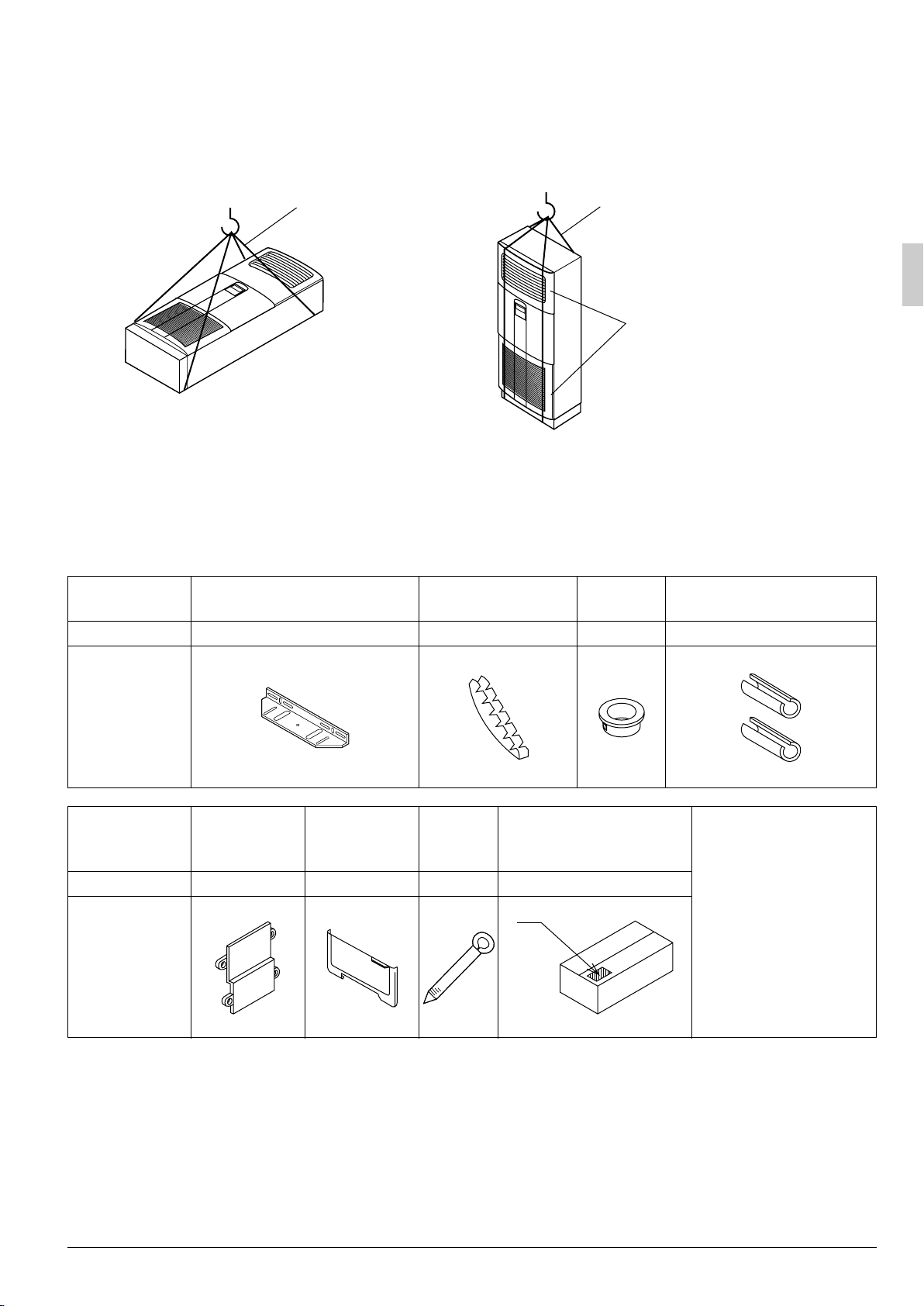
• When transporting by hanging the unit, use a sling of soft material as shown below.
(1) Horizontal hanging (2) Vertical hanging
Sling
*Be sure that the sling
does not slide in the
direction of the arrow.
• When moving the unit at or after opening, do not apply force to plastic parts.
• When selecting installation site, refer to the paper pattern (part of packaging material).
• For the installation of an outdoor unit, refer to the installation manual attached to the outdoor unit.
Sling
Apply cloth or corrugated
fibreboard so that the air
discharge grille and air inlet
grille are not damaged
1. ACCESSORIES
Check the following accessories are included with the unit.
Name Bracket for installation
Quantity 1 set 2 pcs. 1 pc. 1 each
(1)
Shape
(Attached to the top
Control
Name
Quantity 1 pc. 1 pc. 5 pcs. 1 pc.
Shape
panel patch
plate
(6) (7) (8) (9)
panel)
Remote
controller lid
Through hole
protecting rubber
(2) (3) (4) For gas pipe
Clamp Installation pattern
Bush Insulation for fitting
(5) For liquid pipe
(Other)
(10) Operation
manual
(11) Installation
manual
(12) Screws
(M5 × 12, 2 pcs.)
(Part of packing material)
2. OPTIONAL ACCESSARIES
• When the indoor unit is to be controlled by two remote controllers (refer to “FIELD SETTING”), install
them on an adequate place, referring to the related technical information.
(As for the installation procedure, follow the instruction in “Remote controller installation procedure”
attached to the remote controller.)
English 3
Page 6
FOR THE FOLLOWING ITEMS, TAKE SPECIAL CARE DURING CONSTRUCTION AND
CHECK AFTER INSTALLATION IS FINISHED.
1. Items to be checked after completion of work
Items to be checked If not properly done, what is likely to occur Check
Are the indoor and outdoor unit fixed
firmly?
Is the gas leak test finished? It may result in insufficient cooling.
Is the unit fully insulated? Condensate water may drip.
Does drainage flow smoothly? Condensate water may drip.
Does the power supply voltage
correspond to that shown on the name
plate?
Are wiring and piping correct?
Is the unit safely grounded? Dangerous at electric leakage.
Is wiring size according to specifications?
Is something blocking the air outlet or inlet
of either the indoor or outdoor units?
Are refrigerant piping length and
additional refrigerant charge noted down?
The unit may drop, vibrate or make noise.
The unit may malfunction or the components burn out.
The unit may malfunction or the components burn out.
The unit may malfunction or the components burn out.
It may result in insufficient cooling.
The refrigerant charge in the system is not clear.
2. Items to be checked at time of delivery *Also review the “SAFETY PRECAUTIONS”
Items to be checked Check
Did you explain about operations while showing the instruction manual to your customer?
Did you hand the instruction manual over to your customer?
Points for explanation about operations
The items with WARNING and CAUTION marks in the instruction manual are the items
pertaining to possibilities for bodily injury and material damage in addition to the general usage of
the product. Accordingly, it is necessary that you make a full explanation about the described
contents and also ask your customers to read the instruction manual.
3. NOTE TO THE INSTALLER
Be sure to instruct customers how to properly operate the unit (especially operating different functions,
and adjusting the temperature) by having them carry out operations themselves while looking at the
manual.
4 English
Page 7
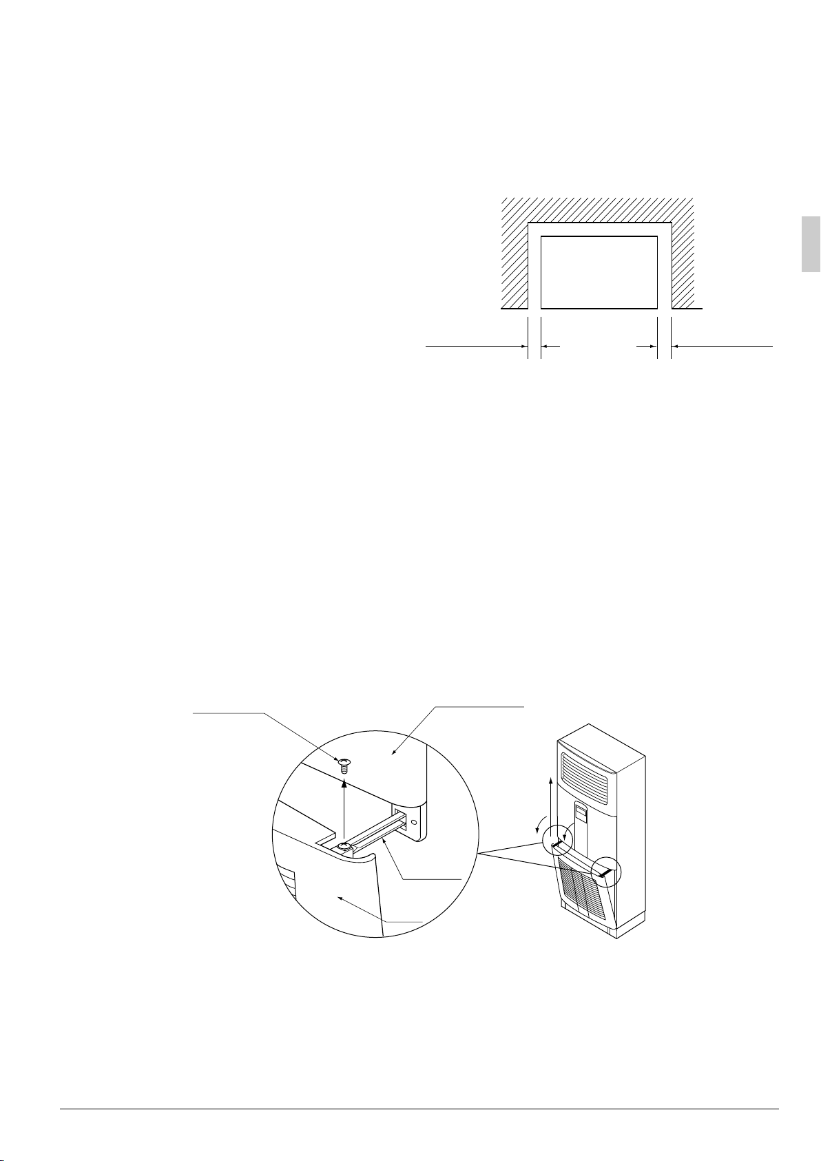
3. SELECTING INSTALLATION SITE
Select an installation site where the following conditions are satisfied after obtaining your customer’s
approval.
• Where optimum air distribution can be ensured.
• Where nothing blocks the air inlet and outlet, and
where sufficient clearance for maintenance and
service can be ensured.
• Where condensate can be properly drained.
• Where the floor is strong enough to bear the indoor
unit weight.
• Make sure that the floor is not remarkably tilted.
• Where there is no risk of flammable gas leakage.
• Where piping between indoor and outdoor units is
possible within the allowable limit. (Refer to the
installation manual for the outdoor unit.)
• Keep indoor unit, outdoor unit, power supply wiring
and transmission wiring at least 1 meter away from
televisions and radio receivers. This is to prevent
image interference and noise in those electrical
appliances.
(Noise may be generated depending on the
conditions under which the electric wave is generated, even if 1 meter is kept.)
50mm
or more
50mm
or more
4. INDOOR UNIT INSTALLATION
As for the parts to be used for installation work, be sure to use the provided accessories and specified parts
designated by our company.
〈Fixing procedure〉
• Fix the indoor unit by using embedded bolt, etc. to prevent falling down of the vertically-long shaped unit.
1. Detach the air intake grille.
Remove the screws (R & L, total 2) locking the grille stopper. Then, (1) lean the grille forward you, and
(2) lift upward and out.
M4 × 12
Screw
Air intake
grille
Front panel
(2)
(1)
Grille
stopper
English 5
Page 8
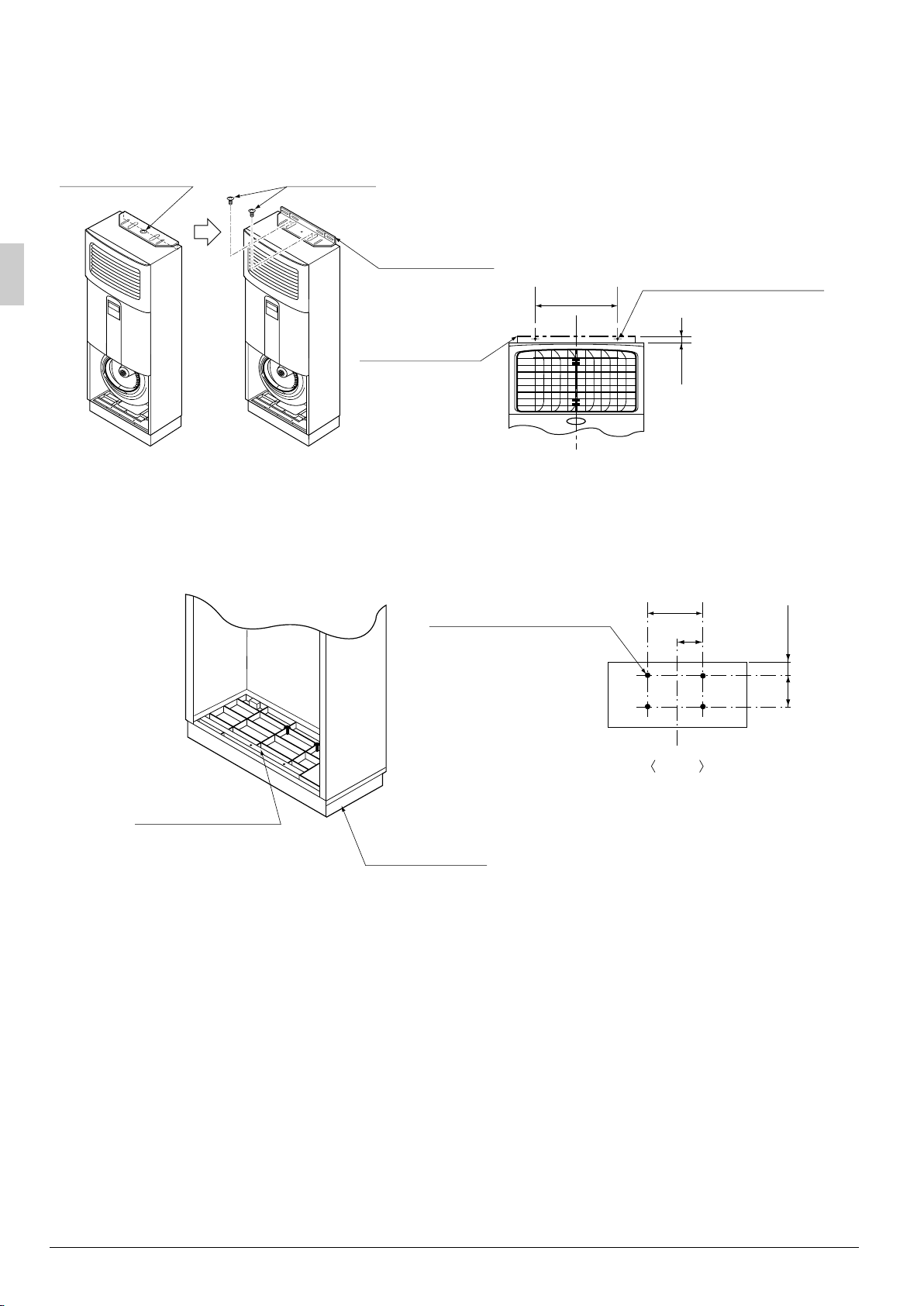
2. In case of normal installation site.
Loosen the fixed screw and remove the bracket for installation (1) tentatively attached to the top panel.
Fix the bracket with the attached screws (12) to the top panel as shown in the figure. Then fix the indoor
unit to the wall surface with wood screws (field supply).
Fixing screw
Screw (12)
Bracket for
installation (1)
(attached)
Bracket for
installation (1)
(attached)
330
2-7 × 15 slot
(For locking with
wood screw:
field supply)
18
3. In the case of earthquake endurance installation site.
Perform the fixing procedure above and also fix the bottom frame. Fix the indoor unit to the floor with
anchor bolts (to be locally procured) using fixing holes (×4) on the bottom frame.
• Use the locations indicated on the installation pattern (9) (part of packing material).
4 - φ14 hole, Depth: 30
(For locking with bolt)
260
130
57
(79)
144
(202)
Front
Fixing hole (× 4)
Bottom frame
• Dimensions in ( ) for 100 - 125 models
• Unit [mm]
5. REFRIGERANT PIPING WORK
〈For refrigerant piping of outdoor units, see the installation manual attached to the outdoor unit.〉
〈Execute heat insulation work completely on both sides of the gas piping and the liquid piping.
Otherwise, a water leakage can result sometimes.〉
(When using a heat pump, the temperature of the gas piping can reach up to approximately 120°C, so use
insulation which is sufficiently resistant.)
〈Also, in cases where the temperature and humidity of the refrigerant piping sections might exceed
30°C or RH80%, reinforce the refrigerant insulation. (20mm or thicker) Condensation may form on the
surface of the insulating material.〉
〈Before refrigerant piping work, check which type of refrigerant is used. Proper operation is not
possible if the types of refrigerant are not the same.〉
6 English
Page 9

CAUTION
• Use a pipe cutter and flare suitable for the type of refrigerant.
• Apply ester oil or ether oil around the flare section before connecting.
• To prevent dust, moisture or other foreign matter from infiltrating the tube, either pinch the end or
cover it with tape.
• Do not allow anything other than the designated refrigerant to get mixed into the refrigerant circuit,
such as air, etc. If any refrigerant gas leaks while working on the unit, ventilate the room thoroughly
right away.
• The outdoor unit is charged with refrigerant.
• Use copper alloy seamless pipes (ISO 1337).
• Be sure to use both a spanner and torque wrench together, as
shown in the drawing, when connecting or disconnecting pipes
to/from the unit. (Refer to Fig. 1)
• Refer to “Table 1” for the dimensions of flare nut spaces.
• When connecting the flare nut, coat the flare section (both
inside and outside) with ester oil or ether oil, rotate three or four
times first, then screw in. (Refer to Fig. 2)
NOTE
• Use the flare nut included with the unit main body.
CAUTION
Do not let oil get on the screw holders on the dressing board.
Oil can weaken the screw holders.
Ta b le 1
Pipe size Tightening torque Flare dimensions A (mm) Flare
φ9.5 (3/8”) 32.7 - 39.9 N·m 12.8 - 13.2
φ15.9 (5/8”) 61.8 - 75.4 N·m 19.3 - 19.7
Fig. 1
Torque wrench
Flare nut
Fig. 2
Ester oil or ether oil
Piping union
45˚Ⳳ2˚
A
90˚Ⳳ0.5˚
Spanner
R0.4-0.8
• Refer to “Table 1” to determine the proper tightening torque.
CAUTION
Overtightening may damage the flare and cause a refrigerant leakage.
Not recommendable but in case of emergency
You must use a torque wrench but if you are obliged to install the unit without a torque wrench, you may
follow the installation method mentioned below.
After the work is finished, make sure to check that there is no gas leak.
When you keep on tightening the flare nut with a spanner, there is a point where the tightening torque
suddenly increases. From that position, further tighten the flare nut the angle shown below:
Pipe size Further tightening angle Recommended arm length of tool
φ9.5 (3/8”) 60 to 90 degrees Approx. 200mm
φ15.9 (5/8”) 30 to 60 degrees Approx. 300mm
English 7
Page 10

1. How to rig refrigerant piping.
• Detach the pipe retainer.
〈 In the case of left or right piping 〉
1. Open the holes on the right (left) side panel. (Refer to Fig. 3)
2. Pass refrigerant pipes, drain pipes, and unit wiring through the hole on the side panel.
Fig. 3
Bottom frame
〈 In the case of rear piping 〉
1. Open the holes on the rear panel. (Refer to Fig. 5)
2. Pass refrigerant pipes, drain pipes, and unit wiring through the hole on the rear panel.
〈 In case of downward piping 〉
1. Cut holes in the indicated area of the bottom frame. (Refer to Fig. 5)
2. Pass refrigerant pipes, drain pipes, and unit wiring through the hole on the bottom frame.
Side panel
Through hole (Select either one)
(left and right side panels and rear panel)
∗ Attach the through hole protection (2) ( )
after making the opening.
Through hole for wiring (Select either one)
(left and right side panels)
∗ Attach the bush (3) ( ) after making the opening.
Fig. 4
Insulation for fitting (4)(5)
(attached)
Drain hose
inside the unit
Pipe retainer
Knock-out hole
Fig. 5
Cut holes here.
Fix using
the clamp (8)
Rear panel
Bottom frame
• After rigging pipes and wiring, lock down the refrigerant pipes, drain hose inside the unit, indooroutdoor unit transmission wiring and grounding line, in the piping guide. (For electrical wiring work,
see “ELECTRIC WIRING WORK”.)
8 English
Page 11

6. DRAIN PIPING WORK
1. Rig the drain piping.
Rig the drain line to ensure proper drainage. Also, observe the following to prevent leaks.
Drain hose
inside the unit
Fan housing
Liquid pipe
Gas pipe
CAUTION
• Bundle the drain pipe to the refrigerant pipes as shown at right or take other means to anchor it down, so
as not to apply pressure to the hose inside the unit. This is necessary to prevent the drain pipe from
disconnecting and to ensure proper insulation. Keep the drain pipe sloping at a minimum 1/100 gradient, to
prevent air pockets.
• The drain pipe may be clogged if water accumulates in the drain pipe.
• Condensate can form on the pipe and leak from the unit. Therefore, definitely insulate the pipe in at least
the below two places.
• All pipe in the room and inside the unit.
• At connection between the unit’s drain hose and building drain pipe.
Drain pipes (Procure in field.)
Vinyl tube (pipe size I.D. 20mm)
Bottom frame
Anchor hose here.
2. After rigging the drain hose, check that drainage flows smoothly and that water does
not leak from connections.
• Carefully pour approximately
1,000cc of water through the air
discharge outlet so that it falls
directly onto the heat
exchanger at an angle without
splashing. (See figure at right.)
* If water is poured too fast or if
water pressure is too high, the
water will pass through the
heat exchanger and drip on
the fan motor below it.
* If water gets on the inner front
wall, it will leak onto the floor.
Air discharge
outlet
Heat
exchanger
CAUTION
• In order to prevent the intrusion of small animals, seal the pipe penetration hole with putty or heat insulating
material (field supply).
• Drain piping connections
Do not connect the drain piping directly to sewage pipes that smell of ammonia. The ammonia in the
sewage might enter the indoor unit through the drain pipes and corrode the heat exchanger.
English 9
Page 12

7. SEPARATE INSTALLATION OF THE CONTROL PANEL
• For this unit, remote controller (operation part) attached to the control panel can be installed separately by
using the field supplied remote controller cord.
Refer to section of ELECTRIC WIRING WORK (p. 12) for specifications of remote controller cord.
1. Detach the terminal box lid and detach the remote controller cable from the remote
controller terminal board.
Remote controller wiring
Front plate
panel
Remote controller
Screw
(M4 × 2)
terminal board
Terminal box lid
2. Remove the remote controller
holding plate on the back side of
the front plate panel.
3. Fix the attached hole covering
plate on the front plate panel where
the remote controller was set.
Screw (M4)
Front plate panel
Remote
controller
Remote controller
holding plate
Screw (M4 × 4)
Front plate panel
Hole covering plate (6)
(attached)
Screw (M4 × 4)
10 English
Page 13

4. Connect the remote controller
wiring (field supplied) to the
Terminal box lid
Remote controller
terminal board
remote controller terminal board
and lead the wiring out of the unit
as shown below.
• Lock the remote controller wiring to the
piping guide.
Remote controller wiring
5. Open the remote controller and attach the remote controller wiring (field supplied).
(Remote controller wiring has no polarity)
1. Remove the upper part of the remote
controller.
Remove the upper part of the remote
controller with screw drivers, etc.
2. Attach the remote controller wiring.
3. Reassemble the remote controller in
the opposite order of 1. and at last,
install the attached remote controller
lid (7).
Upper part of
remote controller
Remote controller wiring
Remote
controller
PC board
Upper part of
remote controller
Upper part of
remote controller
Insert the latch on
the bottom first.
Remote controller
lid (7) (attached)
6. After the remote controller wiring, reassemble the indoor unit referring to procedures
1. ~ 4.
English 11
Page 14

8. ELECTRIC WIRING WORK
• All field supplied parts and materials and electric works must conform to local codes.
• Use copper wire only.
• For electric wiring work, refer also to “WIRING DIAGRAM” attached to the unit body.
• For remote controller wiring details, refer to the installation manual attached to the remote controller.
• All wiring must be performed by an authorized electrician.
• A circuit breaker capable of shutting down power supply to the entire system must be installed.
• Be sure to install an earth leakage breaker.
Failure to install an earth leakage breaker may result in electric shocks.
• Refer to the installation manual attached to the outdoor unit for the size of power supply electric wire
connected to the outdoor unit, the capacity of the circuit breaker and switch, and wiring instructions.
• Be sure to ground the air conditioner.
• Do not connect the ground wire to gas pipes, plumbing pipes, lightning rods, or telephone ground wires.
• Gas pipes: could explode and cause fires if there was a gas leak.
• Plumbing pipes: no grounding effect if hard vinyl pipes are used.
• Telephone ground wires or lightning rods: the ground potential could rise dangerously high if hit by
lightning.
• Specifications for field wire
Wiring the units
Remote controller cord
(In case of installing the
control panel separately)
Wire
H05VV-U4G
(NOTE 1)
Vinyl cord with sheath or
cable (2 wire) (NOTE 2)
2
Size (mm
)
2.5 –
0.75 - 1.25 Max. 500m
Length
NOTE
1. Shows only in case of protected pipes. Use H07RN-F in case of no protection.
2. Insulated thickness : 1mm or more.
How to connect wiring
Earth terminal
Earth terminal
Clamp
Power supply
321
terminal board (3P)
Wiring the units
Earth wire
Wiring
Pipe retainer
diagram
Terminal box lid
〈 Methods of wiring units and connecting remote controller cords 〉
• Detach the Terminal box lid as shown in the figure and connect the wires to the unit wiring terminal board
(3P) on the right side of the unit matching phase. Then, fix the wire using the clamp.
• Arrange the wires and fix a lid firmly so that the lid does not float during wiring work.
• Lock wires connecting the units and the grounding line to the pipe retainer.
[ PRECAUTIONS ]
• Do not clamp remote controller cords together with wires connecting the units. Doing so may cause
malfunction.
• Remote controller cords and wires connecting the units should be located at least 50mm from other electric
wires. Not following this guideline may result in malfunction due to electrical noise.
12 English
Page 15

• In order to prevent the intrusion of small creatures, seal the wiring outlet with putty or heat insulating
material (field supply). (If small creatures, such as insects, intrude into the unit, the creatures may cause
short-circuiting in the terminal box.)
CAUTION
• Observe the notes mentioned below when wiring to the power supply terminal board.
Precautions to be taken for power supply wiring
(Use a round crimp-style terminal for connection to the power supply terminal board. In case it cannot be
used due to unavoidable reasons, be sure to observe the following instructions.)
• Do not connect wires of different gauge to the same power supply terminal.
(Looseness in the connection may cause overheating.)
• When connecting wires of the same gauge, connect them according to the below figure.
• In wiring, make certain that prescribed wires are used, carry out complete connections, and fix the wires
so that outside forces are not applied to the terminals.
• Do not tighten the terminal screw excessively, or
otherwise the screw may be damaged.
• The tightening torque of each terminal screw is shown
in the table on the right-hand side.
Terminal block for remote controller wiring 0.79~0.97
Terminal block for wiring between units
Earth terminal
Tightening torque (N·m)
1.18~1.44
1.44~1.94
Do not connect wires
of different gauges.
(WRONG)
Round crimp-style
terminal
Connect wires of the
same gauge to both
side. (GOOD)
Do not connect wires
of the same gauge to
one side. (WRONG)
Electric wire
GOOD WRONG WRONG
9. WIRING EXAMPLE
(For the wiring of outdoor units, refer to the installation manual attached to the outdoor unit.)
Confirm the system type.
• Pair type: 1 control panel controls 1 indoor unit (standard system).
• 2 remote controller control: 1 control panel and 1 remote controller control 1 indoor unit.
• Group control: 1 control panel controls up to 16 indoor units (All indoor units operate according to the
control panel).
Pair type 2 remote controller control
Main power supply Main power supply
Main switch
Fuse
Main switch
Fuse
Outdoor unit
123
Outdoor unit
123
Indoor unit
Control
Panel
1
2
3
P1P2
P1P2
Control
Panel
1
2
3
P1P2
P1P2
(NOTE 2)
Indoor unitIndoor unit
English 13
Page 16

Group control
Main power supply Main power supply Main power supply
Main switch Main switch Main switch
FuseFuseFuse
Outdoor unitOutdoor unitOutdoor unit
123
Control
Panel
1
2
3
P1P2
P1P2
123
Control
Panel
1
2
3
P1P2
P1P2
123
Control
Panel
(NOTE 3)(NOTE 3)
1
2
3
P1P2
P1P2
Indoor unitIndoor unitIndoor unit
NOTE
1. All transmission wiring except for the remote controller wires must match the terminal symbol.
2. If the unit is under 2 remote controller control, perform additional wiring of the remote controller to the
remote controller terminal board. (Refer to the section entitled SEPARATE INSTALLATION OF THE
CONTROL PANEL)
3. If the unit is under group control, detach the remote controller cord connecting the remote controller
terminal board and the control panel. (Refer to the section entitled SEPARATE INSTALLATION OF THE
CONTROL PANEL)
Control by 2 Remote Controllers (controlling 1 indoor unit with 2 remote controllers)
• When using 2 remote controllers, one of either the control panel or the separate remote controller
must be set to “MAIN” and the other to “SUB”.
〈 MAIN/SUB CHANGEOVER 〉
1. Insert a screwdriver into the
Upper part of
remote controller
recess between the upper and
lower part of remote controller
and, working from the 2 positions,
pry off the upper part.
Lower part of
remote controller
Insert the screwdriver here and gentry work off
the upper part of remote controller.
14 English
Page 17

2. Turn the MAIN/SUB CHANGEOVER SWITCH on one of the two remote controller PC boards to “S”.
(Leave the switch to the other remote controller set to “M”.)
(Factory setting)
S
M
Remote controller
PC board
Only one remote controller
needs to be charged.
S
M
10. INSTALLATION OF AIR INTAKE GRILLE
1. Hook the air intake grille on the groove on the unit’s bottom frame in the order of (1) →
(2). (See below figure.)
(2)
(2)
(1)
Air intake
grille
(1)
Air intake grille
Bottom frame
Bottom frame
2. Fit the grille stopper (front panel) into the groove on the air intake grille and lock the
grille down in its original place by screw. (See below figure)
* Be careful not to overtighten screws.
M4 × 12
Screw
Front panel
Grille stopper
Air intake grille
Air intake grille
Bottom frame
English 15
Page 18

11. FIELD SETTING
Field setting
〈
Field setting must be made from the remote controller in accordance with the installation conditions.
• Setting can be made by changing the “Mode No.”, “FIRST CODE NO.”, and “
SECOND CODE NO
.”.
• Refer to the following procedure for Field setting.
〈 Procedure 〉
(1) Press the INSPECTION/TEST OPERATION button ( ) for 4 seconds or more in normal mode to
TEST
change to “FIELD SETTING MODE”.
(2) Press the TEMPERATURE SETTING button ( ) and choose the desired “Mode No.”.
(3) Under group control, if setting on each indoor unit is to be performed, press the TIMER MODE
START/STOP button ( ) and select the indoor unit number.
(Unnecessary in case of unified setting of group control)
(4) Press the PROGRAMING TIME upper part of the button ( ) and select the “FIRST CODE NO.”.
(5) Press the part of the button ( ) and select the “
SECOND CODE NO
.”.
(6) Press the TIMER ON/OFF button ( ) once to fix the change of the setting.
(7) Press the INSPECTION/TEST OPERATION button ( ) to return to the “NORMAL MODE”.
TEST
NOTE
• Setting is performed by a group as a seto when individual setting of each indoor unit is required, or when
the setting results must be checked, use the mode number is ( ).
UNIT NO.
Mode No.
〉
FIRST CODE NO.
UNIT NO.
SETTING
SECOND CODE NO.
(3)
TEST
(1)(7)
(4)
(6)
(5)
(2)
1. Setting air filter sign
• Control panels are equiped with the liquid crystal display of air filter signs to display the time to clean
air filters.
• Change the “
SECOND CODE NO
room.
(“
SECOND CODE NO.”
is factory set to “01” for filter contamination-light)
.” according to Table 2 depending on the amount of dirt or dust in the
16 English
Page 19

Ta b le 2
Setting
Air filter
contamination-light
Air filter
contamination-heavy
Filter cleaning period
(long life type)
Mode No.
Approx. 2500 hrs.
10 (20) 0
Approx. 1250 hrs. 02
FIRST
CODE NO.
CODE NO
2. Setting indoor unit number of simultaneous operation system
• When using in simultaneous operation system mode, change the SECOND CODE NO. as shown in
Table 3.
(SECOND CODE NO. is factory set to “01” for Pair system.)
Ta b le 3
Setting Mode No. FIRST CODE NO.
Pair system (1 unit)
Simultaneous operation
system (2-unit)
Simultaneous operation
system (3-unit)
11 (21) 0
SECOND CODE NO
01
02
03
SECOND
.
01
.
12. TEST OPERATION
Refer to the section of “FOR THE FOLLOWING ITEMS, TAKE SPECIAL CARE DURING
CONSTRUCTION AND CHECK AFTER INSTALLATION IS FINISHED” .
• After finishing the construction of refrigerant piping, drain piping, and electric wiring, conduct test operation
accordingly to protect the unit.
1. HOW TO TEST OPERATION
1 Open the gas side stop valve.
2 Open the liquid side stop valve.
Electrify crank case heater for 6 hours (Not required in case of a unit exclusively designed for cooling only).
3
Set to cooling operation with control panel and start operation by pushing ON/OFF button ( ).
4
5 Press INSPECTION/TEST OPERATION button ( ) 4 times (2 times for wireless remote controller)
and operate at Test Operation mode for 3 minutes.
6 Push AIR FLOW DIRECTION ADJUST button ( ) to make sure the unit is in operation.
7 Press INSPECTION/TEST OPERATION button ( ) and operate normally.
8 Confirm function of unit according to the operation manual.
PRECAUTIONS
• Refer to the diagnoses below if the unit does not operate properly.
• After completing the test run, press the INSPECTION/TEST OPERATION button once to put the unit
in inspection mode, and make sure the malfunction code is “00” (=normal).
If the code reads anything other than “00”, refer to the malfunction diagnoses below.
TEST
TEST
English 17
Page 20

2. HOW TO DIAGNOSE FOR PROBLEMS
With the power on. Troubles can be monitored on the
■ Trouble shooting with the display on the liquid crystal display
1 With the
When the operation stops due to trouble, operation lamp flashed, and “ ” and the error code are
indicated on the liquid crystal display . In such a case, diagnose the fault contents by referning to
the table on the Error code list it case of group control, the unit No. is displayed so that the indoor
unit no with the trouble can be recognized. (NOTE 2)
2 With the wireless remote controller.
(Refer also to the operation manual attached to the wireless remote controller)
When the operation stops due to trouble. the display on the indoor unit flashes. In such a case,
diagnose the fault contents with the table on the Error code list looking for the error code which can
be found by following procedures. (NOTE 2)
(1) Press the INSPECTION /TEST OPERATION button, “ ” is displayed and “ 0 ” flashes.
(2) Press the PROGRAMMING TIME button and find the unit No. which stopped due to trouble.
Number of beeps 3 short beeps...............Perform all the following operations
(3) Press the OPERATION MODE SELECTOR button and upper figure of the error code flashes.
(4) Continue pressing the PROGRAMMING TIME button unit it makes 2 short beeps and find the upper
code.
(5) Press the OPERATION MODE SELECTOR button and lower figure of the error code flashes.
Continue pressing the PROGRAMMING TIME button unit it makes a long beep and find the lower code.
(6)
• A long beep indicate the error code.
NOTE
1. Press the INSPECTION /TEST OPERATION button on control panel, “ ” starts flashing.
2. Keep down the ON/OFF button for 5 seconds or longer in the inspection mode and the above trouble
history disappears, after the trouble code goes on and off twice, followed by the code “00”(normal).
The display changes from the inspection mode to the normal mode.
control panel
. (NOTE 1)
1 short beep ................Perform (3) and (6)
1 long beep..................No trouble
control panel
control panel
.
.
3. Malfunction code
• For places where the error code is left blank, the “ ” indication is not displayed. Though the system
continues operating, be sure to inspect the system and make repairs as necessary.
• Depending on the type of indoor or outdoor unit, the malfunction code may or may not be displayed.
Code Malfunction/Remarks
A1 Indoor unit’s PC board faulty
A3 Drain water level abnormal
A6 Indoor fan motor overloaded, overcurrent or locked
A7 Swing flap motor locked
AF
AH
AJ
C4 Sensor for heat exchanger lamp is fault
C9 Sensor for suction air lamp is fault
CC
CJ
E0 Action of safety device (outdoor unit)
E1 Outdoor unit’s PC board faulty (outdoor unit)
E3 High pressure abnormal (outdoor unit)
E4 Low pressure abnormal (outdoor unit)
Humidifier faulty
Air cleaner faulty
Only the air cleaner does not function.
Type set improper
Capacity data is wrongly preset. Or there is nothing programmed in the data hold IC.
Temperature sensor system faulty
Sensor for remote controller is fault
The remote controller thermistor does not function, but the system thermo run is possible.
18 English
Page 21

E5 Compressor motor lock malfunction (outdoor unit)
E7
E9 Electronic expansion valve faulty (outdoor unit)
F3 Discharge pipe temperature abnormal (outdoor unit)
H3 High pressure switch faulty (outdoor unit)
H7 Outdoor motor position signal malfunction (outdoor unit)
H9
J2
J3
J5 Suction pipe thermistor faulty (outdoor unit)
J6
J9 Suction temperature sensor faulty (outdoor unit)
JA Pressure sensor for discharge pipe faulty (outdoor unit)
JC Pressure sensor for suction pipe faulty (outdoor unit)
L4
L5
L8
L9
LC Transmission malfunction between the outdoor control units’ inverters (outdoor unit)
P1 Open-phase (outdoor unit)
P3 PC board temperature sensor malfunction (outdoor unit)
P4 Heat-radiating fin temperature sensor malfunction (outdoor unit)
PJ
U0
U1
U2
U4
UF
U5
Outdoor fan motor lock malfunction
Outdoor fan instantaneous overcurrent malfunction (outdoor unit)
Outdoor air thermistor faulty (outdoor unit)
The air conditioner comes to a stop due to an error depending on the model or operating
conditions.
Current sensor faulty
Discharge pipe thermistor faulty (outdoor unit)
The air conditioner comes to a stop due to an error depending on the model or operating
conditions.
Heat exchanger thermistor faulty (outdoor unit)
The air conditioner comes to a stop due to an error depending on the model or operating
conditions.
Overheated heat-radiating fin (outdoor unit)
Inverter cooling defect.
Instantaneous overcurrent (outdoor unit)
Possible earth fault or short circuit in the compressor motor.
Electric thermal (outdoor unit)
Possible electrical overload in the compressor or cut line in the compressor motor.
Stall prevention (outdoor unit)
Compressor possibly locked.
Type set improper (outdoor unit)
Capacity data is wrongly preset. Or there is nothing programmed in the data hold IC.
Suction pipe temperature abnormal
The quantity of refrigerant may be insufficient.
Reverse phase
Reverse two of the L1,L2 and L3 leads.
Power source voltage malfunction (outdoor unit)
Inverter phase loss or a failure in the main circuit capacitor may be resulting.
Transmission error (indoor unit – outdoor unit)
Wrong wiring between indoor and outdoor units or malfunction of the PC board mounted
on the indoor and the outdoor units.
If UF is shown, the wiring between the indoor and outdoor units is not properly wired.
Therefore, immediately disconnect the power supply and correct the wiring. (The
compressor and the fan mounted on the outdoor unit may start operation independent of
the remote controller operation.)
Transmission error (indoor unit – remote controller)
Transmission is improper between the indoor unit and the remote controller.
English 19
Page 22

U8
UA
UC
UJ Transmission failure in accessory equipment
Malfunction in transmission between main and sub remote controllers.
(Malfunction in sub remote controller.)
Miss setting for multi system
Error in multi-system settings for simultaneous ON/OFF operation.
Central control address overlapping
13. WIRING DIAGRAM
(Refer to Fig. 6)
1 TO OUTDOOR UNIT 2
3 TERMINAL BOX 4 INDOOR UNIT
5NOTE) 7
CONTROL PANEL
20 English
Page 23

WIRING DIAGRAM
2
3
FVQ71 · 100 · 125BV1B3D058900-1
4
CONNECTOR
(ADAPTOR FOR WIRING)
CONNECTOR FOR OPTIONAL PARTS
X33A
INDOOR UNIT
CAPACITOR
C1
A1P PRINTED CIRCUIT BOARD
(INTERFACE
CONNECTOR
CONNECTOR
ADAPTOR FOR SKY AIR SERIES)
(POWER SUPPLY FOR ADAPTOR)
X35A
X60A
X61A
LIGHT EMITTING DIODE
(SERVICE MONITOR GREEN)
MAGNETIC RELAY (M1F)
MAGNETIC RELAY (M1S)
MOTOR (INDOOR FAN)M1F
MOTOR (SWING FLAP)M1S
HAP
KAR
K1R-K4R
1
TEMPERATURE SWITCHQ1M
THERMISTOR (AIR)
THERMISTOR (COIL)
R1T
R2T
5
TRANSFORMER
(220-240V/22V)
SELECTOR SWITCH (EMERGENCY)
LIMIT SWITCH (SWING FLAP)S1Q
SS1
T1R
TERMINAL STRIP
X1M
NOTES)
CONTROL PANEL
SIGNAL TRANSMISSION
SIGNAL RECEIVER CIRCUIT
(REMOTE CONTROLLER)
TC
RC
SELECTOR SWITCH (MAIN/SUB)
CIRCUIT
SS1
: SHORT CIRCUIT CONNECTOR : FIELD WIRING
THE ATTACHED INSTALLATION MANUAL.
ENGINEERING DATA AND CATALOGS, ETC. BEFORE CONNECTING.
ENGINEERING DATA, ETC.
BRN: BROWN BLU: BLUE
1. : TERMINAL , : CONNECTOR
2. IN CASE USING CENTRAL REMOTE CONTROLLER, CONNECT IT TO THE UNIT IN ACCORDANCE WITH
3. X33A, X35A, X60A, X61A ARE CONNECTED WHEN THE OPTIONAL ACCESSORIES ARE BEING USED.
4. REMOTE CONTROLLER MODEL VARIES ACCORDING TO THE COMBINATION SYSTEM, CONFIRM
5. CONFIRM THE METHOD OF SETTING THE SELECTOR SWITCH (SS1) BY INSTALLATION MANUAL AND
THERMISTOR (AIR)R1T
USE H07RN-F IN CASE OF NO PROTECTION.
6. SYMBOLS SHOWS AS FOLLOWS: RED: RED BLK:BLACK WHT: WHITE ORG:ORANGE
7. SHOWS ONLY IN CASE OF PROTECTED PIPES.
Fig. 6
English 21
Page 24

3PA60136-8Y EM07A043A
(0802) HT
 Loading...