

Daikin FTK-J, FTXN-J Technical Manual
TECHNICAL MANUAL
Inverter Single Split
Series Air Conditioner
FTK-J, FTXN-J Series
— Cooling only & Heatpump [50Hz] —
TM-5WMY-J-ST-A2
R410A

Table of Contents
i
Table of Contents
Nomenclature......................................................................................................................1
Indoor ............................................................................................................................1
Outdoor ..........................................................................................................................1
Product Line-Up .............................................................................................................2
Application Information .....................................................................................................4
Operating Range ...........................................................................................................4
Refrigerant Circuit Diagrams .........................................................................................5
Installation Guideline .....................................................................................................6
Sound Data ........................................................................................................................10
Sound Pressure Level ................................................................................................10
NC Curve ..................................................................................................................... 11
Engineering & Physical Data ...........................................................................................13
Performance Data .............................................................................................................15
Calculation Steps .........................................................................................................15
Performance Tables .....................................................................................................17
Outline & Dimension ........................................................................................................25
Wiring Diagram .................................................................................................................28
Service & Maintenance ....................................................................................................32
Troubleshooting ...............................................................................................................34

Nomenclature
1
Nomenclature
Indoor
FT 25 J X V1 9 K
Power Supply
V1: 220-240V 1 phase 50 Hz
Factory Origin
X: Malaysia
Product Series
J: J Series
Capacity
25: 2500 Watt*
System
K: Inverter Cooling Only
XN: Inverter Heat Pump
Outdoor
R 25 F X V1 9K
Power Supply
V1: 220-240V / 1 Phase / 50 Hz
Factory Origin
X: Malaysia
Product Series
F: F Series
C: C Series
Capacity
25: 2500 Watt*
System
K: Inverter Cooling Only
XN: Inverter Heat Pump
Revision
“ - “ : Original Copy
9 : First Revision
Revision
“ - “ : Original Copy
9 : First Revision
Remark:
* : Capacity value under Nomenclature is an indication.
Please refer to Engineering and Physical Data for exact capacity value.
Model
FT: Wall Mounted
Model
R: Single Split Condensing Unit
Nomenclature
2
Product Line-Up
Indoor Unit
FTK, FTXN
Nomenclature
Classifi cation
Handset
PCB
Air Purifi cation
BRC52A62
BRC52A61
W_2_03C
W_2_04A
Saranet Filter
Titanium Apatite Filter
COOLING
FTK25JXV19 X X X X
FTK35JXV19 X X X X
FTK50JXV19 X X X X
FTK60JXV19 X X X X
HEATPUMP
FTXN25JXV1 X X X X
FTXN35JXV1 X X X X
FTXN50JXV1 X X X X
FTXN60JXV1 X X X X
Nomenclature
3
Outdoor Unit
RK, RXN
Nomenclature
Refrigerant Control
PCB
Fin
Compressor
Others
Cap Tube
EXV
Main PCB (ADGPA31)
Main PCB (2P273854)
Filter PCB (3P273862)
Hydrophilic (Blue)
Hydrophilic (Gold)
Bare Aluminium
Swing
Drain Elbow
COOLING
RK25FXV19 X X X X
RK35FXV19 X X X X
RK50CXV19 X X X X X
RK60CXV19 X X X X X
HEATPUMP
RXN25FXV1 X X X X X
RXN35FXV1 X X X X X
RXN50CXV1 X X X X X X
RXN60CXV1 X X X X X X
4
Application Information
Application Information
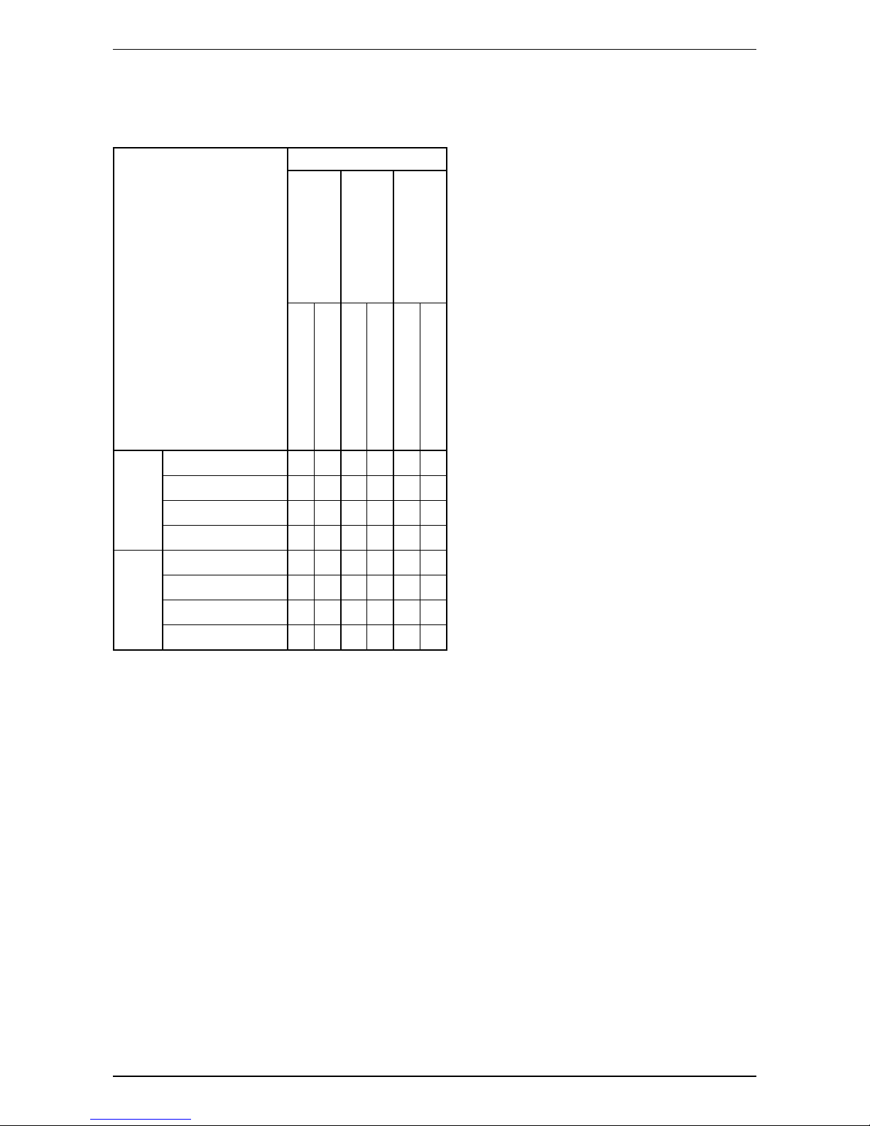
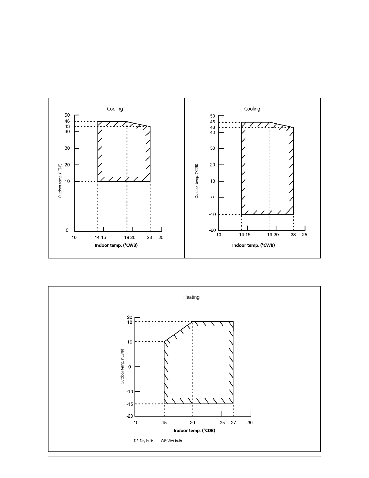
Operating Range
Ensure the operating temperature is in allowable range.
Cooling
FTK25/35JXV19 – RK25/35FXV19
FTXN25/35JXV1 – RXN25/35FXV1
FTK50/60JXV19 – RK50/60CXV19
FTXN50/60JXV1 – RXN50/60CXV1
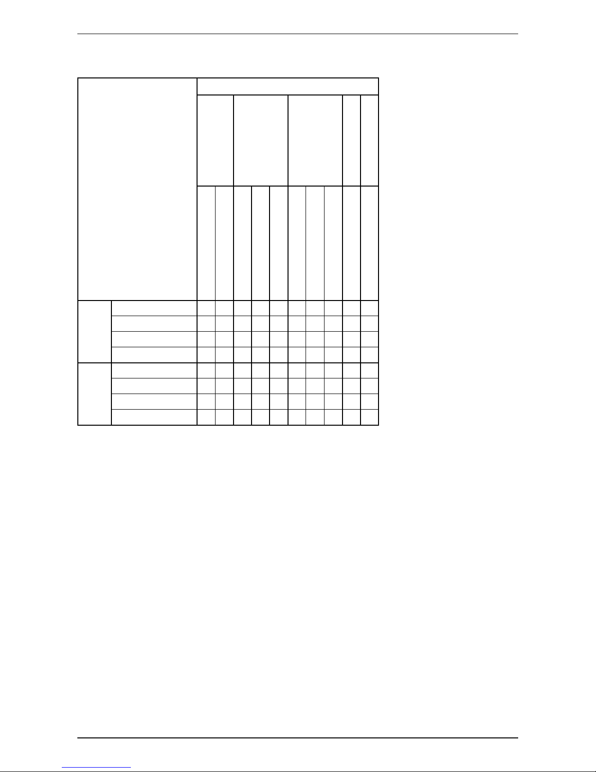
Heating
FTXN25/35/50/60JXV1 – RXN25/35FXV1;50/60CXV1
5
Application Information
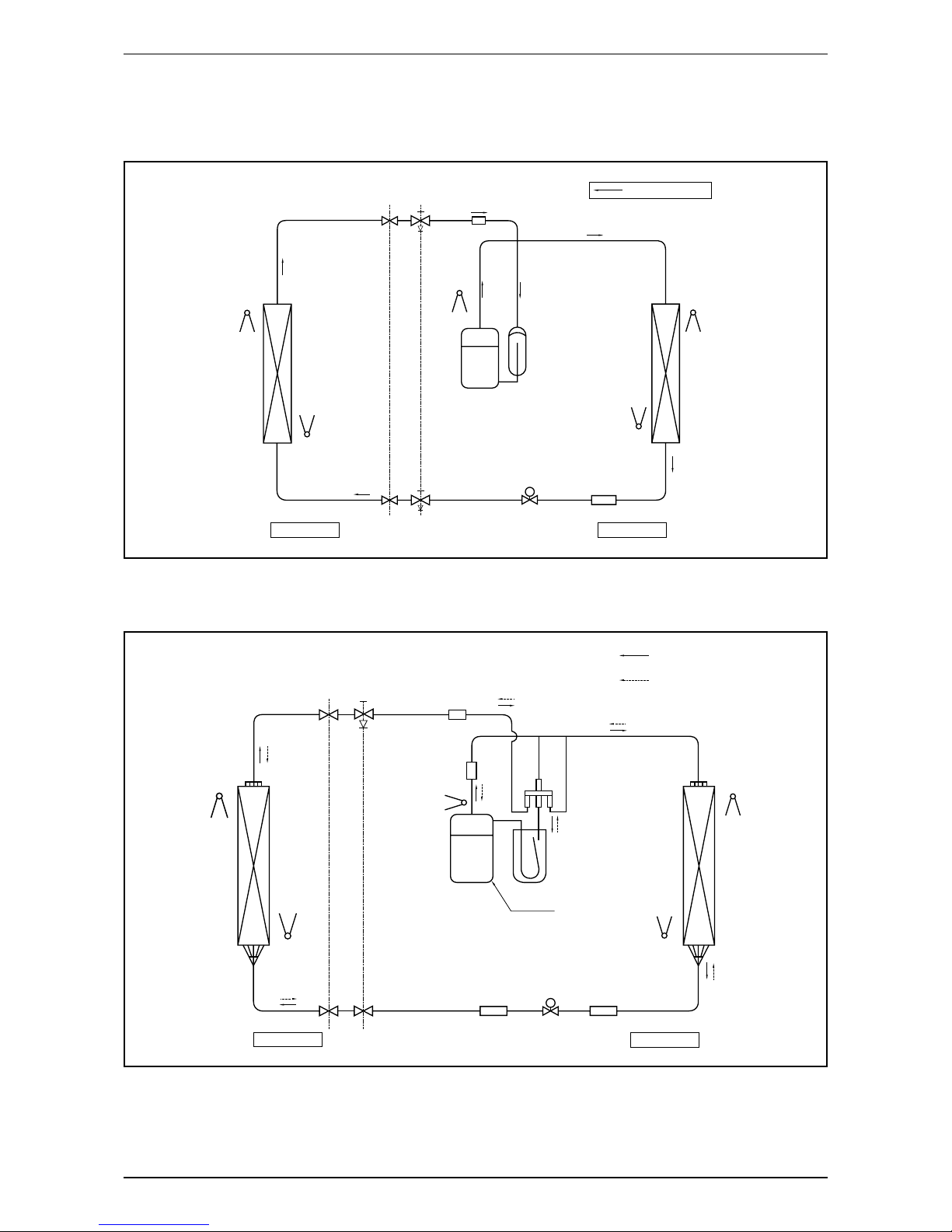
Refrigerant Circuit Diagrams
Model: FTK25JXV19 – RK25FXV19 / FTK35JXV19 – RK35FXV19 / FTK50JXV19 – RK50CXV19 /
FTK60JXV19 – RK60CXV19
PIPING
GAS
3 WAY
VALV E
MUFFLER
COOLING OPERATION
PIPING
LIQUID
RETURN AIR SENSOR
HEAT EXCHANGER
(INDOOR UNIT)
PIPE TEMPERATURE SENSOR
DISCHARGE
ACCUMULATOR
COMPRESSOR
STRAINER
OUTDOOR UNIT
INDOOR UNIT
3 WAY
VALV E
ELECTRONIC EXPANSION
VALV E
PIPE TEMPERATURE SENSOR
RETURN AIR SENSOR
HEAT EXCHANGER
(OUTDOOR UNIT)
Model: FTXN25JXV1 – RXN25FXV1 / FTXN35JXV1 – RXN35FXV1 / FTXN50JXV1 – RXN50CXV1 /
FTXN60JXV1 – RXN60CXV1
3 WAY VALVE
MUFFLER
MUFFLER
4 WAY VALVE
Cooling operation
Heating operation
PIPING
LIQUID
ELECTRONIC EXPANSION
VALV E
RETURN AIR SENSOR
HEAT EXCHANGER
(OUTDOOR UNIT)
PIPE TEMPERATURE SENSOR
DISCHARGE PIPE
SENSOR
PIPE TEMPERATURE SENSOR
RETURN AIR SENSOR
HEAT EXCHANGER
(OUTDOOR UNIT)
COMPRESSOR
ACCUMULATOR
STRAINER
STRAINER
OUTDOOR UNIT
INDOOR UNIT
2 WAY VALVE
PIPING
GAS

6
Application Information
Installation Guideline
Sharp edges and coil surfaces are potential injury hazard. Avoid from contact with them.
Installation Diagram
Front panel
50mm or more from walls
(on both sides)
Indoor unit
Air filter
M4 x 12L
30mm or more from ceiling
Caulk pipe hole
gap with putty.
Cut thermal insulation pipe
to an appropriate length and
wrap it with tape, making
sure that no gap is left in the
insulation pipe’s cut line.
Wrap the insulation pipe with the
finishing tape from bottom to top.
Outdoor Unit
Opening service lid
Service lid is opening/closing
type.
Opening method
1) Remove the service lid
screws.
2) Pull out the service lid
diagonally down in the
direction of the arrow.
3) Pull down.
Service lid
7
Application Information
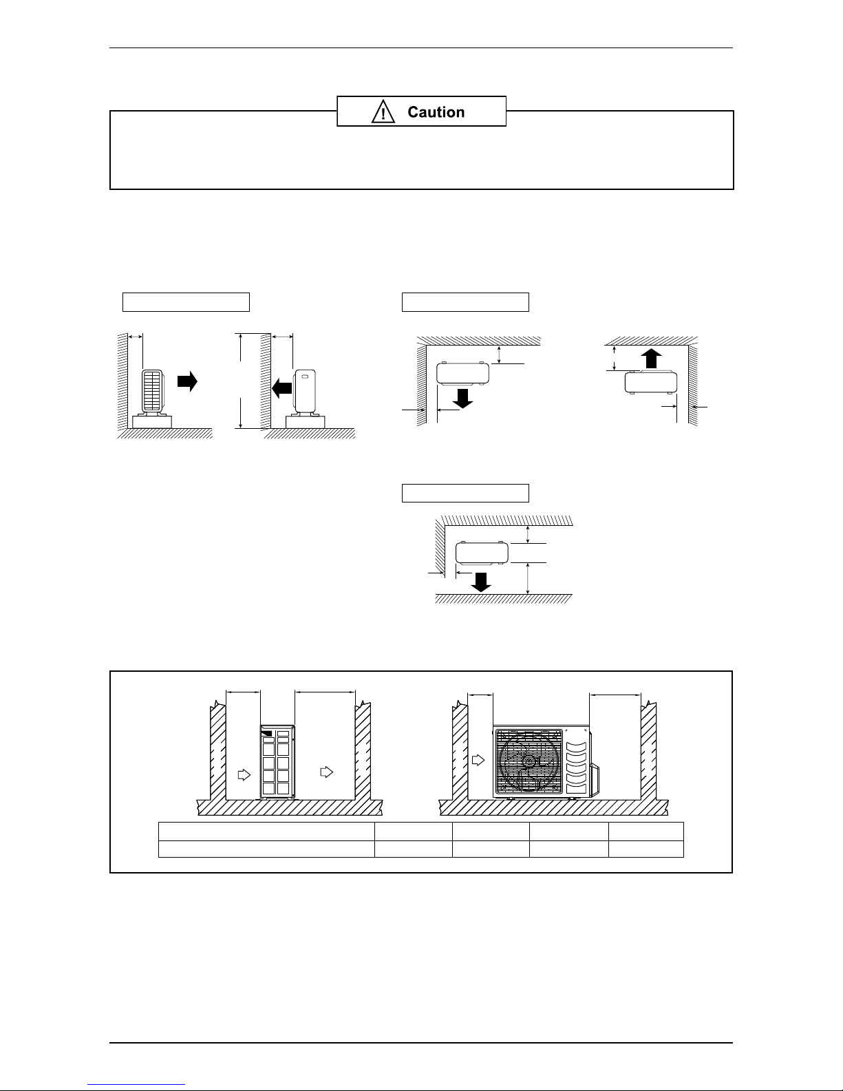
Outdoor Clearance
If the condensing unit is operated in an atmosphere containing oils (including machine
oils), salt (coastal area), sulphide gas (near hot spring, oil refi nery plant), such as
substances may lead to failure of the unit.
• Where a wall or order obstacle is in the path of outdoor unit’s intake or exhaust airfl ow, follow the
installation guidelines below.
• For any of the below installation patterns, the wall height on the exhaust side should be 1200mm or less.
Model: RK25/35FXV19, RXN25/35FXV1
Wall facing one side Wall facing two side
More than 50
Side View Top View
Top View
Unit : mm
More than 50
More than 150
More than 50
More than 300
More than 50
More than 100
More
than 100
1200 or
less
More than 150
Wall facing three side
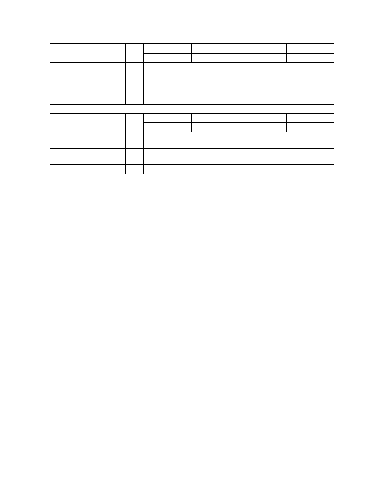
Model: RK50/60CXV19, RXN50/60CXV1
A
AIR INLET
AIR DISCHARGE
B
OBSTACLE
OBSTACLE
C
AIR INLET
SERVICE SPACE
D
OBSTACLE
OBSTACLE
ALL MODELS
Minimum Distance
A
300 mm
B
1000 mm
C
300 mm
D
500 mm
8
Application Information
Cable Size
Model Unit
FTK25JXV19 FTK35JXV19 FTK50JXV19 FTK60JXV19
RK25FXV19 RK35FXV19 RK50CXV19 RK60CXV19
Power supply cable size
Number of wire
mm
2
1.5
3
2.5
3
Interconnection cable size
Number of wire
mm
2
1.5
4
2.5
4
Recommended fuse A 16 20
Model Unit
FTXN25JXV1 FTXN35JXV1 FTXN50JXV1 FTXN60JXV1
RXN25CXV19 RXN35CXV19 RXN50CXV19 RXN60CXV19
Power supply cable size
Number of wire
mm
2
1.5
3
2.5
3
Interconnection cable size
Number of wire
mm
2
1.5
4
2.5
4
Recommended fuse A 16 20
9
Application Information
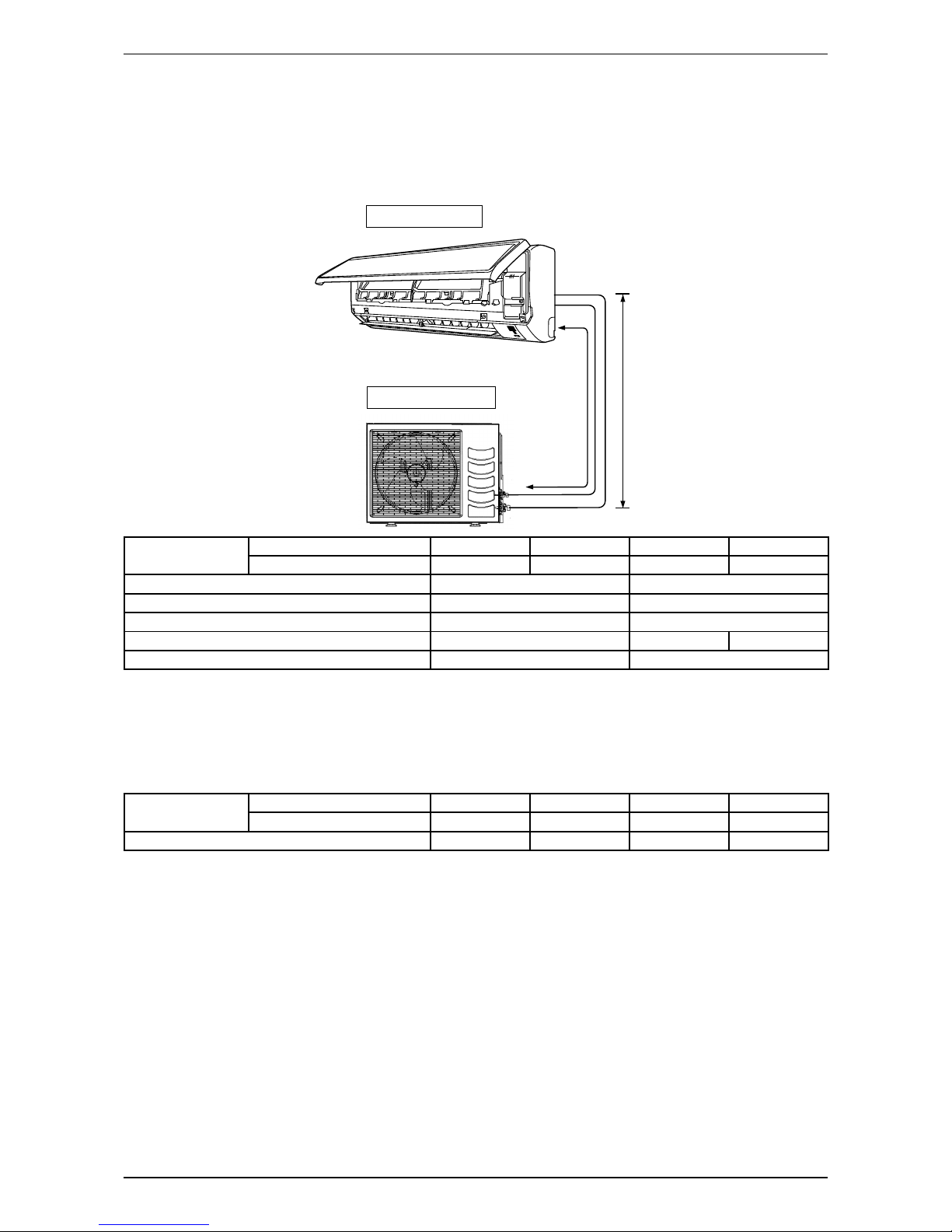
Refrigerant Piping
Piping Length and Elevation
When the pipe length becomes too long, both the capacity and reliability drop. As the number of bends increases,
system piping resistance to the refrigerant fl ow increases, thus lowering the cooling capacity, and as the result
the compressor may become defective. Always choose the shortest path and follow the recommendation as
tabulated below:
Outdoor Unit
Indoor Unit
LE
Model
Indoor (FTXN/FTK) 25 35 50 60
Outdoor (RXN/RK) 25 35 50 60
Min. Allowable Length (L), m 3 3
Max. Allowable Length (L), m 20 30
Max. Allowable Elevation (E), m 10 10
Gas Pipe Size, mm/(in) 9.52 (3/8") 12.70 (1/2") 15.88 (5/8")
Liquid Pipe Size, mm/(in) 6.35 (1/4") 6.35 (1/4")
Additional Charge
• The refrigerant gas is charged in the outdoor unit and, if the piping length is 7.5m, additional charge of the
refrigerant after vacuuming is not necessary.
• When the piping length is more than 7.5m, additional refrigerant charge (g) per additional 1m length as
tabulated:
Model
Indoor (FTXN/FTK) 25 35 50 60
Outdoor (RXN/RK) 25 35 50 60
Additional charge [g/m] 20 20 20 20
Example:
FTXN25 & RXN25 with 12m piping length, additional piping length is 4.5m.
Thus, Additional charge = 4.5[m] x 20[g/m]
= 90.0[g]
10
Sound Data
Sound Data
Sound Pressure Level
Model Speed
1/1 Octave A-weighted Sound Pressure Level
(dB, ref 20μPa)
Overall
(dBA)
Noise
Criteria
125Hz 250Hz 500Hz 1kHz 2kHz 4kHz 8kHz
FTK25JXV19
FTXN25JXV1
Turbo 43 39 37 37 33 26 13 41 36
Hi 42 38 37 36 32 24 12 40 35
Me 37 33 32 30 25 17 13 34 29
Lo 32 29 28 24 19 14 13 29 22
Quiet 21 22 20 15 10 7 8 21 -
FTK35JXV19
FTXN35JXV1
Turbo 41 39 38 38 36 29 15 42 37
Hi 40 38 38 37 34 27 14 41 36
Me 36 32 32 30 26 18 11 34 29
Lo 33 29 29 25 21 15 11 30 23
Quiet 24 22 21 17 11 7 7 22 -
FTK50JXV19
FTXN50JXV1
Turbo 39 41 40 40 37 29 16 44 39
Hi 35 37 37 36 32 25 12 40 35
Me 34 36 36 34 29 22 11 38 33
Lo 30 34 33 31 26 18 10 35 30
Quiet 28 32 30 28 22 14 10 32 26
FTK60JXV19
FTXN60JXV1
Turbo 42 44 43 42 40 35 20 46 41
Hi 39 41 40 38 36 31 16 43 37
Me 37 39 38 37 33 28 13 41 36
Lo 33 36 35 33 28 22 11 37 32
Quiet 28 33 32 28 23 17 9 33 26
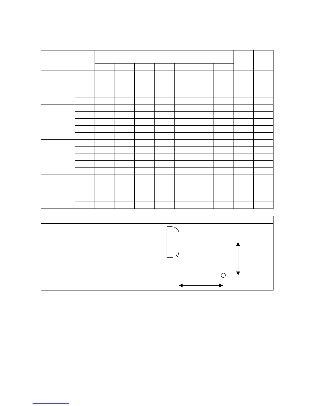
Model Measuring Location
FTK25JXV19
FTK35JXV19
FTK50JXV19
FTK60JXV19
FTXN25JXV1
FTXN35JXV1
FTXN50JXV1
FTXN60JXV1
Microphone
1.0m
0.8m
Standard : JIS C 9612

11
Sound Data
NC Curve
0
10
20
30
40
50
60
70
80
125 250 500 1000 2000 4000 8000
Sound pressure level (dB, ref 20μPa)
Octave-band frequency (Hz)
FTK25JXV19 / FTXN25JXV1
NC-20
NC-30
NC-25
NC-35
NC-40
NC-45
NC-50
NC-55
NC-60
NC-65
H
M
L
0
10
20
30
40
50
60
70
80
125 250 500 1000 2000 4000 8000
Octave-band frequency (Hz)
FTK35JXV19 / FTXN35JXV1
NC-20
NC-30
NC-25
NC-35
NC-40
NC-45
NC-50
NC-55
NC-60
NC-65
H
M
L
Sound pressure level (dB, ref 20μPa)
 Loading...