

Daikin FTXS20KVMA, FTKS12HV2S, FTKS20KVMA, FTXS46KVMA, FTKS25KVMA Service Manual
...
REMOVAL
PROCEDURE
SERVICE MANUAL
Indoor Unit
Inverter/Hybrid
Wall Mounted Type
2.0/2.5/3.5/4.6 kW Class
9000/12000 Btu/h Class
Si041137

Service Manual
Removal Procedure
Indoor Unit
Applicable Models
zCooling Only zHeat Pump
FTKS09HV2S FTXS20KVMA
FTKS12HV2S FTXS25KVMA
FTXS35KVMA
FTKS20KVMA FTXS46KVMA
FTKS25KVMA
FTKS35KVMA FTYN25KV1A
FTYN35KV1A
FTN25KV1A FTYN35KAV1A
FTN35KV1A
FTN35KAV1A FTXF125KC-W
FTXF125KC-R
FTKS20LVMA FTXF135KC-W
FTKS25LVMA FTXF135KC-R
FTKS35LVMA
FTKS46LVMA FTXS09LVJU
FTXS12LVJU
FTXS20LVMA
FTXS25LVMA
FTXS35LVMA
FTXS46LVMA

Si041137
Removal Procedure 1
Table of Contents
1. Removal of Air Filters..............................................................................2
2. Removal of Front Panel ..........................................................................4
3. Removal of Front Grille ...........................................................................5
4. Removal of Horizontal Blades / Vertical Blades......................................7
5. Removal of Electrical Box .....................................................................11
6. Removal of PCBs (Pattern 1)................................................................14
7. Removal of PCBs (Pattern 2)................................................................20
8. Removal of Swing Motors (Pattern 1) ...................................................24
9. Removal of Swing Motors (Pattern 2) ...................................................28
10.Removal of Indoor Heat Exchanger......................................................31
11.Removal of Fan Motor...........................................................................34
Note:
The illustrations may be slightly different depending on the model.

Removal of Air Filters Si041137
2 Removal Procedure
1. Removal of Air Filters
Procedure Warning Be sure to wait for 10 minutes or more after turning off all power
supplies before disassembling work.
Step
Procedure Points
1. Appearance features
Warning
Dangerous: High voltage
A high voltage is applied to all
the electric circuits of this
product including
thermistors.
When the signal receiver
catches a signal from the
remote controller, the
receiving tone sounds and
the operation lamp blinks
immediately to confirm the
signal reception.
When the [ON/OFF] button
is kept pressed for 5
seconds, the forced cooling
operation is performed for
about 15 minutes.
2. Remove the air filters.
1
Open the front panel to
the position where it
stops.
2
Slightly push up the
center knob of the air
filter and release the
hooks.
The air filter is not marked
for difference between the
right and left sides.
The air filter can be set
easily by inserting it along
the guides.
Insert the air filter with the
"FRONT" mark faced up.
Be sure to insert the hooks
(at 2 lower positions) when
reassembling the air filter.
3
Pull out the air filter
downward and remove
it.
(R7900)
(R7901)
Signal receiver
Operation lamp
TIMER lamp
[ON/OFF] button Room temperature thermistor
INTELLIGENT
EYE sensor
INTELLIGENT
EYE lamp
(R7902)
Front panel
(R7903)
Air filter
Si041137 Removal of Air Filters
Removal Procedure 3
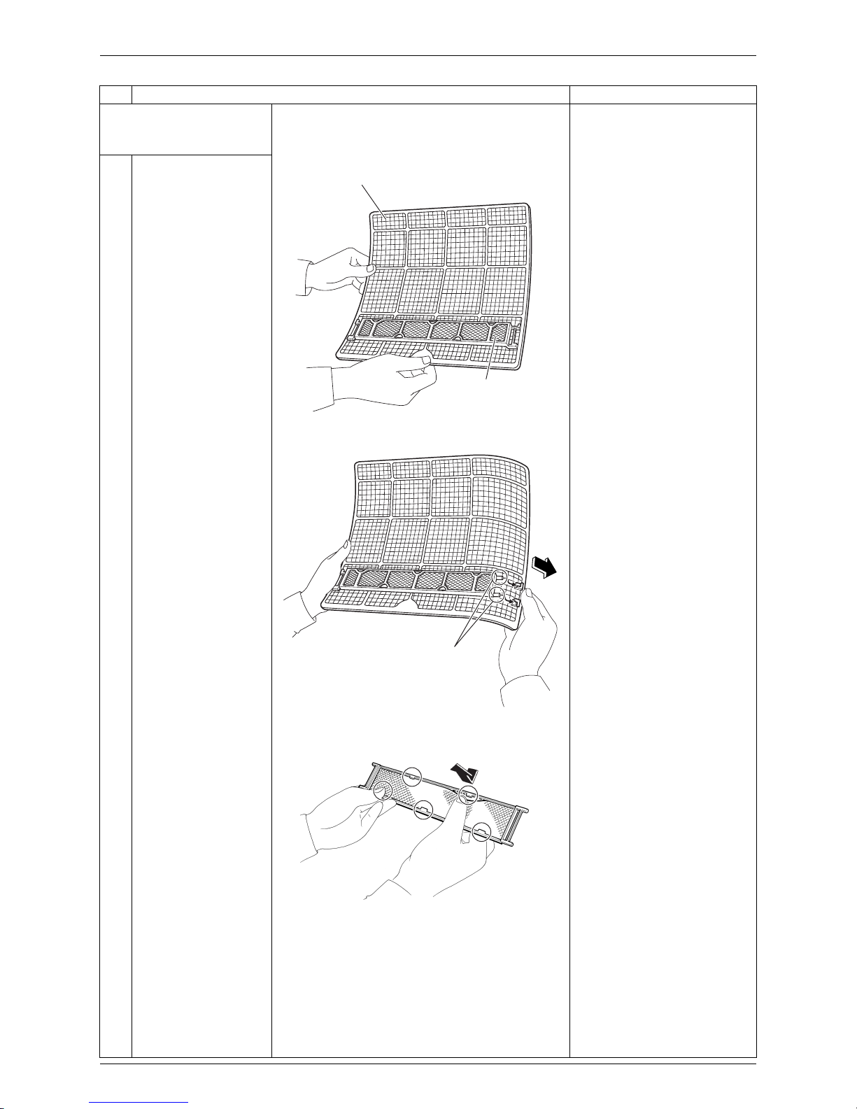
3. Remove the Titanium
apatite photocatalytic airpurifying filters.
1
The Titanium apatite
photocatalytic airpurifying filter ASSY is
attached to the back of
the air filter.
The right and left filters are
interchangeable.
2
Remove the Titanium
apatite photocatalytic
air-purifying filter ASSY
by unfastening the
projections from the
back of the air filter
frame.
3
Unfasten the 5 hooks
and remove the
Titanium apatite
photocatalytic airpurifying filter from its
frame.
Step
Procedure Points
(R7904)
Air filter
Titanium apatite
photocatalytic
air-purifying filter ASSY
(R13487)
Projection
(R13174)
Removal of Front Panel Si041137
4 Removal Procedure
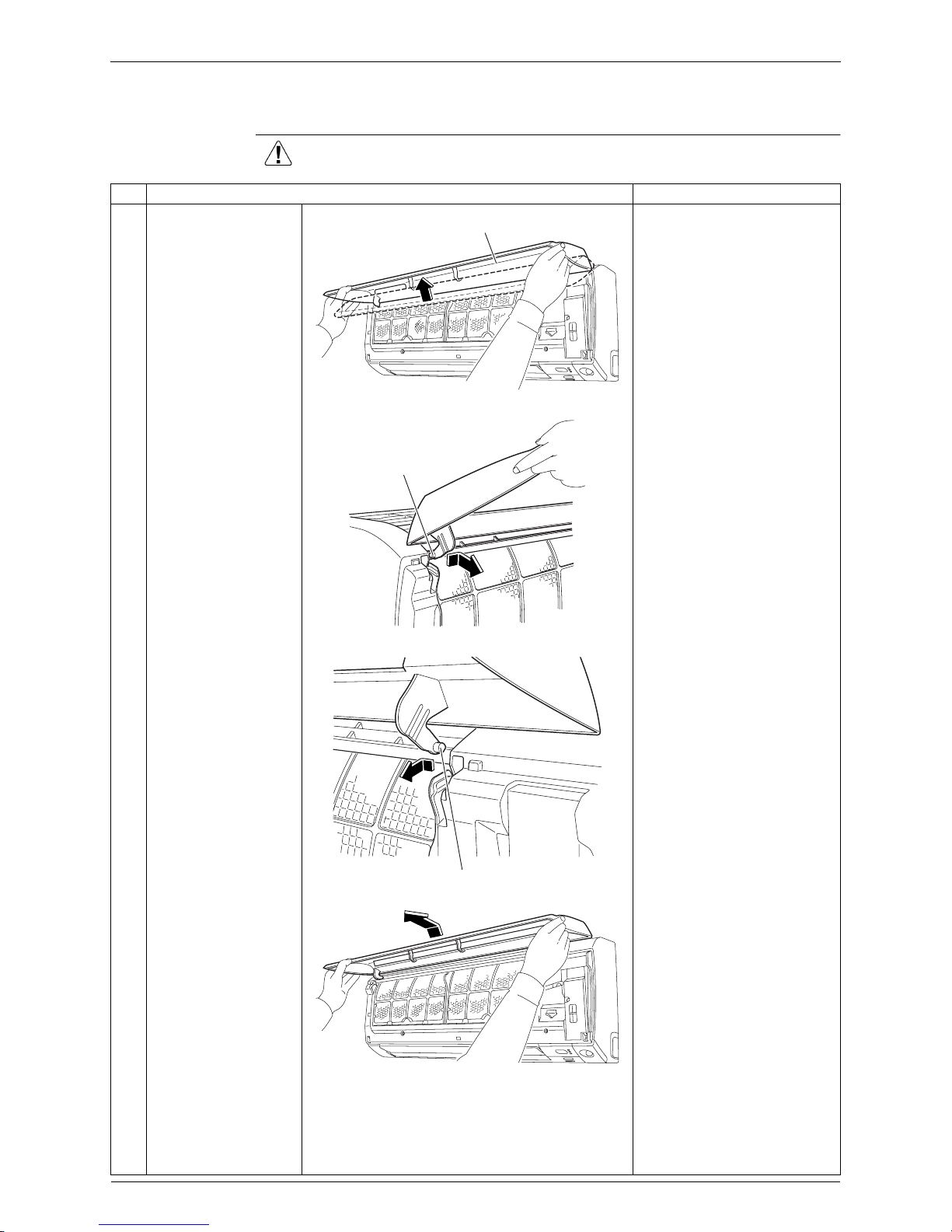
2. Removal of Front Panel
Procedure Warning Be sure to wait for 10 minutes or more after turning off all power
supplies before disassembling work.
Step
Procedure Points
1
Open the front panel
over the position where
it stops.
2
Slide the left rotary
shaft to the right and
release it.
When reassembling the front
panel, fit the right and left
rotary shafts one by one into
the grooves and fully push
them into position.
3
Slide the right rotary
shaft to the left and
release it.
4
Remove the front
panel.
(R7906)
Front panel
(R7907)
Rotary shaft
(R7909)
Rotary shaft
(R7910)
Si041137 Removal of Front Grille
Removal Procedure 5
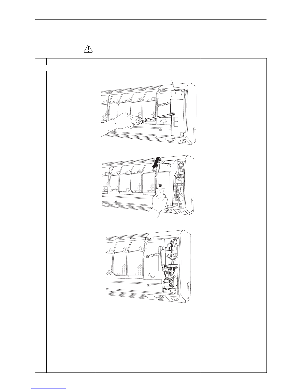
3. Removal of Front Grille
Procedure Warning Be sure to wait for 10 minutes or more after turning off all power
supplies before disassembling work.
Step
Procedure Points
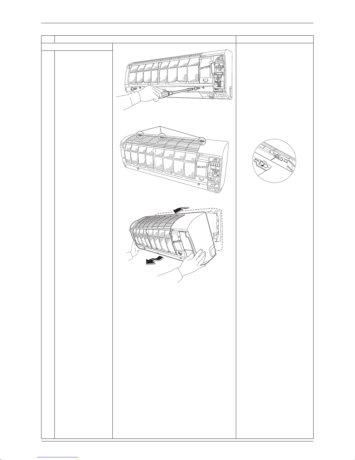
1. Remove the service cover.
1
Remove the screw of
the service cover.
Preparation
Remove the front panel
according to the “Removal of
Front Panel”.
2
Pull out the service
cover diagonally down
in the direction of the
arrow.
3
The figure shows the
inside.
(R7911)
Service cover
(R13488)
(R13489)
Removal of Front Grille Si041137
6 Removal Procedure
2. Remove the front grille.
1
Remove the 2 screws.
2
Unfasten the 3 hooks at
the top.
The convex marks (...) on
the front panel indicate the
position of the hooks.
3
Pull the upper part of
the front grille out and
lift the lower part up,
and then remove the
front grille.
When reassembling, make
sure that all the 3 hooks are
fastened as they were.
Step
Procedure Points
(R13490)
(R13491)
Hook
(R12715)
(R12268)

Si041137 Removal of Horizontal Blades / Vertical Blades
Removal Procedure 7
4. Removal of Horizontal Blades / Vertical Blades
Procedure Warning Be sure to wait for 10 minutes or more after turning off all power
supplies before disassembling work.
Step
Procedure Points
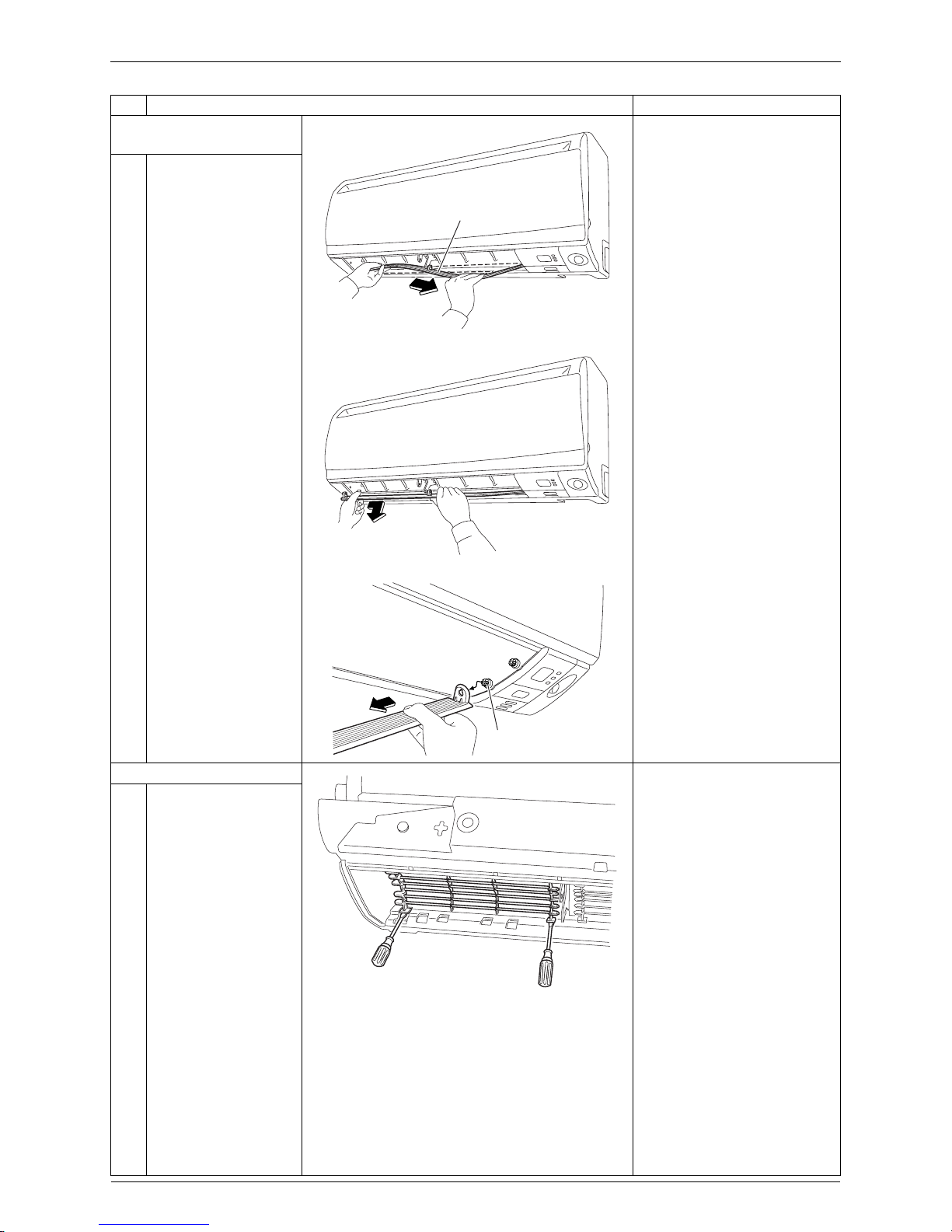
1. Remove the horizontal
blade (large).
1
Open the horizontal
blade (large).
When reassembling, mount
the large horizontal blade to
the upper position and the
small horizontal blade to the
lower position.
Do not put them in the wrong
place.
2
Unfasten the center
shaft while bending the
horizontal blade (large)
slightly.
3
Unfasten the left shaft.
4
Unfasten the right shaft.
There is a key alignment at
the right shaft. When
reassembling, insert the right
shaft first while turning.
After inserting the right shaft,
first mount the horizontal
blade to the center shaft and
then to the left shaft.
(R7921)
Horizontal blade (large)
Horizontal blade (small)
(R13175)
(R13073)
(R13492)
Key alignment
Removal of Horizontal Blades / Vertical Blades Si041137
8 Removal Procedure
2. Remove the horizontal
blade (small).
1
Unfasten the center
shaft while bending the
horizontal blade (small)
slightly.
2
Unfasten the left shaft.
3
Unfasten the right shaft.
There is a key alignment at
the right shaft. When
reassembling, insert the right
shaft first while turning.
After inserting the right shaft,
first mount the horizontal
blade to the center shaft,
and then to the left shaft.
3. Remove the fan guard.
Some models have no fan
guard.
1
Unfasten the hooks at
the lower part of the fan
guard with a flat
screwdriver.
Step
Procedure Points
(R13493)
Horizontal blade (small)
(R13494)
(R13495)
Key alignment
(R13751)
Si041137 Removal of Horizontal Blades / Vertical Blades
Removal Procedure 9
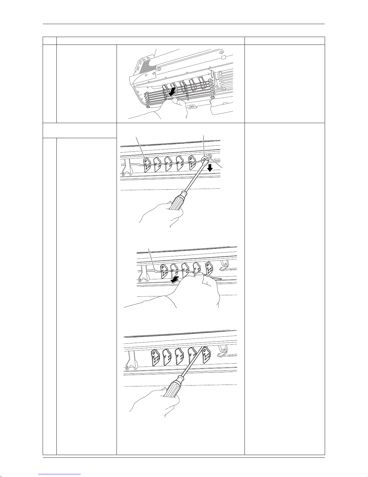
2
Remove the fan guard.
4. Remove the vertical blade
ASSYs.
1
Detach the pivot from
the interlock shaft for
vertical blades with a
flat screwdriver.
2
Remove the interlock
rod.
3
Unfasten the hooks at
the upper 3 positions by
pressing them with a
flat screwdriver.
Step
Procedure Points
(R8079)
(R13092)
Vertical blade ASSY
Pivot
Interlock
shaft
(R13093)
Interlock rod
(R13094)
Removal of Horizontal Blades / Vertical Blades Si041137
10 Removal Procedure
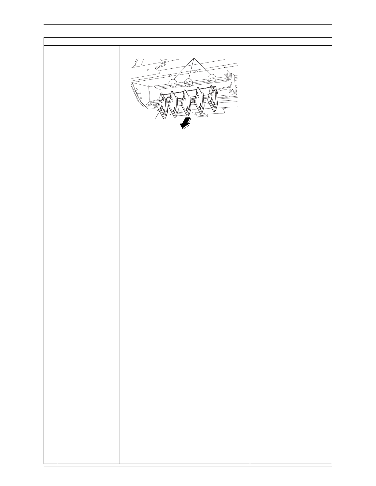
4
Remove the vertical
blade ASSY.
A vertical blade ASSY has 5
fins.
It is impossible to replace
only one fin.
The vertical blade ASSY is
not marked for difference
between right and left.
Step
Procedure Points
(R13095)
Hook
Vertical blade
 Loading...