

Daikin FTE60KV19, FTX60GV1B, FTE50KV19, FTM15NV2S, FTXD60FVMV Service Manual
...
REMOVAL
PROCEDURE
SERVICE MANUAL
Indoor Unit
Inverter / Non-Inverter
Wall Mounted Type
5.0/6.0/7.1 kW Class
15000/18000 Btu/h Class
Si041254EE

Service Manual
Removal Procedure
Indoor Unit
zCooling Only zHeat Pump
ATM18MV2S FTX50GV1B
FTX60GV1B
FTE50KV19 FTX71GV1B
FTE60KV19
FTXD50FVMV
FTM15NV2S FTXD60FVMV
FTM18NV2S FTXD71FVMV
FTM50JV14 FTXD50HVMV
FTXD60HVMV
FTM50KV1V FTXD71HVMV
FTN50JV1G FTXS50FVMV
FTN50JV1G9 FTXS60FVMV
FTXS71FVMV
FTNE50LV1
FTNE60LV1 FTXS50GVMV
FTNE50MV1 FTXS60GVMV
FTNE60MV1 FTXS71GVMV
FTNE50MV14
FTNE60MV14 FTXS50KVM
FTNE50MV18 FTXS60KVM
FTNE60MV18 FTXS71KVM
FTNE50MV1V
FTNE60MV1V
FTKS50FVM
FTKS60FVM
FTKS71FVM
FTKS50FVMV
FTKS60FVMV
FTKS71FVMV
FTKS50KVM
FTKS60KVM
FTKS71KVM

Si041254EE
Removal Procedure 1
Table of Contents
1. Air Filters .................................................................................................2
2. Front Panel..............................................................................................3
3. Front Grille ..............................................................................................4
4. Horizontal Blades....................................................................................5
5. Vertical Blade ASSYs..............................................................................6
6. Electrical Box ..........................................................................................8
7. PCBs .....................................................................................................10
8. Swing Motors ........................................................................................12
9. Indoor Heat Exchanger .........................................................................13
10.Fan Motor / Fan Rotor...........................................................................15
Note:
The illustrations may be slightly different depending on the model.
Air Filters Si041254EE
2 Removal Procedure
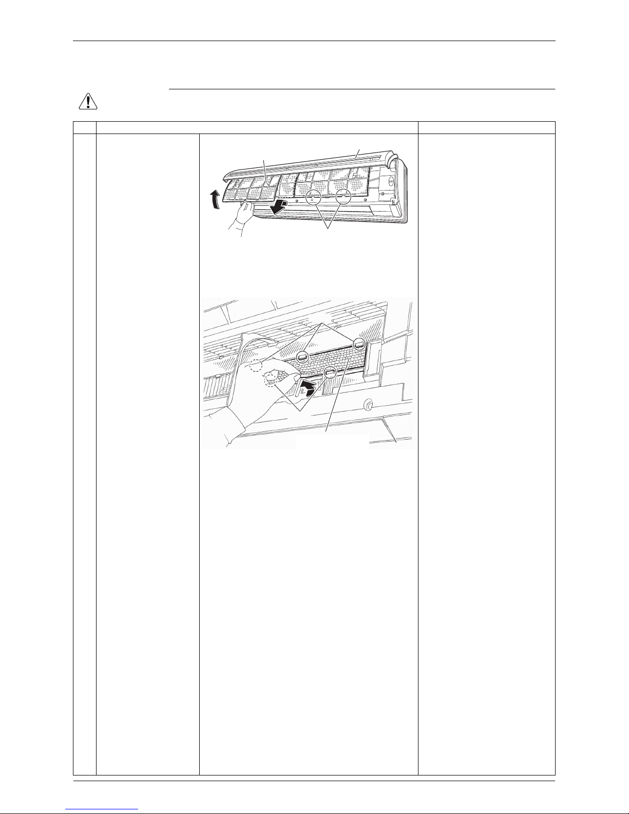
1. Air Filters
Warning
Be sure to wait for 10 minutes or more after turning off all power supplies before
disassembling work.
Step Procedure Points
1
2
3
Open the front panel.
Release each air filter
from the 2 hooks of the
front panel.
Remove the air filter by
pulling out downward.
The air filter is not marked
for difference between the
right and left sides.
Insert the air filter with the
“FRONT” mark faced up.
When reassembling, insert
the air filter along the guides.
Be sure to fasten the hooks
when installing the air filter.
4 Remove the Titanium
apatite photocatalytic
air-purifying filter, if
available, from the 5
hooks.
The right and left filters are
interchangeable.
Some models have no
Titanium apatite
photocatalytic air-purifying
filter.
Air filter
Hook
(R21150)
Front panel
Hook
Hook
(R23427)
Titanium apatite
photocatalytic
air-purifying filter
Si041254EE Front Panel
Removal Procedure 3
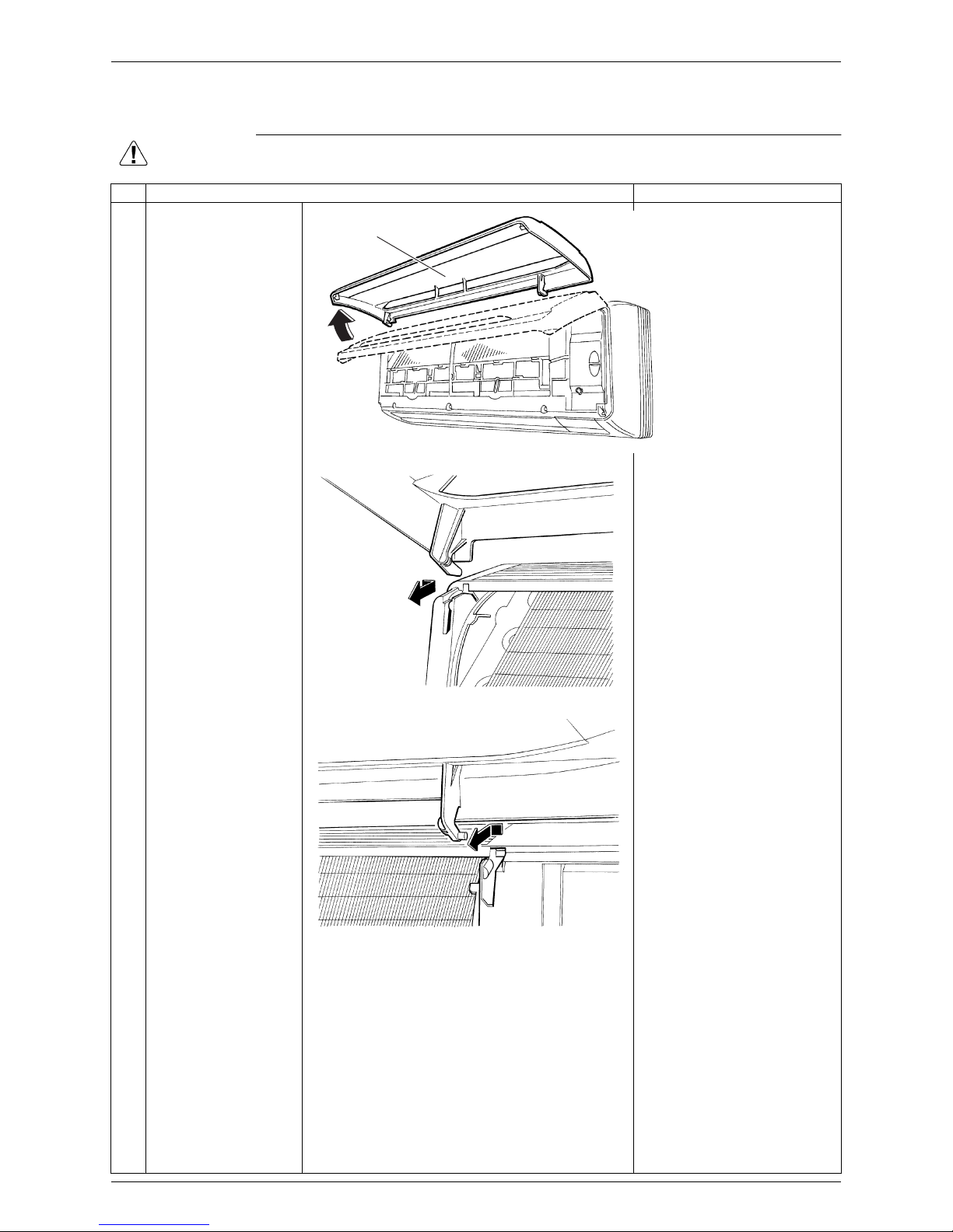
2. Front Panel
Warning
Be sure to wait for 10 minutes or more after turning off all power supplies before
disassembling work.
Step Procedure Points
1 Open the front panel
over the position where
it stops.
2 Slide the front panel to
the right and release
the left shaft.
When reassembling the front
panel, fit the right and left
shafts one by one into the
grooves and fully push them
into position.
34Release the right shaft
in the same way.
Remove the front panel.
(R23428)
Front panel
(R2754)
(R2755)
Front Grille Si041254EE
4 Removal Procedure
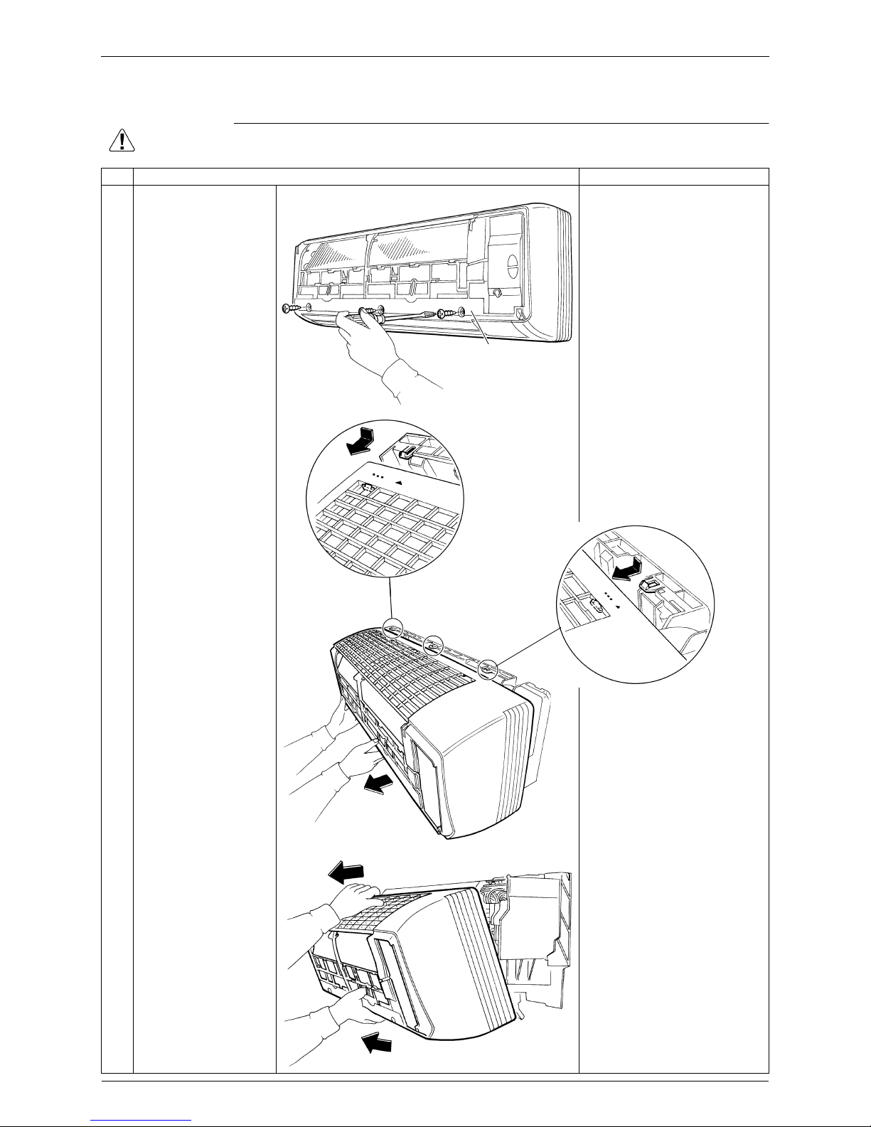
3. Front Grille
Warning
Be sure to wait for 10 minutes or more after turning off all power supplies before
disassembling work.
Step Procedure Points
1 Remove the 3 screws
of the front grille.
2 Unfasten the 3 hooks
on the top of the front
grille.
The convex marks (...) on
the front grille indicate the
position of the hooks.
When reassembling, make
sure that the 3 hooks are
securely fastened.
3 Pull the upper part of
the front grille out and
lift the lower part up,
and then remove the
front grille.
(R2758)
Front grille
(R17741)
(R15467)
 Loading...