How it Works
Log In / Sign Up
Buy Points
How it Works
FAQ
Contact Us
Questions and Suggestions
Users
Daikin
Loading...
F
FTXA20AB2V1BT
117
FTXA20B2V1BB
118
FTXA20B2V1BS
118
FTXA20B2V1BT
118
FTXA252V1BS
117
FTXA252V1BT
117
FTXA25A2V1BS
182
FTXA25A2V1BT
182
FTXA25A2V1BW
182
FTXA25AB2V1BS
117
FTXA25AB2V1BT
117
FTXA25B2V1BB
118
FTXA25B2V1BS
118
FTXA25B2V1BT
118
FTXA352V1BS
117
FTXA352V1BT
117
FTXA35A2V1BS
182
FTXA35A2V1BT
182
FTXA35A2V1BW
182
FTXA35AB2V1BS
117
FTXA35AB2V1BT
117
FTXA35B2V1BB
118
FTXA35B2V1BS
118
FTXA35B2V1BT
118
FTXA422V1BS
117
FTXA422V1BT
117
FTXA42A2V1BS
182
FTXA42A2V1BT
182
FTXA42A2V1BW
182
FTXA42AB2V1BS
117
FTXA42AB2V1BT
117
FTXA42B2V1BB
118
FTXA42B2V1BS
118
FTXA42B2V1BT
118
FTXA502V1BS
117
FTXA502V1BT
117
FTXA50A2V1BS
182
FTXA50A2V1BT
182
FTXA50A2V1BW
182
FTXA50AB2V1BS
117
FTXA50AB2V1BT
117
FTXA50B2V1BB
118
FTXA50B2V1BS
118
FTXA50B2V1BT
118
FTXB09AXVJURXB09AXVJU
4
FTXB12AXVJURXB12AXVJU
4
FTXB18AXVJURXB18AXVJU
4
FTXB20C2V1B
75
FTXB24AXVJURXB24AXVJU
4
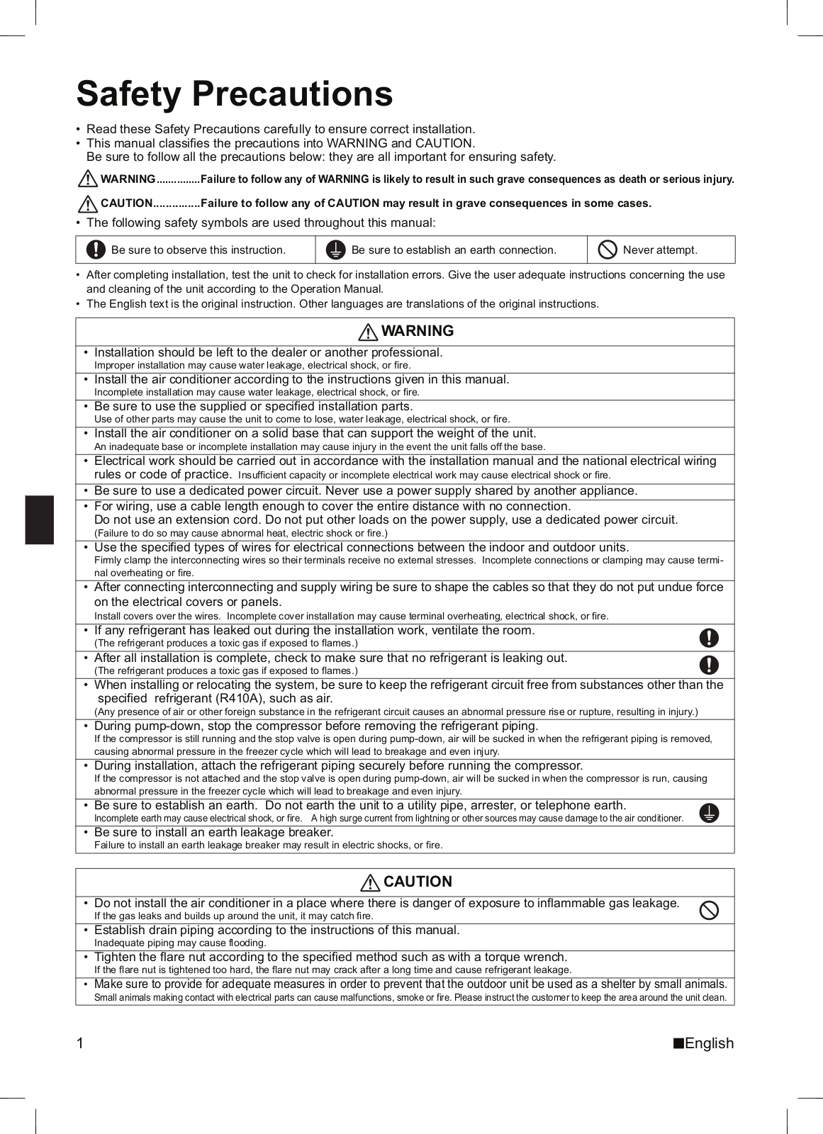
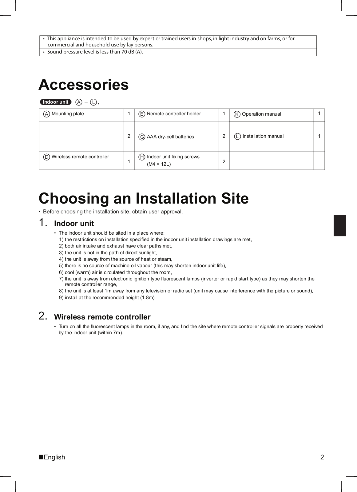
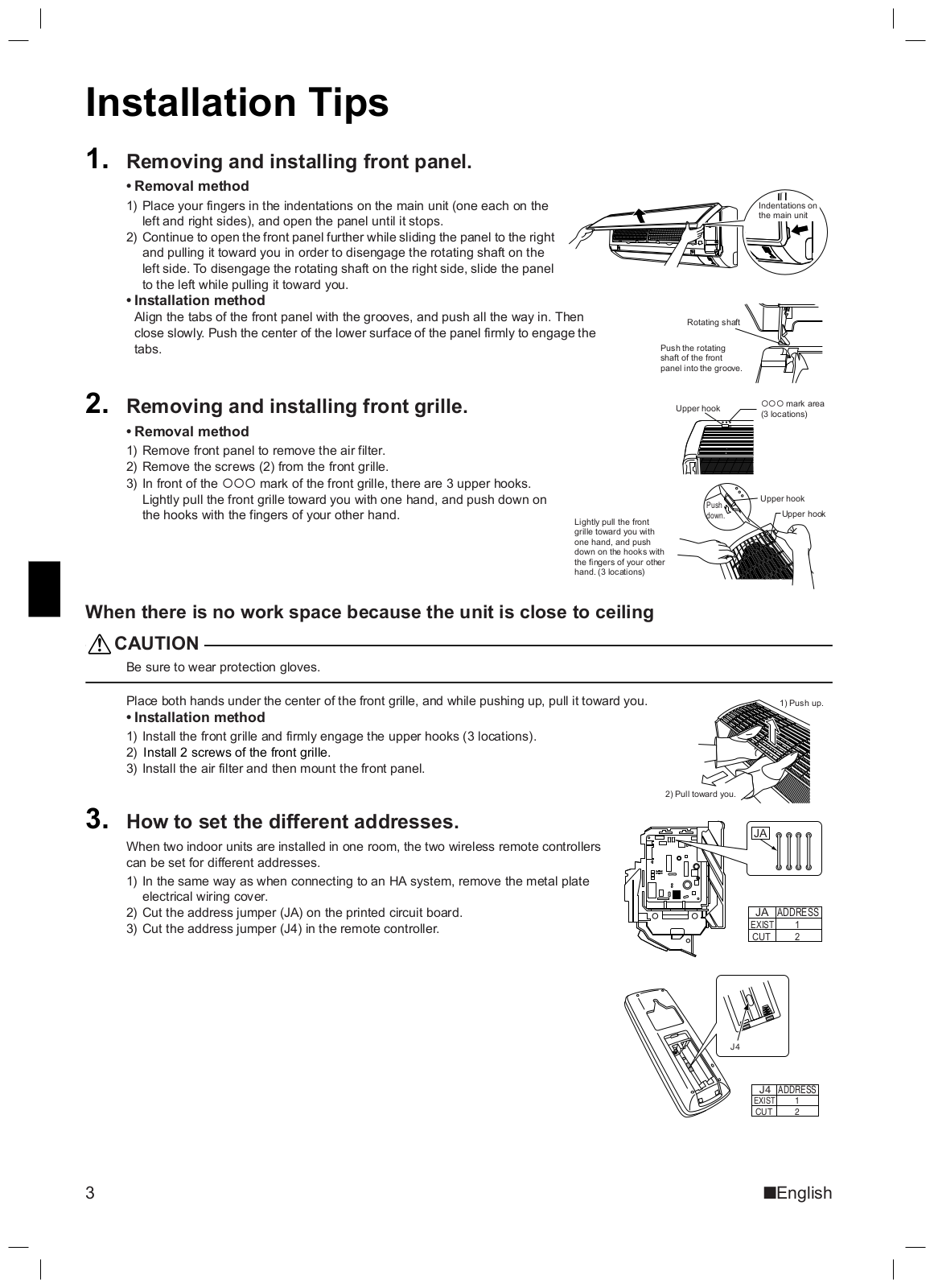
FTXB25BV1
2
FTXB25C
FTXB25C2V1B
75
FTXB35BV1
2
FTXB35C
FTXB35C2V1B
76
FTXB50BV1B
FTXB50CV1B
16
FTXB60BV1B
FTXB60CV1B
16
FTXB-C
FTXC20BV1B
5
FTXC20CV1B
48
FTXC25AV1B
2
FTXC25BV1B
5
FTXC25CV1B
48
FTXC35AV1B
2
FTXC35BV1B
5
FTXC35CV1B
48
FTXC50AV1B
2
FTXC50BV1B
5
FTXC50CV1B
48
FTXC60AV1B
2
FTXC60BV1B
5
FTXC60CV1B
48
FTXC71BV1B
5
FTXC71CV1B
48
FTXF20A2V1B
147
FTXF20A5V1B
55
FTXF20B5V1B
55
FTXF20C5V1B
62
FTXF25A2V1B
147
FTXF25A5V1B
55
FTXF25B5V1B
55
FTXF25C5V1B
62
FTXF35A2V1B
147
FTXF35A5V1B
55
FTXF35C5V1B
62
FTXF42C5V1B
57
FTXF50A2V1B
147
FTXF60A2V1B
147
FTXF71A2V1B
147
FTXG09HVJU
FTXG12HVJU
FTXG15HVJU
FTXG20LS
3
FTXG20LV1BS
63
FTXG-EV1BS
FTXG-EV1BW
FTXG-LS
2
FTXG-LW
2
Loading...
Loading...
Nothing found
FTXB25BV1
Operation manuals [ru]
80 pgs
4.22 Mb
0
Installation manuals
38 pgs
4.63 Mb
0
Table of contents
Loading...
Daikin FTXB25BV1, FTXB35BV1 Installation manuals
...
Daikin Installation manuals
Download
Specifications and Main Features
Frequently Asked Questions
User Manual
Download
Loading...
+
26
hidden pages
Unhide
You need points to download manuals.
1 point = 1 manual.
You can buy points or you can get point for every manual you upload.
Buy points
Upload your manuals