

Daikin FFQ35CXV1, FTXN45MV1B, FTXN50MV1B, FFQ50CXV1, FDMQ35CXV1 Technical Manual
...
TECHNICAL MANUAL
Split Unit Air Conditioner
Inverter Multi Split Series
MX-B Series
— Cooling only & Heatpump [50Hz] —
TM-5MSY-B-ST-A1
R410A


Table of Contents
i
Table of Contents
Nomenclature......................................................................................................................1
Indoor ............................................................................................................................1
Outdoor ..........................................................................................................................2
Product Line-Up .............................................................................................................3
Application Information .....................................................................................................6
Operating Range ...........................................................................................................6
Refrigerant Circuit Diagrams .........................................................................................7
Installation Guideline .....................................................................................................8
Engineering & Physical Data ...........................................................................................20
Performance Data .............................................................................................................23
Outline & Dimension ........................................................................................................26
Wiring Diagram .................................................................................................................30
Service & Maintenance ....................................................................................................36
Troubleshooting ...............................................................................................................38

ii

Nomenclature
1
Nomenclature
Indoor
FT(X) N 25 M V1 B
Region
Power Supply Symbol
V1: 1 Phase 50 Hz 240V
Generation/Series
M: M series
L: L Series
Capacity Indication
25: 2,500 kW
* It might differ with the actual rated capacity.
Always refer to engineering & physical data or
performance table
Refrigerant
N: R410A
Model
FT: Wall Mounted (Cooling Only)
FTX: Wall Mounted Inverter (Heatpump)
FLQ100E X V1
Power Supply Symbol
V1: 1 Phase 50 Hz 240V
Production
X: OYLM
Product Series
C: C series
E: E series
Capacity Indication
100: 10000 W
* It might differ with the actual rated capacity.
Always refer to engineering & physical data or
performance table
Model
FCQ: Ceiling Cassette 3ft x 3ft
FFQ: Ceiling Cassette 2ft x 2ft
FDMQ: Ceiling Concealed
FLQ: Ceiling Exposed
FHQ: Ceiling Exposed (140CXV1 model only)

Nomenclature
2
Outdoor
2 MX 45B G X V1
Power Supply Symbol
V1: 1 Phase 50 Hz 220~240V
Production
X: OYLM
Capacity Indication
45: ≈ 13,650 Btu/h [4kW]
50: ≈ 18,400 Btu/h [5.4kW]
60: ≈ 22,200 Btu/h [6.5kW]
80: ≈ 26,100 Btu/h [7.65kW]
* It might differ with the actual rated capacity.
Always refer to engineering & physical data or
performance table
Multi Split Inverter (Heatpump)
Indoor Quantity
2: 2 Indoor Units
3: 3 Indoor Units
4: 4 Indoor Units
Generation Minor Changes
Generation/Series
Nomenclature
3
Product Line-Up
Indoor Unit: Wall mounted
FTXN-MV1 Series
Model
Classifi cation
Panel (Handset)
PCB
Fin
Refrigerant Control
Air Purifi cation
Others
BRC52A61
C_2_01A-M
Hydrophilic (Blue)
Expansion Device
Without Expansion Device
Saranet Filter
Without Air Filter
Auto restart
Heatpump
FTXN25MV1B X X X X X X
FTXN45MV1B X X X X X X
FTXN50MV1B X X X X X X
Indoor Unit: Ceiling Cassette
FFQ-CXV1 / FCQ-EXV1 Series
Model
Classifi cation
Panel (Handset)
PCB
Fin
Refrigerant Control
Air Purifi cation
Others
BYCQ20CXW (BRC52A61)
C_2_01A-M
Hydrophilic (Blue)
Expansion Device
Without Expansion Device
Saranet Filter
Without Air Filter
Auto restart
Heatpump
FFQ25CXV1 X X X X X X
FFQ35CXV1 X X X X X X
FFQ50CXV1 X X X X X X

Nomenclature
4
Indoor Unit: Ceiling Concealed
FDMQ-C(2)XV1 Series
Model
Classifi cation
Panel (Handset)
PCB
Fin
Refrigerant Control
Air Purifi cation
Others
BRC51A61
C_2_01A-M
Hydrophilic (Blue)
Expansion Device
Without Expansion Device
Saranet Filter
Without Air Filter
Auto restart
Heatpump
FDMQ25C2XV1 X X X X X X
FDMQ35CXV1 X X X X X X
FDMQ50CXV1 X X X X X X
Indoor Unit: Ceiling Mounted
FLQ-EXV1 Series
Model
Classifi cation
Panel (Handset)
PCB
Fin
Refrigerant Control
Air Purifi cation
Others
BRC52A61
C_2_01A-M
Hydrophilic (Blue)
Expansion Device
Without Expansion Device
Saranet Filter
Without Air Filter
Auto restart
Heatpump
FLQ35EXV1 X X X X X X
FLQ50EXV1 X X X X X X

Nomenclature
5
Outdoor Unit
MX-B Series
Model
Classifi cation
Compressor
Fin
Refrigerant Control
Others
Others
DC Inverter Swing
Hydrophilic (Blue)
Expansion Device
Without Expansion Device
Drain Elbow
Drain Elbow
Heatpump
2MX45BGXV1 X X X X X
2MX50BGXV1 X X X X X
3MX60BGXV1 X X X X X
4MX80BGXV1 X X X X X
6
Application Information
Application Information
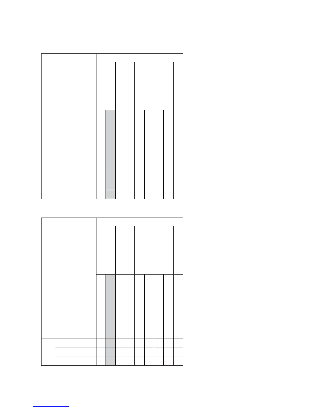
Operating Range
Ensure the operating temperature is in allowable range.
Heatpump - 2MX50BGXV1 / 3MX60BGXV1 / 4MX80BGXV1
Heating
Outdoor WB (°C)
Indoor DB (°C)
Cooling
Outdoor DB (°C)
Indoor WB (°C)
-16
15 20 27
18
46
43
10
12 2319
10
Heatpump - 2MX45BGXV1
Heating
Outdoor WB (°C)
Indoor DB (°C)
-16
15 20 27
18
10
Cooling
Outdoor DB (°C)
Indoor WB (°C)
12 19 23
46
43
10
The use of your air conditioner
outside the range of working
temperature and humidity can result
in serious failure.
7
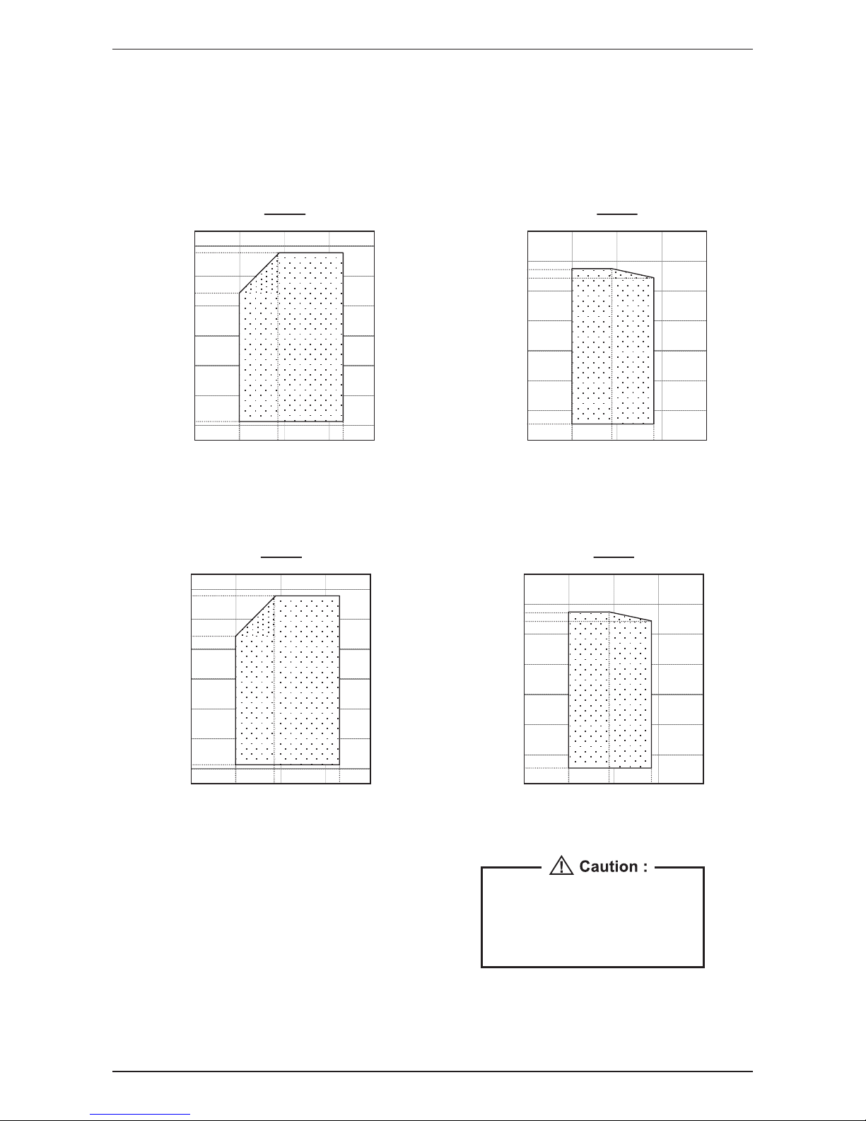
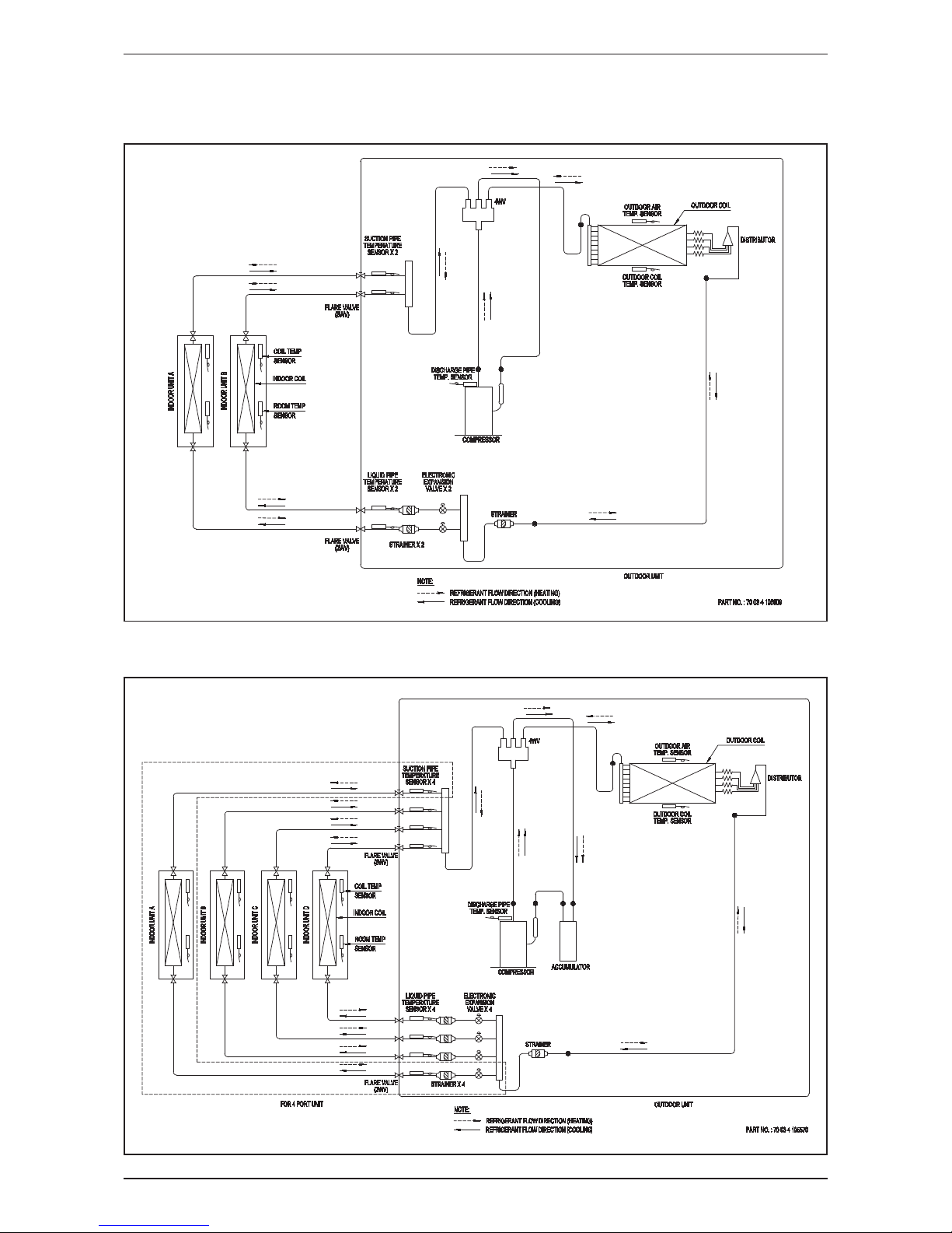
Application Information
Refrigerant Circuit Diagrams
Model: 2MX45BGXV1 / 2MX50BGXV1
Model: 3MX60BGXV1 / 4MX80BGXV1

8
Application Information
Installation Guideline
Installation of Outdoor Unit
• The outdoor unit must be installed in such a way, so as to prevent short circuit of the hot discharged
air or obstruction to the smooth air fl ow. Please follow the installation clearance shown in the fi gures
below. Select the coolest possible place where intake air temperature is not greater than the outside air
temperature (maximum 45°C/113°F).
• Where a wall or other obstacle is in the path of outdoor unit’s intake or exhaust airfl ow, follow the
installation guidelines below.
• For any of the below installation patterns, the wall height on the exhaust side should be 1200mm or less.
More than 100
Wall facing one side Wall facing two sides
Wall facing three sides
More than 350
More than 50
More than 50
Top View
Top View
Side View
More
than 100
More than 350
More than 100
More than 350
More than 50
Unit : mm
1200
or less
• Before installing the piping and connecting cord, please remove the access panel and plastic valve cover
for easy access. Refer to fi gures shown below.
• There are 2 holes on the base of Outdoor Unit for
condensed water to fl ow out. Insert the drain elbow
to one of the holes.
• To install the drain elbow, fi rst insert one portion
of the hook to the base (portion A), then pull the
drain elbow in the direction shown by the arrow
while inserting the other portion to the base. After
installation, check to ensure that the drain elbow
clings to base fi rmly.
• If the unit is installed in a snowy and chilly area,
condensed water may freeze in the base. In such
case, please remove plug at the bottom of unit to
smooth the drainage.
BASE
Plug
A
DRAIN
ELBOW
DRAIN
ELBOW
9
Application Information
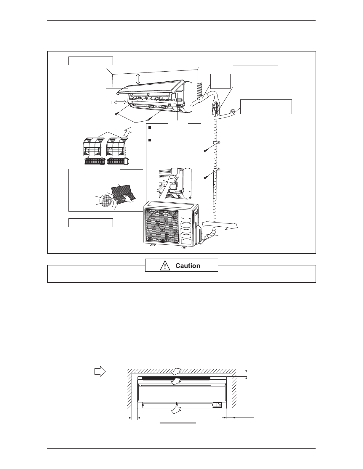
Installation Diagram
Wall Mounted
Indoor Unit
Outdoor Unit
50mm or more from walls
(on both sides)
Front panel
30mm or more from ceiling
M4 x 12L
Air filter
Air-Purifying Filter with
bacteriostatic virustatic function (2)
Air filter
Air-Purifying Filter with
bacteriostatic virustatic
function
Filter frame
Tab
250mm from wall
Service lid
Opening service lid
Service lid is opening/closing
type.
Opening method
1) Remove the service lid
screws.
2) Pull out the service lid
diagonally down in
the direction of the arrow.
1) Pull down.
Caulk pipe
hole gap
with putty.
Cut thermal insulation
pipe to an appropriate
length and wrap it with
tape, making sure that no
gap is left in the insulation
pipe's cut line.
Wrap the insulation pipe with
the finishing tape from bottom
to top.
• Before installing the unit, ensure that the power supply matches the power requirement of the air conditioner.
Installation of Indoor Unit
Service Space
Install the indoor unit at a location with the following requirements
• Location is suitable for wiring, piping and drainage.
• No obstruction of air fl ow into and out of unit where cooler air can be evenly distributed.
• Ensure that air discharge is not short circuited with air intake.
• Ensure that wall is suffi ciently strong, rigid, fl at, perpendicular and vibration free.
• Where air fi lter cassette can be slided in or out easily.
• Where there is no danger of fl ammable gases.
• Where there is no direct sunlight on unit.
min. 50
min. 30
(Space for
maintenance)
min. 50
(Space for
maintenance)
(Space for
performance)
Air flow
(Indoor)
Required space

10
Application Information
Ceiling Cassette
Drain Piping Thermal Insulation
Wrap the insulated pipe with the
finishing tape from bottom to top
Air Discharge Louver
Air Filter
(behind the grille)
Front Panel
Air Intake Grille
Preliminary Site Survey
• Electrical supply and installation is to confi rm to local authority’s (e.g. National Electrical Board) codes and
regulations.
• Voltage supply fl uctuation must not exceed ± 10% of rated voltage. Electricity supply lines must be
independent of welding transformers which can cause high supply fl uctuation.
• Ensure that the location is convenient for wiring, piping and drainage.
• The indoor unit must be installed in such that free from any obstacles in path of cool air discharge and
warm air return, and must allow spreading or air throughout the room (near the centre of the room).
• Clearance must be provided for the indoor unit from the wall and obstacles as shown in the fi gure.
Min 1.0 m
Max 3.0 m
Floor
Obstacles
Min 0.5 m Min 0.5 m
Min 0.5 m
Max 3.0 m
Beam
• The installation place must be strong enough to support a load of 4 times the indoor unit weight to avoid
amplifying noise and vibration.
• The installation place (handling ceiling surface) must be level and the height in the ceiling is 350mm or
more.
11
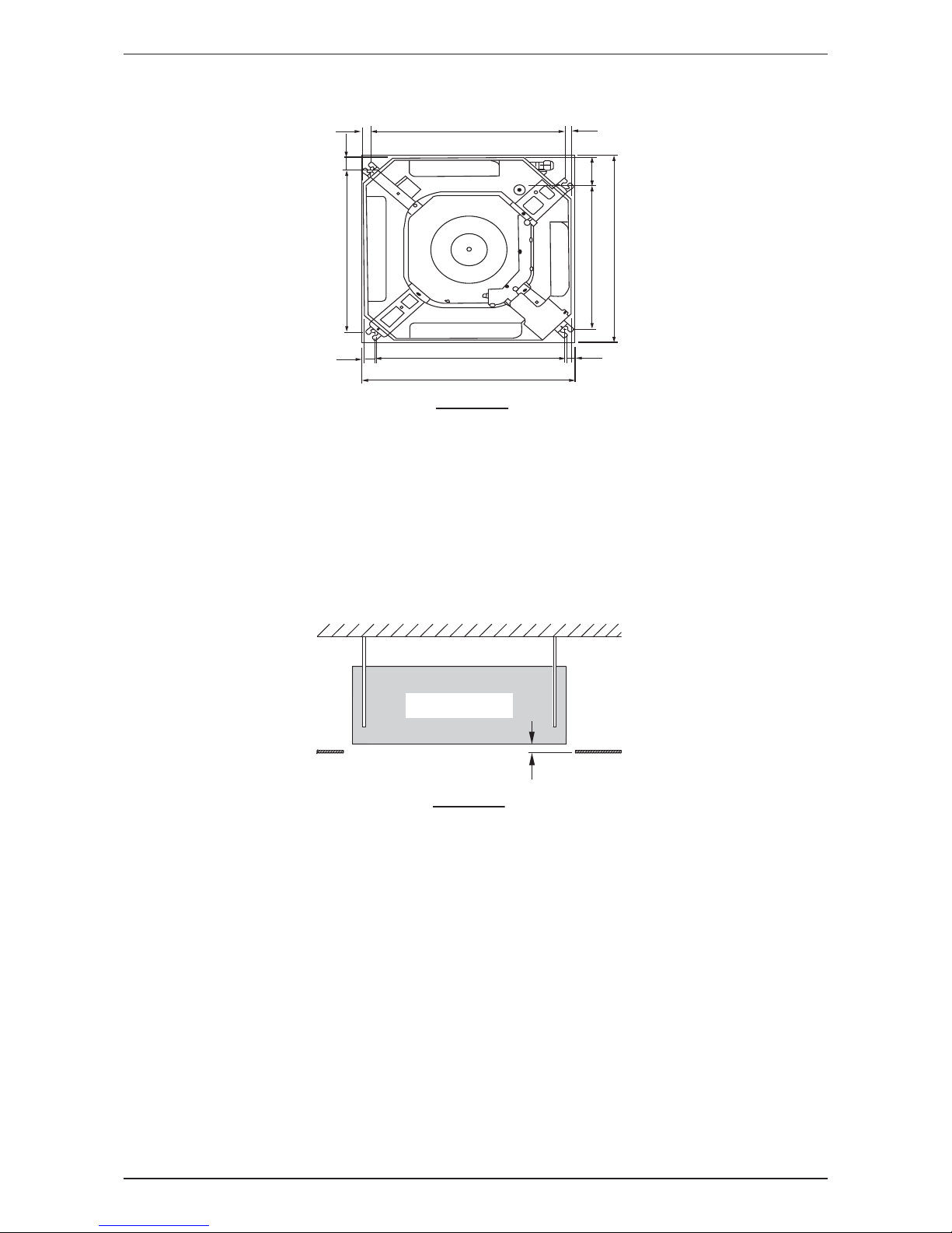
Application Information
Unit Installation
15.0
538.0
18.0
38.0
505.0
32.0
580.0 ~ 610mm (CEILING OPENING MEASUREMENT)
580.0 ~ 610mm (CEILING OPENING MEASUREMENT)
529.0
88.0
448.0
19.0
FFQ-CXV1
• The indoor unit must be away from heat and steam sources (avoid installing it near an entrance).
• Measure and mark the position for the hanging rod. Drill the hole for the angle nut on the ceiling and fi x the
hanging rod.
• The installation template is extended according to temperature and humidity. Check on dimensions in
using.
• The dimensions of the installation template are same as those of the ceiling opening dimensions.
• Before ceiling laminating work is completed, be sure to fi t the installation template to the indoor unit.
Note: Be sure to discuss the ceiling drilling work with the installers concerned.
Unit Hanging
Indoor Unit
Ceiling
Board
30.0mm
FFQ-CXV1
• Confi rm the pitch of the hanging rod is 770mm x 622mm sharp.
• Hold the unit and hand it on the hanging rod with the nut and washer.
• Adjust the unit height to 35.0mm between the indoor unit bottom surface and the ceiling surface.
• Confi rm with a level gauge that the unit is installed horizontally and tighten the nut and bolt to prevent unit
falling and vibration.
• Open the ceiling board along the outer edge of the paper installation template.
 Loading...