

Daikin EWWQ-AJYNN Service Manual
ESIE07-05
Service Manual
EWWQ-AJYNN
Water-cooled screw chillers

IMPORTANT NOTICE
This manual for the EWWQ-AJYNN chillers is a draft. Not all information on this chiller
is already present in this service manual.
However, together with the installation & operation manual and the databook, this
manual should provide you with enough information to do maintenance and
troubleshooting on this unit.


1
Introduction ESIE 07-05
1.2 About This Manual
3
4
Purpose of the
manual
Inspection When the equipment is received, all items on the bill of lading should be carefully checked to insure a
Responsibilities Daikin declines all present and future responsibilities referred to injuries to people and damage to
Servicing and
maintenance
The manual allows the installer and the operator to perform correctly all the operations required for the
installation and maintenance of the chiller without provoking any damages to the unit or to the qualified
personnel.Therefore the manual is essential to help qualified personnel that have to arrange the
equipment to provide the correct installation in accordance with local codes and regulation.
complete shipment. All units should be carefully checked and all shipping damage should be reported
to the carrier. The unit serial plate should be checked before unloading the unit to be sure that it agrees
with the power supply available. Physical damage to unit after acceptance is not Daikin’s
responsibility.
things and unit, coming from operators negligence, the unrespected installation/maintenance data
carrier in this manual, the lacking of the current regulations respect referred to the safety of the
equipment and the qualified personnel.
Servicing and maintenance of these unit must carried out by experienced personnel with specific
training refrigeration. Regular checking of safety devices should be carri ed out but routine
maintenance should be out in line with the recommendations list in the main section. The simple
design of the refrigeration circuit minimizes potential problems during normal unit operation.
5
ii

ESIE 07-05 Introduction
1.3 Characteristics
General description Daikin introduces their newest water cooled screw chillers equipped with new single screw
compressors.
Daikin water cooled EWWQ-AJYNN chillers equipped with 1, 2, 3 and 4 screw compressors are a new
range of the unit using the StarGateTM Frame 4 single screw compressors. They are manufactured
by Daikin to satisfy the requirements of the consultants and the end user. Daikin EWWQ_AJYNN units
are designed to minimise energy costs while maximising the refrigeration capacities. Once again
Daikin has developed a line of chillers unsurpassed in performance and quality that will meet the most
stringent requirements of comfort cooling, ice storage and process applications.
3
4
5
iii

1
3
Introduction ESIE 07-05
1.4 Safety Measures
The unit must be suitably clamped to the ground.
It is necessary to follow these cautions and warnings:
■ The unit must be lifted only by using the proper tools able to support the weight of the unit.
■ No admittance to unauthorized or unqualified personnel should be allowed.
■ No operation on electrical components is allowed without having switched off electricity supply.
■ No operation on electrical components is allowed without using insulated platforms; no water or
moisture should be present.
■ All the operation on refrigerant circuit and pressurised components are to be performed by qualified
personnel only.
■ Compressor substitution or oil addition must be performed by qualified personnel only.
■ Avoid contamination of unrelated bodies into the water piping during the unit connection to the
water system.
■ It is necessary that a mechanical filter is fitted to the piping connected to the exchangers entry.
4
5
iv

ESIE 07-05 Introduction
1.5 Installation
Before any operation please check the instruction for use.
Warning Installation and maintenance are to be performed only by qualified personnel who are familiar with
local codes and regulations, and who are experienced with this type of equipment. Must be avoided
the installation of the unit in places that could be considered dangerous for maintenance operations.
Receiving and
handling
Location A levelled and sufficiently strong floor is required. If necessary, additional structural members should
Compressor
condensation
Water treatment If unit is operating with a cooling tower, clean and flush cooling tower. Make sure tower "blowdown" or
Inspect the unit immediately after receipt for possible damage. The unit is shipped ex-factory and all
claims for handling and shipping damage are the responsibility of the consignee. Leave the shipping
skid in place until the unit is in final position. This will aid in handling the equipment. Use extreme care
when rigging the equipment to prevent damage to the control centre, or refrigerant piping. See
Dimensional Data for the centre of gravity of the unit.
be provided to transfer the weight of the unit to the nearest beams.
Rubber-in-shear isolators can be furnished and field placed under each corner of the package. A
rubber anti–skid pad should be used under isolators if hold-down bolts are not used.
Vibration isolator in all water piping connected to the chiller are recommended to avoid straining the
piping and transmitting vibration and noise.
Condensation occurs on the compressor surface when the temperature of the compressor surface is
lower than the ambient dew point temperature. Drain pans with drain connections are provided
underneath each compressor to collect the condensate. The compressor motor housing extends past
the drain pans. Install a floor drain close to the unit to collect condensate from motor housing and
condensate pans.
bleedoff is operating. Atmospheric air contains many contaminants which increases the need for water
treatment. The use of untreated water may result in corrosion, erosion, sliming, scaling, or algae
formation. A water treatment service is recommended. Daikin is not responsible for damage or faulty
operation from untreated or improperly treated water.
3
4
5
Head pressure
control, tower
system
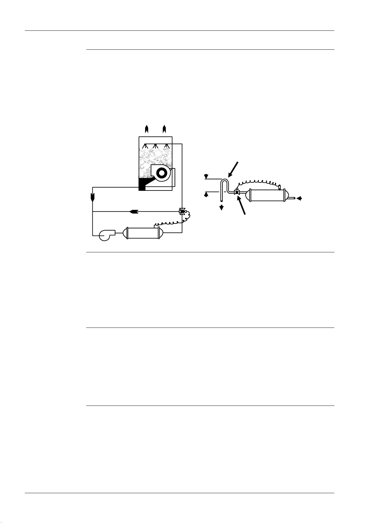
The minimum entering water temperature to the condenser must not be lower than 15 °C at full tower
water flow. If lower temperature water is used, the flow must be reduced proportionally. Use a
three-way bypass valve around the tower to modulate the condenser water flow. Figure 1 shows a
three-way pressure actuator water regulating valve used for cooling applications. This regulating valve
will assure an adequate condensing pressure if the inlet condenser water temperature falls below
15 °C.
v
Introduction ESIE 07-05
1
3
4
Head pressure
control, well water
system
When using city or well water for condensing refrigerant, install a normally closed direct acting water
regulating valve in the outlet piping of the condenser. This regulating valve will assure an adequate
condensing pressure if the inlet condenser water temperature falls below 15 °C. The condenser
service valve provides a pressure tap for the regulating valve. The valve can modulate in response to
head pressure. On shutdown, the valve closes, preventing water from siphoning out of the condenser.
Siphoning causes condenser waterside drying and accelerates fouling. If a valve is not used, Figure 2
illustrates the recommendation of a loop at the outlet. Size the loop he ight (H) to offset the negative
pressure caused by the siphoning effect. A vacuum breaker may be required.
Loop required when no
regulating valve is used
Cooling Tower
Condenser
H
To drain
Direct acting water
regulating valve
From main
condenser
pump
5
Temperature and
waterflow
limitations
Evaporator freeze
protection
EWWQ-AJYNN units are designed to operate in conditions from -8 °C to +15 °C leaving water
temperature on the evaporator side and +15 °C to +55 °C entering water temperature on the
condenser side. Glycol in the evaporator is required on all applications below +4 °C leaving evaporator
fluid temperature. The maximum allowable water temperature to the cooler in a non-operating cycle is
40 °C. The non-operating leaving condenser water temperature maximum is 46 °C. Flow rates below
the minimum values shown in the evaporator and condenser pressure drop curves may cause
freeze-up problems, scaling and poor control. Flow rates above the maximum values shown in the
evaporator and condenser pressure drop curves will result in unacceptable pressure drops, excessive
nozzle and tube erosion and possibly cause tube failure.
When freeze protection is a concern, do the following:
■ If the unit will not be operated during the winter, drain and flush the evaporator and chilled water
piping with glycol. Drain and vent connections are provided on the evaporator.
■ When using a cooling tower, add glycol solution to the chilled water system. Freeze point should
be approximately 6°C below minimum design ambient temperature.
■ Insulate field water piping, especially on the chilled water side.
Note: Freeze damage is not considered a warranty failure and is not the responsibility of Daikin.
vi

ESIE 07-05 Introduction
Water piping Due to the variety of piping practices, it is advisable to follow the recommendations of local authorities.
They can supply the installer with the proper building and safety codes required for a safe and proper
installation.
Basically, the piping should be designed with a minimum number of bends and changes in elevation
to keep system cost down and performance up. It should contain:
1 Vibration eliminators to reduce vibration and noise transmission to the building.
2 Shutoff valves to isolate the unit from the piping system during unit servicing.
3 Manual or automatic air vent valves at the high points of the system. Drains at the low parts in the
system. The evaporator should not be the highest point in the piping system.
4 Some means of maintaining adequate system water pressure (e.g., expansion tank or regulating
valve).
5 Water temperature and pressure indicators located at the unit to aid in unit servicing.
6 A strainer or some means of removing foreign matter from the water before it enters the pump. The
strainer should be placed far enough upstream to prevent cavitation at the pump inlet (consult
pump manufacturer for recommendations). The use of a strainer will prolong pump life and help
maintain high system performance levels.
7 A strainer should also be placed in the supply water line just prior to the inlet of the evaporator. This
will aid in preventing foreign material from entering and decreasing the performance of the
evaporator.
8 The shell-and-tube evaporator has a thermostat and heating cable to preven t freeze-up down to
-28°C. Any water piping to the unit must also be protected to prevent freezing.
9 If the unit is used as a replacement chiller on a previously existing piping system, the system should
be thoroughly flushed prior to unit installation and then regular chilled water analysis and chemical
water treatment is recommended immediately at equipment start-up.
10 In the event glycol is added to the water system, as an afterthought for freeze protection, recognize
that the refrigerant suction pressure will be lower, cooling performance less, and water side
pressure drop greater. System safety devices such as freeze protection and low pressure
protection must be reset.
3
4
5
Prior to insulating the piping and filling the system, a preliminary leak check should be made.
Chilled water
thermostat
Refrigerant charge All units are designed for use with HFC-410A and are shipped with a full operating charge. The
Flow switch A water flow switch must be mounted in either the entering or leaving water line to insure that there
Glycol solutions Use industrial grade glycols only. Do not use an automotive grade antifreeze. Automotive antifreeze
The EWWQ-AJYNN water-cooled chiller is equipped with the MicroTech II leaving water controller. Be
careful when working around the unit to avoid damaging lead wire s and sensor cables. Check lead
wires before running the unit. Avoid rubbing the lead wires on the frame or other components. Verify
the lead wires are firmly anchored. If the sensor is removed from the well for servicing, do not wipe off
the heat conducting compound supplied in the well.
operating charge for each unit is shown in the Physical Data Table.
will be adequate water flow to the evaporator before the unit can start. This will safeguard agains t
slugging the compressors on start-up. It also serves to shut down the unit in the event that water flow
is interrupted to guard against evaporator freeze-up.
contains inhibitors that will cause plating on the copper tubes within the chiller evaporator. The type
and handling of glycol used must be consistent with local codes.
vii

1
3
4
Introduction ESIE 07-05
1.6 Standard Accessories (furnished on basic unit)
Star Delta Compressors starter For low inrush current and reduced starting torque.
Phase monitor The phase monitor controls the voltage values on the
supply line stopping the unit when the calibration
threshold is reached (± 10%). This safety device is
automatically reset.
Evaporator connection water side
Victaulic
Condenser connection water side
Victaulic
Hour run meter Digital compressors hour run meter.
General fault contactor Contactor for the alarm warning.
Brine double set point version Dual leaving glycol mixture temperature setpoints.
Compressor thermal overload relays Safety devices against compressor motor overloading
Flow switch Supplied separately to be wired and installed on the
Rubber type antivibration mounts Supplied separately, these are positioned under the
Hydraulic joint with gasket for an easy and quick w ater
connection.
Hydraulic joint with gasket for an easy and quick w ater
connection.
The lower setpoint can go down to -8 °C.
in addition to the normal protection envisaged by the
electrical windings.
evaporator water piping (by the customer).
base of the unit for “floor” installation.
5
viii
ESIE 07-05 Introduction
1.7 Options (on request)
100% total heat recovery (OPTR) Produced with tube bundle placed in a single shell
with the water condensers. Heat exchangers heads
are provided with 2 connections for entering/leaving
heat recovery water and 2 separate connections for
condensing water.
Partial heat recovery (OPPR) Produced with plate to plate heat exchangers installed
on discharge side of compressor hot gas. These allow
hot water to be produced up to a maximum
temperature of + 50 °C.
Ampmeter and voltmeter (OP57) Digital meters of unit drawn amperes and voltage
values, installed on the electrical control panel.
Condenser power factor correction
(OPPF)
Suction line shut off valve (OP12) Suction shut-off valve installed on the suction port of
Cu-Ni 90-10 condenser (OPNI) To work with sea water the heat exchangers are fitted
Witness tests The units are normally tested at the test bench prior to
Soft start (OPSS) Electronic starting device to reduce inrush current. An
Installed on the electrical control panel to ensure it
conforms to the plant rules. (DAIKIN advises
maximum 0.9).
the compressor to facilitate maintenance operation.
with Cu-Ni tubes and special protection inside the end
covers.
the shipment. On request, a second test can be
carried out, at customer’s presence, in accordance
with the procedures indicated on the test form. (Not
available for units with Glycol mixtures).
overload protection is included.
3
4
5
ix
ESIE07-05
4
Part 2
Functional Description
2
Introduction This part gives more detailed information on the functions and controls of the unit. This information is
used as background information for troubleshooting. An extensive overview of the functioning of the
controller is also given in this part. Knowledge of the controller is essential to gather information prior
to servicing and troubleshooting.
What is in this part? This part contains the following chapters:
Chapter See page
1–The Digital Controller 2–3
2–Functional Control 2–47
3
4
5
Part 2 – Functional Description 2–1

1
2
3
ESIE07-05
5
2–2 Part 2 – Functional Description
ESIE07-05 The Digital Controller
Part 2
1 The Digital Controller
1.1 What Is in This Chapter?
Introduction This chapter gives more detailed information about the controller and the software. Understanding
these functions is vital when diagnosing a malfunction, which is related to system architecture or
software.
Overview This chapter contains the following topics:
Topic See page
1.2–General Description 2–4
1.3–Main Control Software Features 2–5
1
2
3
4
1.4–Component Description Digital controller 2–6
1.5–Controller Menu’s 2–22
5
Part 2 – Functional Description 2–3
1
2
3
The Digital Controller ESIE07-05
1.2 General Description
Introduction The Micro te ch II C Plus control panel contains a microprocessor based controller which provides all
monitoring and control functions required for the safe, efficient operation of the Chiller. The operator
can monitor all operating conditions by using the panel's built in 4 line by 20 character keypad/display
or by using an IBM compatible computer running MicroPlant monitor software release 2.0 and later. In
addition to providing all normal operating controls, the MicroTech II CV Plus controller monitors all
safety devices on the unit and will take corrective action if the chiller is operating of it's normal design
conditions. If a fault condition develops, the controller will shut the system down and activate an alarm
output. Important operating conditions at the time an alarm condition occurs are retained in the
controller's memory to aid in troubleshooting and fault analysis.
The system is protected by a password scheme which only allows access by authorized personnel. A
password must be entered into the panel keypad by the operator before any configuration may be
altered
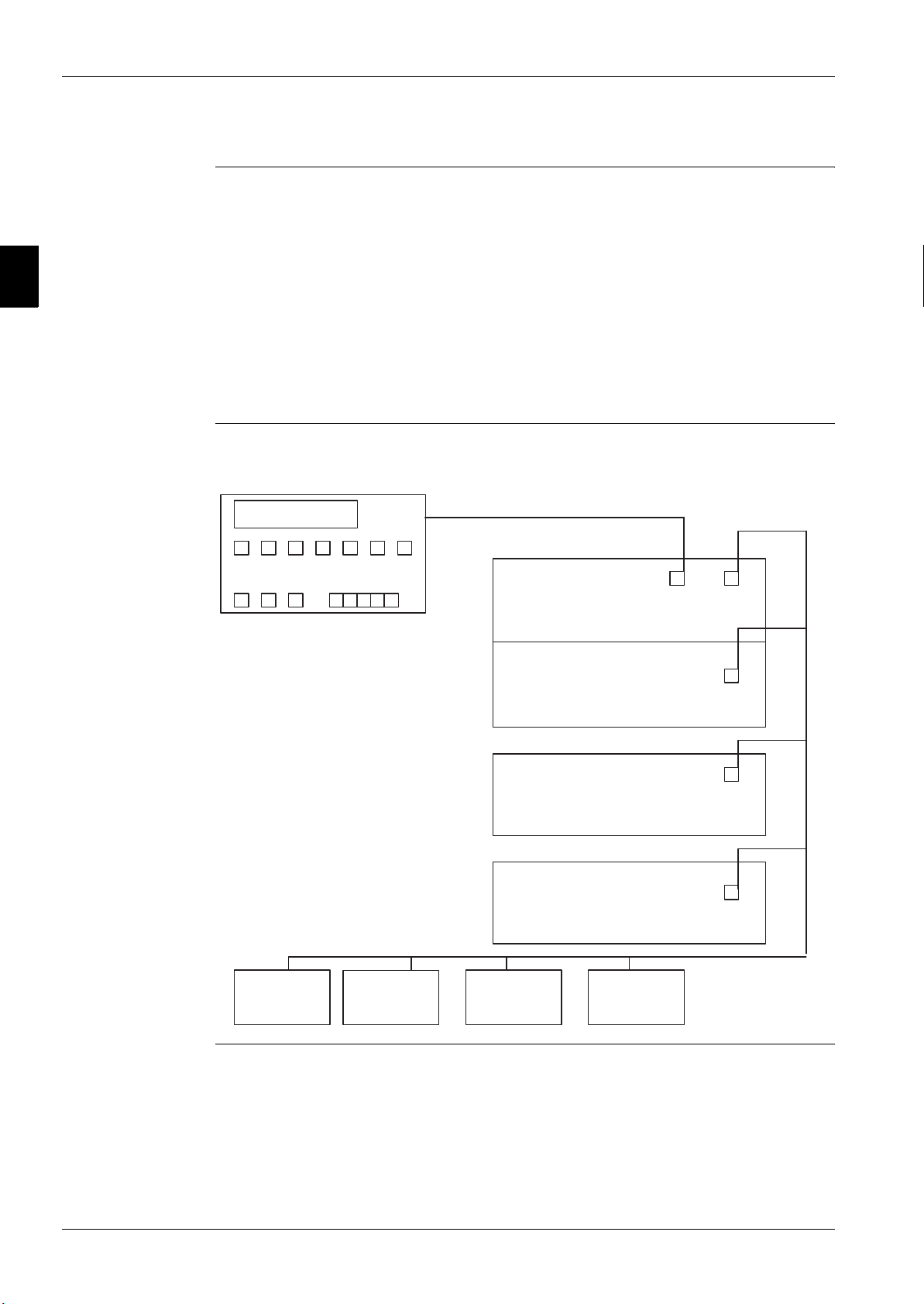
Lan layout The illustration below shows the Lan layout.
DISPLAY pLan
4
5
MASTER BOARD
COMPRESSOR #1
SLAVE BOARD
COMPRESSOR #2
SLAVE BOARD
COMPRESSOR #3
SLAVE BOARD
COMPRESSOR #4
DRIVER
EEXV #1
2–4 Part 2 – Functional Description
DRIVER
EEXV #2
DRIVER
EEXV #3
DRIVER
EEXV #4

ESIE07-05 The Digital Controller
1.3 Main Control Software Features
■ Control of evaporator outlet or condenser outlet or both temperature.
■ Control of leaving water within a ± 0.1 °C (with a steady-state load).
■ Management of sudden load reduction up to 50% with max 3°C controlled temperature obscillation
■ Readout of all unit operating main parameters (temperature, pressures, etc.)
■ Automatic control of primary evaporator and condenser pumps.
■ Condensation control with step logic, single or double fan speed controllers and mixed step+speed
control (speedtroll)
■ Control up to 4 steps of cooling tower plus bypass valve with proportional signal 0-10 Vdc
■ Setting of a double setpoint with local or remote switch. This function allows to modify the local
setpoint between two values previously settled.
■ Setpoint override using an external signal (4-20 mA), outside ambient temperature or evaporator
return temperature.
■ Adjustable Max Pull-Down rate reduces under-shoot during loop pull-down.
■ Hot Chilled Water Start feature allows the unit startup without any problem also with high
temperature evaporator water.
■ SoftLoad feature reduces electrical consumption and peak demand charges during loop pulldown.
■ Unit Limiting feature allows to limit electrical consumption based either on current absorption
(current limit (SPN)) or on demand capacity (demand limit).
■ Panel mounted 15 key keypad for a rapid interface. Operator can log chiller operating conditions
on the backlight display 4 line by 20 character.
■ Four levels of security protection against unauthorized changing.
■ Diagnostic System of compressors constituted by the memorization of the last ten alarms, showing
the date, the time and operating conditions at the time the alarm occurred.
■ Weekly and yearly start-stop time schedule
■ Easy integration into building automation systems via separate 4-20 mA signals for chilled water
reset and demand limiting.
■ Communications capabilities for remote monitoring, changing of setpoint, trend logging, alarm and
event detection, via a compatible IBM-PC where is installed MICROPLANT 2.0 software.
■ BAS communication capability via Modbus, LonWork, Johnson Metasys
■ Remote communications capabilities via modem (up to 8 chillers with Gateway Modem).
■ Remote communications capabilities via GSM Modem.
1
2
3
4
5
Part 2 – Functional Description 2–5
1
2
3
The Digital Controller ESIE07-05
1.4 Component Description Digital controller
Overview This chapter contains the following topics:
Topic See page
1.4.1–Control Panel 2–7
1.4.2–Main Board 2–8
1.4.3–EEXV Valve Driver 2–10
1.4.4–Meaning of the Driver EEXV Status LEDs 2–12
1.4.5–Addressing of pLAN 2–13
1.4.6–Controller Input/Output 2–14
1.4.7–Display and Keypad 2–19
4
5
2–6 Part 2 – Functional Description
ESIE07-05 The Digital Controller
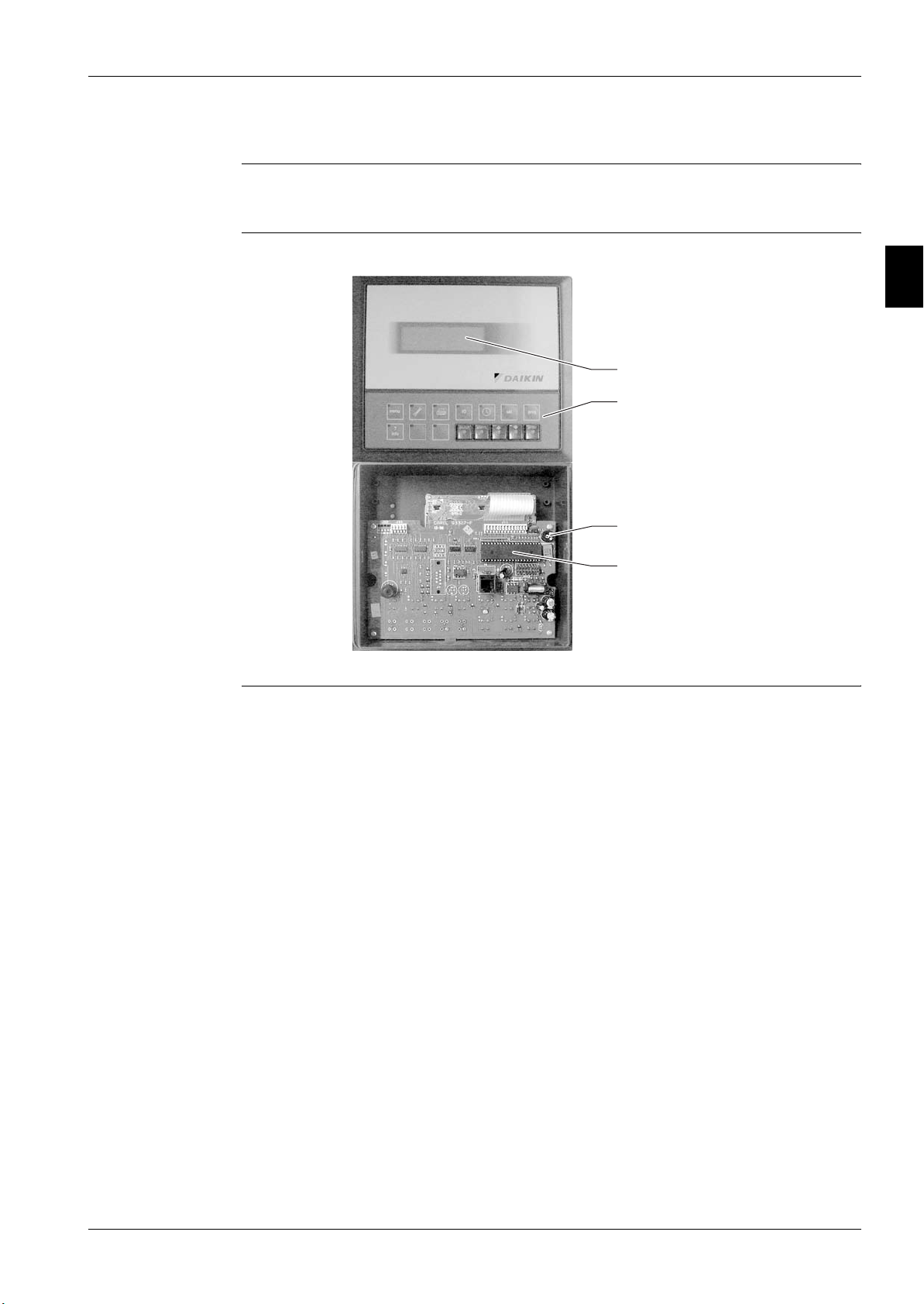
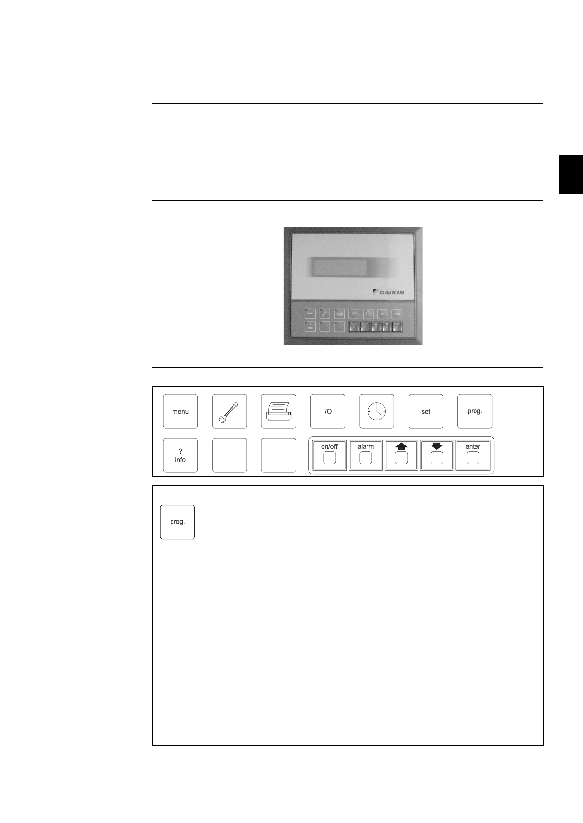
1.4.1 Control Panel
Introduction The Control Panel is constituted by the backlight display 4 line by 20 character and by the 15 key
keypad. In this chapter we will described this functions.
Frontal and back
view
Backlight Display
1
2
Keys
Trimmer for brightness
adjustment
Addressing Microswitches
3
4
5
Part 2 – Functional Description 2–7
1
2
3
The Digital Controller ESIE07-05
1.4.2 Main Board
Introduction The control board contains the hardware and the software necessary to monitor and to control the unit.
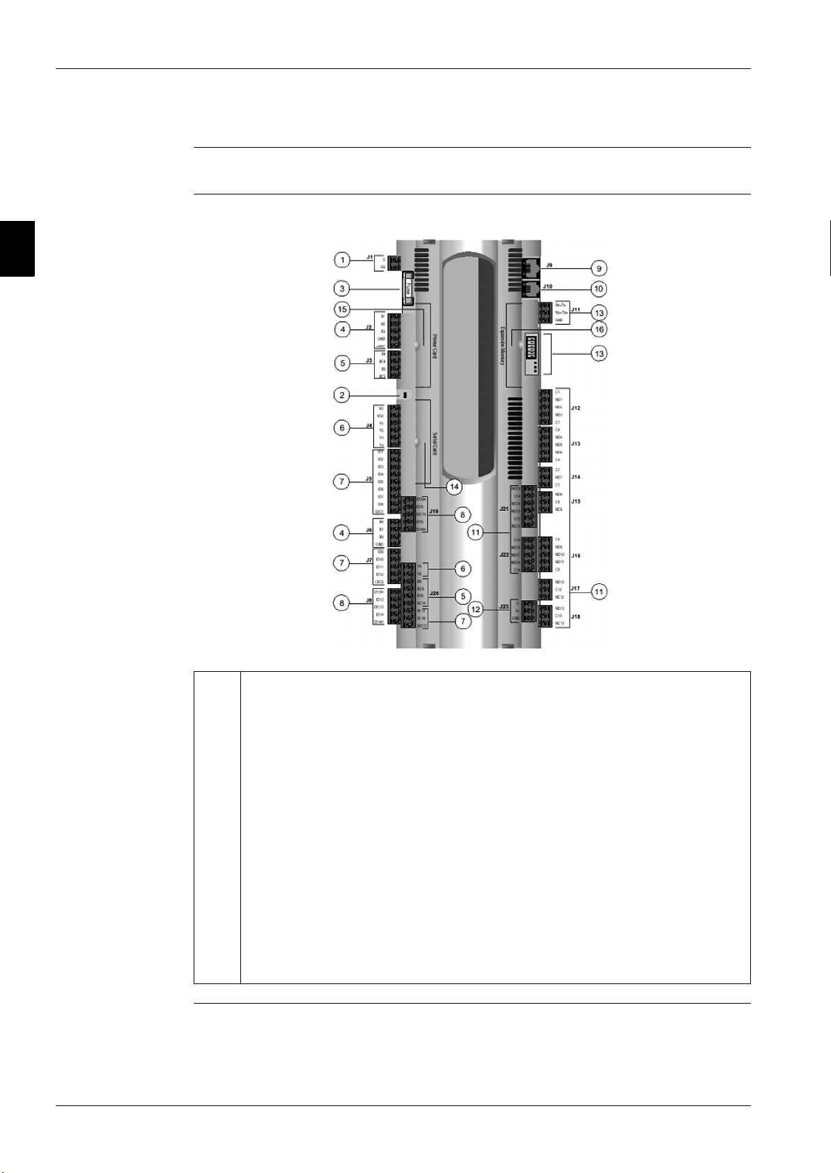
Main Board The figure below shows the main board:
4
5
1 Power supply G (+), G0 (-)
2 Status LED
3 Fuse 250Vac
4 Universal analog inputs (NTC, 0/1V, 0/10V,0/20mA, 4/20mA)
5 Passive analog inputs (NTC, PT1000, On- off)
6 Analog outputs 0/10V
7 24Vac/Vdc Digital inputs
8 230Vac or 24Vac/Vdc Digital inputs
9 Synoptic terminal connection
10 Standard terminal (and program download) connector
11 Digital outputs (relays)
12 Expansion board connection
13 pLAN connection and microswitches
14 Serial card connection
15 Printer card connection
16 Memory expansion connection
2–8 Part 2 – Functional Description

ESIE07-05 The Digital Controller
pLAN addressing
microswitches
R G V
ON
1
OFF
2
3
4
5
Part 2 – Functional Description 2–9
1
2
3
The Digital Controller ESIE07-05
1.4.3 EEXV Valve Driver
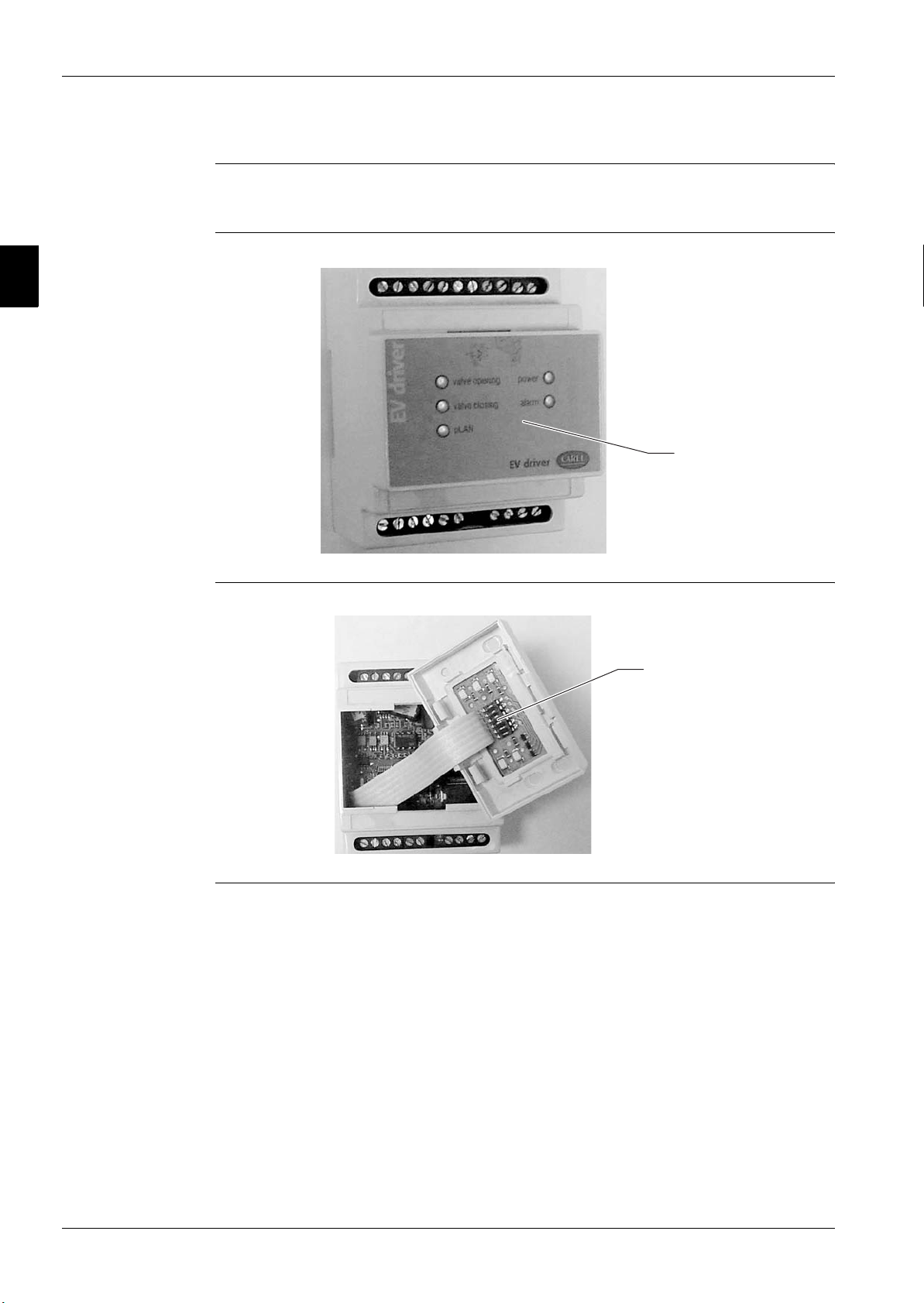
Introduction The valve drivers contai n the software for the control of the electronic expansion valve and are
connected to the battery group which provide to close valve in case of power failure.
Driver
Status Led
4
5
Inside of driver
Addressing
Microswitches
2–10 Part 2 – Functional Description
ESIE07-05 The Digital Controller
y
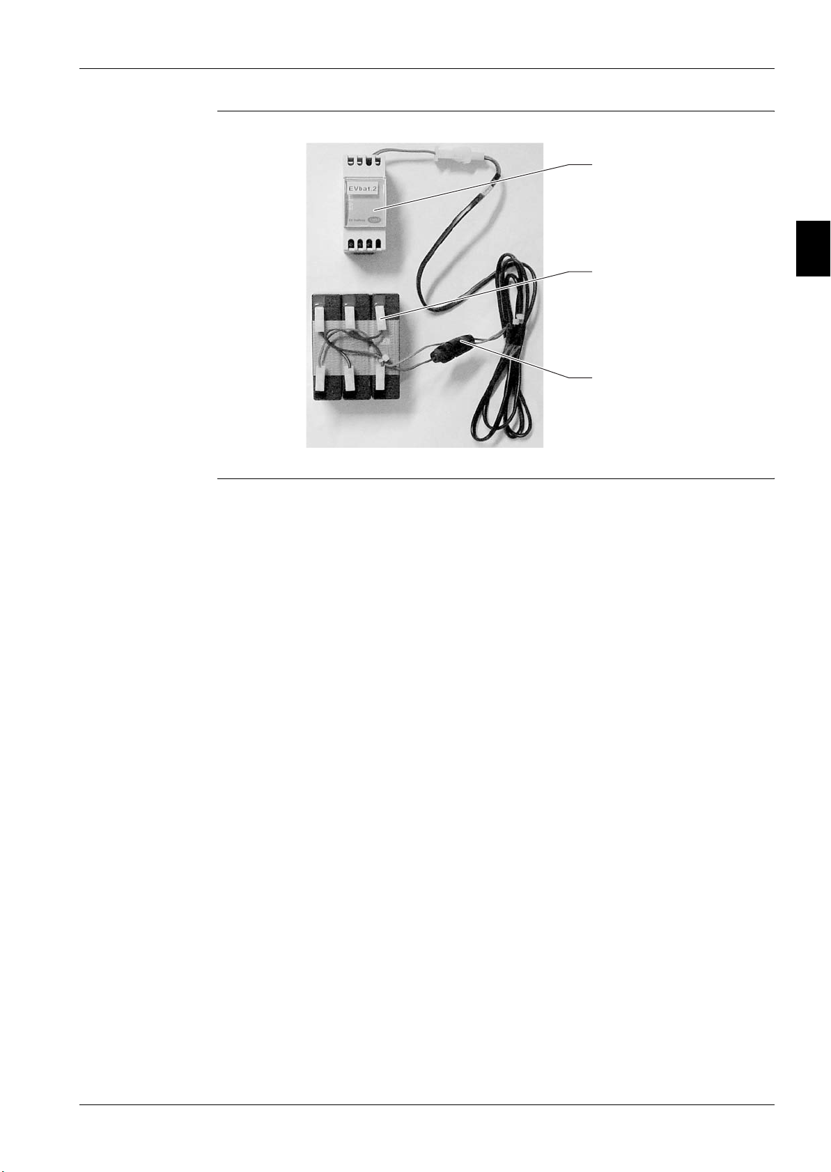
Battery assembly
1
Battery charger
2
Chargeable Batter
3
10 Amp Fuse
4
5
Part 2 – Functional Description 2–11
1
2
3
The Digital Controller ESIE07-05
1.4.4 Meaning of the Driver EEXV Status LEDs
Normal conditions Under normal conditions five(5) LED indicates:
■ POWER: (yellow) remains On in presence of supply. Remains Off in case of battery operation
■ OPEN: (green) Flashing during the valve opening. On when valve is fully open.
■ CLOSE: (green) Flashing during the valve closing. On when valve is fully close.
■ Alarm: (red) On or flashing in case of hardware alarm.
■ pLAN: (green) On during the normal working of pLAN.
Alarm situations In presence of critical alarm situations, the combination of the LED’s will identify the alarm as shown
below. In case more than one alarm is present, the alarm with the highest priority will be visualized.
Highest priority is level 7.
Alarms that stop the system PRIORITY LED OPEN LED CLOSE LED POWER LED ALARM
Eprom reading error 7 Off Off On Flashing
4
5
Valve open in case of lack of
supply
At start up, wait for battery
loading (parameter……….)
Other alarms PRIORITY LED OPEN LED CLOSE LED POWER LED ERROR
Motor connection error 4 Flashing Flashing On On
Probe error 3 Off Flashing On On
Eeprom writing error 2 - - On On
Battery error 1 - - Flashing On
pLAN LED pLAN
Connection OK On
Driver connection or address error = 0 Off
The Pco Master does not answer Flashing
6 Flashing Flashing On Flashing
5 Off On Flashing Flashing
2–12 Part 2 – Functional Description
ESIE07-05 The Digital Controller
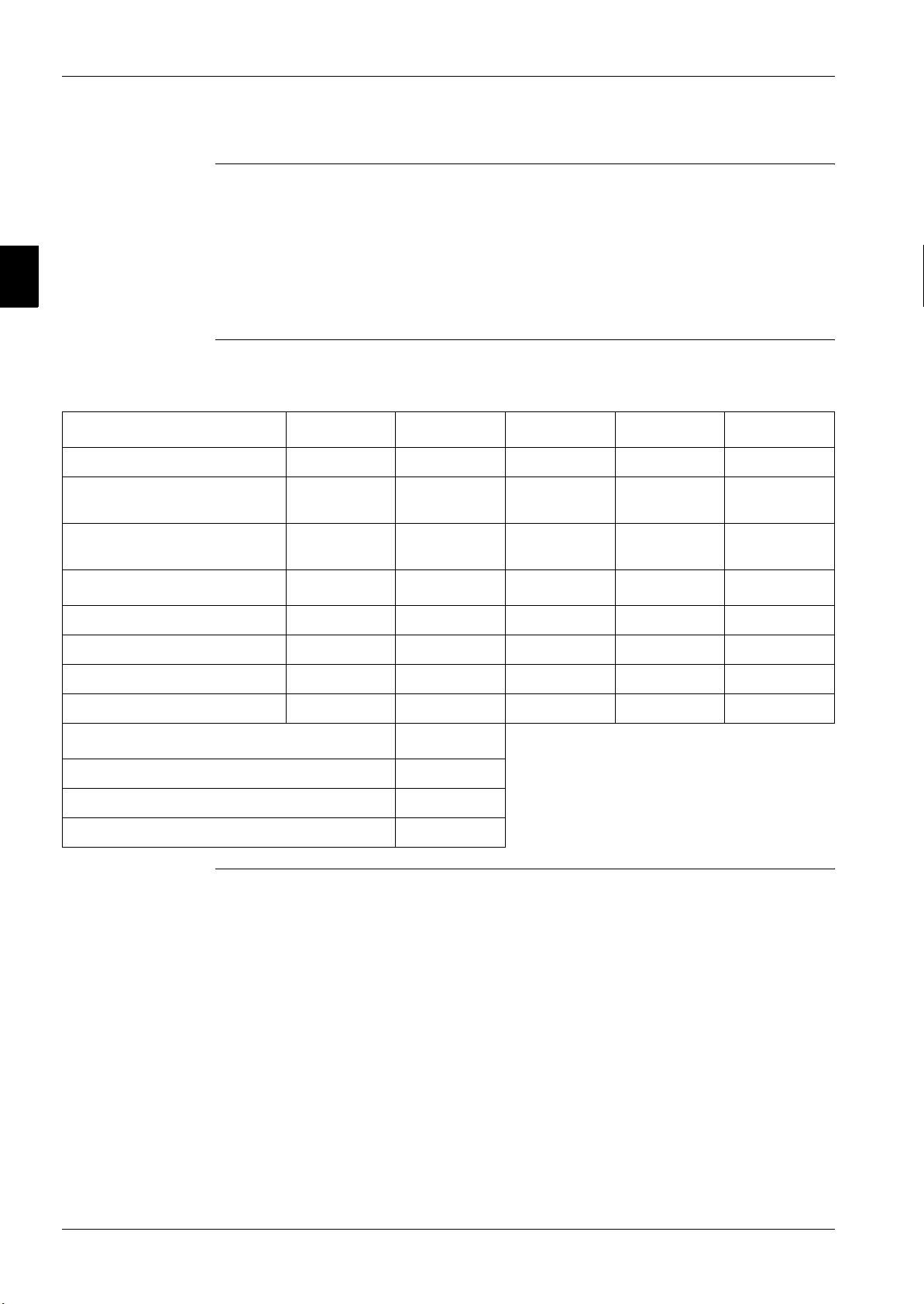
1.4.5 Addressing of pLAN
To get the correct functionality of the pLAN net system, it is necessary to address correctly all the
installed components. Each component has a series of microswitches that must be set as specified in
the table below.
1
pLAN component Microswitches
123456
Local DISPLAY OFF OFF OFF OFF ON OFF
Remote DISPLAY
(if available)
COMP. BOARD #1
COMP. BOARD #2
COMP. BOARD #3
COMP. BOARD #4
DRIVER EXV #1
DRIVER EXV #2
DRIVER EXV #3
ON OFF OFF OFF ON OFF
ON OFF OFF OFF OFF OFF
OFF ON OFF OFF OFF OFF
ON ON OFF OFF OFF OFF
OFF OFF ON OFF OFF OFF
ON OFF ON OFF OFF OFF
ON ON ON OFF OFF OFF
ON OFF OFF ON OFF OFF
2
3
4
5
DRIVER EXV #4
ON ON OFF ON OFF OFF
Part 2 – Functional Description 2–13
ESIE07-05 The Digital Controller
1.4.7 Display and Keypad
Introduction The display and the keypad are the main elements of interface between operator and unit. All the
operational conditions, the alarms and the setpoints can be monitored with this display and all the
values of setpoint can be modified through the keypad.
The keypad MicroTech II is constituted by 15 keys of access to the operational conditions of the unit
and to the functions of program. The information requested are shown on the backlight Display 4 lines
for 20 characters
Control panel
1
2
3
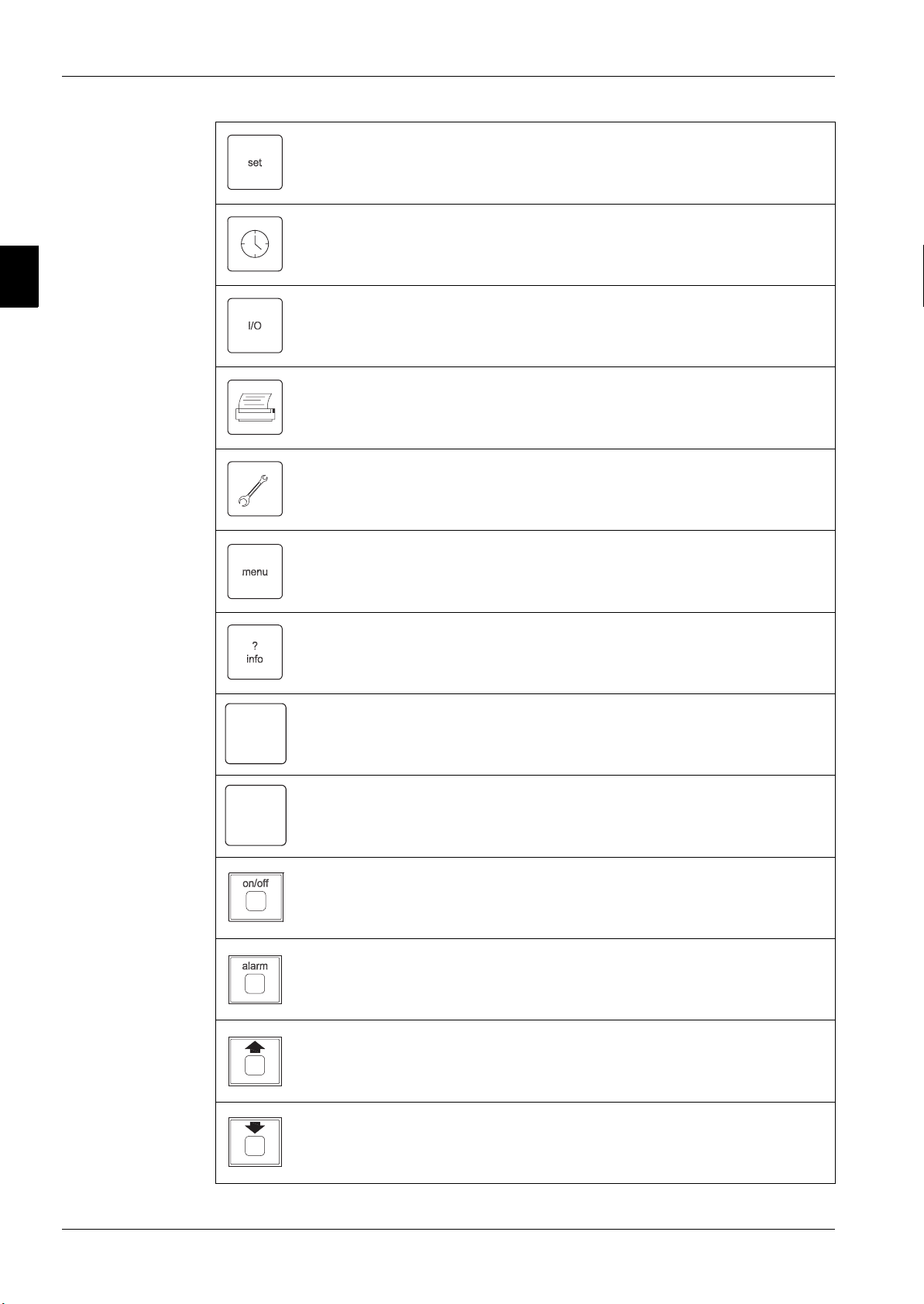
Keypad keys and
their functions
4
5
YB
By the user password it is po ssi ble to set the following parameters:
■ Setpoint limits
■ Setpoints reset values
■ Enable double setpoint
■ Regulation parameters
■ Startup and shutdown values
■ Soft load values
■ Hot chilled water start values
■ Ambient lockout values
■ Unit limiting
■ Fan silent mode values
■ Main pump timing
■ Digital and supervisor inputs enabling
■ Time scheduling
Part 2 – Functional Description 2–19
The Digital Controller ESIE07-05
1
2
3
4
It allows to adjust the setpoints within the limits previously set in prog.
Date and time setting.
Input/Output and corresponding circuit functions visualization.
Print (not available).
(=print)
By the Password it is possible to access the maintenance functions.
(=maint)
It allows to visualize the main menu.
5
Y
B
It allows the passage from one board to the other (visualizing parameters
of corresponding compressors).
It allows the changeover between chiller to heat pump (only if enabled).
It allows the changeover between heat pump to chiller (only if enabled).
Key On/Off unit.
It indicates the presence of possible anomalies and their causes.
It allows the passage to the previous display screen.
(=up)
It allows the passage to the next display screen.
(=down)
2–20 Part 2 – Functional Description

ESIE07-05 The Digital Controller
It enables the set values.
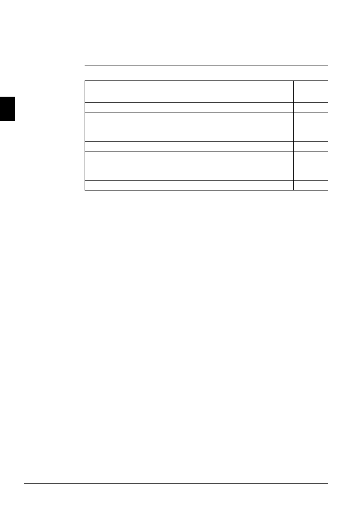
Screen categories Using the keypad you can access the different menus of the program. In particular there are 9 screen
categories, shortly introduced in the following table with the keys to use to access them and with the
type of operation they allow.
Category Description Keys Password
Main
User User parameter setting 0003
Setting Setpoint setting NO
Unit operating
parameters (view only)
NO
1
2
3
4
Input/Output
Manufacturer
Maintenance
Maint auxiliary
Alarm Alarms view NO
Alarm
history
Operating compressors
parameters (view only)
Manufacturer
parameters setup
Maintenance parameter
access
Auxiliary maintenance
parameter setting
Previous 10 recorded
alarms
NO
blue
+
+
NO
+
5
blueyellow
Note: The password remains valid for 10 minutes since last access.
Part 2 – Functional Description 2–21
1
2
3
The Digital Controller ESIE07-05
1.5 Controller Menu’s
Overview This chapter contains the following topics:
Topic See page
1.5.1–Main Menu 2–23
1.5.2–User Menu 2–26
1.5.3–Setting Menu 2–30
1.5.4–Input/Output Menu (I/O Menu) 2–31
1.5.5–Manufacturer Menu 2–33
1.5.6–Maintenance Menu 2–38
1.5.7–Service Menu 2–41
1.5.8–Alarm Menu 2–42
1.5.9–Buffer Alarm Menu 2–43
1.5.10–Alarm List 2–44
4
5
2–22 Part 2 – Functional Description

ESIE07-05 The Digital Controller
1.5.1 Main Menu
Introduction This menu shows only the output parameters throughout the screens listed below (the passage from
one to another is allowed by the arrow key).
Current date, time and weekday, setpoint origin and unit status in percent with the possibilities listed
below.
1
COMPRESSOR #1 STATUS
COMPRESSOR #2 STATUS
gg/mm/aa
Unit
Cooling
Stp Source:
Possible status :
■ Off Alarm : unit Off for alarm
■ Off Rem Comm : unit Off by remote communication (supervisor or BMS)
■ Off Time Schedule : unit Off by time schedule
■ Off Loc/Remote Sw : unit Off through switch
■ Off Keypad : unit Off through keypad (key on/off)
■ Off Amb. LockOut : unit Off by low ambient temperature (or tower return temperature)
■ Waiting flow : unit On waiting for evaporator water flow
Sat
status
staging
Local
Setpoint Source
hh:mm
xxx%
Unit Status
COMPRESSOR #3 STATUS
COMPRESSOR #4 STATUS
Compressor off
Compressor on
Compressor disabled or alarm
X
2
3
4
5
Setpoint source
Evaporator
outlet/inlet water
temperature
■ Waiting load : unit On without compressors in motion because not required by
load.
■ No comps available : unit On with no compressors available for automatic management
(compressor switch OFF or alarm or in manual mode )
■ Local
■ Double
■ Ret. Reset
This screen shows the Evaporator outlet/inlet water temperature (or common temperature for two
evaporators units)
Water Temperatures
ENT Evap
LVG Evap
First and second evaporator outlet temperature (two evaporators units)
=
=
xxx ˚C
xxx ˚C
Part 2 – Functional Description 2–23

The Digital Controller ESIE07-05
1
2
3
4
Condenser outlet
water temperature
Percent
compressor status
This screen shows the Condenser outlet water temperature (in heat pump or pursuit mode)
Water Temperatures
LVG Rec
This screen shows the Percent compressor status
Comp. #1
Status:
Possible status :
■ Off Alarm : Compressor OFF for alarm
■ Off Switch : Compressor OFF by local switch
■ Off Ready : Compressor OFF ready to start
■ Oil Heating : Compressor waiting for oil heating
■ Manual Off : Compressor disabled by keypad
=
Auto
xxx ˚C
xxx%
5
Suction and
discharge pressure
and saturated
temperature
Suction
temperature,
suction and
discharge
superheat,
expansion valve
position
■ Recycle Time : Compressor waiting for timing
■ Starting : Compressor starting
■ Pre Purge : Compressor unloading at starting
■ Auto xx% : Automatic control of compressor with percent load
■ Manual xx% : Manual control of compressor with percent load
■ Downl. : Compressor download before stop
■ Pumping down : Compressor pump down
This screen shows the Suction and discharge pressure and saturated temperature
Evap
Evap
Cond
Cond
This screen shows the Suction temperature, suction and discharge superheat, expansion valve
position
Suction
Suct
DelivSupHeat
Valve
Press
Temp
Press
Temp
Temp
SupHeat
Position
xx.x
xx.x
xx.x
xx.x
xx.x
xx.x
xx.x
barg
˚C
barg
˚C
˚C
˚C
˚C
xxxx
2–24 Part 2 – Functional Description
 Loading...