

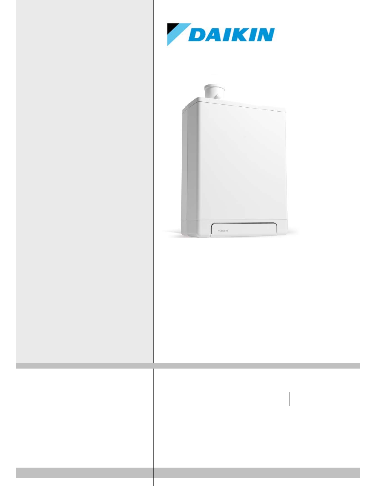
Daikin EKOMBG22AAV1, EKOMBG33AAV1, EKOMBG28AAV1, EKOMB22AAV1, EKOMB28AAV1 Installation Instructions And Operators Manual
...
Daikin Europe NV
EKOMBG22AAV1
EKOMBG28AAV1
EKOMBG33AAV1
Installation instructions English
Daikin Europe N.V.
CE - DECLARATION-OF-CONFORMITY
CE - KONFORMITÄTSERKLÄRUNG
CE - DECLARATION-DE-CONFORMITE
CE - CONFORMITEITSVERKLARING
CE - DECLARACION-DE-CONFORMIDAD
CE - DICHIARAZIONE-DI-CONFORMITA
CE - ∆HΛΩΣΗ ΣΥΜΜΟΡΦΩΣΗΣ
CE - DECLARAÇÃO-DE-CONFORMIDADE
CE - ЗАЯВЛЕНИЕ-О-СООТВЕТСТВИИ
CE - OVERENSSTEMMELSESERKLÆRING
CE - FÖRSÄKRAN-OM-ÖVERENSTÄMMELSE
CE - ERKLÆRING OM-SAMSVAR
CE - ILMOITUS-YHDENMUKAISUUDESTA
CE - PROHLÁŠENÍ-O-SHODĚ
CE - IZJAVA-O-USKLAĐENOSTI
CE - MEGFELELŐSÉGI-NYILATKOZAT
CE - DEKLARACJA-ZGODNOŚCI
CE - DECLARAŢIE-DE-CONFORMITATE
CE - IZJAVA O SKLADNOSTI
CE - VASTAVUSDEKLARATSIOON
CE - ДЕКЛАРАЦИЯ-ЗА-ϹЪОТВЕТСТВИЕ
CE - ATITIKTIES-DEKLARACIJA
CE - ATBILSTĪBAS-DEKLARĀCIJA
CE - VYHLÁSENIE-ZHODY
CE - UYGUNLUK-BEYANI
01
are in conformity with the following standard(s) or other normative document(s), provided that these are used in accordance with our
instructions:
02
der/den folgenden Norm(en) oder einem anderen Normdokument oder -dokumenten entspricht/entsprechen, unter der Voraussetzung,
daß sie gemäß unseren Anweisungen eingesetzt werden:03sont conformes à la/aux norme(s) ou autre(s) document(s) normatif(s), pour autant qu'ils soient utilisés conformément à nos instructions:04conform de volgende norm(en) of één of meer andere bindende documenten zijn, op voorwaarde dat ze worden gebruikt overeenkomstig
onze instructies:05están en conformidad con la(s) siguiente(s) norma(s) u otro(s) documento(s) normativo(s), siempre que sean utilizados de acuerdo con
nuestras instrucciones:
06
sono conformi al(i) seguente(i) standard(s) o altro(i) documento(i) a carattere normativo, a patto che vengano usati in conformità alle
nostre istruzioni:07είναι σύμφωνα με το(α) ακόλουθο(α) πρότυπο(α) ή άλλο έγγραφο(α) κανονισμών, υπό την προϋπόθεση ότι χρησιμοποιούνται σύμφωνα
με τις οδηγίες μας:
08
estão em conformidade com a(s) seguinte(s) norma(s) ou outro(s) documento(s) normativo(s), desde que estes sejam utilizados de
acordo com as nossas instruções:09соответствуют следующим стандартам или другим нормативным документам, при усл овии их использования согласно нашим
инструкциям:
10
overholder følgende standard(er) eller andet/andre retningsgivende dokument(er), forudsat at disse anvendes i henhold til vore
instrukser:11respektive utrustning är utförd i överensstämmelse med och följer följande standard(er) eller andra normgivande dokument, under
förutsättning att användning sker i överensstämmelse med våra instruktioner:12respektive utstyr er i overensstemmelse med følgende standard(er) eller andre normgivende dokument(er), under forutssetning av at
disse brukes i henhold til våre instrukser:13vastaavat seuraavien standardien ja muiden ohjeellisten dokumenttien vaatimuksia edellyttäen, että niitä käytetään ohjeidemme
mukaisesti:14za předpokladu, že jsou využívány v souladu s našimi pokyny, odpovídají následujícím normám nebo normativním dokumentům:15u skladu sa slijedećim standardom(ima) ili drugim normativnim dokumentom(ima), uz uvjet da se oni koriste u skladu s našim uputama:
16
megfelelnek az alábbi szabvány(ok)nak vagy egyéb irányadó dokumentum(ok)nak, ha azokat előírás szerint használják:17spełniają wymogi następujących norm i innych dokumentów normalizacyjnych, pod warunkiem że używane są zgodnie z naszymi
instrukcjami:
18
sunt în conformitate cu următorul (următoarele) standard(e) sau alt(e) document(e) normativ(e), cu condiţia ca acestea să fie utilizate în
conformitate cu instrucţiunile noastre:19skladni z naslednjimi standardi in drugimi normativi, pod pogojem, da se uporabljajo v skladu z našimi navodili:20on vastavuses järgmis(t)e standardi(te)ga või teiste normatiivsete dokumentidega, kui neid kasutatakse vastavalt meie juhenditele:21съответстват на следните стандарти или други нормативни документи, при условие, че се използват съгласно нашите
инструкции:
22
atitinka žemiau nurodytus standartus ir (arba) kitus norminius dokumentus su sąlyga, kad yra naudojami pagal mūsų nurodymus:23tad, ja lietoti atbilstoši ražotāja norādījumiem, atbilst sekojošiem standartiem un citiem normatīviem dokumentiem:24sú v zhode s nasledovnou(ými) normou(ami) alebo iným(i) normatívnym(i) dokumentom(ami), za predpokladu, že sa používajú v súlade
s našim návodom:25ürünün, talimatlarımıza göre kullanılması koşuluyla aşağıdaki standartlar ve norm belirten belgelerle uyumludur:
01
Directives, as amended.02Direktiven, gemäß Änderung.03Directives, telles que modifiées.04Richtlijnen, zoals geamendeerd.05Directivas, según lo enmendado.06Direttive, come da modifica.07Οδηγιών, όπως έχουν τροποποιηθεί.08Directivas, conforme alteração em.09Директив со всеми поправками.
10
Direktiver, med senere ændringer.11Direktiv, med företagna ändringar.12Direktiver, med foretatte endringer.13Direktiivejä, sellaisina kuin ne ovat muutettuina.14v platném znění.15Smjernice, kako je izmijenjeno.16irányelv(ek) és módosításaik rendelkezéseit
.
17
z późniejszymi poprawkami.18Directivelor, cu amendamentele respective.
19
Direktive z vsemi spremembami.20Direktiivid koos muudatustega.21Директиви, с техните изменения.22Direktyvose su papildymais.23Direktīvās un to papildinājumos.24Smernice, v platnom znení.25Deǧiştirilmiş halleriyle Yönetmelikler.
01
following the provisions of:02gemäß den Vorschriften der:03conformément aux stipulations des:04overeenkomstig de bepalingen van:05siguiendo las disposiciones de:06secondo le prescrizioni per:07με τήρηση των διατάξεων των:08de acordo com o previsto em:09в соответствии с положениями:
10
under iagttagelse af bestemmelserne i:11enligt villkoren i:12gitt i henhold til bestemmelsene i:13noudattaen määräyksiä:14za dodržení ustanovení předpisu:15prema odredbama:16követi a(z):17zgodnie z postanowieniami Dyrektyw:18în urma prevederilor:
19
ob upoštevanju določb:20vastavalt nõuetele:21следвайки клаузите на:22laikantis nuostatų, pateikiamų:23ievērojot prasības, kas noteiktas:24održiavajúc ustanovenia:25bunun koşullarına uygun olarak:
01 Note *
as set out in
<A>
and judged positively by
<B>
according to the
Certificate <C>
.
02 Hinweis *
wie in
<A>
aufgeführt und von
<B>
positiv beurteilt
gemäß
Zertifikat <C>
.
03 Remarque *
tel que défini dans
<A>
et évalué positivement par
<B>
conformément au
Certificat <C>
.
04 Bemerk *
zoals vermeld in
<A>
en positief beoordeeld door
<B>
overeenkomstig
Certificaat <C>
.
05 Nota *
como se establece en
<A>
y es valorado
positivamente por
<B>
de acuerdo con el
Certificado <C>
.
06 Nota *
delineato nel
<A>
e giudicato positivamente
da
<B>
secondo il
Certificato <C>
.
07 Σημείωση *
όπως καθορίζεται στο
<A>
και κρίνεται θετικά από
το
<B>
σύμφωνα με το
Πιστοποιητικό <C>
.
08 Nota *
tal como estabelecido em
<A>
e com o parecer
positivo de
<B>
de acordo com o
Certificado <C>
.
09 Примечание *
как указано в
<A>
и в соответствии
сположительным решением
<B>
согласно
Свидетельству <C>
.
10 Bemærk *
som anført i
<A>
og positivt vurderet af
<B>
i henhold til
Certifikat <C>
.
11 Information *
enligt
<A>
och godkänts av
<B>
enligt
Certifikatet <C>
.
12 Merk *
som det fremkommer i
<A>
og gjennom positiv
bedømmelse av
<B>
ifølge
Sertifikat <C>
.
13 Huom *
jotka on esitetty asiakirjassa
<A>
ja jotka
<B>
on
hyväksynyt
Sertifikaatin <C>
mukaisesti.
14 Poznámka *
jak bylo uvedeno v
<A>
a pozitivně zjištěno
<B>
v souladu s
osvědčením <C>
.
15 Napomena *
kako je izloženo u
<A>
i pozitivno ocijenjeno
od strane
<B>
prema
Certifikatu <C>
.
16 Megjegyzés *
a(z)
<A>
alapján, a(z)
<B>
igazolta a megfelelést,
a(z)
<C> tanúsítvány
szerint.
17 Uwaga *
zgodnie z dokumentacją
<A>
, pozytywną opinią
<B>
i
Świadectwem <C>
.
18 Notă *
aşa cum este stabilit în
<A>
şi apreciat pozitiv
de
<B>
în conformitate cu
Certificatul <C>
.
19 Opomba *
kot je določeno v
<A>
in odobreno s strani
<B>
v skladu s
certifikatom <C>
.
20 Märkus *
nagu on näidatud dokumendis
<A>
ja heaks
kiidetud
<B>
järgi vastavalt
sertifikaadile <C>
.
21 Забележка
* както е изложено в
<A>
и оценено положително
от
<B>
съгласно
Сертификата <C>
.
22 Pastaba *
kaip nustatyta
<A>
ir kaip teigiamai nuspręsta
<B>
pagal
Sertifikatą <C>
.
23 Piezīmes *
kā norādīts
<A>
un atbilstoši
<B>
pozitīvajam
vērtējumam saskaņā ar
sertifikātu <C>
.
24 Poznámka *
ako bolo uvedené v
<A>
a pozitívne zistené
<B>
v súlade s
osvedčením <C>
.
25 Not * <A>
’da belirtildiği gibi ve
<C> Sertifikasına
göre
<B>
tarafından olumlu olarak değerlendirildiği gibi.
<A> 177155_EMC2/03-2011
<B> KIWA (NB0063)
<C> -
01
a
declares under its sole responsibility that the equipment to which this declaration relates:
02
d
erklärt auf seine alleinige Verantwortung daß die Ausrüstung für die diese Erklärung bestimmt ist:
03
f
déclare sous sa seule responsabilité que l'équipement visé par la présente déclaration:
04
l
verklaart hierbij op eigen exclusieve verantwoordelijkheid dat de apparatuur waarop deze verklaring betrekking heeft:
05
e
declara bajo su única responsabilidad que el equipo al que hace referencia la declaración:
06
i
dichiara sotto la propria responsabilità che gli apparecchi a cui è riferita questa dichiarazione:
07
g
δηλώνει με αποκλειστική της ευθύνη ότι ο εξοπλισμός στον οποίο αναφέρεται η παρούσα δήλωση:
08
p
declara sob sua exclusiva responsabilidade que os equipamentos a que esta declaração se refere:
09
u
заявляет, исключительно под свою ответственность, что
оборудование,
к котором
у
относи тся настоящее заявление:
10
q
erklærer under eneansvarlig, at udstyret, som er omfattet af denne erklæring:
11
s
deklarerar i egenskap av huvudansvarig, att utrustningen som berörs av denna deklaration innebär att:
12
n
erklærer et fullstendig ansvar for at det utstyr som berøres av denne deklarasjon innebærer at:
13
j
ilmoittaa yksinomaan omalla vastuullaan, että tämän ilmoituksen tarkoittamat laitteet:
14
c
prohlašuje ve své plné odpovědnosti, že zařízení, k němuž se toto prohlášení vztahuje:
15
y
izjavljuje pod isključivo vlastitom odgovornošću da oprema na koju se ova izjava odnosi:
16
h
teljes felelőssége tudatában kijelenti, hogy a berendezések, melyekre e nyilatkozat vonatkozik:
17
m
deklaruje na własną i wyłączną odpowiedzialność, że urządzenia, których ta deklaracja dotyczy:
18
r
declară pe proprie răspundere că echipamentele la care se referă această declaraţie:
19
o
z vso odgovornostjo izjavlja, da je oprema naprav, na katero se izjava nanaša:
20
x
kinnitab oma täielikul vastutusel, et käesoleva deklaratsiooni alla kuuluv varustus:
21
b
декларира на своя отговорност, че оборудването, за коeто се отнася тази декларация:
22
t
visiška savo atsakomybe skelbia, kad įranga, kuriai taikoma ši deklaracija:
23
v
ar pilnu atbildību apliecina, ka tālāk aprakstītās iekārtas, uz kurām attiecas šī deklarācija:
24
k
vyhlasuje na vlastnú zodpovednosť, že zariadenie, na ktoré sa vzťahuje toto vyhlásenie:
25
w
tamamen kendi sorumluluǧunda olmak üzere bu bildirinin ilgili olduǧu donanımının aşaǧıdaki gibi olduǧunu beyan eder:
EN60335-2-40,
2P369568-1
Shigeki Morita
Director
Ostend, 3rd of March 2014
Low Voltage 2006/95/EC
Gas Appliances 2009/142/EC
Boiler Efficiency requirements 92/42/EEC
Electromagnetic Compatibility 2004/108/EC *
EKOMBG22AAV1*, EKOMBG28AAV1*, EKOMBG33AAV1*,
EKOMB22AAV1*, EKOMB28AAV1*, EKOMB33AAV1*,
* = , , 1, 2, 3, ..., 9

TABLE OF CONTENTS
1
2
3
4
5
6
7
8
9
10
11
© 2014 Daikin Europe NV
All rights reserved.
The information provided applies to the product in its standard version. Daikin Europe NV can therefore not be held liable for any damages arising from any
specifications of the product which deviate from the standard version. The available information has been compiled with the greatest possible care, but Daikin Europe
NV can not be held liable for any mistakes in the information, or for any consequences thereof. Daikin Europe NV cannot be held liable for any damage arising from
work carried out by third parties.
Subject to change.
Safety instructions 4
Unit description 5
2.1 General ............................................................................................................................................................................................ 5
2.2 Functioning ...................................................................................................................................................................................... 5
2.3 Operating modes ............................................................................................................................................................................. 5
2.4 PC Interface .................................................................................................................................................................................... 7
2.5 Test programs ................................................................................................................................................................................. 7
Main components 8
3.1 Accessories ..................................................................................................................................................................................... 9
Installation 10
4.1 Installation measurements ............................................................................................................................................................ 10
4.2 Installation space ........................................................................................................................................................................... 12
4.3 Assembly ....................................................................................................................................................................................... 13
Connecting 14
5.1 Connecting CH installation ............................................................................................................................................................ 15
5.2 Connecting DHW installation ......................................................................................................................................................... 17
5.3 Connecting electronically .............................................................................................................................................................. 18
5.4 Connect room thermostat .............................................................................................................................................................. 19
5.5 Connecting gas ............................................................................................................................................................................. 20
5.6 Flue gas output and air input ......................................................................................................................................................... 21
5.7 Outlet systems ............................................................................................................................................................................... 22
Commissioning the unit and the Installation 35
6.1 Filling and air purge of unit and installation ................................................................................................................................... 35
6.2 Commissioning the unit ................................................................................................................................................................. 36
6.3 Switching off the unit ..................................................................................................................................................................... 37
Setting and adjustment 38
7.1 Direct via operating panel .............................................................................................................................................................. 38
7.2 Parameter settings via the service code ....................................................................................................................................... 39
7.3 Setting maximum CH power .......................................................................................................................................................... 41
7.4 Set pump capacity ......................................................................................................................................................................... 41
7.5 Weather dependent regulation ...................................................................................................................................................... 41
7.6 Conversion to different type of gas................................................................................................................................................ 42
7.7 Gas/air regulation .......................................................................................................................................................................... 42
7.8 Setting gas/air regulation ............................................................................................................................................................... 43
Malfunctions 45
8.1 Show last malfunction ................................................................................................................................................................... 45
8.2 Malfunction codes ......................................................................................................................................................................... 45
Maintenance 49
Technical specifications 51
10.1 Electrical diagram .......................................................................................................................................................................... 52
10.2 NTC resistances ............................................................................................................................................................................ 53
Warranty conditions 54
Daikin Europe NV
3
These installation instructions
Description
To be referred to as
High Efficiency
HR
Daikin EKOMBG22AAV1, EKOMBG28AAV1 and
Unit
Unit with piping for central heating
CH installation
System with pipes for domestic hot water
DHW installation
CAUTION
IMPORTANT
will have a negative effect on the functioning of the
With these installation instructions, you can safely assemble, install and maintain the
unit. Carefully follow the instructions.
In case of any doubt, please contact the manufacturer.
Keep the installation instructions near the unit.
Abbreviations and terms used
EKOMBG33AAV1 wall-mounted gas boiler.
Symbols
The following symbols are used in this manual:
Procedures which - if they are not carried out with the
necessary care - may cause damage to the product, the
surroundings, the environment or injury.
Procedures and/or instructions which, if they are not
followed,
unit.
Service and technical support for the installer
For information about specific settings, installation, maintenance and repair work, as
an installer, please contact your local Daikin dealer.
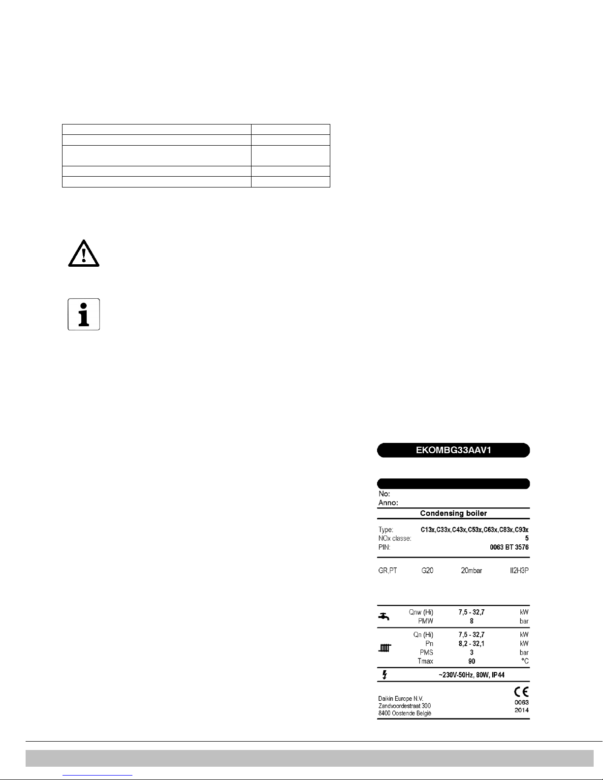
Identification of the product
You will find the unit details on the type plate on the bottom of the unit.
A. Unit type
B. Bar code with article number and serial number
C. Options
1 SAFETY INSTRUCTIONS
The manufacturer Daikin accepts no liability for damage or injury caused by the
failure to (strictly) observe the safety instructions, or negligence during the
installation of the Daikin EKOMBG*AAV1 wall-mounted gas boiler and any
associated accessories.
This device is not intended for use by people (including children) with reduced
physical, sensory or mental abilities, or lack of experience and knowledge, unless
they are given supervision or instructions on the use of the device by a person who
is responsible for their safety.
The instructions are stated separately for the various disciplines.
The entire installation must meet the applicable local technical and (safety)
instructions, for the gas installation, the electrical installation, smoke extraction
installation, drinking water installation, and central heating installation.
Daikin Europe NV 4
2 UNIT DESCRIPTION
2.1 General
The Daikin EKOMBG*AAV1 wall-mounted gas boiler is a closed unit. The unit is
intended to provide heat to the water of a CH-installation and the domestic hot water
installation.
The air supply and the combustion gas outlet of the EKOMBG*AAV1 can be connected
to the unit by two separate pipes, or by a concentric connection. The unit was tested in
combination with the combi feedthrough, but the unit may also be connected to combi
feedthroughs which meet the universal test standards for combi feedthroughs.
The unit can be connected to an assembly bracket if required, a frame with top
connection, and various installation sets. These are provided separately.
The Daikin EKOMBG*AAV1 wall-mounted gas boilers have the CE quality mark,
electrical protection class IP44.
It is possible to use the unit solely for warm water, or solely for heating. The system
which is not in use, does not need to be connected (see par. 7.2).
The unit is delivered for natural gas (G25) as a standard. On request, the unit can also
be provided for propane (G31).
2.2 Functioning
The Daikin EKOMBG*AAV1 wall-mounted gas boiler is a modulating high-efficiency
boiler. This means that the power is modulated to suit the required heat demand. In the
aluminum heat exchanger two separate copper circuits are integrated.
The separate circuits for CH and warm water allow the heating and warm water supply
to function independently. The hot water supply takes precedence over the heating.
Both cannot work at the same time.
The unit is fitted with an electronic boiler controller machine, which operates the fan
and the modulating pump at every heat requirement of the heating or the warm water
supply, opens the gas valve, ignites the boiler controller, and continuously monitors
and regulates the flame, depending on the requested power. The pump is only
operated during a heat request from the heating, depending on the requested power.
2.3 Operating modes
The operating mode of the unit is indicated by means of a code on the service display
of the operating panel.
-
Off
The unit is not in operation, but is connected to the electricity supply. No response is
given to requests for domestic hot water or CH water. The unit frost protection is
active. This means that the pump will start running and the exchanger will be heated
up if the temperature of the water in the system drops too far.
If the frost protection intervenes, the code
The pressure in the CH installation can also be read from the temperature display in
this operating mode (in bar).
Standby
The LED at the key is lit and possibly one of the LEDs of the tap comfort function.
The unit is ready to respond to a request for CH or tap water.
0
Post-running CH
After the end of the CH-operation, the pump will post-run. The post-pumping time is set
to the value in par. 7.2 in its factory settings. This setting can be changed. In addition
to this, the pump will run automatically 1 time per 24 hours, for 10 seconds, in order to
prevent it from getting stuck. This automatic switching on of the pump takes place at
the time of the last heating request. In order to change this, the room thermostat needs
to be set higher for a moment, at the required time of day.
1
Requested temperature reached
The boiler controller may temporarily block the heat request. The boiler controller will
then be stopped. The block occurs because the required temperature has been
reached. When the temperature has sufficiently decreased, the block will be lifted.
Daikin Europe NV
7
will be displayed (heating up exchanger).
5
2
Selftest
Once every 24 hours, the boiler controller tests the connected sensors. During the
test, the controller will not carry out any other tasks.
3
Ventilating
When the unit is started, the fan is first brought up to its correct start rpm. When the
start rpm is reached, the boiler controller will be ignited. Code 3 is also visible when
there is post-fanning after the boiler controller is stopped.
4
Igniting
When the fan has reached the start rpm, the boiler controller will be ignited by means
of electrical sparks. During the ignition, code
does not ignite, a new attempt will be made after approximately 15 seconds. If after 4
ignition attempts, the boiler controller has still not been ignited, the controller will go
into down-time.
5
CH-operation
An on/off thermostat, an OpenTherm thermostat, an outdoor sensor or a combination
thereof can be connected to the controller (see par. 10.1)
When there is a heat request from a thermostat, after the fan has started running
(code 3 ), the ignition will take place (code
(code 5 ).
During CH operation, the rpm of the fan and therefore the power of the unit can be
adjusted so the temperature of the CH water to the required CH supply temperature
can be controlled. If an on/off thermostat has been connected, this will be the CH
supply temperature set on the display. In case of an OpenTherm or wireless
thermostat, the required CH supply temperature is determined by the thermostat. In
case of an outdoor sensor, the required CH supply temperature is determined by the
fuel line programmed in the boiler controller. For the last two situations, the
temperature set on the display is the maximum.
During CH operation, the requested CH supply temperature will be displayed on the
operating panel.
The CH supply temperature can be set between 30 and 90°C (see par. 7.1). Caution:
for a low temperature system, a lower maximum setting may be required than the
standard setting of 80°C.
You can press the service button during CH operation to read the actual CH supply
temperature.
4
is displayed. If the boiler controller
4
) followed by the CH operating mode
If the tap comfort function is switched on (see code
of less than 40 degrees will be generated.
6
Domestic hot water operation
The hot water supply takes precedence over the heating. If the flow switch senses a
request for more than 2 l/min of domestic hot water, any CH requests will be
interrupted. After the fan has switched on (code
(code 4 ), the controller will switch to domestic water operation (code
domestic hot water operation, the rpm of the fan, and therefore the power of the unit,
is controlled by the controller on the basis of the set tap water temperature.
The control system ensures the tap water temperature is correct. The water
temperature can be set between 40°C and 65°C (see par. 7.1).
The set tap water temperature is displayed on the operation panel. The standard
setting is 60°C.
You can press the service button during tap water operation to read the actual tap
water temperature.
7
Heating up unit
In order to provide a fast supply of domestic hot water, a so-called tap comfort
function has been installed in the unit. This function keeps the heat exchanger at the
right temperature (it can be set, see par. 7.2). The tap comfort function has the
following settings:
•
On: ( LED on) The tap comfort function of the unit is continuously switched on.
Daikin Europe NV 6
7
), an OpenTherm heat request
3
) and there has been an ignition
6
). During
The unit always immediately provides warm water.
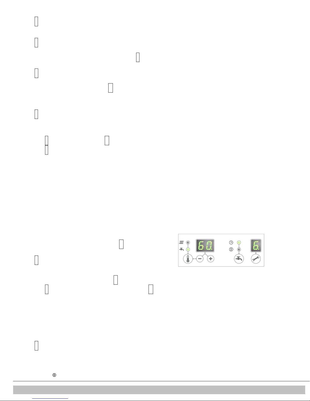
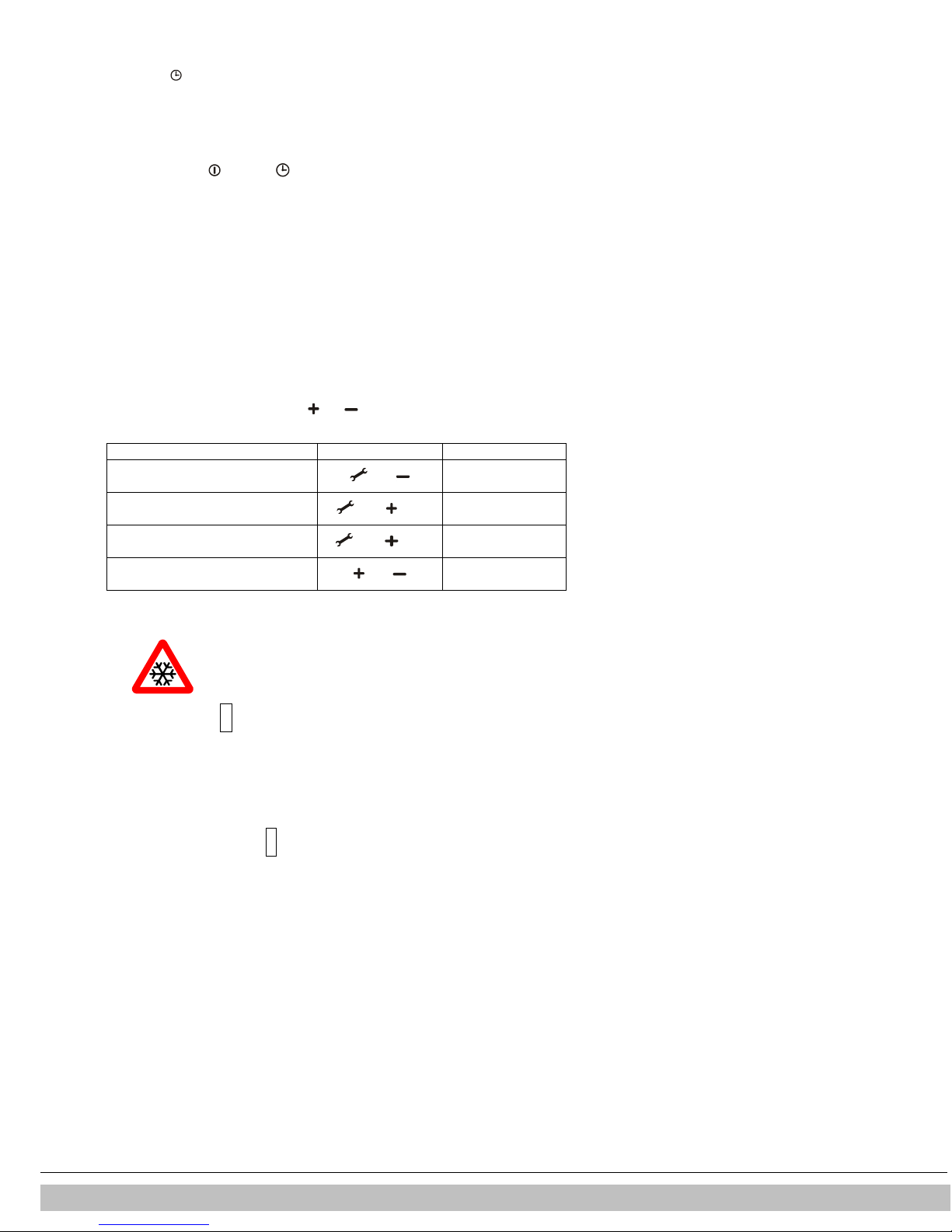
Description of program
Button combination
Display reading
Burner on with minimum
DHW
Burner on with set maximum CH
Burner on with maximum
DHW power
Current operation
The unit is fitted with frost protection in order to prevent it from
ntervenes, code
frost thermostat on the return pipe.
•
Eco: ( LED on) The tap comfort function of the unit is self-learning. The unit will
adjust to the usage pattern of the domestic hot water. This means the heat
exchanger will not be kept warm during the night or during longer absences.
•
Off: (Both LEDs off) The heat exchanger is not kept warm which means the supply of
domestic hot water takes a bit of time. If there is no need for fast delivery of domestic
hot water, the tap comfort function can be switched off.
In the settings "on" and "eco" , the unit meets the requirements of the Gaskeur
[Gas Inspection] CW standards.
2.4 PC Interface
The boiler controller is provided with an interface for a PC. A PC can communicate with
the CH boiler by means of a special dongle, and the associated software. This facility
enables you to follow the behavior of the boiler controller, the unit and the heat
installation over a long period.
2.5 Test programs
There is an option in the boiler controller, to bring the unit into a test status.
Activating a test program, will switch on the unit with a set fan rotations per minute,
without the control functions intervening.
The safety functions do remain active.
The test program is ended by pressing and simultaneously.
Test programs
capacity (see parameter d par. 7.2)
power (see parameter 3 par. 7.2)
(see parameter 3 par. 7.2)
Switching off test program and
and
and (1x)
and (2x)
"L"
"h"
"H"
situation
2.5.1 Frost protection
•
freezing. If the temperature of the heat exchanger drops too low,
the pump will start running until the temperature of the heat
exchanger is sufficiently high. If the frost protection i
7‘
will be displayed (heating up exchanger).
•
If the installation (or a part thereof) can freeze, the coldest place
should be fitted with an (external)
This must be connected in accordance with the electrical diagram
(see par. 10.1).
Note
When the unit is switched off (
remain active, however a heat request from an (external) frost thermostat will be ignored.
-
on the service display), the unit frost protection will
Daikin Europe NV
7
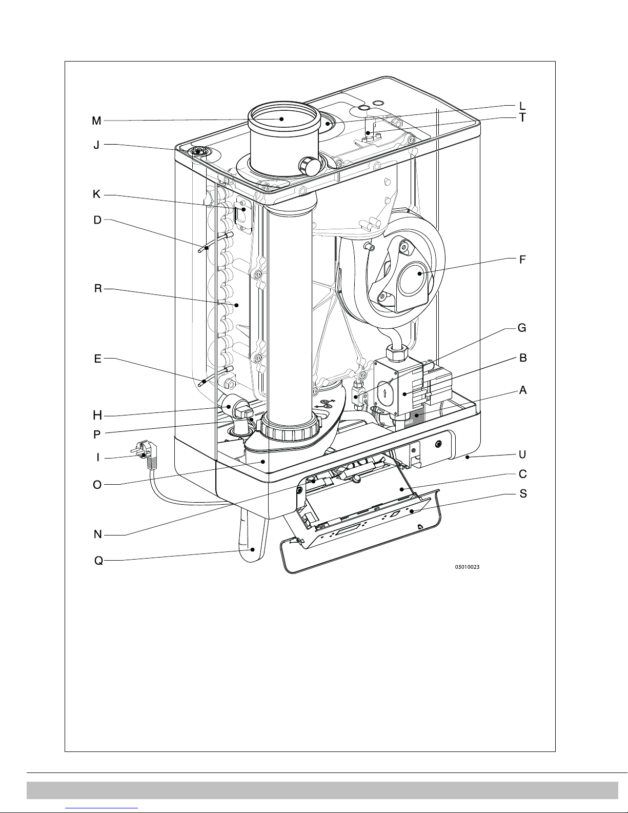
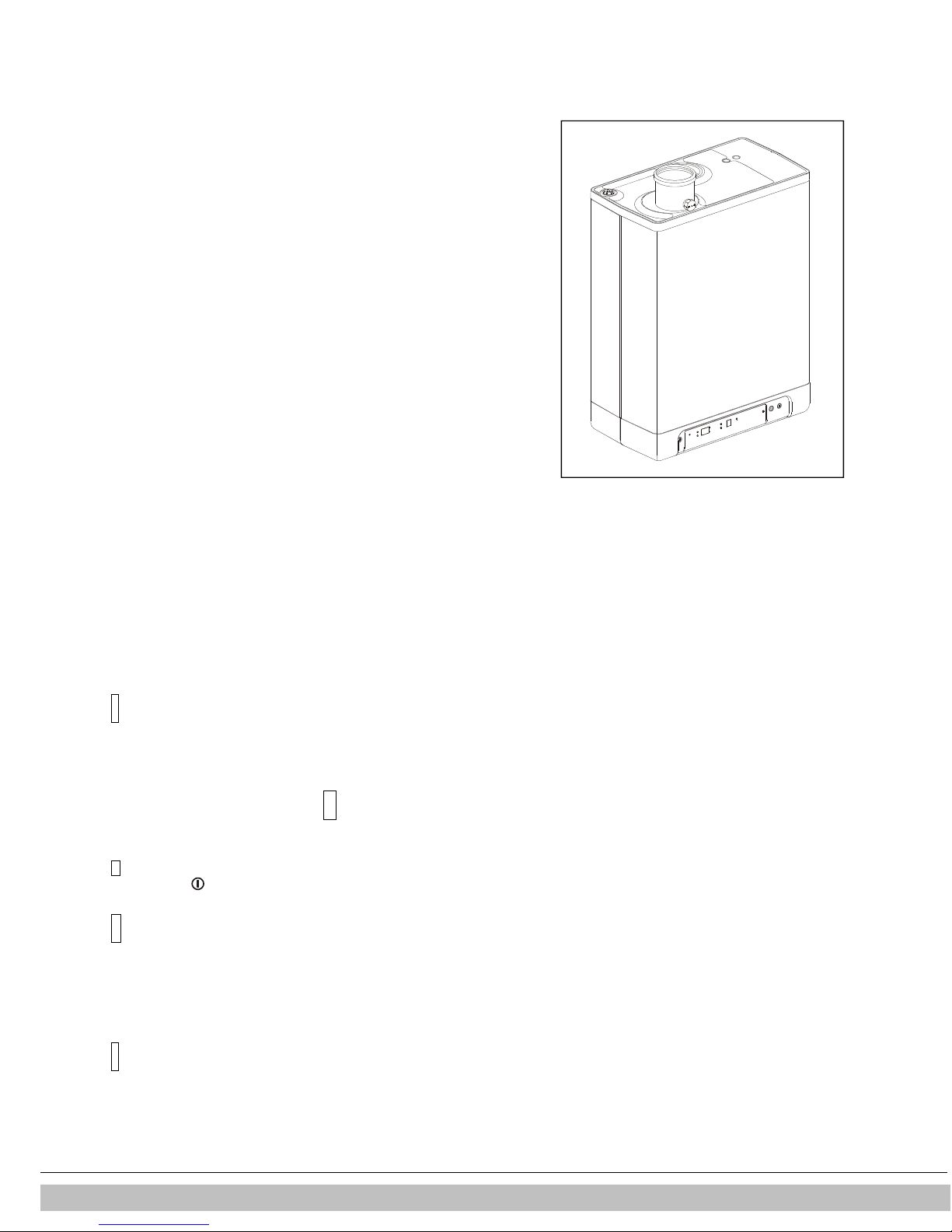
3 MAIN COMPONENTS
A. CH
pump L. Air supply (only when using twin pipe flue system)
B. Gas
valve M. Flue gas/air inlet concentric adapter
C. Burner
controller
(incl. operating panel)
N.
Connection block / terminal strip X4
D. Sensor S1 (flow)
O.
Condensate drain pan
E. Sensor S2 (return)
P.
Domestic hot water
sensor S3
F. Fan Q. Siphon
G. Flow sensor
R.
Heat exchanger
H. Pressure sensor central heating
S.
Operating panel and display
I. Connection wire 230 V ~ with earthed plug
T.
Ionization / ignition pen
J. Manual air bleed
U.
Position
of data plate
K. Sight glass
Daikin Europe NV 8
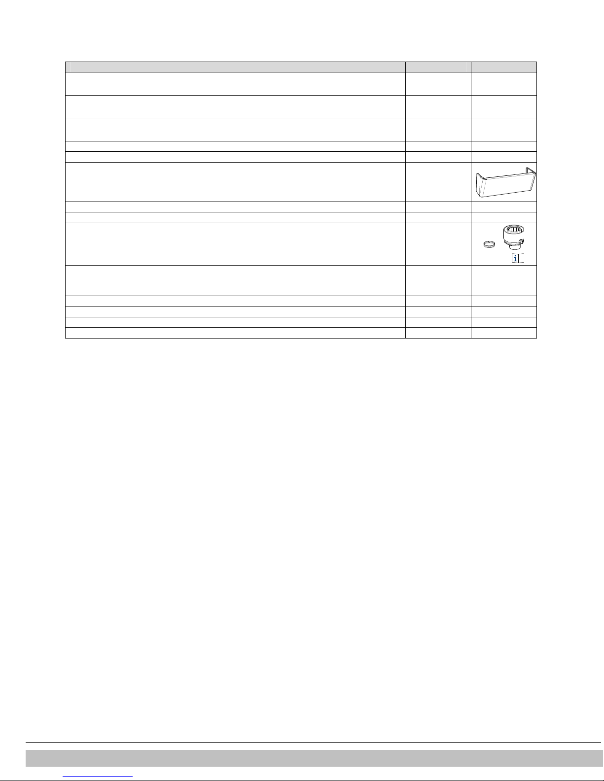
3.1 Accessories
Description
Article numbers
B-pack EKFJS*AA
EKFJS*AA
B-pack middle
EKFJM*AA
B-pack large
EKFJL*AA
Valve kit
EKVK4AA
Cover
plate EKOMBG*AAV1
EKCP1AA
O
utdoor
sensor
EKOSK1AA
3-way valve set
EK3WV1AA
Flue gas adapter Concentric
Ø
80x125
EKHY090717
Flue gas adapter Parallel 80 mm
EKHY090707
Propane set
*KOMBG22AAV1
EKPS075877
Propane set *KOMBG28AAV1
EKPS075867
Propane set *KOMBG33AAV1
EKHY075787
Daikin Europe NV
9
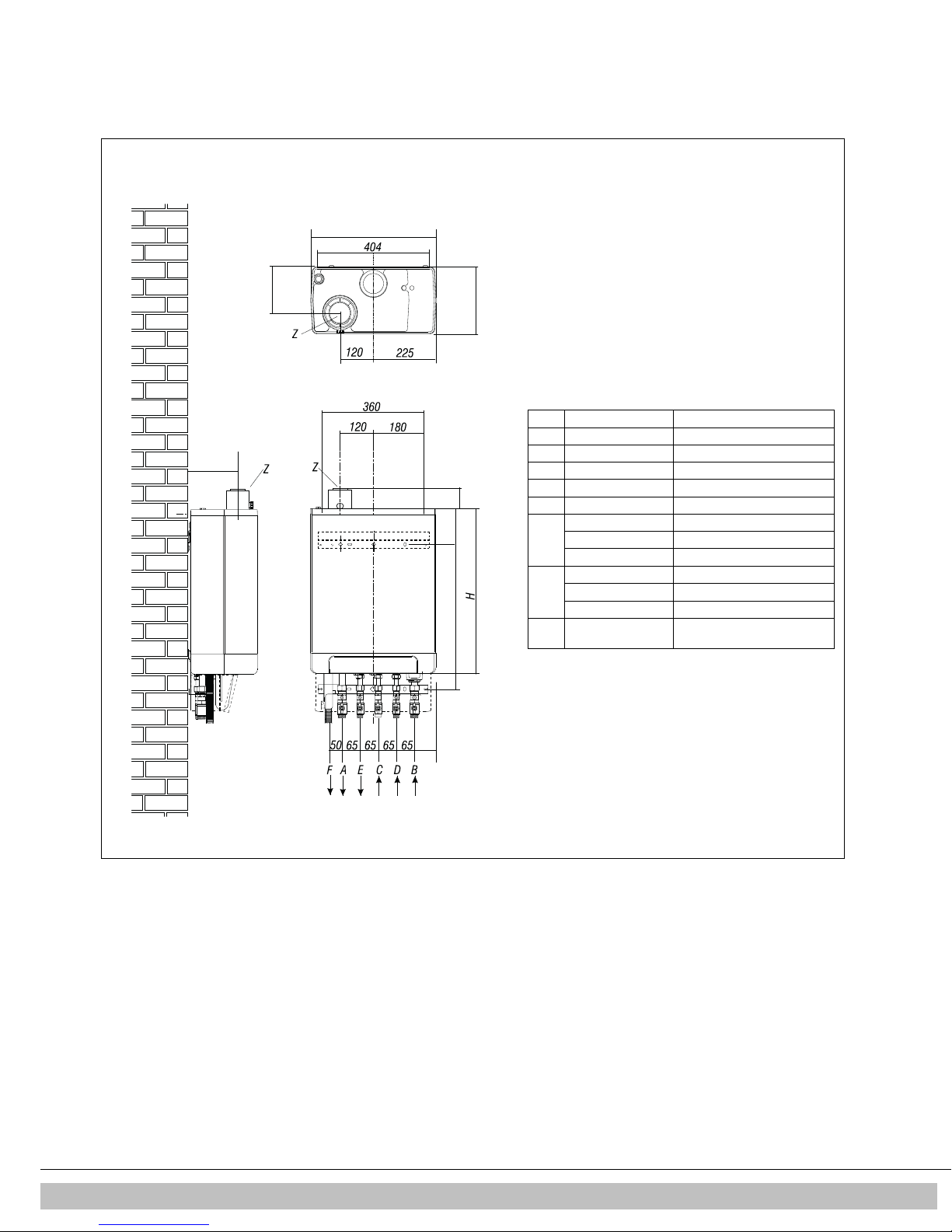
4 INSTALLATION
A = Supply CH
G ¾” (ext)
B = Return CH
G ¾” (ext)
C = Gas G ½” (int)
D = Tap water cold
G ½” (ext)
E = Tap water warm
G ½” (ext)
F = Condense outlet
Ø dn25 (flexible)
h= 517mm
EKOMBG22AAV1
577mm
EKOMBG28AAV1
637mm
EKOMBG33AAV1
H= 590mm
EKOMBG22AAV1
650mm
EKOMBG28AAV1
710mm
EKOMBG33AAV1
Z = Flue gas outlet/air
Ø60/100 (concentric)
020601002
161
161
450
240
135
h
77
75
4.1 Installation measurements
Boiler mounted directly to the wall
Connections:
inlet
Daikin Europe NV 10
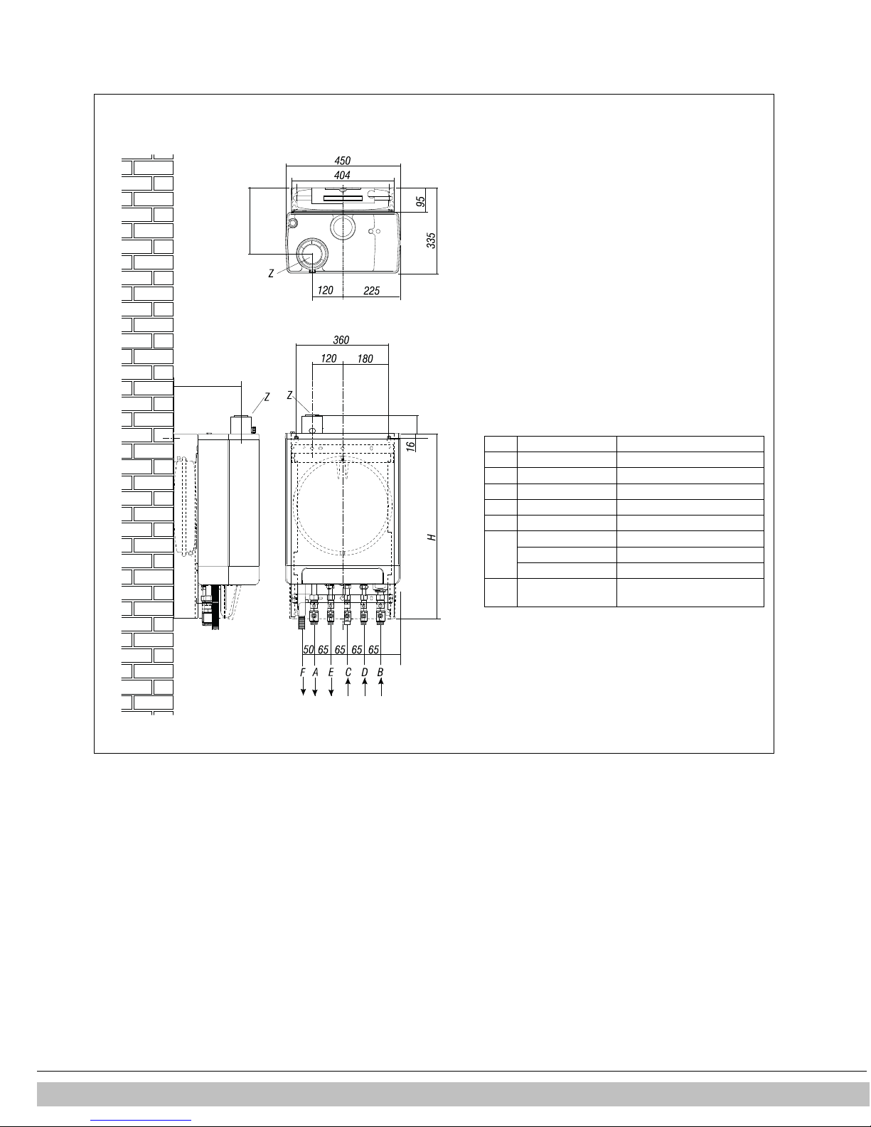
A = Supply CH
G ¾” (ext)
B = Return CH
G ¾” (ext)
C = Gas G ½” (int)
D = Tap water cold
G ½” (ext)
E = Tap water warm
G ½” (ext)
F = Condense outlet
Ø dn25 (flexible)
H= 770mm
EKOMBG22AAV1
830mm
EKOMBG28AAV1
890mm
EKOMBG33AAV1
Z = Flue gas outlet/air
Ø60/100 (concentric)
020601001
265
265
77
75
Unit connected to B-pack:
Connections:
inlet
Daikin Europe NV
11
Daikin Europe NV 12
4.2 Installation spac e
The unit must be installed against a wall with sufficient load bearing capacity.
In case of light wall constructions, there is a risk of resonance noises.
Within 1 meter of the unit, there must be a earthed wall plug.
In order to prevent the condense outlet from freezing, the unit must be installed in a
frost-free room. Preferably ensure there is a space of at least 2 cm next to the boiler.
No free space is required due to danger of singeing.
IMPORTANT
The unit must not be installed in a space where work is carried out
with aggressive or corrosive gases such as hairspray.
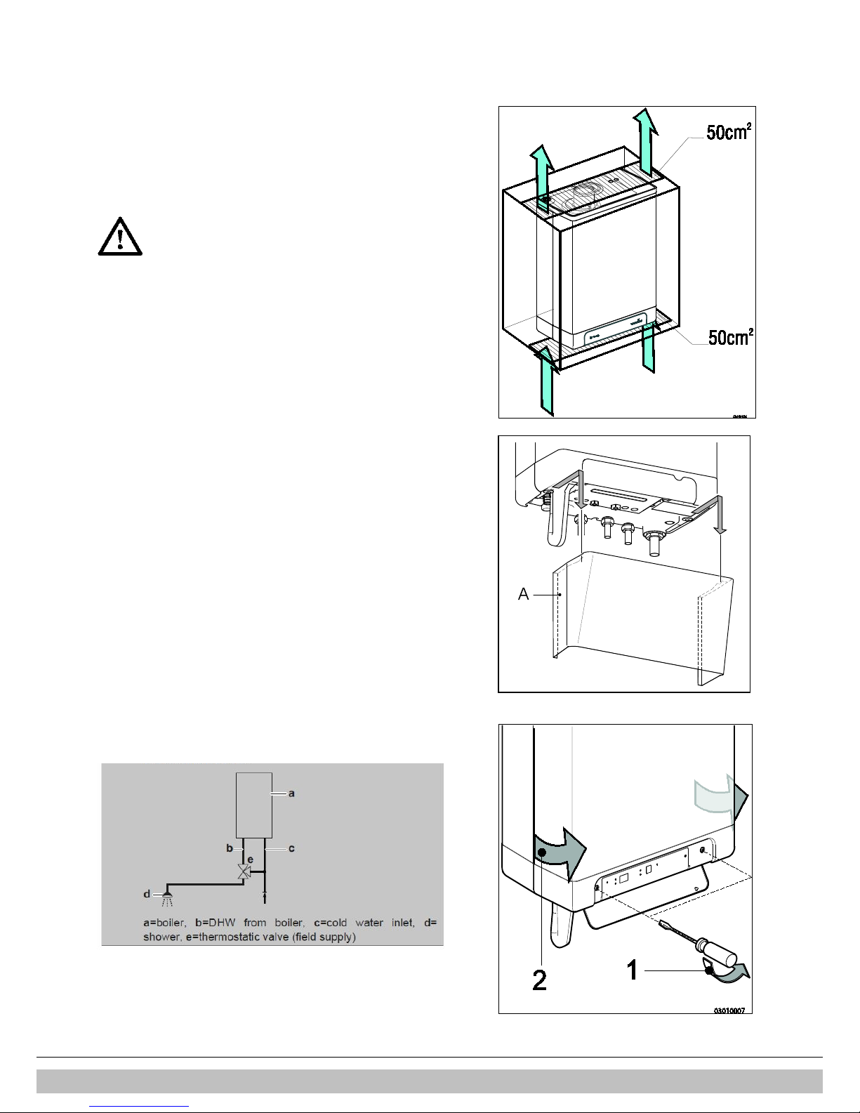
4.2.1 Installing in kitchen cabinet
The unit can be placed between two kitchen cabinets, or inside a kitchen cabinet.
Make sure there is sufficient ventilation at the bottom and the top.
If the unit is installed inside a cabinet, ventilation openings of at least 50 cm
2
are
required.
4.2.2 Removing cover plate and front panel
For various activities on the unit, the cover plate and front panel have to be removed
from the unit, if they were installed. Do this as follows:
• If you are using the cover plate (A), remove it to the front.
• Unscrew both screws (1) behind the display window.
• Pull the bottom of the front panel (2) forwards.
Danger: risk of burning
In case of high leaving water set ponts for space heating (eighter a high fixed set point
or a high weather-dependent set point at low ambient temperatures), the heat
exchanger of the boiler can be very hot, for example 70°C.
Beware that in case of a tapping demand, the water can initially have a higher water
temperature than requested.
In this case, it is recommended to install a thermostatic valve to prevent scalding.
This can be done according to the schematics below.
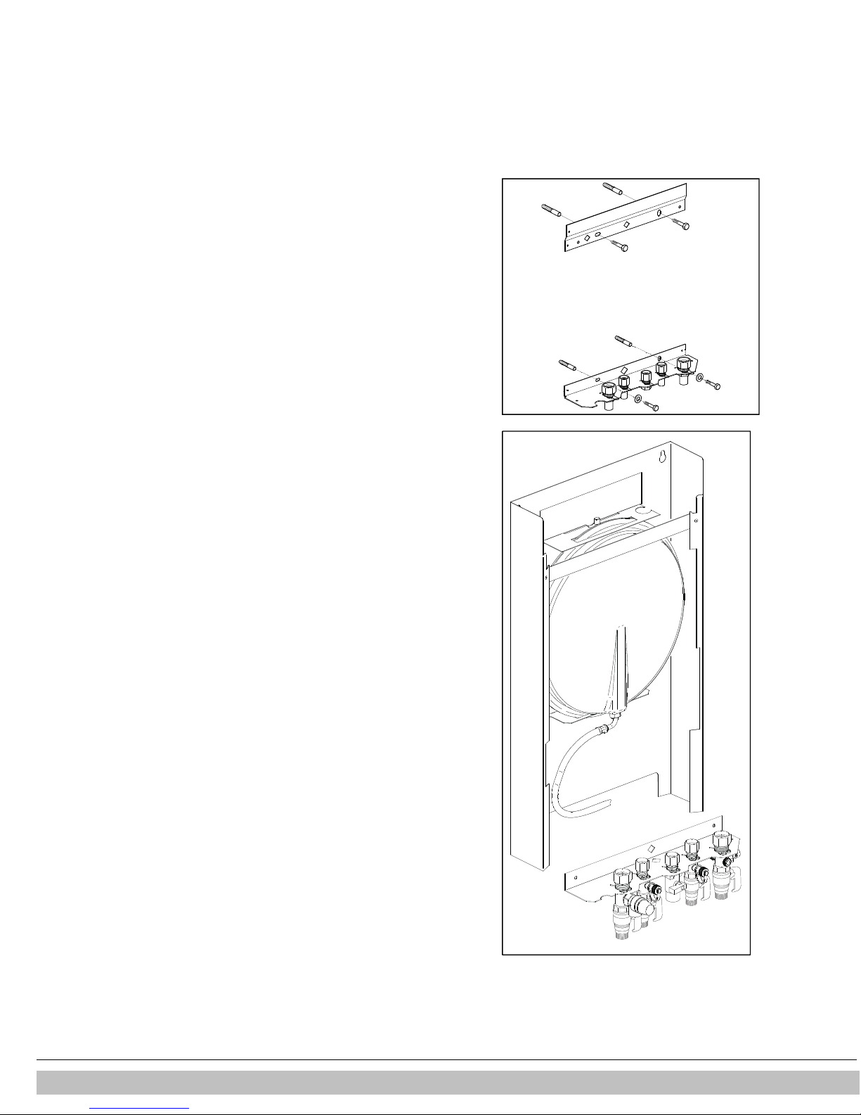
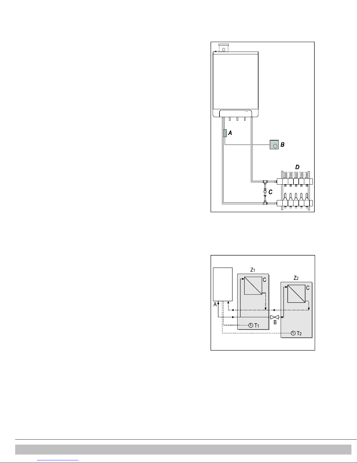
4.3 Assembly
020601020
The boiler can be hung to the wall using :
•
the wall suspension strip and a the connection kit EKVK4AA
•
a B-pack including an expension vessel and a connection kit.
4.3.1 Assembling suspension strip and assembly bracket
• Make sure the construction of the wall is suitable for hanging the boiler.
• Drill the holes for the suspension strip and the connection kit in the wall
using the template delivered with the boiler.
• Mount the suspension strip and the assembly bracket horizontally on the
wall, using the associated attachment materials.
• Place the filling loop on the connections of the return and cold water nipple
following the connection kit installation instruction
• The boiler can now be placed on the suspension strip simultaniously sliding
the pipes of the boiler into the valves in the assembly bracket.
4.3.2 Assembling bottom connection set
• Make sure the construction of the wall is suitable for hanging the boiler and
B-pack.
• Drill the holes for the B-pack kit in the wall using the template delivered
with the boiler.
• Mount the B-pack on the wall using the associated attachment materials.
• Place the assembly bracket in the frame as described in the manual
inclued in the B-pack.
• Connect the flexible hose on the expension vessel and the conenction on
the return valve. Make sure the seal rings are placed !
• Place the filling loop on the connections of the return and cold water nipple
following the connection kit installation instruction
• The boiler can now be placed on B-pack simultaniously sliding the pipes of
the boiler into the valves in the assembly bracket
Daikin Europe NV
13
4.3.3 Assembling the unit
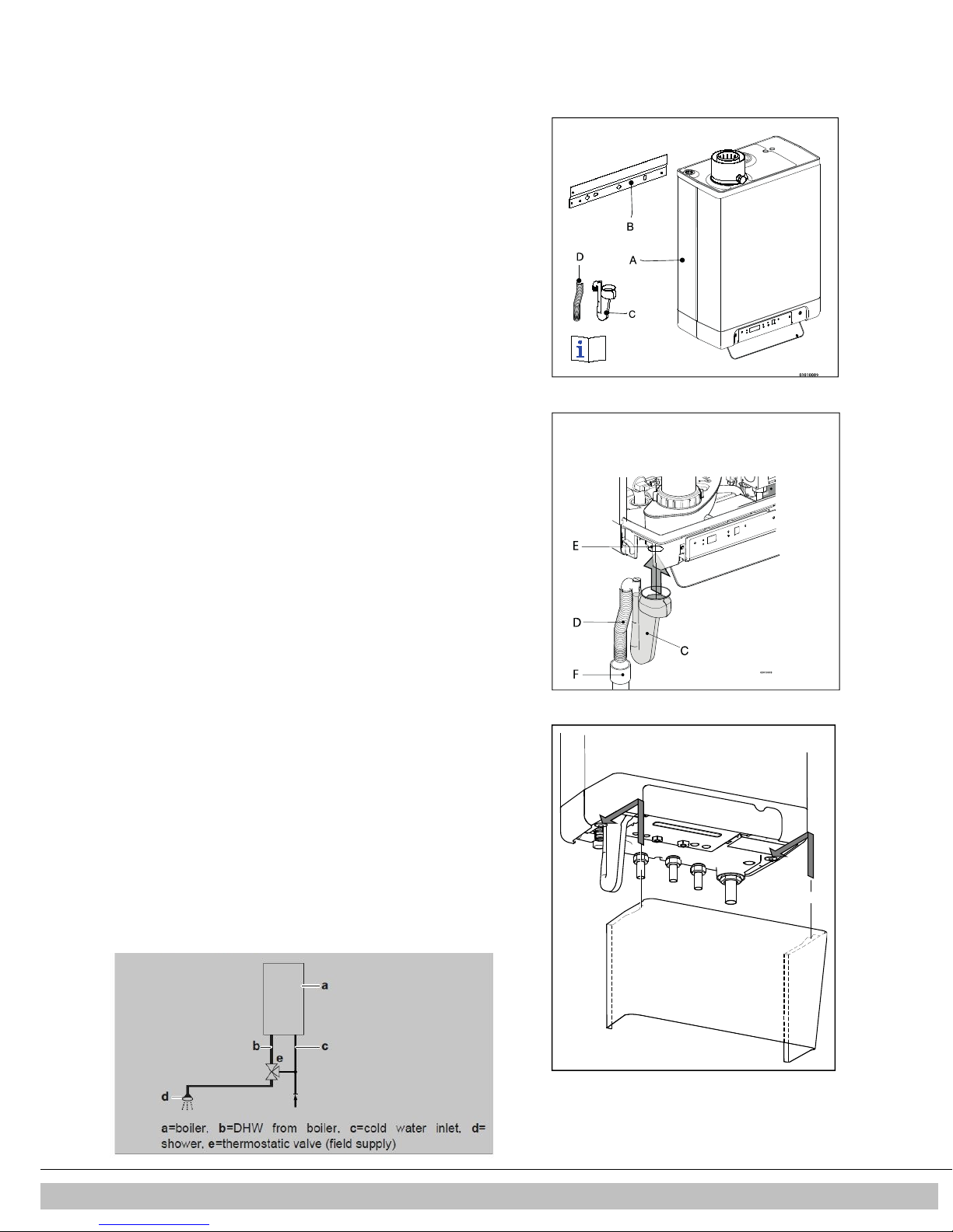
1. Unpack the unit.
2. Check the content of the packaging, which consists of:
• Unit (A)
• Suspension strip (B)
• Siphon (C)
• Flexible tube (D)
• Installation instructions
• Operating instructions
• Warranty card
3. Check the unit for any damage: immediately report damages to the supplier.
4. Install the suspension strip.
5. Check whether the compression rings are positioned straight in the couplings of
the assembly bracket.
6. Position the unit: slide it from top to bottom over the suspension strip (B). Make
sure the pipes slide into the compression fittings simultaneously.
7. Tighten the compression fittings onto the assembly bracket.
The nipples and pipes must not rotate with it!
8. Open the display valve and loosen the two screws on the left and right of the
display, and remove the front panel.
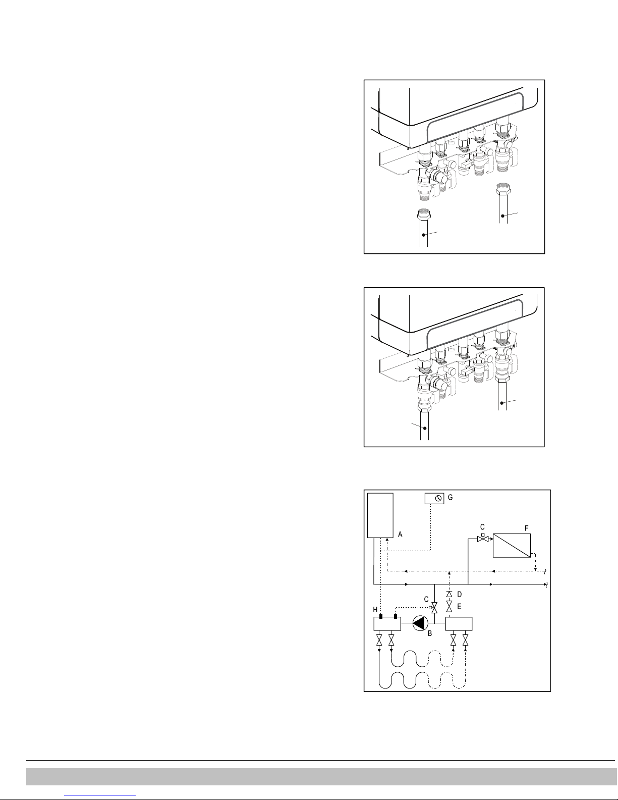
9. Assemble the flexible tube (D) onto the outlet of the siphon.
10. Fill the siphon with water, and slide it as far as possible on top of the condense
output connector (E) under the unit.
11. Seal flexible tube (D) of the siphon, if possible together with the overflow pipe of
the inlet combination and the overflow valve, to the sewage via open connection
(F).
12. Assemble the air supply and the burning gas outlet (see par. 5.6).
13. Assemble the cover and tighten the two screws to the left and the right of the
display, and close the display cover.
4.3.4 Apply cover plate (optional)
Suspend the converted top edge of the cover plate from the washers underneath the
bottom of the unit, and slide the cover plate as far back as possible.
Danger: risk of burning
In case of high leaving water set ponts for space heating (eighter a high fixed set point
or a high weather-dependent set point at low ambient temperatures), the heat
exchanger of the boiler can be very hot, for example 70°C.
Beware that in case of a tapping demand, the water can initially have a higher water
temperature than requested.
In this case, it is recommended to install a thermostatic valve to prevent scalding.
This can be done according to the schematics below.
5
Daikin Europe NV 14
CONNECTING
A
B
020601013
B
A
020601014
5.1 Connecting CH installation
1. Rinse the CH installation carefully.
2. Fit the supply pipe (A) and return pipe (B) to the connection set.
3. All pipes must be assembled with no electrical current, in order to prevent shocks
from the pipes.
4. Existing connections may not be rotated, in order to prevent leakages.
The CH installation must be fitted with:
•
A filling/draining tap (A) in the return pipe, immediately underneath the unit.
•
A draining tap at the lowest point of the installation.
•
An overflow valve (B) of 3 bar in the input pipe at a distance of no more than 500
mm from the unit.
Between the unit and the overflow valve there may be no valve or constriction.
•
An expansion vessel in the return pipe (in the B-pack or in the installation).
•
A check valve, if there are pipes running up, within close distance of the unit. This
prevents a thermosiphon effect from occurring during tap water operation (a non
spring-operated return valve, must be assembled vertically).
5.1.1 Thermostatic radiator taps
If all radiators are fitted with thermostatic or cable radiator taps, a minimum water
circulation must be safeguarded. See par. 7.3.
5.1.2 Underfloor heating
Underfloor heating with pump
If an underfloor heating system is not hydraulically neutral, the underfloor heating
pump may generate unwanted circulation over the CH boiler. For a good functioning of
the domestic hot water provision, unwanted circulation over the CH boiler must be
prevented.
Connect an underfloor heating system indirectly hydraulically neutrally or provide the
CH installation with a two-way valve set 230 V ~ (E). If the underfloor heating pump
absorbs heat via the return of the boiler, unwanted circulation can be prevented by
means of a check valve (D).
Make sure there is a minimal water circulation. See par. 7.3.
Connection diagram underfloor heating
A. CH boiler G. Space/clock thermostat
B. CH pump H. Maximum thermostat
C. Thermostatic control valve
D. Spring-operated check valve
E. Electrical valve 230 V ~
F. Radiators
Daikin Europe NV
15
Underfloor heating without pump
Connect the underfloor heating system (D) and set the maximum CH supply temperature of the CH boiler to the design condition. Fit a clamp
thermostat (A) onto the supply tube underneath the CH boiler. The clamp thermostat
with blind cap must be set to a maximum supply temperature of 55°C.
Fit the on/off room thermostat (B) and connect in a series with the clamp thermostat.
The boiler must be connected to X4 - 6/7.
In this situation, the pump in the boiler is used to bridge the loss of pressure of the
underfloor heating system. Using the loss of pressure graph par. 7.4, the maximum loss
of pressure of the underfloor heating system can be determined.
Make sure there is a minimal water circulation. See par. 7.3.
In case of an underfloor heating system without pump, we recommend changing the
following parameter settings:
par. o from 0 to 3.
par. P from 5 to 2.
Parameter 3 must also be set to its minimum level, or the
Transmission loss of the property, see par. 7.3.
5.1.3 Dividing CH installation in groups in case of additional heat
sources
Operating principle
If the room thermostat switches off the boiler because another heat source, the other
rooms may cool down.
This can be resolved by splitting the CH installation into two groups. The group with the
external heat source (Z2) can be shut off from the main circuit by means of an electrical
shut-off valve. Both groups are fitted with their own room thermostat.
Please note: This "external heat source" regulation may only be applied if no extra
external boiler has to be heated up (installation type 1).
Installation instructions
5. Install the valve in accordance with the connection diagram.
6. Connect the room thermostat of group 1 to op X4 – 6/7.
7. Connect the room thermostat of group 2 to op X4 – 11/12.
8. Change parameter A (see Parameter settings via the service code par. 7.2).
Please note: The room thermostat in group
thermostat in group 2 may be an OpenTherm thermostat or an on/off thermostat.
Connection diagram "external heat source" regulation
A. CH boiler
B. Electrical shut-off valve 230 V ~
C. Radiators
T1. Room thermostat group 1
T2. Room thermostat group 2
Z1. Group 1
Z2. Group 2
1 MUST
be an on/off thermostat. The room
Daikin Europe NV 16
5.2 Connecting DHW installation
D
C
020601015
1. Rinse the installation carefully.
2. If required, assemble an inlet combination.
3. Assemble the cold (D) and warm water pipe (D) to the connection set.
Comments
•
If the unit is only used for warm water supply, the heating function can be switched
off using the service code on the operating panel. The CH installation does not need
to be connected or filled.
•
If the unit is switched off during winter, and is disconnected from the electricity
supply, the sanitary water must be drained in order to prevent freezing. To do so,
disconnect the tap water connections straight underneath the unit.
In case of old installations or domestic hot water circuits which can contain small particles, install
a filter in the domestic hot water circuit.
This pollution could cause a fault during domestic hot water operation.
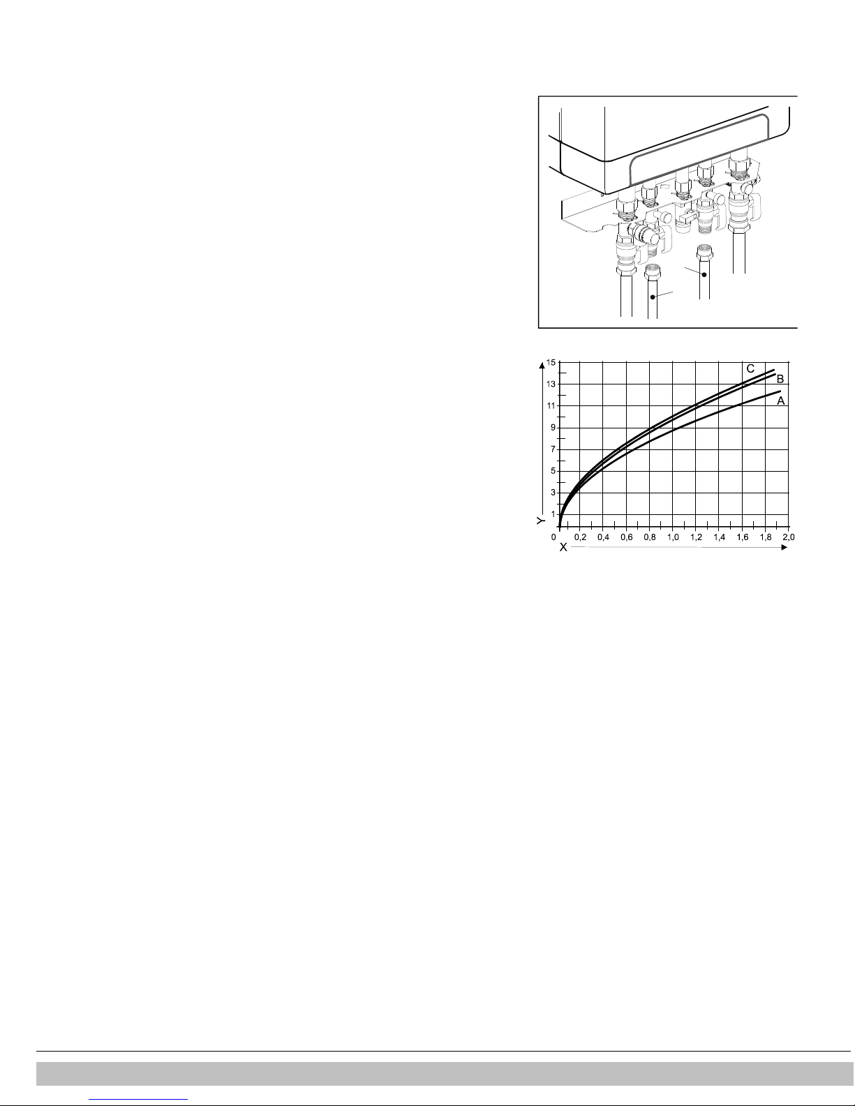
Resistance graph tap circuit unit
A. EKOMBG22AAV1
B. EKOMBG28AAV1
C. EKOMBG33AAV1
X. Water pipe pressure (Bar)
Y. Flow rate (L/min, tolerance ± 10%)
Daikin Europe NV
17
 Loading...