


Design guide
Modbus Interface DIII
EKMBDXB7V1

4P642495-1– 2020.10 Page 1 of 52
Design guide Modbus Interface DIII
EKMBDXB7V1
Table of Contents
Safety Precautions .............................................................................................................................................. 3
1. Introduction .................................................................................................................................................... 3
1.1 System layout ........................................................................................................................................... 3
1.2 Limitations ................................................................................................................................................ 4
1.3 Specifications ............................................................................................................................................ 4
1.3.1 Dimensions and field wiring .............................................................................................................. 5
1.3.2 Wiring diagram .................................................................................................................................. 6
1.3.3 LED meaning ...................................................................................................................................... 6
1.3.4 Termination resistance (SS switches) ................................................................................................ 6
1.3.5 Push buttons ...................................................................................................................................... 7
1.3.6 Dipswitch meaning ............................................................................................................................ 7
1.4 Overview of compatible Daikin units ranges with DIII connection ........................................................... 8
1.5 Overview of compatibilty with other DIII centralised control equipment................................................ 8
2. Modbus communication ............................................................................................................................... 10
2.1 Modbus Interface DIII settings................................................................................................................ 10
2.2 Communication format .......................................................................................................................... 11
2.2.1 Function format ............................................................................................................................... 11
2.2.2 Character format ............................................................................................................................. 14
2.2.3 Silent internal time .......................................................................................................................... 14
2.2.5 Response time ................................................................................................................................. 14
2.3 Communication procedure ..................................................................................................................... 15
2.3.1 System initialisation ......................................................................................................................... 15
2.3.2 Monitor and operate units from the BMS ....................................................................................... 16
2.3.3 Other DIII devices exist in the same system .................................................................................... 20
3. Modbus registers .......................................................................................................................................... 21
3.1. Input registers ........................................................................................................................................ 21
3.2 Holding registers ..................................................................................................................................... 32
4. Software of Modbus Interface DIII ............................................................................................................... 40
4.1 Software releases ................................................................................................................................... 40
4.2 Software update with Updater ............................................................................................................... 40
4.2.1 Updater ............................................................................................................................................ 40
4.2.2 Method 1) Update with the PC USB cable EKPCCAB*. .................................................................... 41
4.2.3 Method 2) Update with a USB/RS485 converter. ............................................................................ 43
5. Modbus Interface DIII test operation ........................................................................................................... 45

4P642495-1– 2020.10 Page 2 of 52
5.1 Introduction ............................................................................................................................................ 45
5.2 Outline of system .................................................................................................................................... 45
5.3 Test Operation Procedure ...................................................................................................................... 46
5.3.1 Prepare register groups ................................................................................................................... 46
5.3.2 Start reading registers groups ......................................................................................................... 49
5.3.3 Set a holding register ....................................................................................................................... 50
6. Troubleshooting ............................................................................................................................................ 51
7. Revision of the document ............................................................................................................................. 52

4P642495-1– 2020.10 Page 3 of 52
Safety Precautions
Before performing design, construction, or maintenance thoroughly, read the “Safety Precautions” in the
installation manual provided with the product.
1. Introduction
A Building Manangement System (BMS) can control Daikin units through the Modbus protocol by using the
Modbus Interface DIII EKMBDXB7V1.
Glossary:
- BMS: Building Management System
- DIII unit: Unit with DIII communication connected to the Modbus Interface DIII.
- DIII device: A centralised device from Daikin with DIII communication (e.g. iTM, …)
- Indoor unit: As the main target is to monitor and control VRV connected indoor units, the DIII units are
referred to as indoor units. For some systems the connected DIII units are in reality outdoor units (e.g. Applied
units)
1.1 System layout
Typical setup (e.g. VRV)
DIII address (Group NO) needs to be set on an individual indoor unit or group by the connected userinterface.
Functions of each Indoor unit in a range for each register:
Example:
Register address
DIII address functions
31001 – 31003
1-00
31004 - 31006
1-01
…
…
BMS
Outdoor
Outdoor
Indoor
Indoor
Indoor
1-00
1-01
1-02
DIII address
Indoor
Indoor
Indoor
1-03
1-04
1-05
DIII address
Modbus Interface DIII
RS485 Modbus protocol
2 wire, max wire length 500m
DIII indoor
connection
DIII outdoor
connection
One Modbus slave
address
(e.g. 1)

4P642495-1– 2020.10 Page 4 of 52
1.2 Limitations
The number of control commands per indoor unit is limited to 7000 per year.
If the BMS controls the units by using an automatic control program, please make sure it doesn’t exceed this
limitation.
1.3 Specifications
Daikin equipment connection
DIII net (F1F2)
maximum 64 indoor units (groups) and maximum 10 outdoors (addr 1-00 till 4-15)
BMS equipment protocol
Modbus RS485 (2 wire, max 500m)
Installation place
Indoor installation
Operation condition
Temp range 0 till 60°C
Dimensions
379 x 87 x 124 mm
Mass (Weight)
2,1 kg
Power supply
220 – 240 VAC 50 Hz
Software
The Modbus Interface DIII software can be updated with the Daikin Updater PC software
Refer to chapter “4.2 Software update with Updater” for details.
Installation manual
Provided with the option
Design guide
Latest version available on:
http://www.daikineurope.com/support-and-manuals/product-information
4P642495-1– 2020.10 Page 5 of 52
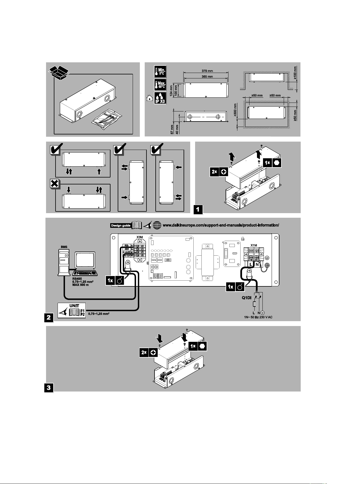
1.3.1 Dimensions and field wiring
Refer to installation manual

4P642495-1– 2020.10 Page 6 of 52
1.3.2 Wiring diagram
1.3.3 LED meaning
During normal operation (application is running):
H1P: DIII communication (sent)
H2P: DIII communication (receive)
H3P: RS485 communication (sent)
H4P: RS485 communication (receive)
H5P H6P H7P: no meaning
HAP: blinking at 400ms = application is running
During uploading of new software (firmware is running)
H1P till H7P: Progress indication (0 till 100%)
HAP: blinking at 200ms = firmware is running.
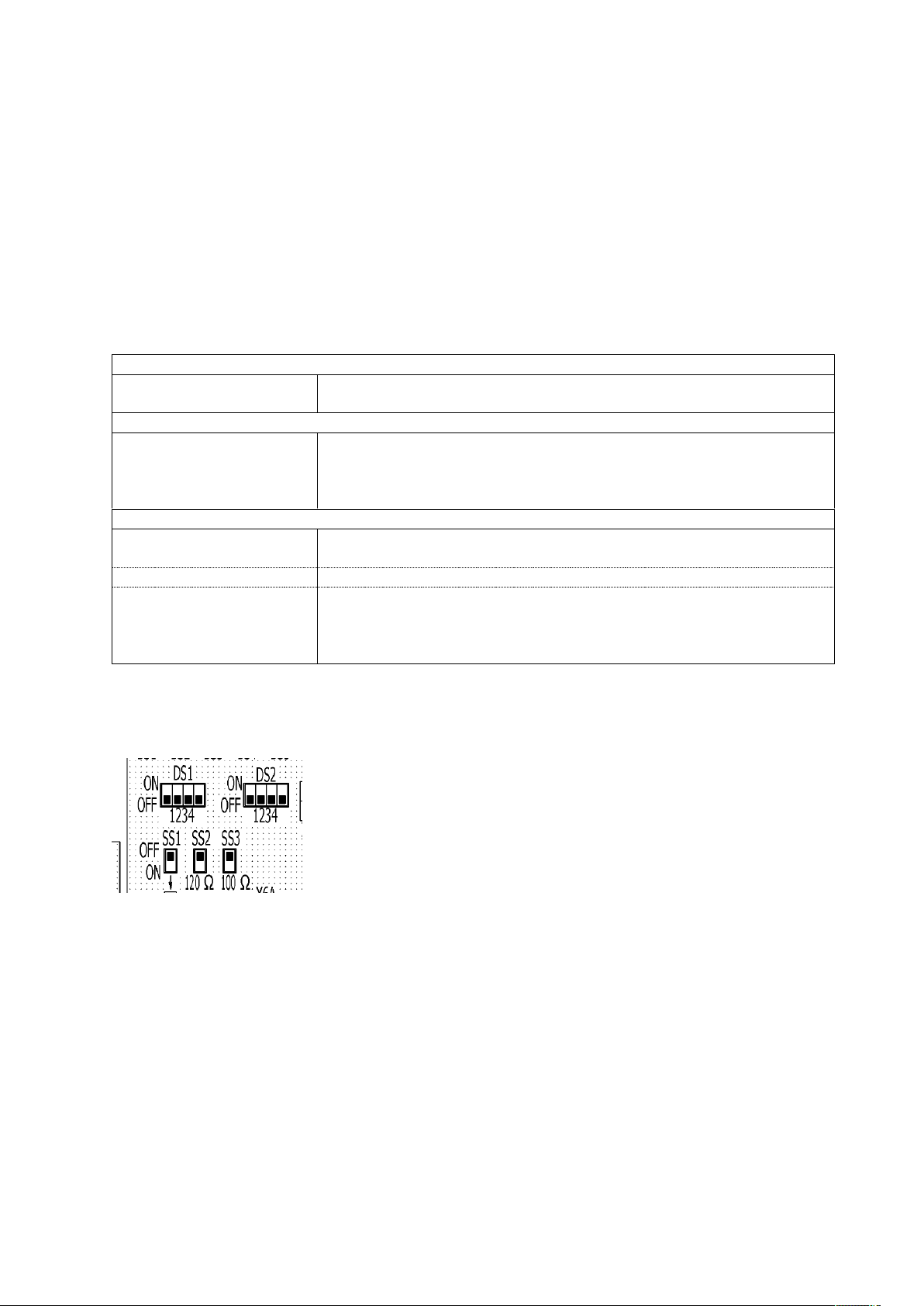
1.3.4 Termination resistance (SS switches)
By factory default the termination resistance is 0 Ohm (SS2=Off & SS3 =Off)
SS2 On = 120 Ohm
SS3 On = 100 Ohm
(SS2 = On & SS3 = On, not allowed)
Please slide the SS2 or SS3 to the ON position to set required termination resistance value of the RS485 line.
Remark: SS1: not used.
4P642495-1– 2020.10 Page 7 of 52
1.3.5 Push buttons
BS1 till BS5 have no meaning
1.3.6 Dipswitch meaning
Attention: Dipswitch on/off status is detected during power on of the PCB only. A power reset is needed after
setting the switches.
Dipswitch DS1 & DS2 setting:
RS485 Modbus communication speed
DS1 pin 2:Off
DS1 pin 2:On
9600 bps
19200 bps
Modbus communication parity / stop bit
DS1 pin 3:Off 4:Off
DS1 pin 3:Off 4: On
DS1 pin 3:On 4:Off
DS1 pin 3:On 4:On
Even 1 stop bit
Odd 1 stop bit
None 2 stop bit
None 1 stop bit
Modbus address setting
DS2 pin 1/2/3/4
When Modbus address is set (eg 1..15), then modbus RS485 communication is
enabled.
Off/Off/Off/Off
No Modbus address is set, meaning no modbus RS485 communication
Off/Off/Off/On
Off/Off/On/Off
…
On/On/On/On
Address 1
Address 2
Address 15
Attention:
During software upload with updater PC program via RS485 port a specific dipswitch setting is required.
Refer to chapter “4.2.3 Method 2) Update with a USB/RS485 converter.” for details.
Remark: DS1 – pin 1: not used.

4P642495-1– 2020.10 Page 8 of 52
1.4 Overview of compatible Daikin units ranges with DIII connection
For compatibility with a specific model, please check the manual of the corresponding model. Updates of the
software will be available on the Business Portal (maintenance by Service)).
Product overview:
• SKY (F1,F2)
• VRV (F1,F2)
• RA (via KRP928)
• VAM / VKM
• EKVDX
• VRV Hydro Box
• Air curtains
• ERQ-Control box (connection to 3rd party AHU)
• Heating
• Applied
1.5 Overview of compatibilty with other DIII centralised control equipment
Intelligent Touch Manager
Interface for use in LonWorks®
Interface for use in BACnet®
Intelligent Touch Controller
Intelligent Tablet Controller
Residential central remote controller
Central Remote controller
Unified ON/OFF controller
Schedule timer
(*1)
DCM601A51
DMS504B51 DMS502B51
DCS601C51
DCC601A51
DCS303A51
DCS302CA61
DCS301BA61
DST301BA61
DIII Modbus
interface
EKMBDXB7V1
OK
NG
NG
OK
NG
NG
OK
OK
NG
(*1): The schedule timer should be used in combination with the central remote controller or unified ON/OFF
controller
• If using in combination with centralized control equipment, the relation between both
central remote controllers is last command priority.

4P642495-1– 2020.10 Page 9 of 52
• if using in combination with centralized control equipment, the remote control mode is
decided by the setting of the highest priority item in the priority rank.
Priority ranking of Modbus Interface DIII:
No priority ranking is implemented. Meaning, in case another D-BACS device is detected, the lock button &
force OFF functions are not available.

4P642495-1– 2020.10 Page 10 of 52
2. Modbus communication
2.1 Modbus Interface DIII settings
Communication protocol
Modbus RTU
(according to “Modicon Modbus Protocol reference guide” PIMBUS-300 Rev J)
Dipswitch setting
Communication speed
9600 bps
Or 19200 bps
DS1 pin 2:Off
DS1 pin 2:On
Parity / stop bit
Even 1 stop bit
Odd 1 stop bit
None 2 stop bit
None 1 stop bit
DS1 pin 3:Off 4:Off
DS1 pin 3:Off 4: On
DS1 pin 3:On 4:Off
DS1 pin 3:On 4:On
One dedicated modbus
address setting
1..15
DS2 pin 1/2/3/4
Addr 1: Off/Off/Off/On
Addr 2: Off/Off/On/Off
…
Addr 15: On/On/On/On
Implemented function codes
0x03 Read Holding Registers (broadcast support)
0x04 Read Input Registers (broadcast support)
0x06 Preset Single Registers (No broadcast support)
0x10 Preset Multiple Registers (No broadcast support)
(remark: Holding Registers will not reflect the actual value)
(other function codes are treated as illegal function and
return an exception response)
Data types
Input Register:
Length 16 bits, Address range: 30001 - 39999
Holding Register
Length 16 bits, Address range: 40001 – 49999
(Data larger than 16 bits can be handled by assigning
continuous addresses to registers.)
Register addresses
Same address meaning for each applicable model

4P642495-1– 2020.10 Page 11 of 52
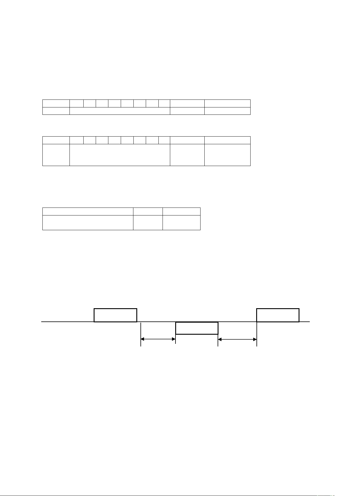
2.2 Communication format
2.2.1 Function format
(1) Read Input Registers (0x04)
[Function]
Read values of input registers. The address and the content of input registers are described in
3. Modbus registers
[Query]
The query message specifies the start address of the register and the number of registers. The register address
starts at zero: register 30001 is addressed as 0.
This function can read up to 32 registers in one query.
Here is an example of a request to slave address 1 for reading 3 register values starting from register 31001.
Query
Response
Field
Data
Field
Data
Slave Address
0x01
Slave Address
0x01
Function Code
0x04
Function Code
0x04
Start Address(Upper)
0x03
Data Size(Bytes)
0x06
Start Address(Lower)
0xE8
Data1(Upper)
0xXX
Number of Registers(Upper)
0x00
Data1(Lower)
0xXX
Number of Registers(Lower)
0x03
Data2(Upper)
0xXX
Error Check CRC16(Lower)
0x30
Data2(Lower)
0xXX
Error Check CRC16(Upper)
0x7B
Data3(Upper)
0xXX
Data3(Lower)
0xXX
Error Check CRC16(Lower)
0xXX
Error Check CRC16(Upper)
0xXX

4P642495-1– 2020.10 Page 12 of 52
(2) Preset Single Register (0x06)
[Function]
Write a value to a holding register. In case of broadcast, the value is written to the same holding register of all
slave units. The address and the content of the holding registers are described in
3. Modbus registers
[Query]
The query message specifies the start address of the register and a value. The register address starts at zero:
register 40001 is addressed as 0. Here is an example of a request to slave address 1 for writing the value ‘2’ to
register 42002.
Query
Response
Field
Data
Field
Data
Slave Address
0x01
Slave Address
0x01
Function Code
0x06
Function Code
0x06
Address(Upper)
0x07
Address(Upper)
0x07
Address(Lower)
0xD1
Address(Lower)
0xD1
Value(Upper)
0x00
Value(Upper)
0x00
Value (Lower)
0x02
Value (Lower)
0x02
Error Check CRC16(Lower)
0x59
Error Check CRC16(Lower)
0x59
Error Check CRC16(Upper)
0x46
Error Check CRC16(Upper)
0x46
(3) Preset Multiple Registers (0x10)
[Function]
Write values to holding registers. In case of broadcast, the values are written to the same holding registers of
all slave units. The address and the content of holding registers are described in
3. Modbus registers
[Query]
The query message specifies the start address of the register, size of data and values. The register address
starts at zero: register 40001 is addressed as 0. This function can write up to 30 registers in one query. Here is
an example of a request to slave address 1 for writing 2 values to register 42001 and to register 42002.
Query
Response
Field
Data
Field
Data
Slave Address
0x01
Slave Address
0x01
Function Code
0x10
Function Code
0x10
Start Address(Upper)
0x07
Start Address(Upper)
0x07
Start Address(Lower)
0xD0
Start Address(Lower)
0xD0
Number of Registers(Upper)
0x00
Number of Registers(Upper)
0x00
Number of Registers(Lower)
0x02
Number of Registers(Lower)
0x02
Data Size(bytes)
0x04
Error Check CRC16(Lower)
0x41
Value1(Upper)
0x00
Error Check CRC16(Upper)
0x45
Value1(Lower)
0x10
Value2(Upper)
0x00
Value2(Lower)
0x01
Error Check CRC16(Lower)
0x18
Error Check CRC16(Upper)
0xC6

4P642495-1– 2020.10 Page 13 of 52
(4) Exception response
In case the query message is faulty, the Modbus Interface DIII will reply an exception response. In normal
conditions the function code of the response message is the same as the query message. But in case of an
error, 0x80 is added to the function code of the response message.
The exception response includes the exception code, indicating the cause of the error.
Exception code
Name
Cause
0x01
Illegal function
This function code is not supported.
0x02
Illegal data address
Access was attempted to an unassigned register
address.
0x03
Illegal data
This query includes unauthorized data.
[Example of exception response]
In the case of setting an illegal mode to the holding register address 42002.
Query
Response
Field
Data
Field
Data
Slave Address
0x01
Slave Address
0x01
Function Code
0x06
Function Code
0x86
Start Address(Upper)
0x07
Exception Code
0x03
Start Address(Lower)
0xD1
Error Check(Lower)
0x02
Number of Registers(Upper)
0x01
Error Check(Upper)
0x61
Number of Registers(Lower)
0x0F
Error Check(Lower)
0x99
Error Check(Upper)
0x13
4P642495-1– 2020.10 Page 14 of 52
2.2.2 Character format
Each byte of a message is sent as character data as follows.
A character consists of start bit (0), 8 bits data, parity bit and stop bit (1). One character size is always 11 bits
and stop bit 1 or 2 is selected by parity bit.
[Non Parity]
0 (LSB)
1 2 3 4 5 6 7 8 9
10 (MSB)
Start bit
Data
Stop bit 1
Stop bit 2
[Parity]
0 (LSB)
1 2 3 4 5 6 7 8 9
10 (MSB)
Start bit
Data
Parity bit
(Odd or
Even)
Stop bit 2
2.2.3 Silent internal time
Every frame needs to have silent interval time (T1-T2-T3-T4) before and after. The silent interval time is
depending on communication speed.
Baud Rate(bps)
9600
19200
Silent Interval Time(ms)
(T1-T2-T3-T4)
5
2,5
2.2.5 Response time
This Modbus Interface DIII responds a message after response time(t1) when this Modbus Interface DIII
receives a query message. The response time(t1) of this adaptor is “Silent Interval Time(T1-T2-T3-T4) + 20ms”.
Modbus master needs to wait to send next query message for time interval(t2) when the modbus master
receives a response from the Modbus Interface DIII. The time interval(t2) should be more than “Silent Interval
Time(T1-T2-T3-T4) + 20ms”.
Modbus master
Modbus Interface DIII
Query message
Response
Query message
t1
t2
t1 = (T1-T2-T3-T4) + 20 (ms)
t2 >= (T1-T2-T3-T4) + 20 (ms)
4P642495-1– 2020.10 Page 15 of 52
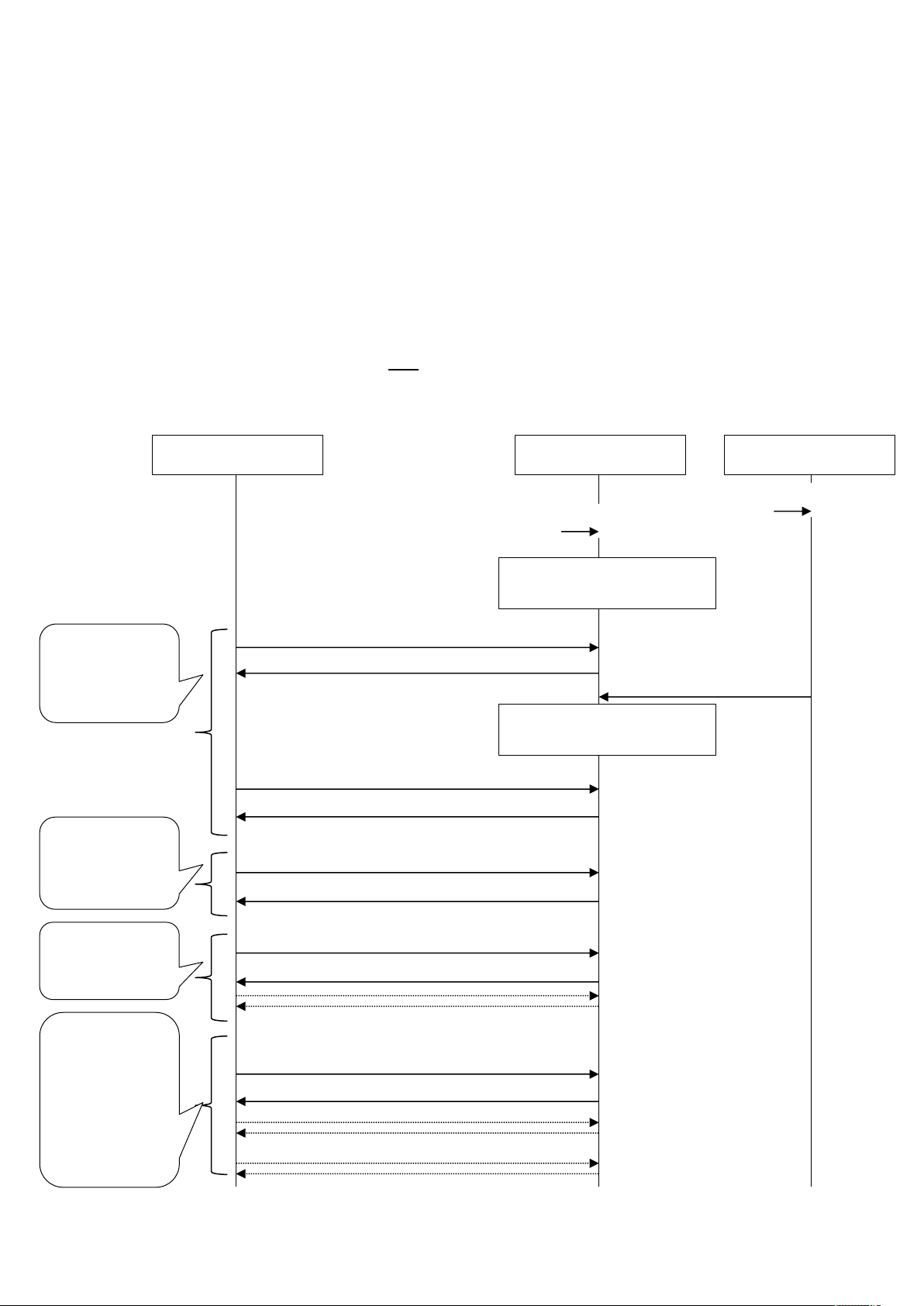
2.3 Communication procedure
2.3.1 System initialisation
At startup:
- All input registers have values 0.
After the discovery of the DIII connected units, the “DIII unit connected status bit” (see Input registers 30002
till 30006) will be updated to “1: connected“ and the input registers of the connected DIII units (30001 and
higher) will have the correct values.
- All the holding registers have initial values 0.
After the discovery of the DIII connected units, the “DIII unit connected status bit” (see input registers 30002
till 30006) will be updated to “1: connected” and the holding registers of the connected DIII units (42001 and
higher) will be updated to the actual values once.
Attention: The holding values receive the actual values at the detection time only. This means this will only
happen once. (Remark: also not during rediscovery)
Retrieve status
Return: Busy
Check Modbus Interface DIII status (30001)
BMS
Modbus Interface DIII
DIII unit
Power on
Power on
Modbus Interface DIII status
(30001 bit 0): Busy
Return: Ready
Check Modbus Interface DIII status (30001)
Modbus Interface DIII status
(30001 bit 0): Ready
Return: Ready
Check DIII unit connected status (30002-5)
Check status when
Modbus Interface
DIII is ready
BMS gets all DIII
units connected
addresses
Return values
Check DIII unit capabilities
BMS gets all DIII
units capabilities
BMS gets all DIII
units current
status by reading
the input registers
and read all
values of the
holding registers
Return values
Check DIII unit status (input registers) & read
holding registers
4P642495-1– 2020.10 Page 16 of 52
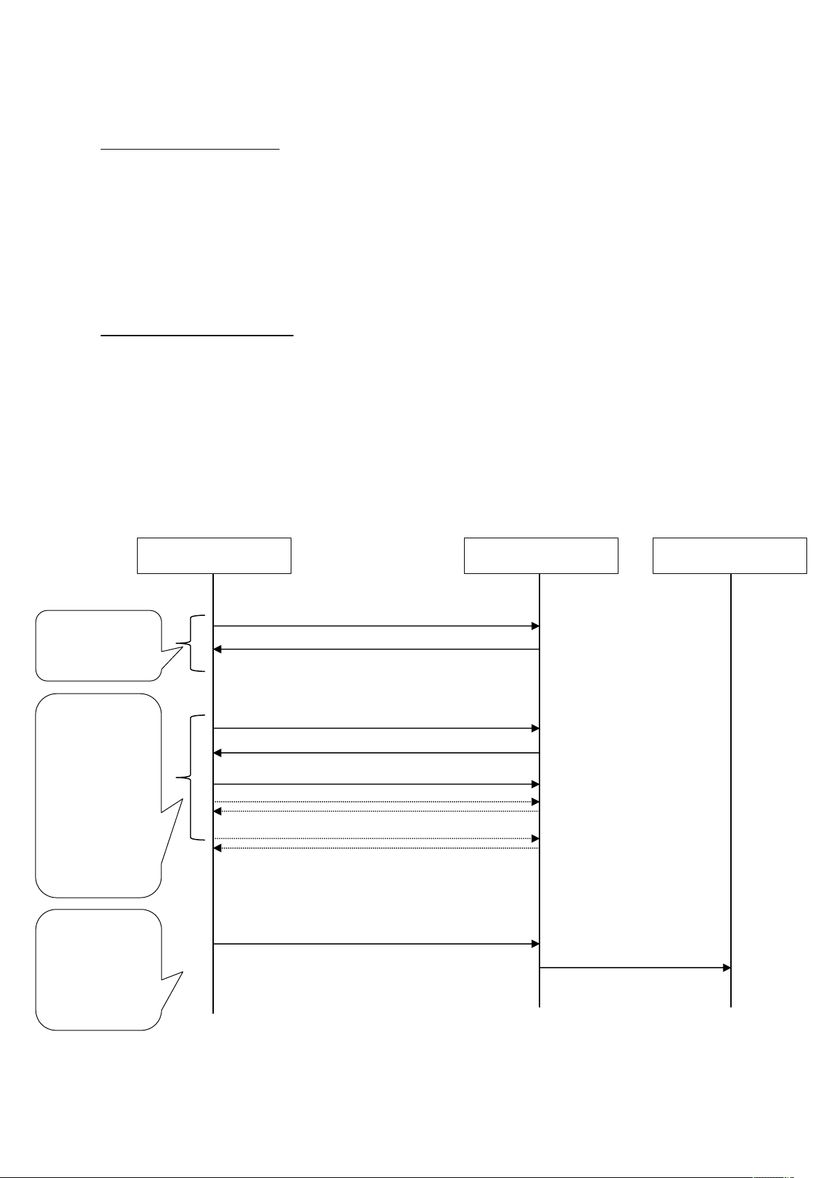
2.3.2 Monitor and operate units from the BMS
Input registers of each DIII unit: 30001 and higher
The input registers will contain the status of the connected DIII units.
In case the DIII communication is interrupted (see Input registers 30006 till 30009): then the last
communicated values will remain, until the DIII communication is restored.
Status changes are communicated continuously to the input registers, meaning the input registers will contain
the actual values.
Holding registers of each DIII unit: 42001 and higher
- Writing instructions to change a unit status (Preset Single or Multiple Registers)
When a value is written to a holding register, it will be communicated to the DIII units.
Attention: Modbus Interface DIII sends the command to a unit when the value of a Holding Register is
changed. Especially in case that indoor units are operated from the user interface, the BMS should always get
the status of indoor units and copy the received status to the Holding Registers.
Note: at start-up of the system (See 2.3.1 System initialisation) and the initial discovery of the DIII connected
units, the Modbus Interface DIII put the actual status in the holding registers. (Remark: not during rediscovery.)
Change on/off
Return: status
Check communication status (30006-9)
BMS
Modbus Interface DIII
DIII unit
BMS checks
communication
status
Copy:
BMS gets all DIII
units current
status by reading
the input registers
and copies to the
related bits (preset) to the holding
registers
Return values
Get DIII unit status (input registers)
Preset DIII unit status to the holding register
Command:
BMS changes a
value in the
holding registers
Preset On/Off bit to the holding register
 Loading...