

Daikin ERGA04EAV3, ERGA06EAV3, ERGA08EAV3, EHVH04SU18EA6V, EHVH04SU23EA6V Installer reference guide
...
Installer reference guide
Daikin Altherma 3 R F
ERGA04EAV3(A)
ERGA06EAV3(A)
ERGA08EAV3(A)
EHVH04SU18EA6V
EHVH04SU23EA6V
EHVH08SU18EA6V
EHVH08SU23EA6V

Table of contents
Table of contents
1 About the documentation 6
1.1 About this document ...................................................................................................................................................... 6
1.2 Meaning of warnings and symbols................................................................................................................................. 7
1.3 Installer reference guide at a glance .............................................................................................................................. 8
2 General safety precautions 9
2.1 For the installer............................................................................................................................................................... 9
2.1.1 General ........................................................................................................................................................... 9
2.1.2 Installation site ............................................................................................................................................... 10
2.1.3 Refrigerant — in case of R410A or R32.......................................................................................................... 10
2.1.4 Water .............................................................................................................................................................. 12
2.1.5 Electrical ......................................................................................................................................................... 12
3 Specific installer safety instructions 15
3.1 Instructions for equipment using R32 refrigerant ......................................................................................................... 18
4 About the box 20
4.1 Overview: About the box ................................................................................................................................................ 20
4.2 Outdoor unit ................................................................................................................................................................... 20
4.2.1 To unpack the outdoor unit ........................................................................................................................... 20
4.2.2 To handle the outdoor unit ............................................................................................................................ 21
4.2.3 To remove the accessories from the outdoor unit........................................................................................ 21
4.3 Indoor unit ...................................................................................................................................................................... 22
4.3.1 To unpack the indoor unit .............................................................................................................................. 22
4.3.2 To remove the accessories from the indoor unit .......................................................................................... 22
4.3.3 To handle the indoor unit............................................................................................................................... 23
4.4 Domestic hot water tank kit ........................................................................................................................................... 23
4.4.1 To remove the accessories from the domestic hot water tank kit ............................................................... 23
4.5 Checklist for the required DHW accessories.................................................................................................................. 23
5 About the units and options 25
5.1 Overview: About the units and options.......................................................................................................................... 25
5.2 Identification ................................................................................................................................................................... 25
5.2.1 Identification label: Outdoor unit .................................................................................................................. 25
5.2.2 Identification label: Indoor unit ..................................................................................................................... 26
5.3 Combining units and options.......................................................................................................................................... 26
5.3.1 Possible options for the outdoor unit ............................................................................................................ 26
5.3.2 Possible options for the indoor unit............................................................................................................... 27
6 Application guidelines 30
6.1 Overview: Application guidelines ................................................................................................................................... 30
6.2 Setting up the space heating/cooling system ................................................................................................................ 30
6.2.1 Single room ..................................................................................................................................................... 31
6.2.2 Multiple rooms – OneLWT zone ................................................................................................................... 35
6.2.3 Multiple rooms – TwoLWT zones.................................................................................................................. 39
6.3 Setting up an auxiliary heat source for space heating ................................................................................................... 41
6.4 Setting up the domestic hot water tank......................................................................................................................... 44
6.4.1 System layout – Integrated DHW tank........................................................................................................... 44
6.4.2 Selecting the volume and desired temperature for the DHW tank .............................................................. 44
6.4.3 Setup and configuration – DHW tank ............................................................................................................ 46
6.4.4 DHW pump for instant hot water .................................................................................................................. 46
6.4.5 DHW pump for disinfection ........................................................................................................................... 47
6.5 Setting up the energy metering...................................................................................................................................... 47
6.5.1 Produced heat ................................................................................................................................................ 47
6.5.2 Consumed energy........................................................................................................................................... 48
6.5.3 Normal kWh rate power supply ..................................................................................................................... 48
6.5.4 Preferential kWh rate power supply .............................................................................................................. 50
6.6 Setting up the power consumption control ................................................................................................................... 51
6.6.1 Permanent power limitation .......................................................................................................................... 51
6.6.2 Power limitation activated by digital inputs .................................................................................................. 51
6.6.3 Power limitation process................................................................................................................................ 53
6.7 Setting up an external temperature sensor ................................................................................................................... 53
Installer reference guide
2
7 Unit installation 55
7.1 Preparing the installation site......................................................................................................................................... 55
7.1.1 Installation site requirements of the outdoor unit........................................................................................ 55
ERGA04~08EAV3(A) + EHVH04+08SU18+23EA6V
Daikin Altherma 3 R F
4P629090-1 – 2020.08

Table of contents
7.1.2 Additional installation site requirements of the outdoor unit in cold climates............................................ 58
7.1.3 Installation site requirements of the indoor unit .......................................................................................... 59
7.2 Opening and closing the units ........................................................................................................................................ 62
7.2.1 About opening the units................................................................................................................................. 62
7.2.2 To open the outdoor unit ............................................................................................................................... 62
7.2.3 To close the outdoor unit ............................................................................................................................... 62
7.2.4 To open the indoor unit ................................................................................................................................. 62
7.2.5 To lower the switch box on the indoor unit .................................................................................................. 64
7.2.6 To close the indoor unit ................................................................................................................................. 65
7.3 Mounting the outdoor unit............................................................................................................................................. 65
7.3.1 About mounting the outdoor unit ................................................................................................................. 65
7.3.2 Precautions when mounting the outdoor unit .............................................................................................. 66
7.3.3 To provide the installation structure ............................................................................................................. 66
7.3.4 To install the outdoor unit ............................................................................................................................. 69
7.3.5 To provide drainage........................................................................................................................................ 70
7.3.6 To prevent the outdoor unit from falling over .............................................................................................. 71
7.4 Mounting the indoor unit ............................................................................................................................................... 72
7.4.1 About mounting the indoor unit .................................................................................................................... 72
7.4.2 Precautions when mounting the indoor unit................................................................................................. 72
7.4.3 To install the indoor unit ................................................................................................................................ 72
7.4.4 To connect the drain hose to the drain ......................................................................................................... 73
8 Piping installation 75
8.1 Preparing refrigerant piping ........................................................................................................................................... 75
8.1.1 Refrigerant piping requirements.................................................................................................................... 75
8.1.2 Refrigerant piping insulation .......................................................................................................................... 76
8.2 Preparing water piping ................................................................................................................................................... 76
8.2.1 Water circuit requirements............................................................................................................................ 76
8.2.2 Formula to calculate the expansion vessel pre-pressure .............................................................................. 80
8.2.3 To check the water volume and flow rate ..................................................................................................... 80
8.2.4 Changing the pre-pressure of the expansion vessel...................................................................................... 82
8.2.5 To check the water volume: Examples .......................................................................................................... 83
8.3 Connecting the refrigerant piping .................................................................................................................................. 84
8.3.1 About connecting the refrigerant piping ....................................................................................................... 84
8.3.2 Precautions when connecting the refrigerant piping .................................................................................... 84
8.3.3 Guidelines when connecting the refrigerant piping ...................................................................................... 85
8.3.4 Pipe bending guidelines ................................................................................................................................. 86
8.3.5 To flare the pipe end ...................................................................................................................................... 86
8.3.6 To braze the pipe end..................................................................................................................................... 87
8.3.7 Using the stop valve and service port ............................................................................................................ 87
8.3.8 To connect the refrigerant piping to the outdoor unit ................................................................................. 89
8.3.9 To connect the refrigerant piping to the indoor unit .................................................................................... 89
8.4 Checking the refrigerant piping...................................................................................................................................... 90
8.4.1 About checking the refrigerant piping ........................................................................................................... 90
8.4.2 Precautions when checking the refrigerant piping........................................................................................ 90
8.4.3 To check for leaks ........................................................................................................................................... 91
8.4.4 To perform vacuum drying............................................................................................................................. 91
8.4.5 To insulate the refrigerant piping .................................................................................................................. 92
8.5 Charging refrigerant........................................................................................................................................................ 93
8.5.1 About charging refrigerant............................................................................................................................. 93
8.5.2 Precautions when charging refrigerant ......................................................................................................... 94
8.5.3 To determine the additional refrigerant amount .......................................................................................... 94
8.5.4 To determine the complete recharge amount .............................................................................................. 94
8.5.5 To charge additional refrigerant .................................................................................................................... 94
8.5.6 To fix the fluorinated greenhouse gases label ............................................................................................... 95
8.6 Connecting water piping................................................................................................................................................. 95
8.6.1 About connecting the water piping ............................................................................................................... 95
8.6.2 Precautions when connecting the water piping ............................................................................................ 96
8.6.3 To connect the water piping .......................................................................................................................... 96
8.6.4 To connect the water piping for domestic hot water.................................................................................... 98
8.6.5 To connect the recirculation piping ............................................................................................................... 101
8.6.6 To fill the water circuit ................................................................................................................................... 101
8.6.7 To fill the domestic hot water tank ................................................................................................................ 101
8.6.8 To insulate the water piping .......................................................................................................................... 102
ERGA04~08EAV3(A) + EHVH04+08SU18+23EA6V
Daikin Altherma 3 R F
4P629090-1 – 2020.08
9 Electrical installation 103
9.1 About connecting the electrical wiring .......................................................................................................................... 103
9.1.1 Precautions when connecting the electrical wiring....................................................................................... 104
9.1.2 Guidelines when connecting the electrical wiring......................................................................................... 105
9.1.3 Specifications of standard wiring components.............................................................................................. 106
Installer reference guide
3

Table of contents
9.1.4 About electrical compliance........................................................................................................................... 106
9.1.5 About preferential kWh rate power supply ................................................................................................... 107
9.1.6 Overview of electrical connections except external actuators ..................................................................... 107
9.2 Connections to the outdoor unit.................................................................................................................................... 108
9.2.1 To connect the electrical wiring to the outdoor unit .................................................................................... 108
9.3 Connections to the indoor unit ...................................................................................................................................... 110
9.3.1 To connect the main power supply................................................................................................................ 114
9.3.2 To connect the backup heater power supply ................................................................................................ 116
9.3.3 To connect the shut-off valve ........................................................................................................................ 118
9.3.4 To connect the electricity meters .................................................................................................................. 119
9.3.5 To connect the domestic hot water pump .................................................................................................... 119
9.3.6 To connect the alarm output ......................................................................................................................... 120
9.3.7 To connect the space cooling/heating ON/OFF output................................................................................. 121
9.3.8 To connect the changeover to external heat source..................................................................................... 122
9.3.9 To connect the power consumption digital inputs........................................................................................ 123
9.3.10 To connect the safety thermostat (normally closed contact)....................................................................... 124
9.3.11 To connect a Smart Grid................................................................................................................................. 125
9.3.12 To connect the WLAN cartridge (delivered as accessory)............................................................................. 129
9.4 After connecting the electrical wiring to the indoor unit .............................................................................................. 129
10 Configuration 131
10.1 Overview: Configuration ................................................................................................................................................. 131
10.1.1 To access the most used commands ............................................................................................................. 132
10.2 Configuration wizard....................................................................................................................................................... 134
10.3 Possible screens .............................................................................................................................................................. 135
10.3.1 Possible screens: Overview............................................................................................................................ 135
10.3.2 Home screen................................................................................................................................................... 136
10.3.3 Main menu screen.......................................................................................................................................... 139
10.3.4 Menu screen................................................................................................................................................... 140
10.3.5 Setpoint screen............................................................................................................................................... 140
10.3.6 Detailed screen with values ........................................................................................................................... 141
10.3.7 Schedule screen: Example.............................................................................................................................. 141
10.4 Weather-dependent curve ............................................................................................................................................. 146
10.4.1 What is a weather-dependent curve? ........................................................................................................... 146
10.4.2 2-points curve................................................................................................................................................. 146
10.4.3 Slope-offset curve........................................................................................................................................... 147
10.4.4 Using weather-dependent curves.................................................................................................................. 149
10.5 Settings menu ................................................................................................................................................................. 151
10.5.1 Malfunctioning ............................................................................................................................................... 151
10.5.2 Room............................................................................................................................................................... 151
10.5.3 Main zone....................................................................................................................................................... 155
10.5.4 Additional zone............................................................................................................................................... 165
10.5.5 Space heating/cooling.................................................................................................................................... 171
10.5.6 Tank................................................................................................................................................................. 179
10.5.7 User settings................................................................................................................................................... 186
10.5.8 Information..................................................................................................................................................... 191
10.5.9 Installer settings ............................................................................................................................................. 192
10.5.10 Operation........................................................................................................................................................ 209
10.5.11 WLAN .............................................................................................................................................................. 210
10.6 Menu structure: Overview user settings ........................................................................................................................ 212
10.7 Menu structure: Overview installer settings .................................................................................................................. 214
Installer reference guide
4
11 Commissioning 215
11.1 Overview: Commissioning .............................................................................................................................................. 215
11.2 Precautions when commissioning .................................................................................................................................. 216
11.3 Checklist before commissioning ..................................................................................................................................... 216
11.4 Checklist during commissioning ..................................................................................................................................... 217
11.4.1 Minimum flow rate......................................................................................................................................... 217
11.4.2 Air purge function........................................................................................................................................... 217
11.4.3 Operation test run.......................................................................................................................................... 219
11.4.4 Actuator test run ............................................................................................................................................ 220
11.4.5 Underfloor heating screed dryout ................................................................................................................. 221
12 Hand-over to the user 225
13 Maintenance and service 226
13.1 Overview: Maintenance and service .............................................................................................................................. 226
13.2 Maintenance safety precautions .................................................................................................................................... 226
13.3 Yearly maintenance ........................................................................................................................................................ 227
13.3.1 Yearly maintenance outdoor unit: overview ................................................................................................. 227
13.3.2 Yearly maintenance outdoor unit: instructions............................................................................................. 227
ERGA04~08EAV3(A) + EHVH04+08SU18+23EA6V
Daikin Altherma 3 R F
4P629090-1 – 2020.08

Table of contents
13.3.3 Yearly maintenance indoor unit: overview.................................................................................................... 227
13.3.4 Yearly maintenance indoor unit: instructions ............................................................................................... 227
13.4 To drain the domestic hot water tank............................................................................................................................ 230
13.5 To inspect the inside of the domestic hot water tank ................................................................................................... 231
13.6 About cleaning the water filter in case of trouble ......................................................................................................... 232
13.6.1 To remove the water filter............................................................................................................................. 232
13.6.2 To clean the water filter in case of trouble.................................................................................................... 233
13.6.3 To install the water filter................................................................................................................................ 234
14 Troubleshooting 235
14.1 Overview: Troubleshooting ............................................................................................................................................ 235
14.2 Precautions when troubleshooting ................................................................................................................................ 235
14.3 Solving problems based on symptoms ........................................................................................................................... 236
14.3.1 Symptom: The unit is NOT heating or cooling as expected........................................................................... 236
14.3.2 Symptom: Hot water does NOT reach the desired temperature.................................................................. 237
14.3.3 Symptom: The compressor does NOT start (space heating or domestic water heating) ............................ 237
14.3.4 Symptom: The system is making gurgling noises after commissioning........................................................ 237
14.3.5 Symptom: The pump is making noise (cavitation)......................................................................................... 238
14.3.6 Symptom: The pressure relief valve opens.................................................................................................... 238
14.3.7 Symptom: The water pressure relief valve leaks........................................................................................... 239
14.3.8 Symptom: The space is NOT sufficiently heated at low outdoor temperatures........................................... 239
14.3.9 Symptom: The pressure at the tapping point is temporarily unusually high................................................ 240
14.3.10 Symptom: Decoration panels are pushed away due to a swollen tank ........................................................ 240
14.3.11 Symptom: Tank disinfection function is NOT completed correctly (AH-error)............................................. 240
14.4 Solving problems based on error codes ......................................................................................................................... 241
14.4.1 To display the help text in case of a malfunction.......................................................................................... 241
14.4.2 Error codes: Overview.................................................................................................................................... 242
15 Disposal 246
15.1 Overview: Disposal.......................................................................................................................................................... 246
15.2 To pump down ................................................................................................................................................................ 246
15.3 To start and stop forced cooling..................................................................................................................................... 247
16 Technical data 249
16.1 Piping diagram: Outdoor unit ......................................................................................................................................... 249
16.2 Piping diagram: Indoor unit ............................................................................................................................................ 251
16.3 Wiring diagram: Outdoor unit ........................................................................................................................................ 252
16.4 Wiring diagram: Indoor unit ........................................................................................................................................... 254
16.5 Table 1 – Maximum refrigerant charge allowed in a room: indoor unit ....................................................................... 260
16.6 Table 2 – Minimum floor area: indoor unit .................................................................................................................... 261
16.7 Table 3 – Minimum venting opening area for natural ventilation: indoor unit ............................................................ 261
16.8 ESP curve: Indoor unit..................................................................................................................................................... 263
16.9 Technical specifications: Domestic hot water tank........................................................................................................ 263
16.9.1 Test results in accordance with EN12897 (2016).......................................................................................... 263
16.9.2 Warning label.................................................................................................................................................. 264
17 Glossary 265
18 Field settings table 266
ERGA04~08EAV3(A) + EHVH04+08SU18+23EA6V
Daikin Altherma 3 R F
4P629090-1 – 2020.08
Installer reference guide
5

1 | About the documentation
1 About the documentation
In this chapter
1.1 About this document.............................................................................................................................................................. 6
1.2 Meaning of warnings and symbols......................................................................................................................................... 7
1.3 Installer reference guide at a glance...................................................................................................................................... 8
1.1 About this document
Target audience
Authorised installers
Documentation set
INFORMATION
Make sure that the user has the printed documentation and ask him/her to keep it
for future reference.
This document is part of a documentation set. The complete set consists of:
▪ General safety precautions:
- Safety instructions that you must read before installing
- Format: Paper (in the box of the indoor unit)
▪ Indoor unit installation manual:
- Installation instructions
- Format: Paper (in the box of the indoor unit)
▪ Outdoor unit installation manual:
- Installation instructions
- Format: Paper (in the box of the outdoor unit)
▪ Installer reference guide:
- Preparation of the installation, good practices, reference data,…
- Format: Digital files on http://www.daikineurope.com/support-and-manuals/
product-information/
▪ Addendum book for optional equipment:
- Additional info about how to install optional equipment
- Format: Paper (in the box of the indoor unit) + Digital files on http://
www.daikineurope.com/support-and-manuals/product-information/
Installer reference guide
6
Latest revisions of the supplied documentation may be available on the regional
Daikin website or via your dealer.
The original documentation is written in English. All other languages are
translations.
Technical engineering data
▪ A subset of the latest technical data is available on the regional Daikin website
(publicly accessible).
▪ The full set of latest technical data is available on the Daikin Business Portal
(authentication required).
ERGA04~08EAV3(A) + EHVH04+08SU18+23EA6V
Daikin Altherma 3 R F
4P629090-1 – 2020.08
1.2 Meaning of warnings and symbols
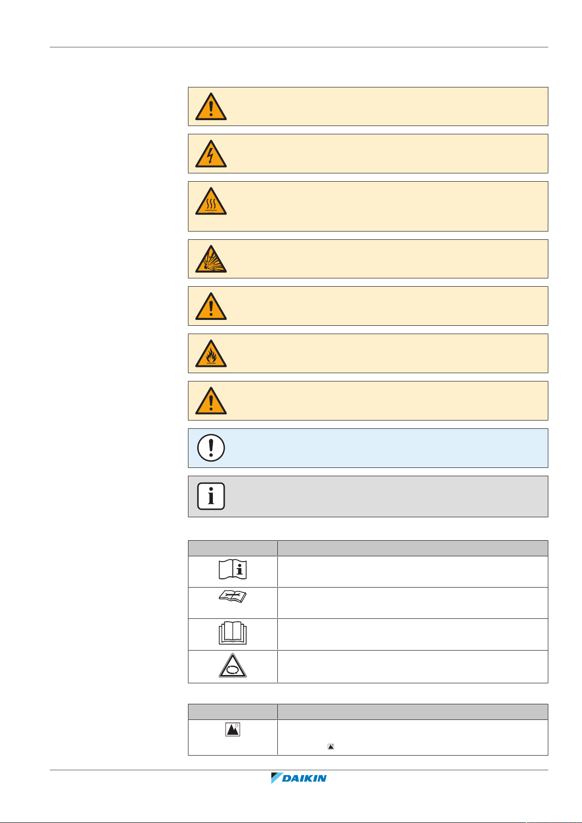
DANGER
Indicates a situation that results in death or serious injury.
DANGER: RISK OF ELECTROCUTION
Indicates a situation that could result in electrocution.
DANGER: RISK OF BURNING/SCALDING
Indicates a situation that could result in burning/scalding because of extreme hot or
cold temperatures.
DANGER: RISK OF EXPLOSION
Indicates a situation that could result in explosion.
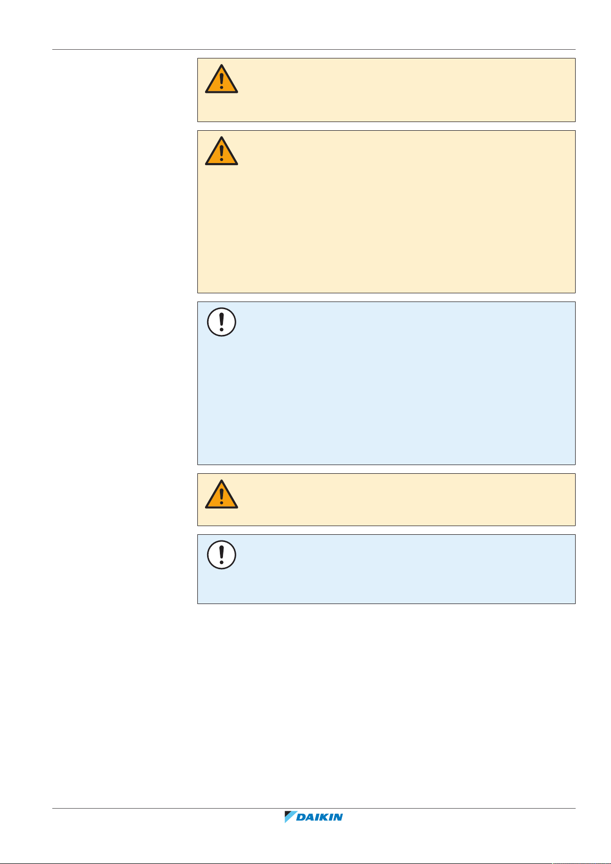
WARNING
Indicates a situation that could result in death or serious injury.
1 | About the documentation
WARNING: FLAMMABLE MATERIAL
CAUTION
Indicates a situation that could result in minor or moderate injury.
NOTICE
Indicates a situation that could result in equipment or property damage.
INFORMATION
Indicates useful tips or additional information.
Symbols used on the unit:
Symbol Explanation
Before installation, read the installation and operation
manual, and the wiring instruction sheet.
Before performing maintenance and service tasks, read the
service manual.
For more information, see the installer and user reference
guide.
ERGA04~08EAV3(A) + EHVH04+08SU18+23EA6V
Daikin Altherma 3 R F
4P629090-1 – 2020.08
The unit contains rotating parts. Be careful when servicing or
inspecting the unit.
Symbols used in the documentation:
Symbol Explanation
Indicates a figure title or a reference to it.
Example: " 1–3 Figure title" means "Figure 3 in chapter 1".
Installer reference guide
7
1 | About the documentation
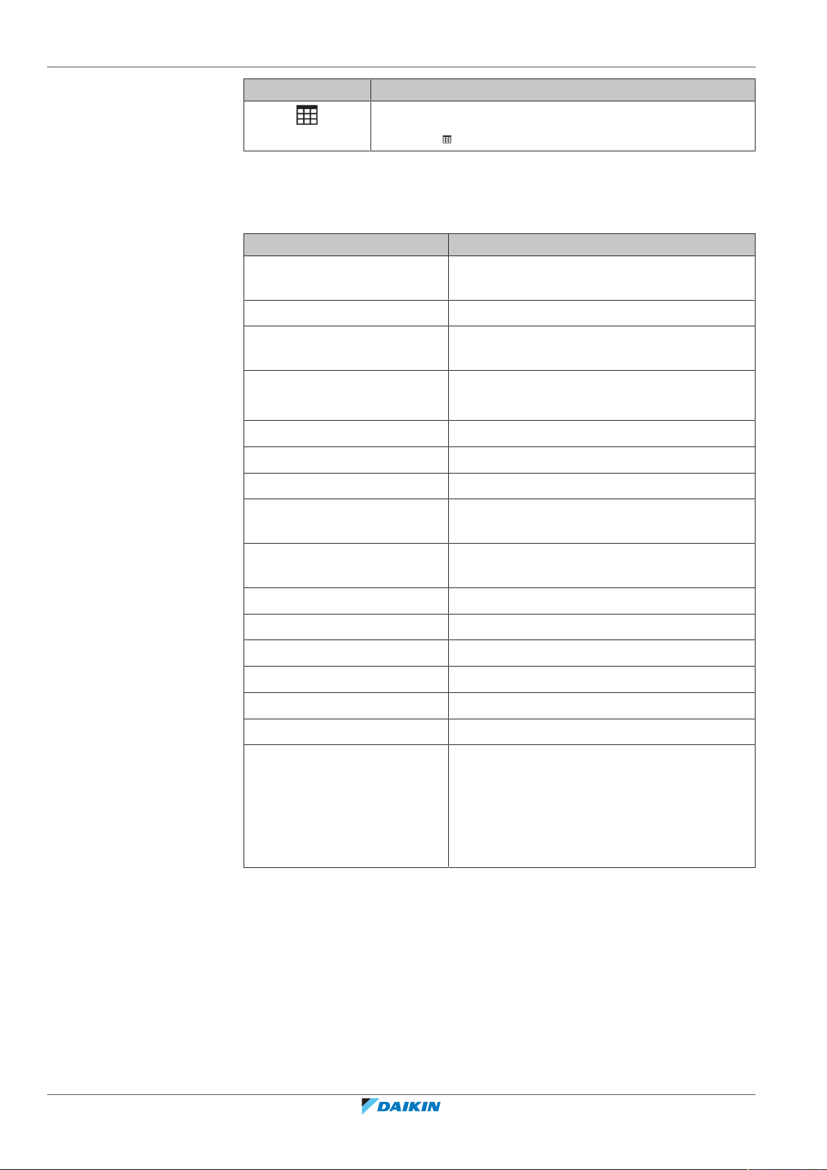
1.3 Installer reference guide at a glance
General safety precautions Safety instructions that you must read before
About the documentation What documentation exists for the installer
About the box How to unpack the units and remove their
About the units and options ▪ How to identify the units
Application guidelines Various installation setups of the system
Symbol Explanation
Indicates a table title or a reference to it.
Example: " 1–3 Table title" means "Table 3 in chapter 1".
Chapter Description
installing
accessories
▪ Possible combinations of units and options
Preparation What to do and know before going on‑site
Installation What to do and know to install the system
Configuration What to do and know to configure the system
after it is installed
Commissioning What to do and know to commission the system
after it is configured
Hand‑over to the user What to give and explain to the user
Maintenance and service How to maintain and service the units
Troubleshooting What to do in case of problems
Disposal How to dispose of the system
Technical data Specifications of the system
Glossary Definition of terms
Field settings table Table to be filled in by the installer, and kept for
future reference
Note: There is also an installer settings table in
the user reference guide. This table has to be
filled in by the installer and handed over to the
user.
Installer reference guide
8
ERGA04~08EAV3(A) + EHVH04+08SU18+23EA6V
Daikin Altherma 3 R F
4P629090-1 – 2020.08
2 General safety precautions
In this chapter
2.1 For the installer....................................................................................................................................................................... 9
2.1.1 General ................................................................................................................................................................... 9
2.1.2 Installation site ....................................................................................................................................................... 10
2.1.3 Refrigerant — in case of R410A or R32 ................................................................................................................. 10
2.1.4 Water ...................................................................................................................................................................... 12
2.1.5 Electrical ................................................................................................................................................................. 12
2.1 For the installer
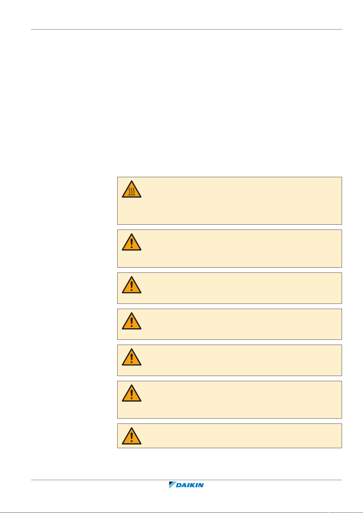
2.1.1 General
If you are NOT sure how to install or operate the unit, contact your dealer.
DANGER: RISK OF BURNING/SCALDING
▪ Do NOT touch the refrigerant piping, water piping or internal parts during and
immediately after operation. It could be too hot or too cold. Give it time to return
to normal temperature. If you must touch it, wear protective gloves.
▪ Do NOT touch any accidental leaking refrigerant.
2 | General safety precautions
WARNING
Improper installation or attachment of equipment or accessories could result in
electrical shock, short-circuit, leaks, fire or other damage to the equipment. Only use
accessories, optional equipment and spare parts made or approved by Daikin.
WARNING
Make sure installation, testing and applied materials comply with applicable
legislation (on top of the instructions described in the Daikin documentation).
CAUTION
Wear adequate personal protective equipment (protective gloves, safety glasses,…)
when installing, maintaining or servicing the system.
WARNING
Tear apart and throw away plastic packaging bags so that nobody, especially
children, can play with them. Possible risk: suffocation.
WARNING
Provide adequate measures to prevent that the unit can be used as a shelter by small
animals. Small animals that make contact with electrical parts can cause
malfunctions, smoke or fire.
ERGA04~08EAV3(A) + EHVH04+08SU18+23EA6V
Daikin Altherma 3 R F
4P629090-1 – 2020.08
CAUTION
Do NOT touch the air inlet or aluminium fins of the unit.
Installer reference guide
9
2 | General safety precautions
In accordance with the applicable legislation, it might be necessary to provide a
logbook with the product containing at least: information on maintenance, repair
work, results of tests, stand-by periods,…
Also, at least, following information MUST be provided at an accessible place at the
product:
▪ Instructions for shutting down the system in case of an emergency
▪ Name and address of fire department, police and hospital
▪ Name, address and day and night telephone numbers for obtaining service
In Europe, EN378 provides the necessary guidance for this logbook.
CAUTION
▪ Do NOT place any objects or equipment on top of the unit.
▪ Do NOT sit, climb or stand on the unit.
NOTICE
Works executed on the outdoor unit are best done under dry weather conditions to
avoid water ingress.
2.1.2 Installation site
▪ Provide sufficient space around the unit for servicing and air circulation.
▪ Make sure the installation site withstands the weight and vibration of the unit.
▪ Make sure the area is well ventilated. Do NOT block any ventilation openings.
▪ Make sure the unit is level.
Do NOT install the unit in the following places:
▪ In potentially explosive atmospheres.
▪ In places where there is machinery that emits electromagnetic waves.
Electromagnetic waves may disturb the control system, and cause malfunction of
the equipment.
▪ In places where there is a risk of fire due to the leakage of flammable gases
(example: thinner or gasoline), carbon fibre, ignitable dust.
▪ In places where corrosive gas (example: sulphurous acid gas) is produced.
Corrosion of copper pipes or soldered parts may cause the refrigerant to leak.
2.1.3 Refrigerant — in case of R410A or R32
If applicable. See the installation manual or installer reference guide of your
application for more information.
Installer reference guide
10
NOTICE
Make sure refrigerant piping installation complies with applicable legislation. In
Europe, EN378 is the applicable standard.
NOTICE
Make sure the field piping and connections are NOT subjected to stress.
ERGA04~08EAV3(A) + EHVH04+08SU18+23EA6V
Daikin Altherma 3 R F
4P629090-1 – 2020.08
2 | General safety precautions
WARNING
During tests, NEVER pressurize the product with a pressure higher than the
maximum allowable pressure (as indicated on the nameplate of the unit).
WARNING
Take sufficient precautions in case of refrigerant leakage. If refrigerant gas leaks,
ventilate the area immediately. Possible risks:
▪ Excessive refrigerant concentrations in a closed room can lead to oxygen
deficiency.
▪ Toxic gas might be produced if refrigerant gas comes into contact with fire.
DANGER: RISK OF EXPLOSION
Pump down – Refrigerant leakage. If you want to pump down the system, and there
is a leak in the refrigerant circuit:
▪ Do NOT use the unit's automatic pump down function, with which you can collect
all refrigerant from the system into the outdoor unit. Possible consequence: Selfcombustion and explosion of the compressor because of air going into the
operating compressor.
▪ Use a separate recovery system so that the unit's compressor does NOT have to
operate.
WARNING
ALWAYS recover the refrigerant. Do NOT release them directly into the environment.
Use a vacuum pump to evacuate the installation.
NOTICE
After all the piping has been connected, make sure there is no gas leak. Use nitrogen
to perform a gas leak detection.
NOTICE
▪ To avoid compressor breakdown, do NOT charge more than the specified amount
of refrigerant.
▪ When the refrigerant system is to be opened, refrigerant MUST be treated
according to the applicable legislation.
WARNING
Make sure there is no oxygen in the system. Refrigerant may only be charged after
performing the leak test and the vacuum drying.
Possible consequence: Self-combustion and explosion of the compressor because of
oxygen going into the operating compressor.
▪ In case recharge is required, see the nameplate of the unit. It states the type of
refrigerant and necessary amount.
ERGA04~08EAV3(A) + EHVH04+08SU18+23EA6V
Daikin Altherma 3 R F
4P629090-1 – 2020.08
▪ The unit is factory charged with refrigerant and depending on pipe sizes and pipe
lengths some systems require additional charging of refrigerant.
▪ Only use tools exclusively for the refrigerant type used in the system, this to
ensure pressure resistance and prevent foreign materials from entering into the
system.
▪ Charge the liquid refrigerant as follows:
Installer reference guide
11
2 | General safety precautions
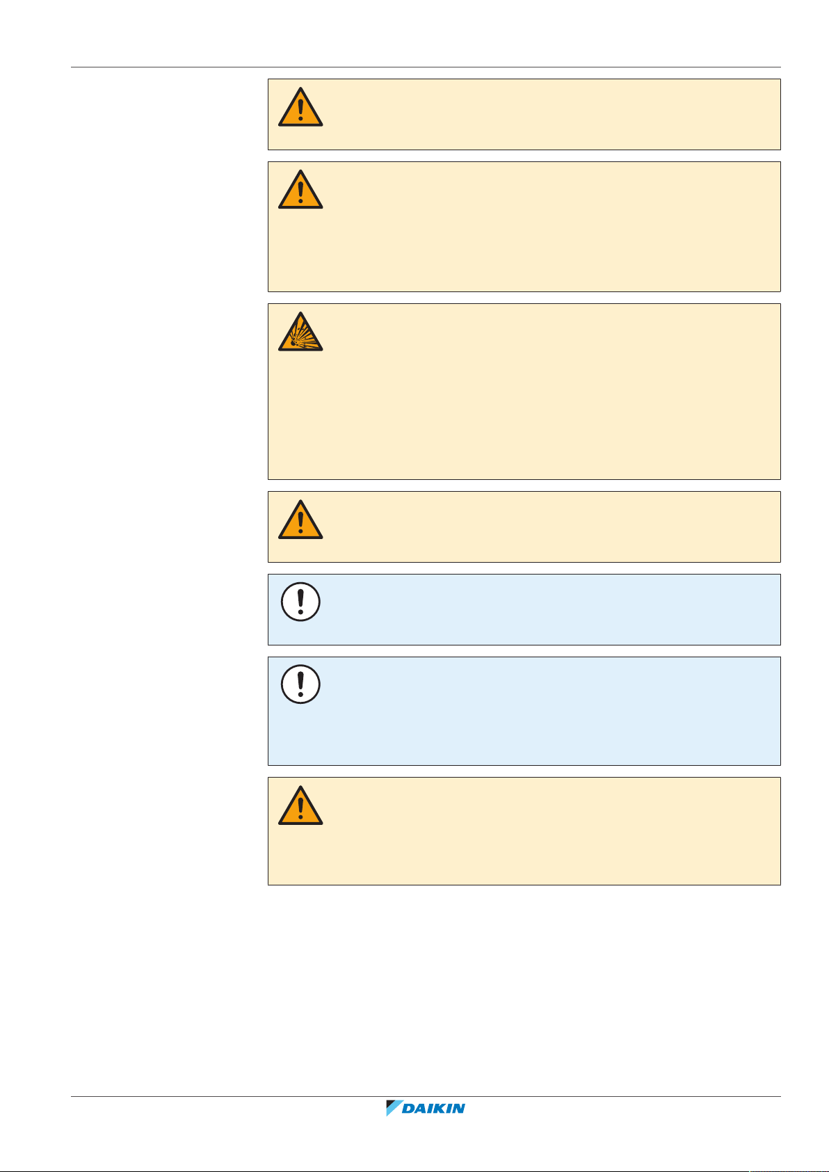
If Then
A siphon tube is present
Charge with the cylinder upright.
(i.e., the cylinder is marked with "Liquid
filling siphon attached")
A siphon tube is NOT present Charge with the cylinder upside down.
▪ Open refrigerant cylinders slowly.
▪ Charge the refrigerant in liquid form. Adding it in gas form may prevent normal
operation.
CAUTION
When the refrigerant charging procedure is done or when pausing, close the valve of
the refrigerant tank immediately. If the valve is NOT closed immediately, remaining
pressure might charge additional refrigerant. Possible consequence: Incorrect
refrigerant amount.
2.1.4 Water
2.1.5 Electrical
If applicable. See the installation manual or installer reference guide of your
application for more information.
NOTICE
Make sure water quality complies with EU directive 98/83EC.
DANGER: RISK OF ELECTROCUTION
▪ Turn OFF all power supply before removing the switch box cover, connecting
electrical wiring or touching electrical parts.
▪ Disconnect the power supply for more than 10minutes, and measure the voltage
at the terminals of main circuit capacitors or electrical components before
servicing. The voltage MUST be less than 50VDC before you can touch electrical
components. For the location of the terminals, see the wiring diagram.
▪ Do NOT touch electrical components with wet hands.
▪ Do NOT leave the unit unattended when the service cover is removed.
WARNING
If NOT factory installed, a main switch or other means for disconnection, having a
contact separation in all poles providing full disconnection under overvoltage
categoryIII condition, MUST be installed in the fixed wiring.
Installer reference guide
12
ERGA04~08EAV3(A) + EHVH04+08SU18+23EA6V
Daikin Altherma 3 R F
4P629090-1 – 2020.08
2 | General safety precautions
WARNING
▪ ONLY use copper wires.
▪ Make sure the field wiring complies with the applicable legislation.
▪ All field wiring MUST be performed in accordance with the wiring diagram
supplied with the product.
▪ NEVER squeeze bundled cables and make sure they do NOT come in contact with
the piping and sharp edges. Make sure no external pressure is applied to the
terminal connections.
▪ Make sure to install earth wiring. Do NOT earth the unit to a utility pipe, surge
absorber, or telephone earth. Incomplete earth may cause electrical shock.
▪ Make sure to use a dedicated power circuit. NEVER use a power supply shared by
another appliance.
▪ Make sure to install the required fuses or circuit breakers.
▪ Make sure to install an earth leakage protector. Failure to do so may cause
electrical shock or fire.
▪ When installing the earth leakage protector, make sure it is compatible with the
inverter (resistant to high frequency electric noise) to avoid unnecessary opening
of the earth leakage protector.
CAUTION
▪ When connecting the power supply: connect the earth cable first, before making
the current-carrying connections.
▪ When disconnecting the power supply: disconnect the current-carrying cables
first, before separating the earth connection.
▪ The length of the conductors between the power supply stress relief and the
terminal block itself must be as such that the current-carrying wires are tautened
before the earth wire is in case the power supply is pulled loose from the stress
relief.
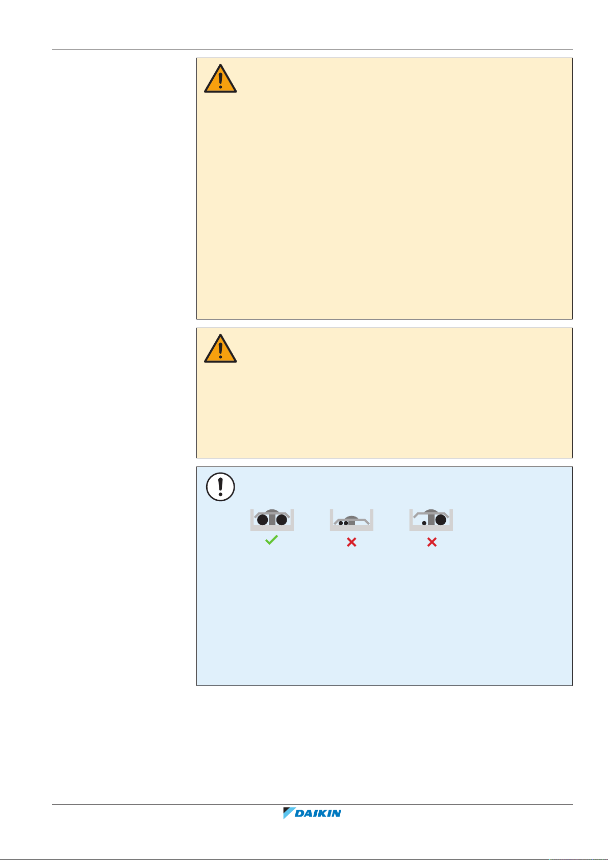
NOTICE
Precautions when laying power wiring:
▪ Do NOT connect wiring of different thicknesses to the power terminal block (slack
in the power wiring may cause abnormal heat).
▪ When connecting wiring which is the same thickness, do as shown in the figure
above.
▪ For wiring, use the designated power wire and connect firmly, then secure to
prevent outside pressure being exerted on the terminal board.
▪ Use an appropriate screwdriver for tightening the terminal screws. A screwdriver
with a small head will damage the head and make proper tightening impossible.
▪ Over-tightening the terminal screws may break them.
ERGA04~08EAV3(A) + EHVH04+08SU18+23EA6V
Daikin Altherma 3 R F
4P629090-1 – 2020.08
Install power cables at least 1 m away from televisions or radios to prevent
interference. Depending on the radio waves, a distance of 1 m may not be
sufficient.
Installer reference guide
13

2 | General safety precautions
WARNING
▪ After finishing the electrical work, confirm that each electrical component and
terminal inside the electrical components box is connected securely.
▪ Make sure all covers are closed before starting up the unit.
NOTICE
Only applicable if the power supply is three‑phase, and the compressor has an ON/
OFF starting method.
If there exists the possibility of reversed phase after a momentary black out and the
power goes on and off while the product is operating, attach a reversed phase
protection circuit locally. Running the product in reversed phase can break the
compressor and other parts.
Installer reference guide
14
ERGA04~08EAV3(A) + EHVH04+08SU18+23EA6V
Daikin Altherma 3 R F
4P629090-1 – 2020.08
3 | Specific installer safety instructions
3 Specific installer safety instructions
Always observe the following safety instructions and regulations.
Application guidelines (see
CAUTION
If there is more than one leaving water zone, ALWAYS install a mixing valve station in
the main zone to decrease (in heating)/increase (in cooling) the leaving water
temperature when the additional zone has demand.
Installation site (see
"7.1Preparing the installation site"[455]
WARNING
The appliance shall be stored in a room without continuously operating ignition
sources (example: open flames, an operating gas appliance or an operating electric
heater).
WARNING
DO NOT reuse refrigerant piping that has been used with any other refrigerant.
Replace the refrigerant pipes or clean thoroughly.
WARNING
▪ Do NOT pierce or burn.
▪ Do NOT use means to accelerate the defrosting process or to clean the
equipment, other than those recommended by the manufacturer.
▪ Be aware that R32 refrigerant does NOT contain an odour.
"6Application guidelines"[430]
)
)
WARNING
The appliance shall be stored so as to prevent mechanical damage and in a wellventilated room without continuously operating ignition sources (example: open
flames, an operating gas appliance or an operating electric heater) and have a room
size as specified below.
Charging refrigerant (see
WARNING
If the total refrigerant charge in the system is ≥1.84 kg (i.e. if the piping length is
≥27 m), you need to comply with the minimum floor area requirements for the
indoor unit. For more information, see "7.1.3Installation site requirements of the
indoor unit"[459].
CAUTION
To avoid compressor breakdown, do NOT charge more than the specified amount of
refrigerant.
WARNING
▪ Only use R32 as refrigerant. Other substances may cause explosions and
accidents.
▪ R32 contains fluorinated greenhouse gases. Its global warming potential (GWP)
value is 675. Do NOT vent these gases into the atmosphere.
▪ When charging refrigerant, ALWAYS use protective gloves and safety glasses.
"8.5Charging refrigerant"[493]
)
ERGA04~08EAV3(A) + EHVH04+08SU18+23EA6V
Daikin Altherma 3 R F
4P629090-1 – 2020.08
Installer reference guide
15
3 | Specific installer safety instructions
a
Electrical installation (see
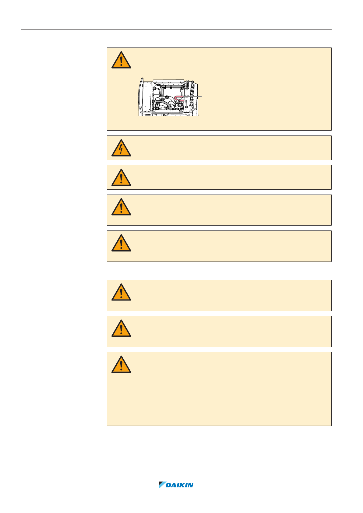
WARNING
Make sure that the electrical wiring does NOT touch the refrigerant gas pipe, which
can be very hot.
a Refrigerant gas pipe
DANGER: RISK OF ELECTROCUTION
WARNING
ALWAYS use multicore cable for power supply cables.
CAUTION
To guarantee the unit is completely earthed, always connect the backup heater
power supply and the earth cable.
"9Electrical installation"[4103]
)
WARNING
The backup heater MUST have a dedicated power supply and MUST be protected by
the safety devices required by the applicable legislation.
Configuration (see
CAUTION
The disinfection function settings MUST be configured by the installer according to
the applicable legislation.
CAUTION
Be sure that the disinfection function start time [5.7.3] with defined duration [5.7.5]
is NOT interrupted by possible domestic hot water demand.
WARNING
Be aware that the domestic hot water temperature at the hot water tap will be equal
to the value selected in field setting [2-03] after a disinfection operation.
When the high domestic hot water temperature can be a potential risk for human
injuries, a mixing valve (field supply) shall be installed at the hot water outlet
connection of the domestic hot water tank. This mixing valve shall secure that the
hot water temperature at the hot water tap never rise above a set maximum value.
This maximum allowable hot water temperature shall be selected according to the
applicable legislation.
"10Configuration"[4131]
)
Installer reference guide
16
ERGA04~08EAV3(A) + EHVH04+08SU18+23EA6V
Daikin Altherma 3 R F
4P629090-1 – 2020.08
3 | Specific installer safety instructions
CAUTION
Make sure to observe all rules mentioned in application guideline 5 when bivalent
operation function is enabled.
Daikin shall NOT be held liable for any damage resulting from failure to observe this
rule.
Maintenance and service (see
CAUTION
Water coming out of the valve may be very hot.
WARNING
If the internal wiring is damaged, it has to be replaced by the manufacturer, its
service agent or similarly qualified persons.
CAUTION
Although the water circuit is drained, some water may be spilled when removing the
magnetic filter/dirt separator from the filter housing. ALWAYS clean up spilled water.
CAUTION
To protect the piping connected to the magnetic filter/dirt separator from damage it
is recommended to perform this procedure with the magnetic filter/dirt separator
removed from the unit.
CAUTION
Opening the magnetic filter/dirt separator is ONLY required in case of severe issues.
Preferably this action is never to be done during the complete lifetime of the
magnetic filter/dirt separator.
"13Maintenance and service"[4226]
)
CAUTION
Check the condition of the O-rings and replace if needed. Apply water to the O-rings
before installation.
CAUTION
Make sure to open the valve (if equipped) towards the expansion vessel, otherwise
the overpressure will be generated.
Troubleshooting (see
WARNING
Prevent hazards due to inadvertent resetting of the thermal cut-out: power to this
appliance MUST NOT be supplied through an external switching device, such as a
timer, or connected to a circuit that is regularly turned ON and OFF by the utility.
"14Troubleshooting"[4235]
)
ERGA04~08EAV3(A) + EHVH04+08SU18+23EA6V
Daikin Altherma 3 R F
4P629090-1 – 2020.08
Installer reference guide
17
3 | Specific installer safety instructions
WARNING
▪ When carrying out an inspection on the switch box of the unit, ALWAYS make
sure that the unit is disconnected from the mains. Turn off the respective circuit
breaker.
▪ When a safety device was activated, stop the unit and find out why the safety
device was activated before resetting it. NEVER shunt safety devices or change
their values to a value other than the factory default setting. If you are unable to
find the cause of the problem, call your dealer.
WARNING
Air purging heat emitters or collectors. Before you purge air from heat emitters or
collectors, check if or is displayed on the home screen of the user interface.
▪ If not, you can purge air immediately.
▪ If yes, make sure that the room where you want to purge air is sufficiently
ventilated. Reason: Refrigerant might leak into the water circuit, and
subsequently into the room when you purge air from the heat emitters or
collectors.
Disposal (see
"15Disposal"[4246]
)
DANGER: RISK OF EXPLOSION
Pump down – Refrigerant leakage. If you want to pump down the system, and there
is a leak in the refrigerant circuit:
▪ Do NOT use the unit's automatic pump down function, with which you can collect
all refrigerant from the system into the outdoor unit. Possible consequence: Selfcombustion and explosion of the compressor because of air going into the
operating compressor.
▪ Use a separate recovery system so that the unit's compressor does NOT have to
operate.
3.1 Instructions for equipment using R32 refrigerant
WARNING: FLAMMABLE MATERIAL
The refrigerant inside this unit is mildly flammable.
WARNING
▪ Do NOT pierce or burn.
▪ Do NOT use means to accelerate the defrosting process or to clean the
equipment, other than those recommended by the manufacturer.
▪ Be aware that R32 refrigerant does NOT contain an odour.
Installer reference guide
18
WARNING
The appliance shall be stored so as to prevent mechanical damage and in a wellventilated room without continuously operating ignition sources (example: open
flames, an operating gas appliance or an operating electric heater) and have a room
size as specified below.
ERGA04~08EAV3(A) + EHVH04+08SU18+23EA6V
Daikin Altherma 3 R F
4P629090-1 – 2020.08
3 | Specific installer safety instructions
WARNING
Make sure installation, servicing, maintenance and repair comply with instructions
from Daikin and with applicable legislation (for example national gas regulation) and
are executed only by authorised persons.
WARNING
If one or more rooms are connected to the unit using a duct system, make sure:
▪ there are no operating ignition sources (example: open flames, an operating gas
appliance or an operating electric heater) in case the floor area is less than the
minimum floor area A (m²).
▪ no auxiliary devices, which may be a potential ignition source, are installed in the
duct work (example: hot surfaces with a temperature exceeding 700°C and
electric switching device);
▪ only auxiliary devices approved by the manufacturer are used in the duct work;
▪ air inlet AND outlet are connected directly to the same room by ducting. Do NOT
use spaces such as a false ceiling as a duct for the air inlet or outlet.
NOTICE
▪ Precautions shall be taken to avoid excessive vibration or pulsation to
refrigeration piping.
▪ Protection devices, piping and fittings shall be protected as far as possible against
adverse environmental effects.
▪ Provision shall be made for expansion and contraction of long runs of piping.
▪ Piping in refrigerating systems shall be designed and installed such as to minimise
the likelihood of hydraulic shock damaging the system.
▪ The indoor equipment and pipes shall be securely mounted and guarded such
that accidental rupture of equipment or pipes cannot occur from events such as
moving furniture or reconstruction activities.
CAUTION
Do NOT use potential sources of ignition in searching for or detection of refrigerant
leaks.
NOTICE
▪ Do NOT re-use joints and copper gaskets which have been used already.
▪ Joints made in installation between parts of refrigerant system shall be accessible
for maintenance purposes.
ERGA04~08EAV3(A) + EHVH04+08SU18+23EA6V
Daikin Altherma 3 R F
4P629090-1 – 2020.08
Installer reference guide
19
4 | About the box
1 2
4 About the box
In this chapter
4.1 Overview: About the box
4.1 Overview: About the box........................................................................................................................................................ 20
4.2 Outdoor unit ........................................................................................................................................................................... 20
4.2.1 To unpack the outdoor unit ................................................................................................................................... 20
4.2.2 To handle the outdoor unit.................................................................................................................................... 21
4.2.3 To remove the accessories from the outdoor unit ............................................................................................... 21
4.3 Indoor unit .............................................................................................................................................................................. 22
4.3.1 To unpack the indoor unit...................................................................................................................................... 22
4.3.2 To remove the accessories from the indoor unit .................................................................................................. 22
4.3.3 To handle the indoor unit ...................................................................................................................................... 23
4.4 Domestic hot water tank kit ................................................................................................................................................... 23
4.4.1 To remove the accessories from the domestic hot water tank kit ....................................................................... 23
4.5 Checklist for the required DHW accessories.......................................................................................................................... 23
This chapter describes what you have to do after the boxes with the outdoor and
indoor unit are delivered on-site.
4.2 Outdoor unit
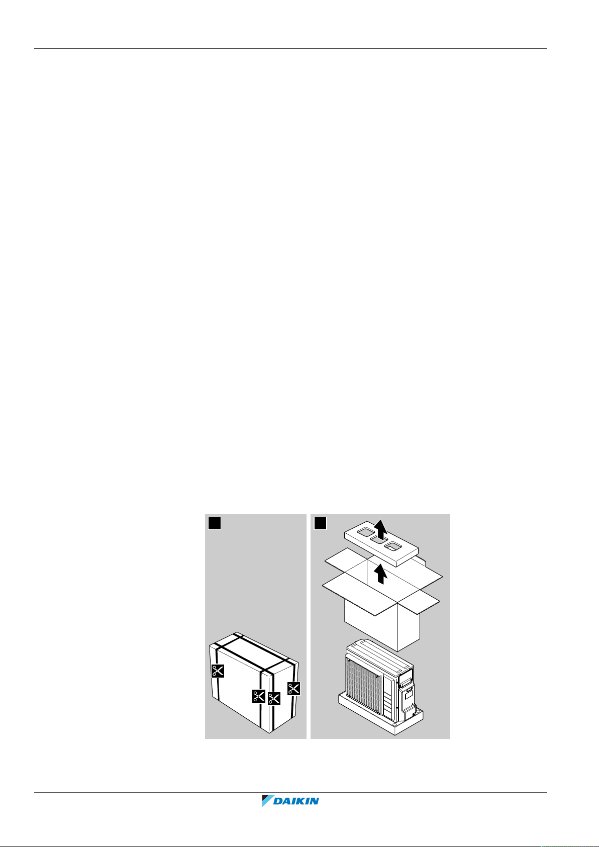
4.2.1 To unpack the outdoor unit
Keep the following in mind:
▪ At delivery, the unit MUST be checked for damage. Any damage MUST be
reported immediately to the claims agent of the carrier.
▪ Bring the packed unit as close as possible to its final installation position to
prevent damage during transport.
▪ Prepare the path along which you want to bring the unit inside in advance.
Installer reference guide
20
ERGA04~08EAV3(A) + EHVH04+08SU18+23EA6V
Daikin Altherma 3 R F
4P629090-1 – 2020.08
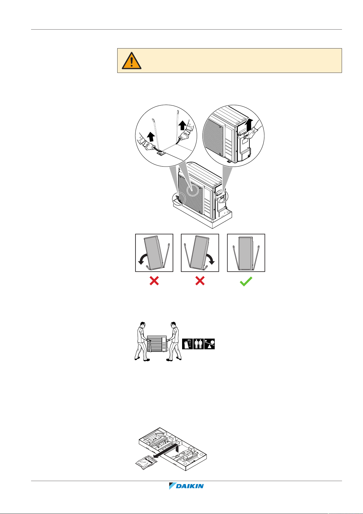
4.2.2 To handle the outdoor unit
2
1
1
CAUTION
To avoid injury, do NOT touch the air inlet or aluminium fins of the unit.
1 Handle the unit using the sling to the left and the handle to the right. Pull up
both sides of the sling at the same time to prevent disconnection of the sling
from the unit.
4 | About the box
2 While handling the unit:
▪ Keep both sides of the sling level.
▪ Keep your back straight.
3 After mounting the unit, remove the sling from the unit by pulling 1 side of the
sling.
4.2.3 To remove the accessories from the outdoor unit
1 Lift the outdoor unit. See "4.2.2To handle the outdoor unit"[421].
2 Remove the accessories at the bottom of the package.
ERGA04~08EAV3(A) + EHVH04+08SU18+23EA6V
Daikin Altherma 3 R F
4P629090-1 – 2020.08
Installer reference guide
21
4 | About the box
ENERG
IJAY
IAIE
ENERG
IJAY
IAIE
1×1× 1× 1× 2× 1×
da b c e f
1 2
8×
1×
4×
8×
1×
1× 1×
4× 1×
1× 1× 1× 1×
a b c d e
j k lf g h i
4.3 Indoor unit
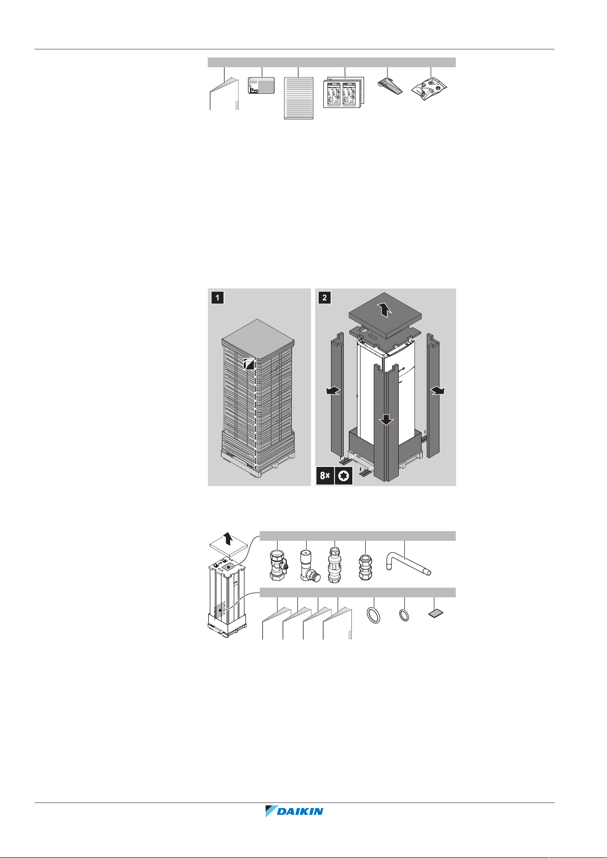
4.3.1 To unpack the indoor unit
a Outdoor unit installation manual
b Fluorinated greenhouse gases label
c Multilingual fluorinated greenhouse gases label
d Energy label
e Unit mounting plate
f Bolts, nuts, washers, spring washers and wire clamp
4.3.2 To remove the accessories from the indoor unit
Installer reference guide
22
a Shut-off valves for water circuit
b Overpressure bypass valve
c Tundish (to mount onto the pressure relief valve discharge pipe)
d Brass compression coupler
e Discharge pipe (for pressure relief valve)
f General safety precautions
g Addendum book for optional equipment
h Indoor unit installation manual
i Operation manual
j Sealing rings for shut-off valves (space heating water circuit)
k Sealing rings for field-supplied shut-off valves (domestic hot water circuit)
l Sealing tape for low voltage wiring intake
ERGA04~08EAV3(A) + EHVH04+08SU18+23EA6V
Daikin Altherma 3 R F
4P629090-1 – 2020.08
4.3.3 To handle the indoor unit
b
a a
b
d
b
a
c
e
g
f
Use the handles at the back and at the bottom to carry the unit.
a Handles at the back of the unit
b Handles at the bottom of the unit. Carefully tilt the unit to the back so that the
handles become visible.
4.4 Domestic hot water tank kit
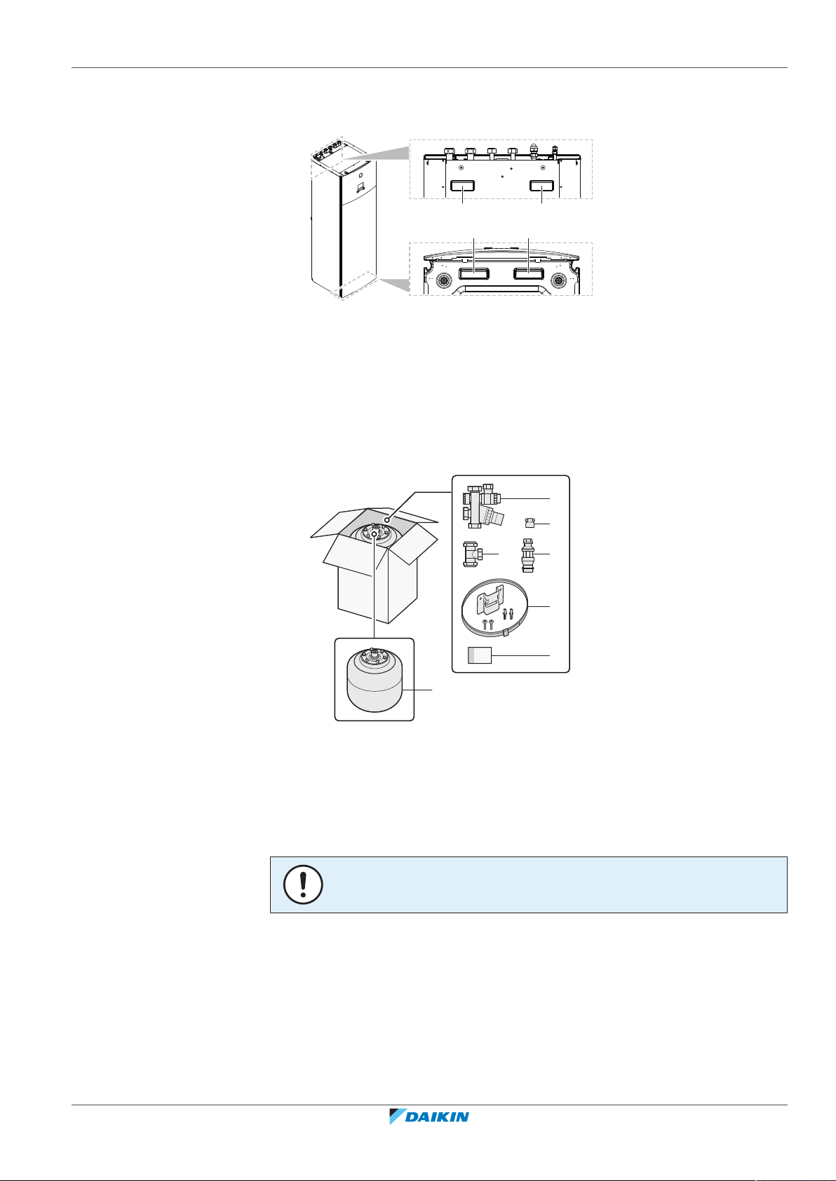
4.4.1 To remove the accessories from the domestic hot water tank kit
4 | About the box
4.5 Checklist for the required DHW accessories
ERGA04~08EAV3(A) + EHVH04+08SU18+23EA6V
Daikin Altherma 3 R F
4P629090-1 – 2020.08
a Pressure reducing valve/pressure relief valve combination. Water inlet and water
outlet 22mm connection, discharge piping connection 15mm
b Adaptor 22mm×3/4" Female BSP
c T-piece 22mm×22mm×22mm
d Tundish 15mm inlet, 22mm outlet
e Wall mounting set for expansion vessel
f Instruction sheet
g Expansion vessel of 18l – 3/4" Male BSP
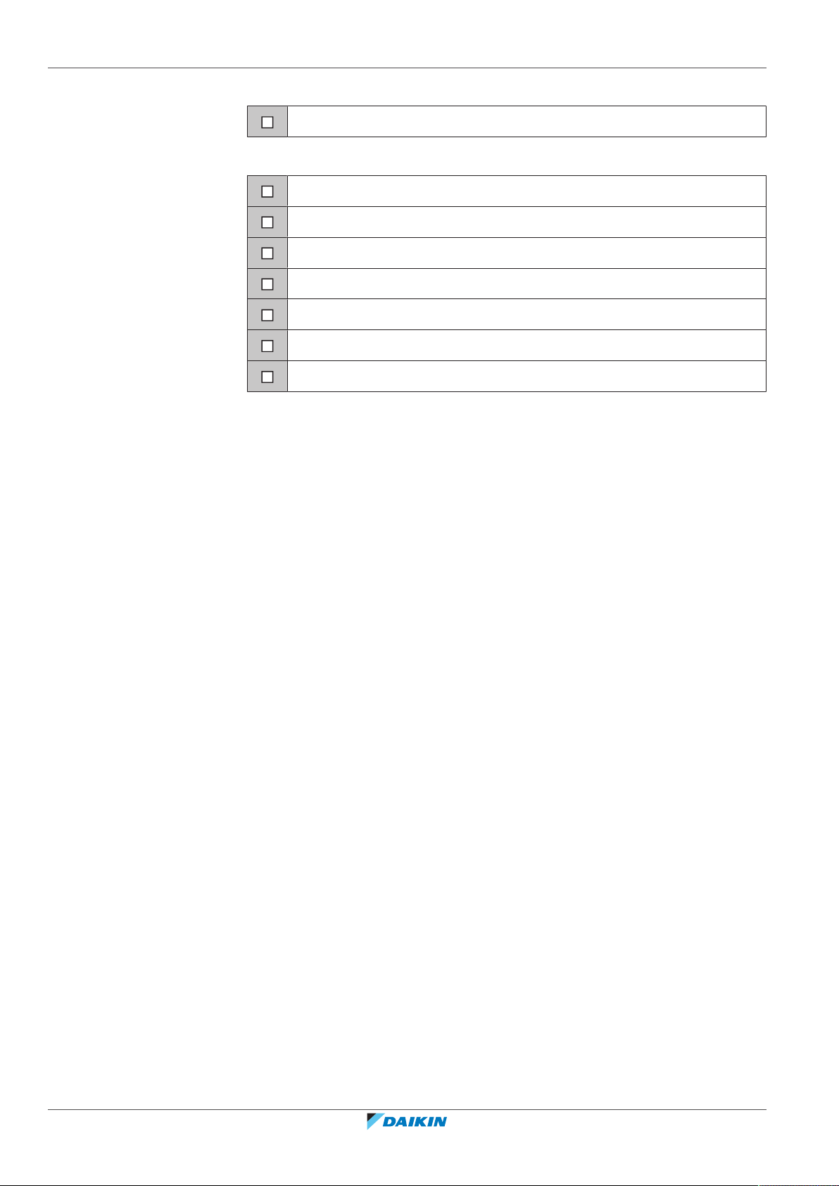
NOTICE
All piping MUST be installed according to section G3 of the Building Regulations.
For installation compliant with section G3 of the Building Regulations, you must
verify that the following accessories are present.
Installer reference guide
23
4 | About the box
Delivered with indoor unit:
Tundish 15mm inlet, 22mm outlet
Delivered with domestic hot water tank kit:
Pressure reducing valve/pressure relief valve combination
Adaptor 22mm×3/4" Female BSP
T-piece 22mm×22mm×22mm
Tundish 15mm inlet, 22mm outlet
Wall mounting set for expansion vessel
Instruction sheet
Expansion vessel of 18l – 3/4" Male BSP
Installer reference guide
24
ERGA04~08EAV3(A) + EHVH04+08SU18+23EA6V
Daikin Altherma 3 R F
4P629090-1 – 2020.08
5 About the units and options
In this chapter
5.1 Overview: About the units and options ................................................................................................................................. 25
5.2 Identification........................................................................................................................................................................... 25
5.2.1 Identification label: Outdoor unit .......................................................................................................................... 25
5.2.2 Identification label: Indoor unit ............................................................................................................................. 26
5.3 Combining units and options.................................................................................................................................................. 26
5.3.1 Possible options for the outdoor unit.................................................................................................................... 26
5.3.2 Possible options for the indoor unit ...................................................................................................................... 27
5.1 Overview: About the units and options
This chapter contains information about:
▪ Identifying the outdoor unit
▪ Identifying the indoor unit
▪ Combining the outdoor unit with options
▪ Combining the indoor unit with options
5 | About the units and options
5.2 Identification
NOTICE
When installing or servicing several units at the same time, make sure NOT to switch
the service panels between different models.
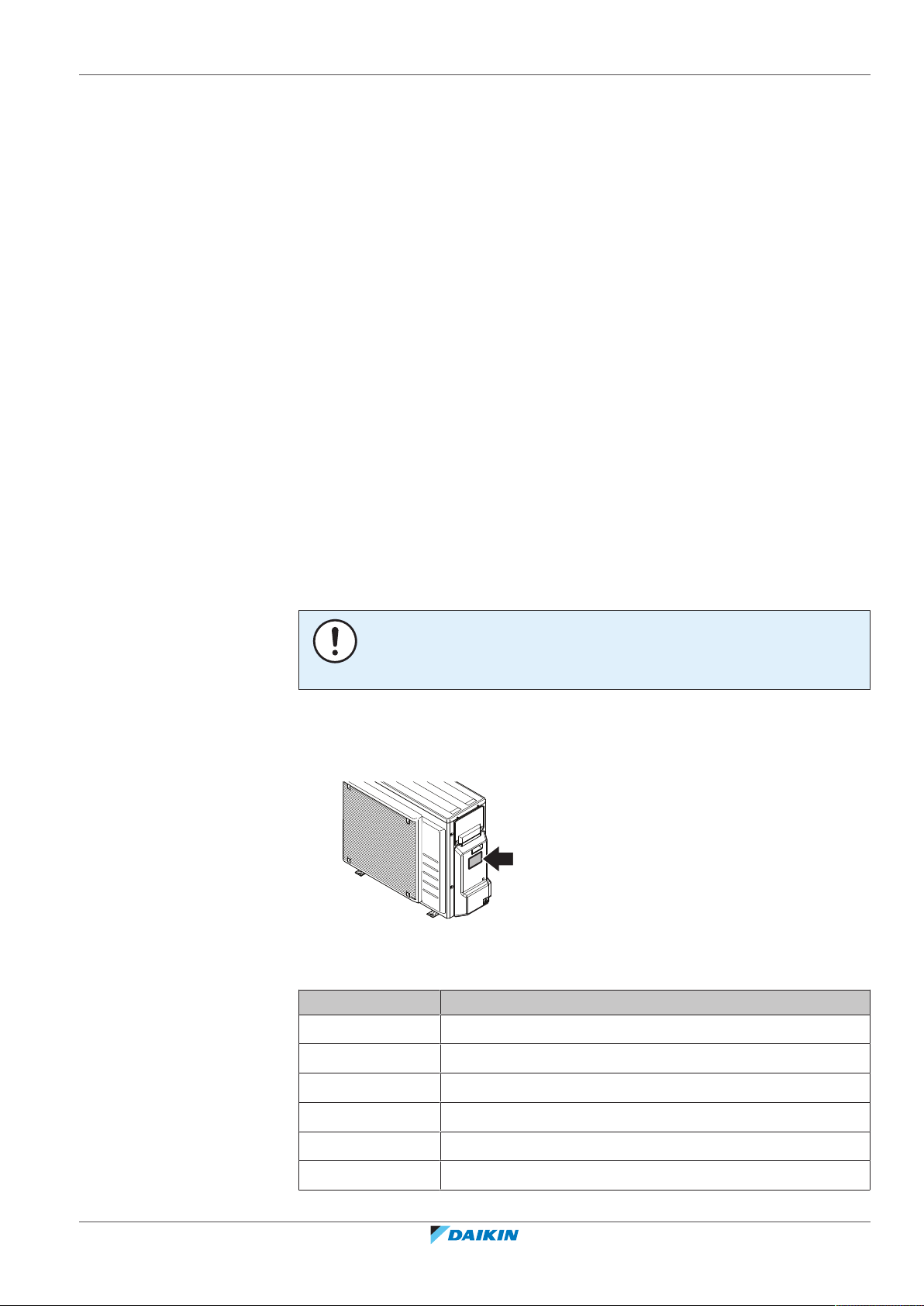
5.2.1 Identification label: Outdoor unit
Location
Model identification
Example: ERGA06DAV3 A
Code Explanation
ERGA04~08EAV3(A) + EHVH04+08SU18+23EA6V
Daikin Altherma 3 R F
4P629090-1 – 2020.08
ER European split outdoor pair heat pump
G Medium water temperature – ambient zone: −10~−20°C
A Refrigerant R32
06 Capacity class
DA Model series
V3 Power supply
Installer reference guide
25
5 | About the units and options
A A=Austrian model
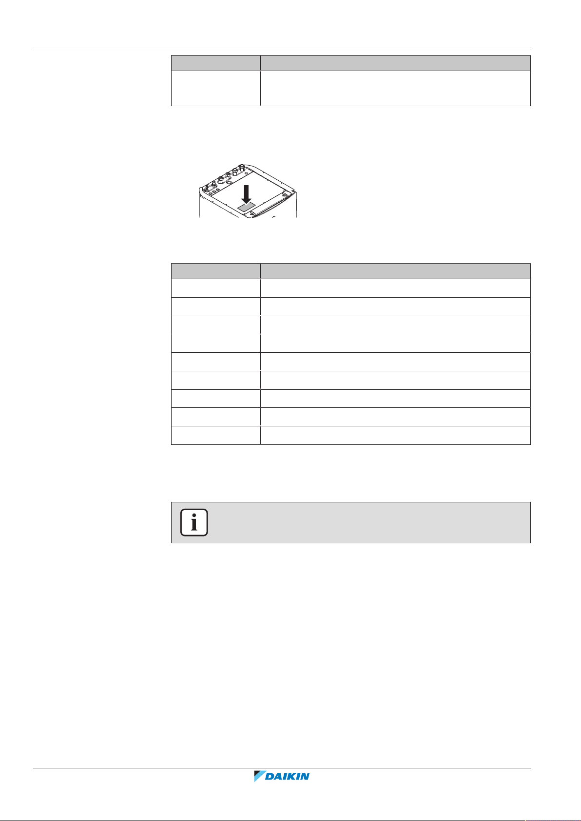
5.2.2 Identification label: Indoor unit
Location
Model identification
Example: EHVH08SU23EA6V
E European model
HV Floor-standing indoor unit with integrated tank
Code Explanation
[—]=Non-Austrian model
Code Description
H Heating only
08 Capacity class
S Integrated tank material: Stainless steel
U UK model
23 Integrated tank volume
EA Model series
6V Backup heater model
5.3 Combining units and options
INFORMATION
Certain options might not be available in your country.
5.3.1 Possible options for the outdoor unit
Drain pan kit (EKDP008D)
The drain pan kit is required to gather the drain from the outdoor unit. The drain
pan kit consists of:
Installer reference guide
26
▪ Drain pan
▪ Installation brackets
For installation instructions, see the installation manual of the drain pan.
Drain pan heater (EKDPH008CA)
The drain pan heater is required to avoid freezing-up of the drain pan.
It is recommended to install this option in colder regions with possible low ambient
temperatures or heavy snowfall.
For installation instructions, see the installation manual of the drain pan heater.
ERGA04~08EAV3(A) + EHVH04+08SU18+23EA6V
Daikin Altherma 3 R F
4P629090-1 – 2020.08

5 | About the units and options
U-beams (EKFT008D)
The U-beams are installation brackets on which the outdoor unit can be installed.
It is recommended to install this option in colder regions with possible low ambient
temperatures or heavy snowfall.
For installation instructions, see the installation manual of the outdoor unit.
Low sound cover (EKLN08A1)
In sound sensitive areas (e.g. near a bedroom), you can install the low sound cover
to decrease the operation noise of the outdoor unit.
You can install the low sound cover:
▪ On mounting feet to the ground. This must withstand 200kg.
▪ On brackets to the wall. This must withstand 200kg.
If you install the low sound cover, you also need to install one of the following
options:
▪ Recommended: Drain pan kit (with or without drain pan heater)
▪ U-beams
For installation instructions, see the installation manual of the low sound cover.
5.3.2 Possible options for the indoor unit
User interface used as room thermostat (BRC1HHDA)
▪ The user interface used as room thermostat can only be used in combination
with the user interface connected to the indoor unit.
▪ The user interface used as room thermostat needs to be installed in the room
that you want to control.
For installation instructions, see the installation and operation manual of the user
interface used as room thermostat.
Room thermostat (EKRTWA, EKRTR1)
You can connect an optional room thermostat to the indoor unit. This thermostat
can either be wired (EKRTWA) or wireless (EKRTR1).
For installation instructions, see the installation manual of the room thermostat
and addendum book for optional equipment.
Remote sensor for wireless thermostat (EKRTETS)
You can use the remote indoor temperature sensor (EKRTETS) only in combination
with the wireless thermostat (EKRTR1).
For installation instructions, see the installation manual of the room thermostat
and the addendum book for optional equipment.
ERGA04~08EAV3(A) + EHVH04+08SU18+23EA6V
Daikin Altherma 3 R F
4P629090-1 – 2020.08
Digital I/O PCB (EKRP1HBAA)
The digital I/O PCB is required to provide following signals:
▪ Alarm output
▪ Space heating/cooling On/OFF output
▪ Changeover to external heat source
For installation instructions, see the installation manual of the digital I/O PCB and
addendum book for optional equipment.
Installer reference guide
27
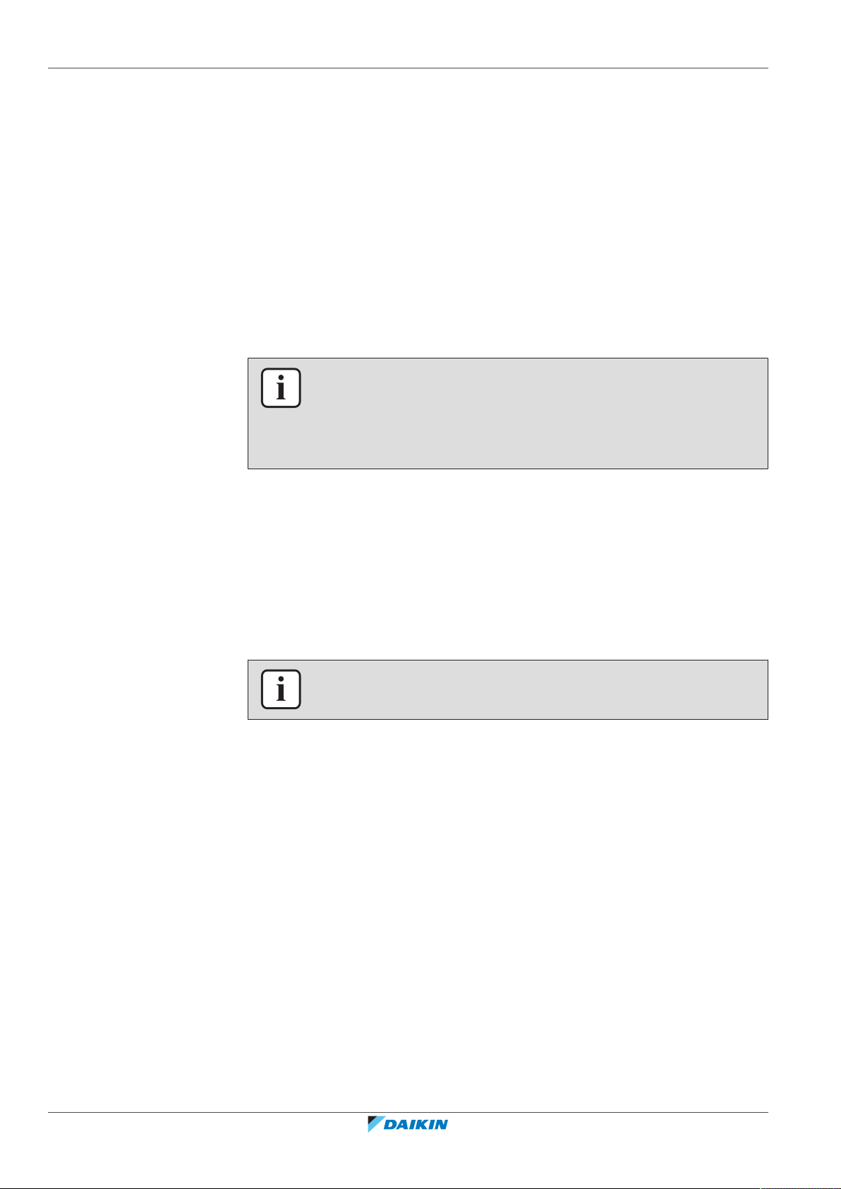
5 | About the units and options
Demand PCB (EKRP1AHTA)
To enable the power saving consumption control by digital inputs you must install
the demand PCB.
For installation instructions, see the installation manual of the demand PCB and
addendum book for optional equipment.
Remote indoor sensor (KRCS01-1)
By default the internal user interface sensor will be used as room temperature
sensor.
As an option the remote indoor sensor can be installed to measure the room
temperature on another location.
For installation instructions, see the installation manual of the remote indoor
sensor and addendum book for optional equipment.
INFORMATION
▪ The remote indoor sensor can only be used in case the user interface is
configured with room thermostat functionality.
▪ You can only connect either the remote indoor sensor or the remote outdoor
sensor.
Remote outdoor sensor (EKRSCA1)
By default the sensor inside the outdoor unit will be used to measure the outdoor
temperature.
As an option the remote outdoor sensor can be installed to measure the outdoor
temperature on another location (e.g. to avoid direct sunlight) to have an
improved system behaviour.
For installation instructions, see the installation manual of the remote outdoor
sensor and the addendum book for optional equipment.
INFORMATION
You can only connect either the remote indoor sensor or the remote outdoor sensor.
PC cable (EKPCCAB4)
The PC cable makes a connection between the switch box of the indoor unit and a
PC. It gives the possibility to update the software of the indoor unit.
For installation instructions, see the installation manual of the PC cable.
Pipe bend kit (EKHVTC)
When the indoor unit is installed in a place with limited space, a pipe bend kit can
be installed to facilitate the connection to the refrigerant liquid and gas
connections of the indoor unit.
Installer reference guide
28
For installation instructions, see the instruction sheet of the pipe bend kit.
Heat pump convector (FWXV)
For providing space heating/cooling, it is possible to use heat pump convectors
(FWXV).
For installation instructions, see the installation manual of the heat pump
convectors, and the addendum book for optional equipment.
ERGA04~08EAV3(A) + EHVH04+08SU18+23EA6V
Daikin Altherma 3 R F
4P629090-1 – 2020.08

5 | About the units and options
LAN adapter for smartphone control + Smart Grid applications (BRP069A61)
You can install this LAN adapter to:
▪ Control the system via a smartphone app.
▪ Use the system in various Smart Grid applications.
For installation instructions, see the installation manual of the LAN adapter.
LAN adapter for smartphone control (BRP069A62)
You can install this LAN adapter to control the system via a smartphone app.
For installation instructions, see the installation manual of the LAN adapter.
Conversion kit (EKHVCONV4)
Use the connection kit to convert a heating only model to a reversible model.
For installation instructions, see the installation manual of the conversion kit.
WLAN adapter module (BRP069A71)
A WLAN cartridge (to be plugged into the MMI) is delivered as indoor unit
accessory. Alternatively (e.g. in case of weak signal strength), you can install the
optional wireless LAN adapter module BRP069A71.
For installation instructions, see the installation manual of the WLAN adapter
module and the addendum book for optional equipment.
Smart grid relay kit (EKRELSG)
The installation of the optional Smart grid relay kit is required in case of high
voltage Smart grid contacts (EKRELSG).
For installation instructions, see "9.3.11To connect a Smart Grid"[4125].
ERGA04~08EAV3(A) + EHVH04+08SU18+23EA6V
Daikin Altherma 3 R F
4P629090-1 – 2020.08
Installer reference guide
29
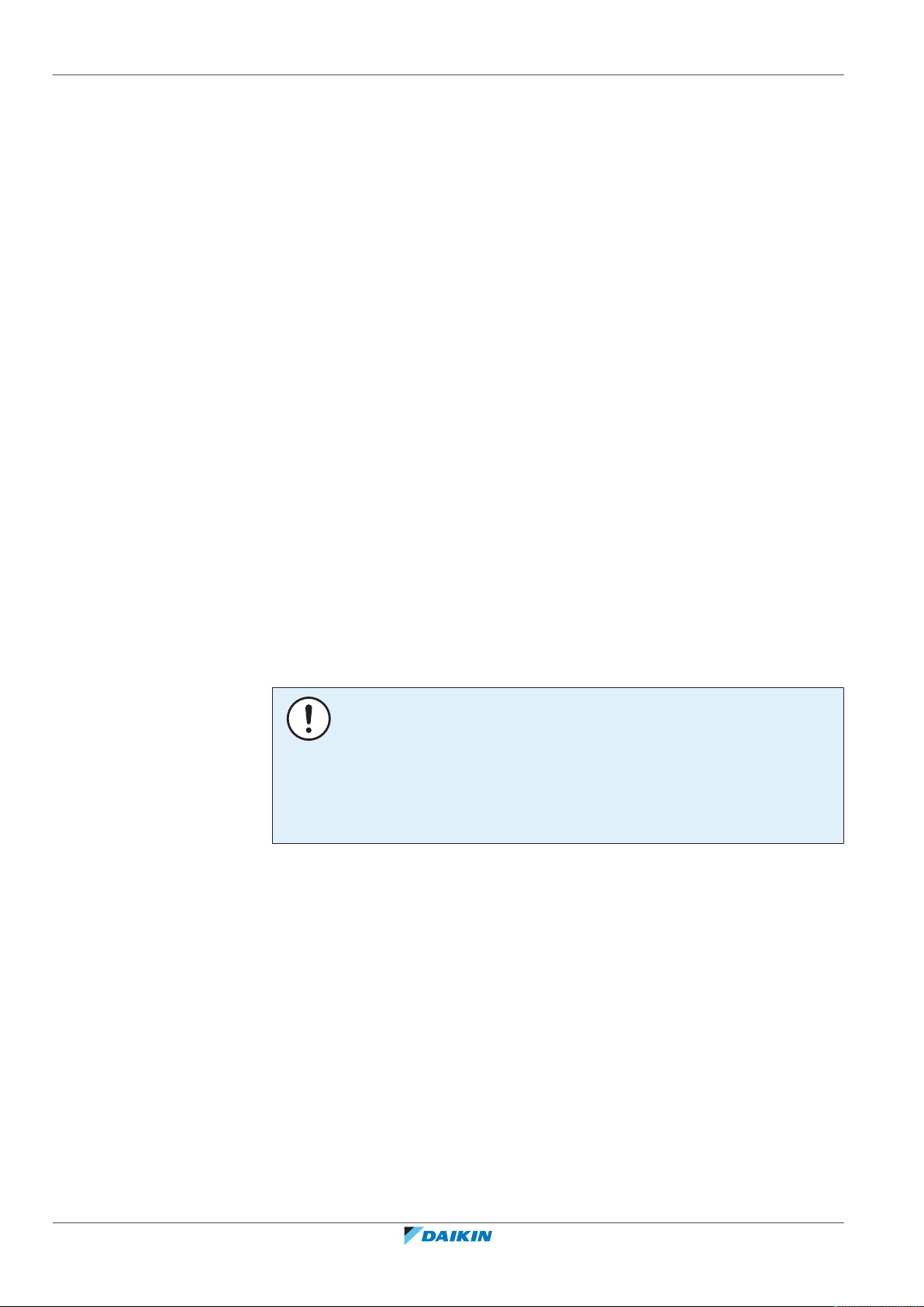
6 | Application guidelines
6 Application guidelines
In this chapter
6.1 Overview: Application guidelines........................................................................................................................................... 30
6.2 Setting up the space heating/cooling system ........................................................................................................................ 30
6.2.1 Single room............................................................................................................................................................. 31
6.2.2 Multiple rooms – OneLWT zone ........................................................................................................................... 35
6.2.3 Multiple rooms – TwoLWT zones ......................................................................................................................... 39
6.3 Setting up an auxiliary heat source for space heating........................................................................................................... 41
6.4 Setting up the domestic hot water tank ................................................................................................................................ 44
6.4.1 System layout – Integrated DHW tank .................................................................................................................. 44
6.4.2 Selecting the volume and desired temperature for the DHW tank ...................................................................... 44
6.4.3 Setup and configuration – DHW tank .................................................................................................................... 46
6.4.4 DHW pump for instant hot water .......................................................................................................................... 46
6.4.5 DHW pump for disinfection ................................................................................................................................... 47
6.5 Setting up the energy metering ............................................................................................................................................. 47
6.5.1 Produced heat ........................................................................................................................................................ 47
6.5.2 Consumed energy .................................................................................................................................................. 48
6.5.3 Normal kWh rate power supply............................................................................................................................. 48
6.5.4 Preferential kWh rate power supply...................................................................................................................... 50
6.6 Setting up the power consumption control........................................................................................................................... 51
6.6.1 Permanent power limitation.................................................................................................................................. 51
6.6.2 Power limitation activated by digital inputs .......................................................................................................... 51
6.6.3 Power limitation process ....................................................................................................................................... 53
6.7 Setting up an external temperature sensor........................................................................................................................... 53
6.1 Overview: Application guidelines
The purpose of the application guidelines is to give a glance of the possibilities of
the heatpump system.
NOTICE
▪ The illustrations in the application guidelines are meant for reference only, and
are NOT to be used as detailed hydraulic diagrams. The detailed hydraulic
dimensioning and balancing are NOT shown, and are the responsibility of the
installer.
▪ For more information about the configuration settings to optimize heat pump
operation, see "10Configuration"[4131].
This chapter contains application guidelines for:
▪ Setting up the space heating/cooling system
▪ Setting up an auxiliary heat source for space heating
▪ Setting up the domestic hot water tank
▪ Setting up the energy metering
▪ Setting up the power consumption control
▪ Setting up an external temperature sensor
6.2 Setting up the space heating/cooling system
Installer reference guide
30
The heat pump system supplies leaving water to heat emitters in one or more
rooms.
ERGA04~08EAV3(A) + EHVH04+08SU18+23EA6V
Daikin Altherma 3 R F
4P629090-1 – 2020.08
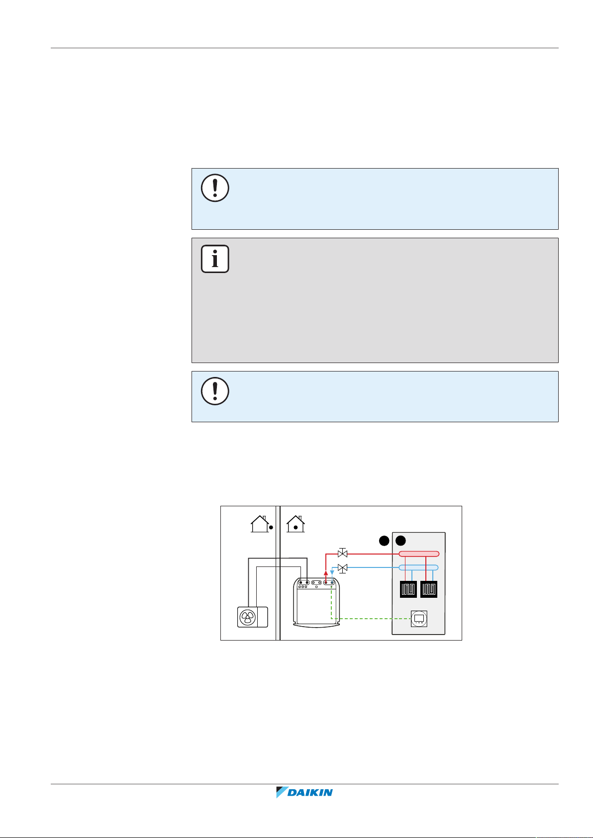
6 | Application guidelines
A
B
a
Because the system offers a wide flexibility to control the temperature in each
room, you need to answer the following questions first:
▪ How many rooms are heated or cooled by the heatpump system?
▪ Which heat emitter types are used in each room and what is their design leaving
water temperature?
Once the space heating/cooling requirements are clear, we recommend to follow
the setup guidelines below.
NOTICE
If an external room thermostat is used, the external room thermostat will control the
room frost protection. However, the room frost protection is only possible if [C.2]
Space heating/cooling=On.
INFORMATION
In case an external room thermostat is used and room frost protection needs to be
guaranteed in all conditions, then you have to set Emergency [9.5.1] to one of the
following:
▪ Automatic
▪ auto SH reduced/DHW on
▪ auto SH reduced/DHW off
▪ auto SH normal/DHW off
6.2.1 Single room
Underfloor heating or radiators – Wired room thermostat
NOTICE
An overpressure bypass valve can be integrated in the system. Keep in mind that this
valve might not be shown on the illustrations.
Setup
A Main leaving water temperature zone
B One single room
a Dedicated Human Comfort Interface (BRC1HHDA used as room thermostat)
▪ The underfloor heating or radiators are directly connected to the indoor unit.
ERGA04~08EAV3(A) + EHVH04+08SU18+23EA6V
Daikin Altherma 3 R F
4P629090-1 – 2020.08
▪ The room temperature is controlled by the dedicated Human Comfort Interface
(BRC1HHDA used as room thermostat).
Installer reference guide
31

6 | Application guidelines
A
B
b
a
Configuration
Setting Value
Unit temperature control:
▪ #: [2.9]
2 (Room thermostat): Unit operation
is decided based on the ambient
temperature of the user interface.
▪ Code: [C-07]
Number of water temperature zones:
0 (Single zone): Main
▪ #: [4.4]
▪ Code: [7-02]
Benefits
▪ Highest comfort and efficiency. The smart room thermostat functionality can
decrease or increase the desired leaving water temperature based on the actual
room temperature (modulation). This results in:
- Stable room temperature matching the desired temperature (higher comfort)
- Less ON/OFF cycles (more quiet, higher comfort and higher efficiency)
- Lowest possible leaving water temperature (higher efficiency)
▪ Easy. You can easily set the desired room temperature via the user interface:
- For your daily needs, you can use preset values and schedules.
- To deviate from your daily needs, you can temporarily overrule the preset
values and schedules, or use the holiday mode.
Underfloor heating or radiators – Wireless room thermostat
Setup
A Main leaving water temperature zone
B One single room
a Receiver for wireless external room thermostat
b Wireless external room thermostat
▪ The underfloor heating or radiators are directly connected to the indoor unit.
▪ The room temperature is controlled by the wireless external room thermostat
(optional equipment EKRTR1).
Configuration
Installer reference guide
32
Setting Value
Unit temperature control:
▪ #: [2.9]
▪ Code: [C-07]
1 (External room thermostat):
Unit operation is decided by the
external thermostat.
ERGA04~08EAV3(A) + EHVH04+08SU18+23EA6V
Daikin Altherma 3 R F
4P629090-1 – 2020.08

6 | Application guidelines
a
A
B
Setting Value
Number of water temperature zones:
▪ #: [4.4]
▪ Code: [7-02]
External room thermostat for the main
zone:
▪ #: [2.A]
▪ Code: [C-05]
Benefits
▪ Wireless. The Daikin external room thermostat is available in a wireless version.
▪ Efficiency. Although the external room thermostat only sends ON/OFF signals, it
is specifically designed for the heatpump system.
▪ Comfort. In case of underfloor heating, the wireless external room thermostat
prevents condensation on the floor during cooling operation by measuring the
room humidity.
Heatpump convectors
Setup
0 (Single zone): Main
1 (1 contact): When the used
external room thermostat or heatpump
convector can only send a thermo ON/
OFF condition. No separation between
heating or cooling demand.
ERGA04~08EAV3(A) + EHVH04+08SU18+23EA6V
Daikin Altherma 3 R F
4P629090-1 – 2020.08
A Main leaving water temperature zone
B One single room
a Heat pump convectors (+ controllers)
▪ The heatpump convectors are directly connected to the indoor unit.
▪ The desired room temperature is set via the remote controller of the heat pump
convectors.
▪ The space heating/cooling demand signal is sent to one digital input on the
indoor unit (X2M/35 and X2M/30).
▪ The space operation mode is sent to the heat pump convectors by one digital
output on the indoor unit (X2M/4 and X2M/3).
INFORMATION
When using multiple heat pump convectors, make sure each one receives the
infrared signal from the remote controller of the heatpump convectors.
Installer reference guide
33

6 | Application guidelines
M1
B
a
A
Configuration
Setting Value
Unit temperature control:
▪ #: [2.9]
▪ Code: [C-07]
Number of water temperature zones:
▪ #: [4.4]
▪ Code: [7-02]
External room thermostat for the main
zone:
▪ #: [2.A]
▪ Code: [C-05]
Benefits
▪ Cooling. The heat pump convector offers, besides heating capacity, also excellent
cooling capacity.
▪ Efficiency. Optimal energy efficiency because of the interlink function.
▪ Stylish.
Combination: Underfloor heating + Heatpump convectors
1 (External room thermostat):
Unit operation is decided by the
external thermostat.
0 (Single zone): Main
1 (1 contact): When the used
external room thermostat or heatpump
convector can only send a thermo ON/
OFF condition. No separation between
heating or cooling demand.
▪ Space heating is provided by:
- The underfloor heating
- The heatpump convectors
▪ Space cooling is provided by the heat pump convectors only. The underfloor
heating is shut off by the shut-off valve.
Setup
A Main leaving water temperature zone
B One single room
a Heat pump convectors (+ controllers)
▪ The heatpump convectors are directly connected to the indoor unit.
▪ A shut-off valve (field supply) is installed before the underfloor heating to
prevent condensation on the floor during cooling operation.
Installer reference guide
34
▪ The desired room temperature is set via the remote controller of the heat pump
convectors.
ERGA04~08EAV3(A) + EHVH04+08SU18+23EA6V
Daikin Altherma 3 R F
4P629090-1 – 2020.08

6 | Application guidelines
▪ The space heating/cooling demand signal is sent to one digital input on the
indoor unit (X2M/35 and X2M/30).
▪ The space operation mode is sent by one digital output (X2M/4 and X2M/3) on
the indoor unit to:
- The heatpump convectors
- The shut-off valve
Configuration
Setting Value
Unit temperature control:
▪ #: [2.9]
1 (External room thermostat):
Unit operation is decided by the
external thermostat.
▪ Code: [C-07]
Number of water temperature zones:
0 (Single zone): Main
▪ #: [4.4]
▪ Code: [7-02]
External room thermostat for the main
zone:
▪ #: [2.A]
1 (1 contact): When the used
external room thermostat or heatpump
convector can only send a thermo ON/
OFF condition. No separation between
▪ Code: [C-05]
heating or cooling demand.
Benefits
▪ Cooling. Heat pump convectors provide, besides heating capacity, also excellent
cooling capacity.
▪ Efficiency. Underfloor heating has the best performance with the heat pump
system.
▪ Comfort. The combination of the two heat emitter types provides:
- The excellent heating comfort of the underfloor heating
- The excellent cooling comfort of the heatpump convectors
6.2.2 Multiple rooms – OneLWT zone
If only one leaving water temperature zone is needed because the design leaving
water temperature of all heat emitters is the same, you do NOT need a mixing
valve station (cost effective).
Example: If the heatpump system is used to heat up one floor where all the rooms
have the same heat emitters.
Underfloor heating or radiators – Thermostatic valves
If you are heating up rooms with underfloor heating or radiators, a very common
way is to control the temperature of the main room by using a thermostat (this can
either be the user interface or an external room thermostat), while the other
rooms are controlled by so-called thermostatic valves, which open or close
depending on the room temperature.
Setup
▪ The underfloor heating of the main room is directly connected to the indoor unit.
▪ The room temperature of the main room is controlled by the dedicated Human
Comfort Interface (BRC1HHDA used as room thermostat).
ERGA04~08EAV3(A) + EHVH04+08SU18+23EA6V
Daikin Altherma 3 R F
4P629090-1 – 2020.08
Installer reference guide
35

6 | Application guidelines
A
B C
b
a
M1
a
M2
▪ A thermostatic valve is installed before the underfloor heating in each of the
other rooms.
INFORMATION
Mind situations where the main room can be heated by another heating source.
Example: Fireplaces.
Configuration
Setting Value
Unit temperature control:
▪ #: [2.9]
2 (Room thermostat): Unit operation
is decided based on the ambient
temperature of the user interface.
▪ Code: [C-07]
Number of water temperature zones:
0 (Single zone): Main
▪ #: [4.4]
▪ Code: [7-02]
Benefits
▪ Easy. Same installation as for one room, but with thermostatic valves.
Underfloor heating or radiators – Multiple external room thermostats
Setup
Installer reference guide
36
A Main leaving water temperature zone
B Room 1
C Room 2
a External room thermostat
▪ For each room, a shut-off valve (field supplied) is installed to avoid leaving water
supply when there is no heating or cooling demand.
▪ A bypass valve must be installed to make water recirculation possible when all
shut-off valves are closed. To guarantee reliable operation, provide a minimum
water flow as described in table "To check the water volume and flow rate" in
"8.2Preparing water piping"[476].
▪ The user interface integrated in the indoor unit decides the space operation
mode. Mind that the operation mode on each room thermostat must be set to
match the indoor unit.
▪ The room thermostats are connected to the shut-off valves, but do NOT have to
be connected to the indoor unit. The indoor unit will supply leaving water all the
time, with the possibility to program a leaving water schedule.
ERGA04~08EAV3(A) + EHVH04+08SU18+23EA6V
Daikin Altherma 3 R F
4P629090-1 – 2020.08

Configuration
A
B C
a a
6 | Application guidelines
Setting Value
Unit temperature control:
▪ #: [2.9]
▪ Code: [C-07]
Number of water temperature zones:
▪ #: [4.4]
▪ Code: [7-02]
Benefits
Compared with underfloor heating or radiators for one room:
▪ Comfort. You can set the desired room temperature, including schedules, for
each room via the room thermostats.
Heatpump convectors – Multiple rooms
Setup
0 (Leaving water): Unit operation is
decided based on the leaving water
temperature.
0 (Single zone): Main
ERGA04~08EAV3(A) + EHVH04+08SU18+23EA6V
Daikin Altherma 3 R F
4P629090-1 – 2020.08
A Main leaving water temperature zone
B Room 1
C Room 2
a Heat pump convectors (+ controllers)
▪ The desired room temperature is set via the remote controller of the heat pump
convectors.
▪ The user interface integrated in the indoor unit decides the space operation
mode.
▪ The heating or cooling demand signals of each heat pump convector are
connected in parallel to the digital input on the indoor unit (X2M/35 and
X2M/30). The indoor unit will only supply leaving water temperature when there
is an actual demand.
INFORMATION
To increase comfort and performance, we recommend to install the valve kit option
EKVKHPC on each heatpump convector.
Configuration
Setting Value
Unit temperature control:
▪ #: [2.9]
1 (External room thermostat):
Unit operation is decided by the
external thermostat.
▪ Code: [C-07]
Installer reference guide
37

6 | Application guidelines
A
B C
M1
a
b
M1
Setting Value
Number of water temperature zones:
0 (Single zone): Main
▪ #: [4.4]
▪ Code: [7-02]
Benefits
Compared with heatpump convectors for one room:
▪ Comfort. You can set the desired room temperature, including schedules, for
each room via the remote controller of the heatpump convectors.
Combination: Underfloor heating + Heatpump convectors – Multiple rooms
Setup
▪ For each room with heat pump convectors: The heat pump convectors are
directly connected to the indoor unit.
▪ For each room with underfloor heating: Two shut-off valves (field supply) are
installed before the underfloor heating:
- A shut-off valve to prevent hot water supply when the room has no heating
demand
- A shut-off valve to prevent condensation on the floor during cooling operation
of the rooms with heatpump convectors.
▪ For each room with heat pump convectors: The desired room temperature is set
via the remote controller of the heat pump convectors.
▪ For each room with underfloor heating: The desired room temperature is set via
the external room thermostat (wired or wireless).
▪ The user interface integrated in the indoor unit decides the space operation
mode. Mind that the operation mode on each external room thermostat and
remote controller of the heatpump convectors must be set to match the indoor
unit.
A Main leaving water temperature zone
B Room 1
C Room 2
a External room thermostat
b Heatpump convectors (+ controllers)
Installer reference guide
38
INFORMATION
To increase comfort and performance, we recommend to install the valve kit option
EKVKHPC on each heatpump convector.
ERGA04~08EAV3(A) + EHVH04+08SU18+23EA6V
Daikin Altherma 3 R F
4P629090-1 – 2020.08

Configuration
6 | Application guidelines
Setting Value
Unit temperature control:
▪ #: [2.9]
▪ Code: [C-07]
Number of water temperature zones:
▪ #: [4.4]
▪ Code: [7-02]
6.2.3 Multiple rooms – TwoLWT zones
If the heat emitters selected for each room are designed for different leaving water
temperatures, you can use different leaving water temperature zones (maximum
2).
In this document:
▪ Main zone = Zone with the lowest design temperature in heating, and the highest
design temperature in cooling
▪ Additional zone = Zone with the highest design temperature in heating, and the
lowest design temperature in cooling
CAUTION
If there is more than one leaving water zone, ALWAYS install a mixing valve station in
the main zone to decrease (in heating)/increase (in cooling) the leaving water
temperature when the additional zone has demand.
0 (Leaving water): Unit operation is
decided based on the leaving water
temperature.
0 (Single zone): Main
Typical example:
Room (zone) Heat emitters: Design temperature
Living room (main zone) Underfloor heating:
▪ In heating: 35°C
▪ In cooling: 20°C (only refreshment, no
real cooling allowed)
Bed rooms (additional zone) Heatpump convectors:
▪ In heating: 45°C
▪ In cooling: 12°C
ERGA04~08EAV3(A) + EHVH04+08SU18+23EA6V
Daikin Altherma 3 R F
4P629090-1 – 2020.08
Installer reference guide
39

6 | Application guidelines
B
A
E
C
D
b
cd
aa
Setup
A Additional leaving water temperature zone
B Room 1
C Room 2
D Main leaving water temperature zone
E Room 3
a Remote controller of the heatpump convectors
b Dedicated Human Comfort Interface (BRC1HHDA used as room thermostat)
c Mixing valve station
d Pressure regulating valve
INFORMATION
A pressure regulating valve should be implemented before the mixing valve station.
This is to guarantee the correct water flow balance between the main leaving water
temperature zone and the additional leaving water temperature zone in relation to
the required capacity of both water temperature zones.
▪ For the main zone:
- A mixing valve station is installed before the underfloor heating.
- The pump of the mixing valve station is controlled by the ON/OFF signal on the
indoor unit (X2M/29 and X2M/21; normally closed shut-off valve output).
- The room temperature is controlled by the dedicated Human Comfort
Interface (BRC1HHDA used as room thermostat).
▪ For the additional zone:
- The heatpump convectors are directly connected to the indoor unit.
- The desired room temperature is set via the remote controller of the
heatpump convectors for each room.
- The heating or cooling demand signals of each heat pump convector are
connected in parallel to the digital input on the indoor unit (X2M/35 and
X2M/30). The indoor unit will only supply the desired additional leaving water
temperature when there is an actual demand.
▪ The user interface integrated in the indoor unit decides the space operation
mode. Mind that the operation mode on each remote controller of the
heatpump convectors must be set to match the indoor unit.
Installer reference guide
40
ERGA04~08EAV3(A) + EHVH04+08SU18+23EA6V
Daikin Altherma 3 R F
4P629090-1 – 2020.08

Configuration
6 | Application guidelines
Setting Value
Unit temperature control:
▪ #: [2.9]
2 (Room thermostat): Unit operation
is decided based on the ambient
temperature of the user interface.
▪ Code: [C-07]
Note:
▪ Main room = user interface used as
room thermostat functionality
▪ Other rooms = external room
thermostat functionality
Number of water temperature zones:
1 (Dual zone): Main + additional
▪ #: [4.4]
▪ Code: [7-02]
In case of heatpump convectors:
External room thermostat for the
additional zone:
1 (1 contact): When the used
external room thermostat or heatpump
convector can only send a thermo ON/
OFF condition. No separation between
▪ #: [3.A]
heating or cooling demand.
▪ Code: [C-06]
Shut-off valve output Set to follow the thermo demand of the
main zone.
Shut-off valve If the main zone must be shut off during
cooling mode to prevent condensation
on the floor, set it accordingly.
At the mixing valve station Set the desired main leaving water
temperature for heating and/or cooling.
Benefits
▪ Comfort.
- The smart room thermostat functionality can decrease or increase the desired
leaving water temperature based on the actual room temperature
(modulation).
- The combination of the two heat emitter systems provides the excellent
heating comfort of the underfloor heating, and the excellent cooling comfort of
the heatpump convectors.
▪ Efficiency.
- Depending on the demand, the indoor unit supplies different leaving water
temperature matching the design temperature of the different heat emitters.
- Underfloor heating has the best performance with the heat pump system.
6.3 Setting up an auxiliary heat source for space heating
ERGA04~08EAV3(A) + EHVH04+08SU18+23EA6V
Daikin Altherma 3 R F
4P629090-1 – 2020.08
▪ Space heating can be done by:
- The indoor unit
- An auxiliary boiler (field supply) connected to the system
Installer reference guide
41

6 | Application guidelines
A
B
a
e
b
b
c
d
c
▪ When the room thermostat requests heating, the indoor unit or the auxiliary
boiler starts operating depending on the outdoor temperature (status of the
changeover to external heat source). When the permission is given to the
auxiliary boiler, the space heating by the indoor unit is turned OFF.
▪ Bivalent operation is only possible for space heating, NOT for domestic hot water
production. Domestic hot water is always produced by the DHW tank connected
to the indoor unit.
INFORMATION
▪ During heating operation of the heatpump, the heatpump operates to achieve
the desired temperature set via the user interface. When weather-dependent
operation is active, the water temperature is determined automatically
depending on the outdoor temperature.
▪ During heating operation of the auxiliary boiler, the auxiliary boiler operates to
achieve the desired water temperature set via the auxiliary boiler controller.
Setup
Installer reference guide
42
A Main leaving water temperature zone
B One single room
a Dedicated Human Comfort Interface (BRC1HHDA used as room thermostat)
b Non-return valve (field supply)
c Shut-off valve (field supply)
d Auxiliary boiler (field supply)
e Aquastat valve (field supply)
NOTICE
▪ Make sure the auxiliary boiler and its integration in the system complies with
applicable legislation.
▪ Daikin is NOT responsible for incorrect or unsafe situations in the auxiliary boiler
system.
▪ Make sure the return water to the heatpump does NOT exceed 55°C. To do so:
- Set the desired water temperature via the auxiliary boiler controller to
maximum 55°C.
- Install an aquastat valve in the return water flow of the heat pump. Set the
aquastat valve to close above 55°C and to open below 55°C.
▪ Install non-return valves.
ERGA04~08EAV3(A) + EHVH04+08SU18+23EA6V
Daikin Altherma 3 R F
4P629090-1 – 2020.08

6 | Application guidelines
L
N
H
Com
A
K2AK1A
X2M
B
TI
K2AK1A
Indoor/Auto/Boiler
35 30 X Y
Indoor
▪ An expansion vessel is already pre-mounted in the indoor unit. But for bivalent
operation, also make sure that there is an expansion vessel in the auxiliary boiler
loop. Otherwise when bivalent operation is running and if the Aquastat valve
would close, there would be no expansion vessel in the water circuit anymore.
▪ Install the digital I/O PCB (option EKRP1HBAA).
▪ Connect X1 and X2 (changeover to external heat source) on the digital I/O PCB to
the auxiliary boiler. See "9.3.8 To connect the changeover to external heat
source"[4122].
▪ To setup the heat emitters, see "6.2 Setting up the space heating/cooling
system"[430].
Configuration
Via the user interface (configuration wizard):
▪ Set the use of a bivalent system as external heat source.
▪ Set the bivalent temperature and hysteresis.
NOTICE
▪ Make sure the bivalent hysteresis has enough differential to prevent frequent
changeover between indoor unit and auxiliary boiler.
▪ Because the outdoor temperature is measured by the outdoor unit air
thermistor, install the outdoor unit in the shadow so that it is NOT influenced or
turned ON/OFF by direct sunlight.
▪ Frequent changeover may cause corrosion of the auxiliary boiler. Contact the
manufacturer of the auxiliary boiler for more information.
Changeover to external heat source decided by an auxiliary contact
▪ Only possible in external room thermostat control AND one leaving water
temperature zone (see "6.2Setting up the space heating/cooling system"[430]).
▪ The auxiliary contact can be:
- An outdoor temperature thermostat
- An electricity tariff contact
- A manually operated contact
- …
▪ Setup: Connect the following field wiring:
BTIBoiler thermostat input
A Auxiliary contact (normally closed)
H Heating demand room thermostat (optional)
K1A Auxiliary relay for activation of indoor unit (field supply)
K2A Auxiliary relay for activation of boiler (field supply)
Indoor Indoor unit
Auto Automatic
Boiler Boiler
ERGA04~08EAV3(A) + EHVH04+08SU18+23EA6V
Daikin Altherma 3 R F
4P629090-1 – 2020.08
Installer reference guide
43
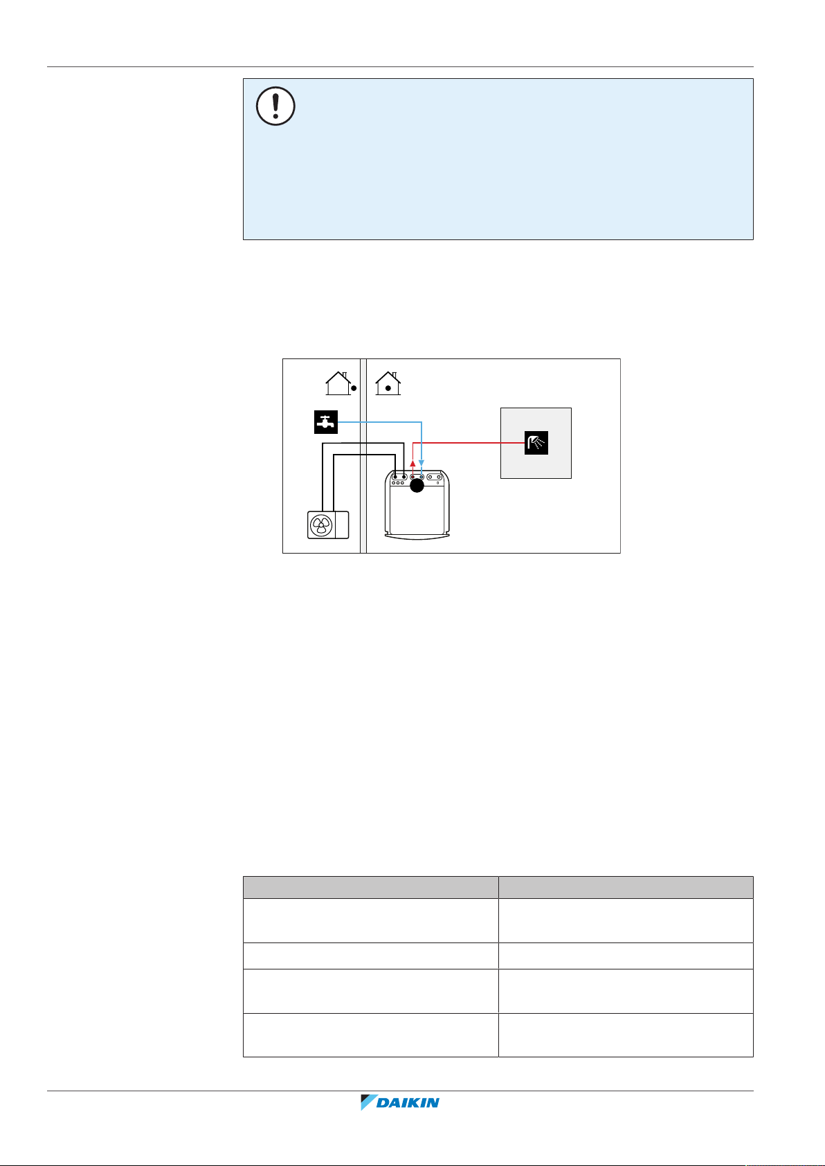
6 | Application guidelines
A
a
b
6.4 Setting up the domestic hot water tank
6.4.1 System layout – Integrated DHW tank
NOTICE
▪ Make sure the auxiliary contact has enough differential or time delay to prevent
frequent changeover between indoor unit and auxiliary boiler.
▪ If the auxiliary contact is an outdoor temperature thermostat, install the
thermostat in the shadow so that it is NOT influenced or turned ON/OFF by direct
sunlight.
▪ Frequent changeover may cause corrosion of the auxiliary boiler. Contact the
manufacturer of the auxiliary boiler for more information.
A Domestic hot water
a Cold water IN
b Hot water OUT
6.4.2 Selecting the volume and desired temperature for the DHW tank
People experience water as hot when its temperature is 40°C. Therefore, the DHW
consumption is always expressed as equivalent hot water volume at 40°C.
However, you can set the DHW tank temperature at a higher temperature
(example: 53°C), which is then mixed with cold water (example: 15°C).
Selecting the volume and desired temperature for the DHW tank consists of:
1 Determining the DHW consumption (equivalent hot water volume at 40°C).
2 Determining the volume and desired temperature for the DHW tank.
Determining the DHW consumption
Answer the following questions and calculate the DHW consumption (equivalent
hot water volume at 40°C) using typical water volumes:
Question Typical water volume
How many showers are needed per
day?
How many baths are needed per day? 1bath = 150l
1shower = 10min×10l/min = 100l
Installer reference guide
44
How much water is needed at the
1sink = 2min×5l/min = 10l
kitchen sink per day?
Are there any other domestic hot water
needs?
—
ERGA04~08EAV3(A) + EHVH04+08SU18+23EA6V
Daikin Altherma 3 R F
4P629090-1 – 2020.08
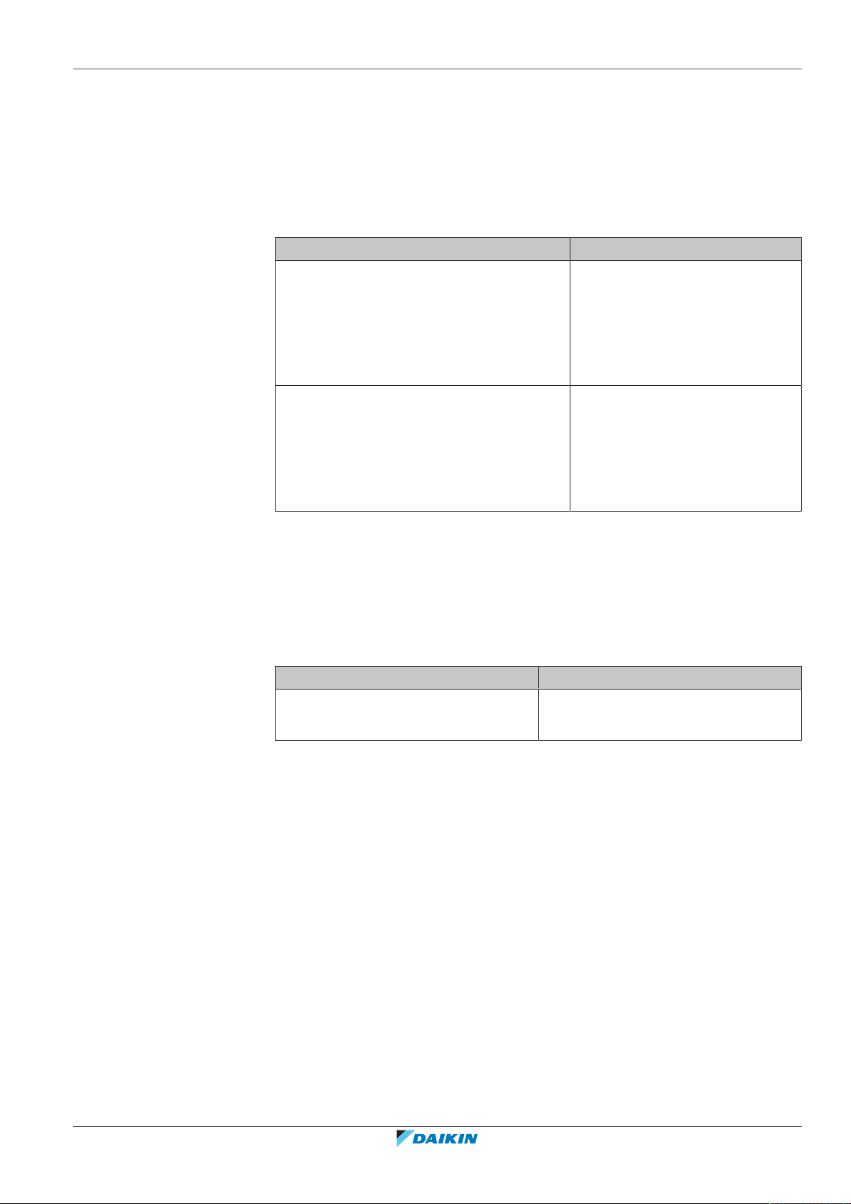
6 | Application guidelines
Example: If the DHW consumption of a family (4 persons) per day is as follows:
▪ 3 showers
▪ 1 bath
▪ 3 sink volumes
Then the DHW consumption = (3×100l)+(1×150l)+(3×10l)=480l
Determining the volume and desired temperature for the DHW tank
Formula Example
V1=V2+V2×(T2−40)/(40−T1) If:
▪ V2=180l
▪ T2=54°C
▪ T1=15°C
Then V1=280l
V2=V1×(40−T1)/(T2−T1) If:
▪ V1=480l
▪ T2=54°C
▪ T1=15°C
Then V2=307l
V1DHW consumption (equivalent hot water volume at 40°C)
V2Required DHW tank volume if only heated once
T2DHW tank temperature
T1Cold water temperature
Possible DHW tank volumes
Type Possible volumes
Integrated DHW tank ▪ 180l
▪ 230l
Energy saving tips
▪ If the DHW consumption differs from day to day, you can program a weekly
schedule with different desired DHW tank temperatures for each day.
▪ The lower the desired DHW tank temperature, the more cost effective. By
selecting a larger DHW tank, you can lower the desired DHW tank temperature.
▪ The heatpump itself can produce domestic hot water of maximum 55°C (50°C if
outdoor temperature is low). The electrical resistance integrated in the
heatpump can increase this temperature. However, this consumes more energy.
We recommend to set the desired DHW tank temperature below 55°C to avoid
using the electrical resistance.
ERGA04~08EAV3(A) + EHVH04+08SU18+23EA6V
Daikin Altherma 3 R F
4P629090-1 – 2020.08
▪ The higher the outdoor temperature, the better the performance of the
heatpump.
- If energy prices are the same during the day and the night, we recommend to
heat up the DHW tank during the day.
- If energy prices are lower during the night, we recommend to heat up the DHW
tank during the night.
Installer reference guide
45

6 | Application guidelines
a
b
c
d
6.4.3 Setup and configuration – DHW tank
6.4.4 DHW pump for instant hot water
▪ When the heatpump produces domestic hot water, it cannot heat up a space. In
case you need domestic hot water and space heating at the same, we
recommend to produce the domestic hot water during the night when there is
lower space heating demand.
▪ For large DHW consumptions, you can heat up the DHW tank several times
during the day.
▪ To heat up the DHW tank to the desired DHW tank temperature, you can use the
following energy sources:
- Thermodynamic cycle of the heatpump
- Electrical backup heater
▪ For more information about optimizing the energy consumption for producing
domestic hot water, see "10Configuration"[4131].
Setup
a Cold water IN
b Hot water OUT (shower (field supply))
c DHW pump (field supply)
d Recirculation connection
▪ By connecting a DHW pump, instant hot water can be available at the tap.
▪ The DHW pump and the installation are field supply and the responsibility of the
installer. For the electrical wiring, see "9.3.5To connect the domestic hot water
pump"[4119].
For more information about connecting the recirculation connection, see "8.6.5To
connect the recirculation piping"[4101].
Configuration
▪ For more information, see "10Configuration"[4131].
▪ You can program a schedule to control the DHW pump via the user interface. For
more information, see the user reference guide.
Installer reference guide
46
ERGA04~08EAV3(A) + EHVH04+08SU18+23EA6V
Daikin Altherma 3 R F
4P629090-1 – 2020.08

6.4.5 DHW pump for disinfection
c
a
b
d f
e g
h
i
Setup
a Cold water IN
b Hot water OUT (shower (field supply))
c DHW pump (field supply)
d Heater element (field supply)
e Non‑return valve (field supply)
▪ The DHW pump is field-supplied and its installation is the responsibility of the
installer. For the electrical wiring, see "9.3.5To connect the domestic hot water
pump"[4119].
▪ If the applicable legislation requires a higher temperature than the maximum
tank setpoint during disinfection (see [2-03] in the field settings table), you can
connect a DHW pump and heater element as shown above.
▪ If applicable legislation requires disinfection of the water piping until the tapping
point, you can connect a DHW pump and heater element (if needed) as shown
above.
6 | Application guidelines
Configuration
The indoor unit can control DHW pump operation. For more information, see
"10Configuration"[4131].
6.5 Setting up the energy metering
▪ Via the user interface, you can read out the following energy data:
- Produced heat
- Consumed energy
▪ You can read out the energy data:
- For space heating
- For space cooling
- For domestic hot water production
▪ You can read out the energy data:
- Per month
- Per year
INFORMATION
The calculated produced heat and consumed energy are an estimation, the accuracy
cannot be guaranteed.
6.5.1 Produced heat
INFORMATION
The sensors used to calculate the produced heat are calibrated automatically.
ERGA04~08EAV3(A) + EHVH04+08SU18+23EA6V
Daikin Altherma 3 R F
4P629090-1 – 2020.08
Installer reference guide
47

6 | Application guidelines
6.5.2 Consumed energy
▪ The produced heat is calculated internally based on:
- The leaving and entering water temperature
- The flow rate
▪ Setup and configuration: No additional equipment needed.
You can use the following methods to determine the consumed energy:
▪ Calculating
▪ Measuring
INFORMATION
You cannot combine calculating the consumed energy (example: for backup heater)
and measuring the consumed energy (example: for outdoor unit). If you do so, the
energy data will be invalid.
Calculating the consumed energy
▪ The consumed energy is calculated internally based on:
- The actual power input of the outdoor unit
- The set capacity of the backup heater
- The voltage
▪ Setup and configuration: To get accurate energy data, measure the capacity
(resistance measurement) and set the capacity via the user interface for the
backup heater (step1).
Measuring the consumed energy
▪ Preferred method because of higher accuracy.
▪ Requires external power meters.
▪ Setup and configuration: When using electrical power meters, set the number of
pulses/kWh for each power meter via the user interface.
INFORMATION
When measuring the electrical power consumption, make sure ALL power input of
the system is covered by the electrical power meters.
6.5.3 Normal kWh rate power supply
General rule
Installer reference guide
48
One power meter that covers the entire system is sufficient.
Setup
Connect the power meter to X5M/5 and X5M/6. See "9.3.4 To connect the
electricity meters"[4119].
ERGA04~08EAV3(A) + EHVH04+08SU18+23EA6V
Daikin Altherma 3 R F
4P629090-1 – 2020.08

Power meter type
b
5
8
0
1
5
0
0
0
c c
fed
g
A B C
a
b
5
8
0
1
5
0
0
0
gfe
h
A B C
c c d
a
In case of… Use a… power meter
6 | Application guidelines
▪ Single-phase outdoor unit
▪ Backup heater supplied from a single-
phase grid (i.e. the backup heater
model is *3V or *6V connected to a
single-phase grid)
▪ Three-phase outdoor unit
▪ Backup heater supplied from a three-
phase grid (i.e. the backup heater
model is *9W or *6V connected to a
three-phase grid)
Example
Single-phase power meter Three-phase power meter
Single-phase
(*3V, *6V (6V): 1N~230V)
Three-phase
(*6V (6T1): 3~230V)
(*9W: 3N~400V)
A Outdoor unit
B Indoor unit
C DHW tank
a Electrical cabinet (L1/N)
b Power meter (L1/N)
c Fuse (L1/N)
d Outdoor unit (L1/N)
e Indoor unit (L1/N)
f Backup heater (L1/N)
g Booster heater (L1/N)
A Outdoor unit
B Indoor unit
C DHW tank
a Electrical cabinet (L1/L2/L3/N)
b Power meter (L1/L2/L3/N)
c Fuse (L1/L2/L3/N)
d Fuse (L1/N)
e Outdoor unit (L1/L2/L3/N)
f Indoor unit (L1/L2/L3/N)
g Backup heater (L1/L2/L3/N)
h Booster heater (L1/N)
Exception
▪ You can use a second power meter if:
- The power range of one meter is insufficient.
- The electrical meter cannot easily be installed in the electrical cabinet.
- 230V and 400V three-phase grids are combined (very uncommon), because of
technical limitations of power meters.
ERGA04~08EAV3(A) + EHVH04+08SU18+23EA6V
Daikin Altherma 3 R F
4P629090-1 – 2020.08
Installer reference guide
49

6 | Application guidelines
e fe
ihg
A B
b
a
d
c
5
8
0
1
5
0
0
0
5
8
0
1
5
0
0
0
6.5.4 Preferential kWh rate power supply
▪ Connection and setup:
- Connect the second power meter to X5M/3 and X5M/4. See "9.3.4To connect
the electricity meters"[4119].
- In the software the power consumption data of both meters is added so you do
NOT have to set which meter covers which power consumption. You only need
to set the number of pulses of each power meter.
▪ See "6.5.4 Preferential kWh rate power supply" [450] for an example with two
power meters.
General rule
▪ Power meter1: Measures the outdoor unit.
▪ Power meter2: Measures the rest (i.e. indoor unit and backup heater).
Setup
▪ Connect power meter1 to X5M/5 and X5M/6.
▪ Connect power meter2 to X5M/3 and X5M/4.
See "9.3.4To connect the electricity meters"[4119].
Power meter types
▪ Power meter 1: Single- or three-phase power meter according to the power
supply of the outdoor unit.
▪ Power meter2:
- In case of a single-phase backup heater configuration, use a single-phase
power meter.
- In other cases, use a three-phase power meter.
Example
Single-phase outdoor unit with a three-phase backup heater:
Installer reference guide
50
A Outdoor unit
B Indoor unit
C DHW tank
a Electrical cabinet (L1/N): Preferential kWh rate power supply
b Electrical cabinet (L1/L2/L3/N): Normal kWh rate power supply
c Power meter (L1/N)
d Power meter (L1/L2/L3/N)
e Fuse (L1/N)
f Fuse (L1/L2/L3/N)
g Outdoor unit (L1/N)
h Indoor unit (L1/N)
i Backup heater (L1/L2/L3/N)
ERGA04~08EAV3(A) + EHVH04+08SU18+23EA6V
Daikin Altherma 3 R F
4P629090-1 – 2020.08

6.6 Setting up the power consumption control
P
i
t
DI
a
b
▪ The power consumption control:
- Allows you to limit the power consumption of the entire system (sum of
outdoor unit, indoor unit and backup heater).
- Configuration: Set the power limitation level and how it has to be achieved via
the user interface.
▪ The power limitation level can be expressed as:
- Maximum running current (inA)
- Maximum power input (inkW)
▪ The power limitation level can be activated:
- Permanently
- By digital inputs
NOTICE
Set a minimum power consumption of ±3.6kW to guarantee:
▪ Defrost operation. Otherwise, if defrosting is interrupted several times, the heat
exchanger will freeze up.
▪ Space heating and DHW production by allowing the backup heater step1.
6 | Application guidelines
6.6.1 Permanent power limitation
Permanent power limitation is useful to assure a maximum power or current input
of the system. In some countries, legislation limits the maximum power
consumption for space heating and DHW production.
PiPower input
t Time
DI Digital input (power limitation level)
a Power limitation active
b Actual power input
Setup and configuration
▪ No additional equipment needed.
▪ Set the power consumption control settings in [9.9] via the user interface (see
"Power consumption control"[4200]):
- Select continuous limitation mode
- Select the type of limitation (power in kW or current in A)
- Set the desired power limitation level
6.6.2 Power limitation activated by digital inputs
ERGA04~08EAV3(A) + EHVH04+08SU18+23EA6V
Daikin Altherma 3 R F
4P629090-1 – 2020.08
Power limitation is also useful in combination with an energy management system.
Installer reference guide
51

6 | Application guidelines
a
b
A B
C
1
2
3
4
5
A8P
P
i
t
DI4
DI3
DI1
a
b
The power or current of the entire Daikin system is limited dynamically by digital
inputs (maximum four steps). Each power limitation level is set via the user
interface by limiting one of the following:
▪ Current (in A)
▪ Power input (in kW)
The energy management system (field supply) decides the activation of a certain
power limitation level. Example: To limit the maximum power of the entire house
(lighting, domestic appliances, space heating…).
A Outdoor unit
B Indoor unit
C Energy management system
a Power limitation activation (4 digital inputs
b Backup heater
PiPower input
t Time
DI Digital inputs (power limitation levels)
a Power limitation active
b Actual power input
Setup
▪ Demand PCB (option EKRP1AHTA) needed.
▪ Maximum four digital inputs are used to activate the corresponding power
limitation level:
- DI1 = strongest limitation (lowest energy consumption)
- DI4 = weakest limitation (highest energy consumption)
▪ Specification of the digital inputs:
- DI1: S9S (limit 1)
- DI2: S8S (limit 2)
- DI3: S7S (limit 3)
- DI4: S6S (limit 4)
▪ Refer to the wiring diagram for more information.
Installer reference guide
52
ERGA04~08EAV3(A) + EHVH04+08SU18+23EA6V
Daikin Altherma 3 R F
4P629090-1 – 2020.08

Configuration
P
h
C
e
a
b
c
A B
▪ Set the power consumption control settings in [9.9] via the user interface (for the
description of all settings, see "Power consumption control"[4200]):
- Select limitation by digital inputs.
- Select the type of limitation (power in kW or current in A).
- Set the desired power limitation level corresponding to each digital input.
6.6.3 Power limitation process
The outdoor unit has better efficiency than the electrical heater. Therefore, the
electrical heater is limited and turned OFF first. The system limits power
consumption in the following order:
1 Turns OFF the backup heater.
2 Limits the outdoor unit.
3 Turns OFF the outdoor unit.
6 | Application guidelines
INFORMATION
In case more than 1 digital input is closed (at the same time), the digital input priority
is fixed: DI4 priority>…>DI1.
Example
If the configuration is as follows: Power limitation level does NOT allow operation
of backup heater (step1).
Then power consumption is limited as follows:
PhProduced heat
CeConsumed energy
A Outdoor unit
B Backup heater
a Limited outdoor unit operation
b Full outdoor unit operation
c Backup heater step1 turned ON
6.7 Setting up an external temperature sensor
ERGA04~08EAV3(A) + EHVH04+08SU18+23EA6V
Daikin Altherma 3 R F
4P629090-1 – 2020.08
You can connect one external temperature sensor. It measures the indoor or
outdoor ambient temperature. We recommend to use an external temperature
sensor in the following cases:
Installer reference guide
53

6 | Application guidelines
Indoor ambient temperature
▪ In room thermostat control, the dedicated Human Comfort Interface (BRC1HHDA
used as room thermostat) measures the indoor ambient temperature. Therefore,
the Human Comfort Interface must be installed on a location:
- Where the average temperature in the room can be detected
- That is NOT exposed to direct sunlight
- That is NOT near a heat source
- That is NOT affected by outside air or air draught because of, for example, door
opening/closing
▪ If this is NOT possible, we recommend to connect a remote indoor sensor (option
KRCS01-1).
▪ Setup: For installation instructions, see the installation manual of the remote
indoor sensor, and the addendum book for optional equipment.
▪ Configuration: Select room sensor [9.B].
Outdoor ambient temperature
▪ In the outdoor unit, the outdoor ambient temperature is measured. Therefore,
the outdoor unit must be installed on a location:
- At the north side of the house or at the side of the house where the most heat
emitters are located
- That is NOT exposed to direct sunlight
▪ If this is NOT possible, we recommend to connect a remote outdoor sensor
(option EKRSCA1).
▪ Setup: For installation instructions, see the installation manual of the remote
outdoor sensor, and the addendum book for optional equipment.
▪ Configuration: Select outdoor sensor [9.B].
▪ When the power saving functionality of the outdoor unit is active, the outdoor
unit is turned down to reduce standby energy losses. As a result, the outdoor
ambient temperature is NOT read out.
▪ If the desired leaving water temperature is weather dependent, the full time
outdoor temperature measurement is important. This is another reason to install
the optional outdoor ambient temperature sensor.
INFORMATION
The external outdoor ambient sensor data (either averaged or instantaneous) is used
in the weather-dependent control curves and in the automatic heating/cooling
changeover logic. To protect the outdoor unit, the internal sensor of the outdoor unit
is always used.
Installer reference guide
54
ERGA04~08EAV3(A) + EHVH04+08SU18+23EA6V
Daikin Altherma 3 R F
4P629090-1 – 2020.08
7 Unit installation
In this chapter
7.1 Preparing the installation site ................................................................................................................................................ 55
7.1.1 Installation site requirements of the outdoor unit ............................................................................................... 55
7.1.2 Additional installation site requirements of the outdoor unit in cold climates ................................................... 58
7.1.3 Installation site requirements of the indoor unit .................................................................................................. 59
7.2 Opening and closing the units................................................................................................................................................ 62
7.2.1 About opening the units ........................................................................................................................................ 62
7.2.2 To open the outdoor unit ...................................................................................................................................... 62
7.2.3 To close the outdoor unit....................................................................................................................................... 62
7.2.4 To open the indoor unit ......................................................................................................................................... 62
7.2.5 To lower the switch box on the indoor unit .......................................................................................................... 64
7.2.6 To close the indoor unit ......................................................................................................................................... 65
7.3 Mounting the outdoor unit .................................................................................................................................................... 65
7.3.1 About mounting the outdoor unit ......................................................................................................................... 65
7.3.2 Precautions when mounting the outdoor unit...................................................................................................... 66
7.3.3 To provide the installation structure ..................................................................................................................... 66
7.3.4 To install the outdoor unit ..................................................................................................................................... 69
7.3.5 To provide drainage ............................................................................................................................................... 70
7.3.6 To prevent the outdoor unit from falling over ...................................................................................................... 71
7.4 Mounting the indoor unit....................................................................................................................................................... 72
7.4.1 About mounting the indoor unit............................................................................................................................ 72
7.4.2 Precautions when mounting the indoor unit ........................................................................................................ 72
7.4.3 To install the indoor unit ........................................................................................................................................ 72
7.4.4 To connect the drain hose to the drain ................................................................................................................. 73
7 | Unit installation
7.1 Preparing the installation site
Do NOT install the unit in places often used as work place. In case of construction
works (e.g. grinding works) where a lot of dust is created, the unit MUST be
covered.
Choose an installation location with sufficient space for carrying the unit in and out
of the site.
WARNING
The appliance shall be stored in a room without continuously operating ignition
sources (example: open flames, an operating gas appliance or an operating electric
heater).
WARNING
DO NOT reuse refrigerant piping that has been used with any other refrigerant.
Replace the refrigerant pipes or clean thoroughly.
7.1.1 Installation site requirements of the outdoor unit
INFORMATION
Also read the following requirements:
▪ General installation site requirements. See the "General safety precautions"
chapter.
▪ Refrigerant piping requirements (length, height difference). See further in this
"Preparation" chapter.
ERGA04~08EAV3(A) + EHVH04+08SU18+23EA6V
Daikin Altherma 3 R F
4P629090-1 – 2020.08
Mind the following spacing guidelines:
Installer reference guide
55

7 | Unit installation
≤1200
>250
>250
>250
>350
>350
(mm)(mm)
a
b
b
a
>100
>350
(mm)
>100
a
a
b
b
c
a
a Air outlet
b Air inlet
INFORMATION
In sound sensitive areas (e.g. near a bedroom), you can install the low sound cover
(EKLN08A1) to decrease the operation noise of the outdoor unit. If you install it,
mind the following spacing guidelines:
a Low sound cover
NOTICE
▪ Do NOT stack the units on each other.
▪ Do NOT hang the unit on a ceiling.
Strong winds (≥18km/h) blowing against the outdoor unit’s air outlet causes short
circuit (suction of discharge air). This may result in:
▪ deterioration of the operational capacity;
▪ frequent frost acceleration in heating operation;
▪ disruption of operation due to decrease of low pressure or increase of high
pressure;
▪ a broken fan (if a strong wind blows continuously on the fan, it may start rotating
very fast, until it breaks).
It is recommended to install a baffle plate when the air outlet is exposed to wind.
It is recommended to install the outdoor unit with the air inlet facing the wall and
NOT directly exposed to the wind.
Installer reference guide
56
a Baffle plate
b Prevailing wind direction
c Air outlet
ERGA04~08EAV3(A) + EHVH04+08SU18+23EA6V
Daikin Altherma 3 R F
4P629090-1 – 2020.08

7 | Unit installation
b
c
a
a
b
c
d
c
d
Do NOT install the unit in the following places:
▪ Sound sensitive areas (e.g. near a bedroom), so that the operation noise will
cause no trouble.
Note: If the sound is measured under actual installation conditions, the
measured value might be higher than the sound pressure level mentioned in
Sound spectrum in the data book due to environmental noise and sound
reflections.
▪ In places where a mineral oil mist, spray or vapour may be present in the
atmosphere. Plastic parts may deteriorate and fall off or cause water leakage.
It is NOT recommended to install the unit in the following places because it may
shorten the life of the unit:
▪ Where the voltage fluctuates a lot
▪ In vehicles or vessels
▪ Where acidic or alkaline vapour is present
Seaside installation. Make sure the outdoor unit is NOT directly exposed to sea
winds. This is to prevent corrosion caused by high levels of salt in the air, which
might shorten the life of the unit.
Install the outdoor unit away from direct sea winds.
Example: Behind the building.
If the outdoor unit is exposed to direct sea winds, install a windbreaker.
▪ Height of windbreaker≥1.5×height of outdoor unit
▪ Mind the service space requirements when installing the windbreaker.
a Sea wind
b Building
c Outdoor unit
d Windbreaker
The outdoor unit is designed for outdoor installation only, and for the following
ambient temperatures:
Cooling mode 10~43°C
Heating mode –25~25°C
ERGA04~08EAV3(A) + EHVH04+08SU18+23EA6V
Daikin Altherma 3 R F
4P629090-1 – 2020.08
Installer reference guide
57

7 | Unit installation
2
4×
1
3
a
c
c
d
b
e
a
7.1.2 Additional installation site requirements of the outdoor unit in cold climates
In areas with low ambient temperatures and high humidity, or in areas with heavy
snowfall, remove the suction grille to ensure proper operation.
Non-exhaustive list of areas: Austria, Czech Republic, Denmark, Estonia, Finland,
Germany, Hungary, Latvia, Lithuania, Norway, Poland, Romania, Serbia, Slovakia,
Sweden, …
1 Remove the screws holding the suction grille.
2 Remove the suction grille, and dispose of it.
3 Reattach the screws to the unit.
a Suction grille
Protect the outdoor unit against direct snowfall and take care that the outdoor unit
is NEVER snowed up.
a Snow cover or shed
b Pedestal
c Prevailing wind direction
d Air outlet
e EKFT008D option kit
In any case, provide at least 300 mm of free space below the unit. Additionally,
make sure the unit is positioned at least 100mm above the maximum expected
level of snow. See "7.3Mounting the outdoor unit"[465] for more details.
In heavy snowfall areas it is very important to select an installation site where the
snow will NOT affect the unit. If lateral snowfall is possible, make sure that the heat
exchanger coil is NOT affected by the snow. If necessary, install a snow cover or
shed and a pedestal.
Installer reference guide
58
ERGA04~08EAV3(A) + EHVH04+08SU18+23EA6V
Daikin Altherma 3 R F
4P629090-1 – 2020.08

7.1.3 Installation site requirements of the indoor unit
≥300
≥650
≥
500
(mm)
≥
100
INFORMATION
Also read the precautions and requirements in the "2 General safety
precautions"[49].
▪ The indoor unit is designed for indoor installation only and for the following
ambient temperatures:
- Space heating operation: 5~30°C
- Space cooling operation: 5~35°C
- Domestic hot water production: 5~35°C
▪ Mind the following measurements guidelines:
7 | Unit installation
Maximum refrigerant piping length between indoor unit and
outdoor unit
Minimum refrigerant piping length between indoor unit and
outdoor unit
Maximum height difference between indoor unit and outdoor
unit
▪ Mind the following spacing installation guidelines:
INFORMATION
If you have limited installation space, do the following before installing the unit in its
final position: "7.4.4To connect the drain hose to the drain" [473]. It requires to
remove one or both side panels.
30m
3m
20m
▪ The foundation must be strong enough to bear the weight of the unit. Take the
weight of the unit with a domestic hot water tank full of water into account.
Make sure, in the event of a water leak, water cannot cause any damage to the
installation space and surroundings.
Do NOT install the unit in places such as:
▪ In places where a mineral oil mist, spray or vapour may be present in the
atmosphere. Plastic parts may deteriorate and fall off or cause water leakage.
▪ Sound sensitive areas (e.g. near a bedroom), so that the operation noise will
cause no trouble.
▪ In places with high humidity (max. RH=85%), for example a bathroom.
▪ In places where frost is possible. Ambient temperature around the indoor unit
must be >5°C.
Daikin Altherma 3 R F
4P629090-1 – 2020.08
ERGA04~08EAV3(A) + EHVH04+08SU18+23EA6V
Installer reference guide
59
7 | Unit installation
Special requirements for R32
WARNING
▪ Do NOT pierce or burn.
▪ Do NOT use means to accelerate the defrosting process or to clean the
equipment, other than those recommended by the manufacturer.
▪ Be aware that R32 refrigerant does NOT contain an odour.
WARNING
The appliance shall be stored so as to prevent mechanical damage and in a wellventilated room without continuously operating ignition sources (example: open
flames, an operating gas appliance or an operating electric heater) and have a room
size as specified below.
NOTICE
▪ Do NOT re-use joints and copper gaskets which have been used already.
▪ Joints made in installation between parts of refrigerant system shall be accessible
for maintenance purposes.
WARNING
Make sure installation, servicing, maintenance and repair comply with instructions
from Daikin and with applicable legislation (for example national gas regulation) and
are executed only by authorised persons.
NOTICE
▪ Pipework shall be protected from physical damage.
▪ Installation of pipework shall be kept to a minimum.
Installer reference guide
60
ERGA04~08EAV3(A) + EHVH04+08SU18+23EA6V
Daikin Altherma 3 R F
4P629090-1 – 2020.08

7 | Unit installation
Input from installer:
▪ Total refrigerant charge (m
c
) (kg)
▪ Area of room A (A
room A
) (m2)
Start
Use table 1 in chapter "Technical data" to
calculate the maximum refrigerant charge
(m
max
) (kg) allowed for room A.
Contact your dealer.
Use table 3 in chapter "Technical data" and
dm to calculate the minimum opening area for
natural ventilation between room A and
room B (VA
min
) (cm2).
Unit can be installed at room A if:
▪ 2 ventilation openings (permanently open) are provided between room A and B, 1 at the top and 1 at the bottom.
▪ Bottom opening: The bottom opening must meet the minimum area requirements (VA
min
). It must be as close as possible to the floor. If the ventilation opening
starts from the floor, the height must be ≥20 mm. The bottom of the opening must be situated ≤100 mm from the floor. At least 50% of the required opening
area must be situated <200 mm from the floor. The entire area of the opening must be situated <300 mm from the floor.
▪ Top opening: The area of the top opening must be larger than or equal to the bottom opening. The bottom of the top opening must be situated at least 1.5 m
above the top of the bottom opening.
▪ Ventilation openings to the outside are NOT considered suitable ventilation openings (the user can block them when it is cold).
The unit can be installed in room A, and
without further room size or ventilation
requirements.
Determine the refrigerant amount that exceeds
m
max
(dm) (kg). (dm=mc–m
max
)
m
max≥mc
?
Yes
No
No
Use table 2 in chapter "Technical data" to
calculate the total minimum floor area
(A
min total
) (m2) required for the total refrigerant
charge (m
c
).
A
min total≤Aroom A+Aroom B
?
Yes
Input from installer:
▪ Area of adjacent room B (A
room B
) (m2)
a Indoor unit
A Room where the indoor unit is installed.
B Room adjacent to room A.
A
a
B
≥1.5 m
If the total refrigerant charge in the system is ≥1.84 kg (i.e. if the piping length is ≥27m), you need to comply
with the minimum floor area requirements as described in the following flow chart. The flow chart uses the
following tables: "16.5Table 1 – Maximum refrigerant charge allowed in a room: indoor unit"[4260], "16.6Table
2 – Minimum floor area: indoor unit" [4 261] and "16.7Table 3 – Minimum venting opening area for natural
ventilation: indoor unit"[4261].
INFORMATION
Systems with a total refrigerant charge (mc) <1.84kg (i.e. if the piping length is <27
m) are NOT subjected to any requirements to the installation room.
INFORMATION
Multiple indoor units. If two or more indoor units are installed in a room, you must
consider the maximum refrigerant charge that can be released in the room when a
SINGLE leak occurs. Example: If two indoor units are installed in the room, each with
its own outdoor unit, then you have to consider the refrigerant charge of the largest
indoor-outdoor combination.
ERGA04~08EAV3(A) + EHVH04+08SU18+23EA6V
Daikin Altherma 3 R F
4P629090-1 – 2020.08
Installer reference guide
61

7 | Unit installation
a
b
d
c
e
7.2 Opening and closing the units
7.2.1 About opening the units
7.2.2 To open the outdoor unit
At certain times, you have to open the unit. Example:
▪ When connecting the refrigerant piping
▪ When connecting the electrical wiring
▪ When maintaining or servicing the unit
DANGER: RISK OF ELECTROCUTION
Do NOT leave the unit unattended when the service cover is removed.
DANGER: RISK OF ELECTROCUTION
See "8.3.8 To connect the refrigerant piping to the outdoor unit" [4 89] and
"9.2.1To connect the electrical wiring to the outdoor unit"[4108].
7.2.3 To close the outdoor unit
1 Close the switch box cover.
2 Close the service cover.
7.2.4 To open the indoor unit
Overview
DANGER: RISK OF BURNING/SCALDING
NOTICE
When closing the outdoor unit cover, make sure that the tightening torque does NOT
exceed 4.1N•m.
Installer reference guide
62
a Top panel
b User interface panel
c Switch box cover
d Front panel
e High voltage switch box cover
Open
1 Remove the top panel.
ERGA04~08EAV3(A) + EHVH04+08SU18+23EA6V
Daikin Altherma 3 R F
4P629090-1 – 2020.08

7 | Unit installation
5×
T25
2
1
1
3
4
X14Y
X1A
4×
T25
2 Remove the user interface panel. Open the hinges at the top and slide the top
panel upwards.
NOTICE
If you remove the user interface panel, also disconnect the cables from the back of
the user interface panel to prevent damage.
ERGA04~08EAV3(A) + EHVH04+08SU18+23EA6V
Daikin Altherma 3 R F
4P629090-1 – 2020.08
3 Remove the switch box cover.
4 If necessary, remove the front plate. This is, for example, necessary in the
following cases:
Installer reference guide
63

7 | Unit installation
2×
T25
4×
T25
▪ "7.2.5To lower the switch box on the indoor unit"[464]
▪ "7.4.4To connect the drain hose to the drain"[473]
▪ When you need access to the high voltage switch box
5 If you need access to the high voltage components, remove the high voltage
switch box cover.
Installer reference guide
64
7.2.5 To lower the switch box on the indoor unit
During the installation, you will need access to the inside of the indoor unit. To
have easier front access, put the switch box lower on the unit as follows:
Prerequisite: The user interface panel and front panel have been removed.
1 Remove the fixing plate at the top of the unit.
2 Tilt the switch box to the front and lift it out of its hinges.
ERGA04~08EAV3(A) + EHVH04+08SU18+23EA6V
Daikin Altherma 3 R F
4P629090-1 – 2020.08

7 | Unit installation
1
2
2×
T25
3
3
3 Place the switch box lower on the unit. Use the 2 hinges located lower on the
unit.
7.2.6 To close the indoor unit
1 Close the cover of the switch box.
2 Put the switch box back into place.
3 Reinstall the top panel.
4 Reinstall the side panels.
5 Reinstall the front panel.
6 Reconnect the cables to the user interface panel.
7 Reinstall the user interface panel.
NOTICE
When closing the indoor unit cover, make sure that the tightening torque does NOT
exceed 4.1N•m.
7.3 Mounting the outdoor unit
7.3.1 About mounting the outdoor unit
When
You have to mount the outdoor and indoor unit before you can connect the
refrigerant and water piping.
ERGA04~08EAV3(A) + EHVH04+08SU18+23EA6V
Daikin Altherma 3 R F
4P629090-1 – 2020.08
Installer reference guide
65

7 | Unit installation
a
b
c
7.3.2 Precautions when mounting the outdoor unit
7.3.3 To provide the installation structure
Typical workflow
Mounting the outdoor unit typically consists of the following stages:
1 Providing the installation structure.
2 Installing the outdoor unit.
3 Providing drainage.
4 Preventing the unit from falling over.
5 Protecting the unit against snow and wind by installing a snow cover and baffle
plates. See "7.1Preparing the installation site"[455].
INFORMATION
Also read the precautions and requirements in the following chapters:
▪ "2General safety precautions"[49]
▪ "7.1Preparing the installation site"[455]
Check the strength and level of the installation ground so that the unit will not
cause any operating vibration or noise.
Fix the unit securely by means of foundation bolts in accordance with the
foundation drawing.
This topic shows different installation structures. For all, use 4 sets of M8 or M10
anchor bolts, nuts and washers. In any case, provide at least 300mm of free space
below the unit. Additionally, make sure the unit is positioned at least 100 mm
above the maximum expected level of snow.
INFORMATION
The maximum height of the upper protruding part of the bolts is 15mm.
INFORMATION
If you install the U-beams in combination with the low sound cover (EKLN08A1),
different installation instructions apply for the U-beams. See the installation manual
of the low sound cover.
Installer reference guide
66
a Low sound cover
b Bottom parts of the low sound cover
c U-beams
ERGA04~08EAV3(A) + EHVH04+08SU18+23EA6V
Daikin Altherma 3 R F
4P629090-1 – 2020.08

Option 1: On mounting feet "flexi-foot with strut"
(mm)
0 mm
<150
a
>300
300
600
>100
0 mm
a Maximum snowfall height
Option 2: On plastic mounting feet
7 | Unit installation
In this case, you can use the bolts, nuts, washers and spring washers delivered with
the unit as accessories.
Option 3: On a pedestal with the EKFT008D option kit
The EKFT008D option kit is recommended in areas with heavy snowfall.
ERGA04~08EAV3(A) + EHVH04+08SU18+23EA6V
Daikin Altherma 3 R F
4P629090-1 – 2020.08
Installer reference guide
67

7 | Unit installation
300
600
<150
<150
(mm)
>300
100
a
b
0 mm
>250
>300
>250
(mm)
a
b
c
4×
a Maximum snowfall height
b EKFT008D option kit
Option 4: On brackets to the wall with the EKFT008D option kit
The EKFT008D option kit is recommended in areas with heavy snowfall.
Installer reference guide
68
a Maximum snowfall height
b EKFT008D option kit
c Anti-vibration rubber (field supply)
ERGA04~08EAV3(A) + EHVH04+08SU18+23EA6V
Daikin Altherma 3 R F
4P629090-1 – 2020.08

7.3.4 To install the outdoor unit
2×
3
2
1
a a
7 | Unit installation
CAUTION
Do NOT remove the protective cardboard before the unit is installed properly.
1 Lift the outdoor unit as described in "4.2.2To handle the outdoor unit"[421].
2 Install the outdoor unit as follows:
▪ (1) Put the unit into position (using the sling to the left and the handle to the
right).
▪ (2) Remove the sling (by pulling 1 side of the sling).
▪ (3) Fix the unit.
a Air outlet
NOTICE
Properly align the unit. Make sure the backside of the unit does NOT protrude.
ERGA04~08EAV3(A) + EHVH04+08SU18+23EA6V
Daikin Altherma 3 R F
4P629090-1 – 2020.08
3 Remove the protective cardboard and instruction sheet.
Installer reference guide
69

7 | Unit installation
a
b
b
a
c
7.3.5 To provide drainage
a Protective cardboard
b Instruction sheet
▪ Make sure that condensation water can be evacuated properly.
▪ Install the unit on a base to make sure that there is proper drainage in order to
avoid ice accumulation.
▪ Prepare a water drainage channel around the foundation to drain waste water
away from the unit.
▪ Avoid drain water flowing over the footpath, so that it does NOT become slippery
in case of ambient freezing temperatures.
▪ If you install the unit on a frame, install a waterproof plate within 150mm of the
bottom side of the unit in order to prevent water from getting into the unit and
to avoid drain water dripping (see the following figure).
NOTICE
If the drain holes of the outdoor unit are blocked up, provide space of at least
300mm below the outdoor unit.
▪ Drain pan. You can use the drain pan option (EKDP008D) to gather the drain
water. For the complete installation instructions, see the installation manual of
the drain pan. In short, the drain pan must be installed level (with a tolerance of
1° at all sides) and as follows:
Installer reference guide
70
a Drain pan
ERGA04~08EAV3(A) + EHVH04+08SU18+23EA6V
Daikin Altherma 3 R F
4P629090-1 – 2020.08

7 | Unit installation
355 mm
600 mm
a
b
d
c
c
b
b U-beams
c Drain hole insulation
▪ Drain pan heater. You can use the drain pan heater option (EKDPH008CA) to
prevent freezing-up of the drain pan. For the installation instructions, see the
installation manual of the drain pan heater.
▪ Non-heated drain tube. When using the drain pan heater without drain tube or
with a non-heated drain tube, remove the drain hole insulation (Item c on the
illustration).
INFORMATION
If you install the drain pan kit (with or without drain pan heater) in combination with
the low sound cover (EKLN08A1), different installation instructions apply for the
drain pan kit. See the installation manual of the low sound cover.
a Low sound cover
b Bottom parts of the low sound cover
c Drain pan kit
d Drain pan heater
7.3.6 To prevent the outdoor unit from falling over
ERGA04~08EAV3(A) + EHVH04+08SU18+23EA6V
Daikin Altherma 3 R F
4P629090-1 – 2020.08
In case the unit is installed in places where strong wind can tilt the unit, take
following measure:
1 Prepare 2 cables as indicated in the following illustration (field supply).
2 Place the 2 cables over the outdoor unit.
Installer reference guide
71

7 | Unit installation
3 Insert a rubber sheet between the cables and the outdoor unit to prevent the
cables from scratching the paint (field supply).
4 Attach the ends of the cables.
5 Tighten the cables.
7.4 Mounting the indoor unit
7.4.1 About mounting the indoor unit
When
You have to mount the outdoor and indoor unit before you can connect the
refrigerant and water piping.
Typical workflow
Mounting the indoor unit typically consists of the following stages:
1 Installing the indoor unit.
7.4.2 Precautions when mounting the indoor unit
INFORMATION
Also read the precautions and requirements in the following chapters:
▪ "2General safety precautions"[49]
▪ "7.1Preparing the installation site"[455]
7.4.3 To install the indoor unit
Installer reference guide
72
1 Lift the indoor unit from the pallet and place it on the floor. Also see "4.3.3To
handle the indoor unit"[423].
2 Connect the drain hose to the drain. See "7.4.4 To connect the drain hose to
the drain"[473].
3 Slide the indoor unit into position.
4 Adjust the height of the leveling feet to compensate for floor irregularities.
The maximum allowed deviation is 1°.
ERGA04~08EAV3(A) + EHVH04+08SU18+23EA6V
Daikin Altherma 3 R F
4P629090-1 – 2020.08

≤1°
NOTICE
0°
1° 1°
1
3×
T25
3
2
Do NOT tilt the unit forwards:
7 | Unit installation
7.4.4 To connect the drain hose to the drain
Water coming from the pressure relief valve is collected in the drain pan. The drain
pan is connected to a drain hose inside the unit. You must connect the drain hose
to an appropriate drain according to the applicable legislation. You can route the
drain hose through the left or right side panel.
Prerequisite: The user interface panel and front panel have been removed.
1 Remove one of the side panels.
2 Cut out the rubber grommet.
3 Pull the drain hose through the hole.
4 Reattach the side panel. Ensure the water can flow through the drain tube.
It is recommended to use a tundish to collect the water.
Option 1: Through the left side panel
ERGA04~08EAV3(A) + EHVH04+08SU18+23EA6V
Daikin Altherma 3 R F
4P629090-1 – 2020.08
Installer reference guide
73

7 | Unit installation
1
3×
T25
3
2
Option 2: Through the right side panel
Installer reference guide
74
ERGA04~08EAV3(A) + EHVH04+08SU18+23EA6V
Daikin Altherma 3 R F
4P629090-1 – 2020.08

8 Piping installation
In this chapter
8.1 Preparing refrigerant piping................................................................................................................................................... 75
8.1.1 Refrigerant piping requirements ........................................................................................................................... 75
8.1.2 Refrigerant piping insulation.................................................................................................................................. 76
8.2 Preparing water piping ........................................................................................................................................................... 76
8.2.1 Water circuit requirements ................................................................................................................................... 76
8.2.2 Formula to calculate the expansion vessel pre-pressure...................................................................................... 80
8.2.3 To check the water volume and flow rate ............................................................................................................. 80
8.2.4 Changing the pre-pressure of the expansion vessel ............................................................................................. 82
8.2.5 To check the water volume: Examples .................................................................................................................. 83
8.3 Connecting the refrigerant piping.......................................................................................................................................... 84
8.3.1 About connecting the refrigerant piping ............................................................................................................... 84
8.3.2 Precautions when connecting the refrigerant piping............................................................................................ 84
8.3.3 Guidelines when connecting the refrigerant piping.............................................................................................. 85
8.3.4 Pipe bending guidelines ......................................................................................................................................... 86
8.3.5 To flare the pipe end .............................................................................................................................................. 86
8.3.6 To braze the pipe end ............................................................................................................................................ 87
8.3.7 Using the stop valve and service port.................................................................................................................... 87
8.3.8 To connect the refrigerant piping to the outdoor unit ......................................................................................... 89
8.3.9 To connect the refrigerant piping to the indoor unit ............................................................................................ 89
8.4 Checking the refrigerant piping.............................................................................................................................................. 90
8.4.1 About checking the refrigerant piping................................................................................................................... 90
8.4.2 Precautions when checking the refrigerant piping ............................................................................................... 90
8.4.3 To check for leaks ................................................................................................................................................... 91
8.4.4 To perform vacuum drying .................................................................................................................................... 91
8.4.5 To insulate the refrigerant piping .......................................................................................................................... 92
8.5 Charging refrigerant ............................................................................................................................................................... 93
8.5.1 About charging refrigerant .................................................................................................................................... 93
8.5.2 Precautions when charging refrigerant ................................................................................................................. 94
8.5.3 To determine the additional refrigerant amount.................................................................................................. 94
8.5.4 To determine the complete recharge amount...................................................................................................... 94
8.5.5 To charge additional refrigerant ............................................................................................................................ 94
8.5.6 To fix the fluorinated greenhouse gases label....................................................................................................... 95
8.6 Connecting water piping ........................................................................................................................................................ 95
8.6.1 About connecting the water piping ....................................................................................................................... 95
8.6.2 Precautions when connecting the water piping.................................................................................................... 96
8.6.3 To connect the water piping .................................................................................................................................. 96
8.6.4 To connect the water piping for domestic hot water ........................................................................................... 98
8.6.5 To connect the recirculation piping ....................................................................................................................... 101
8.6.6 To fill the water circuit ........................................................................................................................................... 101
8.6.7 To fill the domestic hot water tank........................................................................................................................ 101
8.6.8 To insulate the water piping .................................................................................................................................. 102
8 | Piping installation
8.1 Preparing refrigerant piping
8.1.1 Refrigerant piping requirements
ERGA04~08EAV3(A) + EHVH04+08SU18+23EA6V
Daikin Altherma 3 R F
4P629090-1 – 2020.08
INFORMATION
Also read the precautions and requirements in the "2 General safety
precautions"[49].
▪ Piping material: Phosphoric acid deoxidised seamless copper.
▪ Piping diameter:
Liquid piping Ø6.4mm (1/4")
Gas piping Ø15.9mm (5/8")
▪ Piping temper grade and thickness:
Installer reference guide
75

8 | Piping installation
t
Ø
ØiØ
i
t
ØpØ
p
Outer diameter (Ø) Temper grade Thickness (t)
6.4mm (1/4") Annealed (O) ≥0.8mm
15.9mm (5/8") Annealed (O) ≥1.0mm
(a)
Depending on the applicable legislation and the maximum working pressure of the unit
(see "PS High" on the unit name plate), larger piping thickness might be required.
8.1.2 Refrigerant piping insulation
▪ Use polyethylene foam as insulation material:
- with a heat transfer rate between 0.041 and 0.052 W/mK (0.035 and
0.045kcal/mh°C)
- with a heat resistance of at least 120°C
▪ Insulation thickness
Pipe outer diameter (Øp) Insulation inner diameter
6.4mm (1/4") 8~10mm 10mm
15.9mm (5/8") 16~20mm 13mm
(a)
Insulation thickness (t)
(Øi)
If the temperature is higher than 30°C and the humidity is higher than RH80%, the
thickness of the insulation materials should be at least 20 mm to prevent
condensation on the surface of the insulation.
8.2 Preparing water piping
▪ Valve towards expansion vessel. The valve towards the expansion vessel (if
equipped) MUST be open.
8.2.1 Water circuit requirements
INFORMATION
Also read the precautions and requirements in the "2 General safety
precautions"[49].
NOTICE
In case of plastic pipes, make sure they are fully oxygen diffusion tight according to
DIN4726. The diffusion of oxygen into the piping can lead to excessive corrosion.
▪ Connecting piping – Legislation. Make all piping connections in accordance with
the applicable legislation and the instructions in the "Installation" chapter,
respecting the water inlet and outlet.
▪ Connecting piping – Force. Do NOT use excessive force when connecting the
piping. Deformation of the piping can cause malfunctioning of the unit.
▪ Connecting piping – Tools. Only use appropriate tooling to handle brass, which is
a soft material. If NOT, pipes will get damaged.
Installer reference guide
76
ERGA04~08EAV3(A) + EHVH04+08SU18+23EA6V
Daikin Altherma 3 R F
4P629090-1 – 2020.08
8 | Piping installation
▪ Connecting piping – Air, moisture, dust. If air, moisture or dust gets into the
circuit, problems may occur. To prevent this:
- Only use clean pipes
- Hold the pipe end downwards when removing burrs.
- Cover the pipe end when inserting it through a wall, to prevent dust and/or
particles from entering the pipe.
- Use a decent thread sealant to seal connections.
▪ Closed circuit. Use the indoor unit ONLY in a closed water system. Using the
system in an open water system will lead to excessive corrosion.
▪ Glycol. For safety reasons, it is NOT allowed to add any kind of glycol to the
water circuit.
▪ Piping length. It is recommended to avoid long runs of piping between the
domestic hot water tank and the hot water end point (shower, bath,…) and to
avoid dead ends.
▪ Piping diameter. Select the water piping diameter in relation to the required
water flow and the available external static pressure of the pump. See
"16Technical data"[4249] for the external static pressure curves of the indoor
unit.
▪ Water flow. You can find the minimum required water flow for indoor unit
operation in the following table. In all cases, this flow needs to be guaranteed.
When the flow is lower, the indoor unit will stop operation and display error 7H.
Minimum required flow rate
12l/min
▪ Field supply components – Water. Only use materials that are compatible with
water used in the system and with the materials used in the indoor unit.
▪ Field supply components – Water pressure and temperature. Check that all
components in the field piping can withstand the water pressure and water
temperature.
▪ Water pressure. The maximum water pressure is 4 bar. Provide adequate
safeguards in the water circuit to ensure that the maximum pressure is NOT
exceeded.
▪ Water temperature. All installed piping and piping accessories (valve,
connections,…) MUST withstand the following temperatures:
INFORMATION
The following illustration is an example and might NOT match your system layout.
ERGA04~08EAV3(A) + EHVH04+08SU18+23EA6V
Daikin Altherma 3 R F
4P629090-1 – 2020.08
Installer reference guide
77
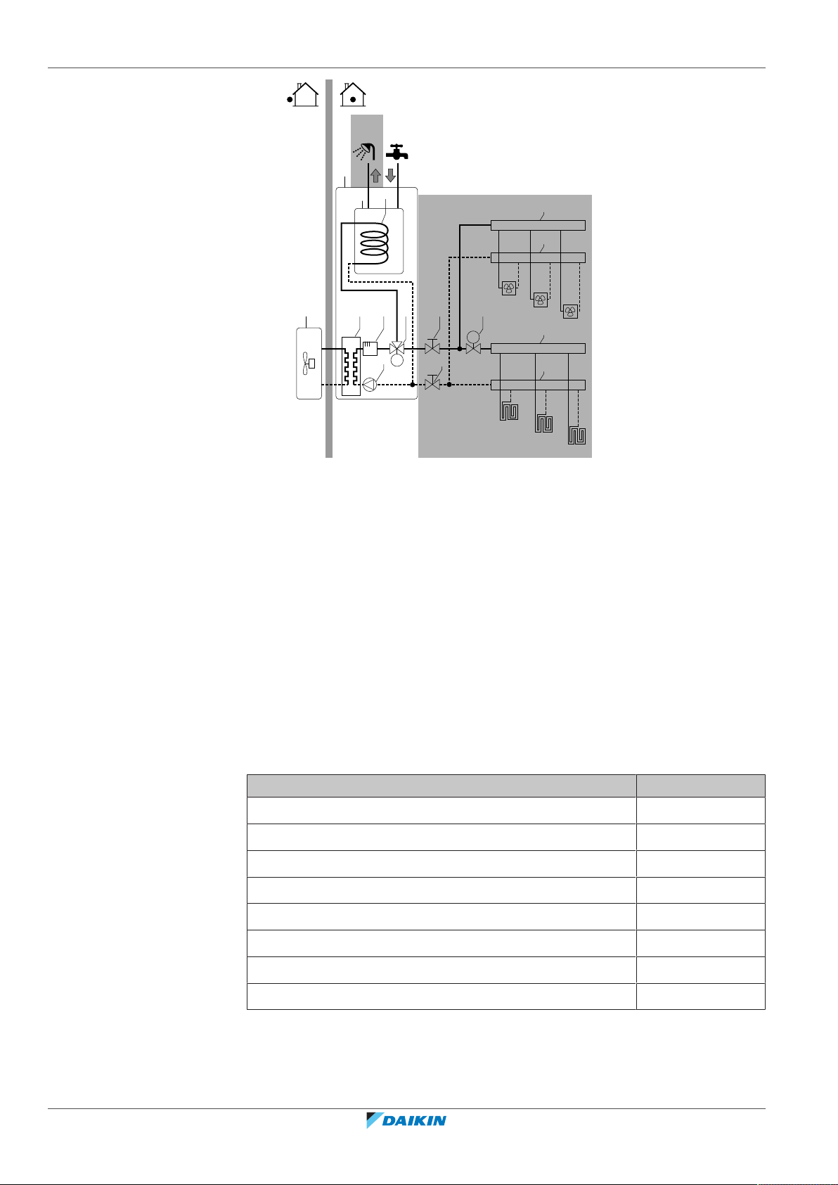
8 | Piping installation
M
M
FCU1
FCU2
FCU3
FHL1
FHL2
FHL3
a
b
c d
e f
g f h
i
i
i
i
j k
89°C
75°C
a Outdoor unit h Motorised 2-way valve (field
supply)
b Indoor unit i Collector
c Heat exchanger j Domestic hot water tank
d Backup heater k Heat exchanger coil
e Pump FCU1...3 Fan coil unit (optional) (field
supply)
f Stop valve FHL1...3 Floor heating loop (field supply)
g Motorised 3-way valve T Room thermostat (optional)
(field supply)
▪ Drainage – Low points. Provide drain taps at all low points of the system in order
to allow complete drainage of the water circuit.
▪ Drainage – Pressure relief valves. Provide a proper drain for the pressure relief
valves (of both the domestic hot water tank and the domestic hot water tank kit)
to avoid water spillage around the unit. For the discharge piping connected to
these valves, respect the requirements from the table below. For more
information, see "8.6.4 To connect the water piping for domestic hot
water"[498].
Item Requirement
Pressure relief valve diameter 15mm
Discharge pipe diameter (to pressure relief valve) 15mm
Discharge piping diameter (from tundish) 22mm
Installer reference guide
78
Discharge piping material (from tundish) Metal
Vertical length below tundish, before first elbow or bend ≥300mm
Continuous fall after first elbow or bend ≥1:200
Maximum resistance
(a)
≤9m
Resistance created by each elbow or bend 0.8m
(a)
The maximum allowed resistance (i.e. equivalent length) is expressed as a length of
straight pipe (i.e. no elbows or bends).
ERGA04~08EAV3(A) + EHVH04+08SU18+23EA6V
Daikin Altherma 3 R F
4P629090-1 – 2020.08

8 | Piping installation
a
b
e
c
d
f
e
i
g g
h h
e
f
NOTICE
All piping MUST be installed according to section G3 of the Building Regulations.
▪ Drainage – Pressure relief valve. Connect the drain hose properly to the drain to
avoid water dripping out of the unit. See "7.4.4To connect the drain hose to the
drain"[473].
▪ Air vents. Provide air vents at all high points of the system, which must also be
easily accessible for servicing. Two automatic air purges are provided in the
indoor unit. Check that the air purges are NOT tightened too much, so that
automatic release of air in the water circuit is possible.
▪ Zn-coated parts. Never use zinc coated parts in the water circuit. Because the
internal water circuit of the unit uses copper piping, excessive corrosion may
occur.
▪ Non-brass metallic piping. When using non-brass metallic piping, insulate the
brass and non-brass properly so that they do NOT make contact with each other.
This to prevent galvanic corrosion.
▪ Valve – Change‑over time. When using a 2-way valve or a 3-way valve in the
water circuit, the maximum change-over time of the valve must be 60seconds.
▪ Domestic hot water tank – Capacity. To avoid stagnation of water, it is
important that the storage capacity of the domestic hot water tank meets the
daily consumption of domestic hot water.
▪ Domestic hot water tank – After installation. Immediately after installation, the
domestic hot water tank must be flushed with fresh water. This procedure must
be repeated at least once a day the first 5 consecutive days after installation.
▪ Domestic hot water tank – Standstills. In cases where during longer periods of
time there is no consumption of hot water, the equipment MUST be flushed with
fresh water before usage.
▪ Domestic hot water tank – Disinfection. For the disinfection function of the
domestic hot water tank, see "10.5.6Tank"[4179].
▪ Domestic hot water tank kit – Clean pipes. Before installing the domestic hot
water tank kit, all piping and fittings must be flushed free of flux and debris.
Failure to do this may cause irreparable damage to the tank kit control valves.
Flush the system by opening the hot water tap.
▪ Domestic hot water tank kit – Pressure balancing. To prevent large pressure
differences at the taps and damage to the shower valve due to high‑pressure
cold water (5bar), provide a dedicated 3.5‑bar feed to both cold water and hot
water taps. To do this, also connect the cold water supply for the cold water taps
to the pressure reducing valve of the domestic hot water tank kit.
ERGA04~08EAV3(A) + EHVH04+08SU18+23EA6V
Daikin Altherma 3 R F
4P629090-1 – 2020.08
a Cold water supply into house at 5bar
b To 5bar taps
c Pressure reducing valve (set to 3.5bar) (part of the domestic hot water tank kit)
d Indoor unit
e Dedicated 3.5bar feed – to/from DHW tank
f Dedicated 3.5bar feed – cold water
Installer reference guide
79

8 | Piping installation
c
d
a b
g Cold water taps
h Hot water taps
i Shower
▪ Domestic hot water tank – Pressure relief valve. A pressure relief valve (part of
the inlet control group) with an opening pressure of 8 bar prevents excessive
water pressure in the water circuit.
▪ Domestic hot water tank – Pressure and temperature relief valve. The pressure
and temperature relief valve prevents excessive water pressure (≥10 bar) and
excessive water temperature (>95°C) in the domestic hot water tank.
▪ Thermostatic mixing valves. In accordance with the applicable legislation, it may
be necessary to install thermostatic mixing valves.
▪ Hygienic measures. The installation must be in compliance with the applicable
legislation and may require additional hygienic installation measures.
▪ Recirculation pump. In accordance with the applicable legislation, it may be
required to connect a recirculation pump in between the hot water end point
and the recirculation connection of the domestic hot water tank.
a Recirculation connection
b Hot water connection
c Shower
d Recirculation pump
▪ Valve towards expansion vessel. The valve towards the expansion vessel (if
equipped) MUST be open.
8.2.2 Formula to calculate the expansion vessel pre-pressure
The pre-pressure (Pg) of the vessel depends on the installation height difference
(H):
Pg=0.3+(H/10) (bar)
8.2.3 To check the water volume and flow rate
The indoor unit has an expansion vessel of 10litre with a factory-set pre-pressure
of 1bar.
To make sure that the unit operates properly:
▪ You must check the minimum and maximum water volume.
▪ You might need to adjust the pre-pressure of the expansion vessel.
Minimum water volume
Installer reference guide
80
There are no requirements for the minimum water volume.
INFORMATION
In critical processes, or in rooms with a high heat load, extra water might be
required.
ERGA04~08EAV3(A) + EHVH04+08SU18+23EA6V
Daikin Altherma 3 R F
4P629090-1 – 2020.08
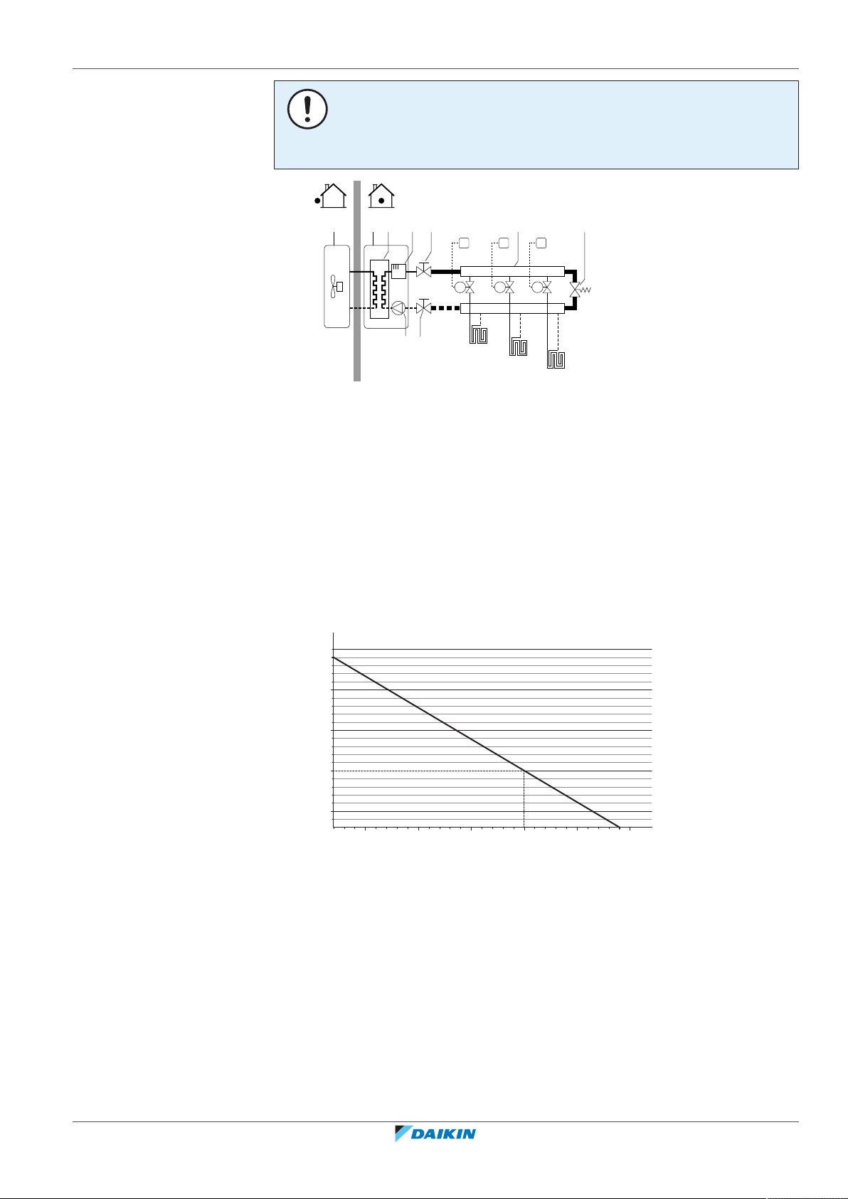
8 | Piping installation
FHL1
FHL2
FHL3
M1
T1
M2T2M3
T3
fdcba
f
g h
e
0.3
0.5
1
1.5
2
2.4
5020 100 150 200 250 290
a
b
NOTICE
When circulation in each space heating/cooling loop is controlled by remotely
controlled valves, it is important that the minimum water volume is guaranteed,
even if all of the valves are closed.
a Outdoor unit
b Indoor unit
c Heat exchanger
d Backup heater
e Pump
f Shut-off valve
g Collector (field supply)
h Overpressure bypass valve (delivered as accessory)
FHL1...3 Floor heating loop (field supply)
T1...3 Individual room thermostat (optional)
M1...3 Individual motorised valve to control loop FHL1...3 (field supply)
Maximum water volume
Use the following graph to determine the maximum water volume for the
calculated pre-pressure.
a Pre-pressure (bar)
b Maximum water volume (l)
Example: Maximum water volume and expansion vessel pre-pressure
ERGA04~08EAV3(A) + EHVH04+08SU18+23EA6V
Daikin Altherma 3 R F
4P629090-1 – 2020.08
Installer reference guide
81

8 | Piping installation
Installation
height
difference
(a)
≤200l >200l
Water volume
≤7m No pre-pressure adjustment is
required.
>7m Do the following:
▪ Increase the pre-pressure
according to the required
installation height
difference. The pre-pressure
should increase by 0.1 bar
for each metre above 7 m.
Do the following:
▪ Decrease the pre-pressure
according to the required
installation height
difference. The pre-pressure
should decrease by 0.1 bar
for each metre below 7 m.
▪ Check if the water volume
does NOT exceed the
maximum allowed water
volume.
The expansion vessel of the
indoor unit is too small for the
installation. In this case, it is
recommended to install an
extra vessel outside the unit.
▪ Check if the water volume
does NOT exceed the
maximum allowed water
volume.
(a)
This is the height difference (m) between the highest point of the water circuit and the
indoor unit. If the indoor unit is at the highest point of the installation, the installation
height is 0m.
Minimum flow rate
Check that the minimum flow rate in the installation is guaranteed in all conditions.
This minimum flow rate is required during defrost/backup heater operation. For
this purpose, use the overpressure bypass valve delivered with the unit.
Minimum required flow rate
12l/min
NOTICE
When circulation in each or certain space heating loops is controlled by remotely
controlled valves, it is important that the minimum flow rate is guaranteed, even if all
valves are closed. In case the minimum flow rate cannot be reached, a flow error 7H
will be generated (no heating or operation).
See the recommended procedure as described in "11.4 Checklist during
commissioning"[4217].
8.2.4 Changing the pre-pressure of the expansion vessel
Installer reference guide
82
NOTICE
Only a licensed installer may adjust the pre-pressure of the expansion vessel.
ERGA04~08EAV3(A) + EHVH04+08SU18+23EA6V
Daikin Altherma 3 R F
4P629090-1 – 2020.08

8 | Piping installation
a
The default pre-pressure of the expansion vessel is 1bar. When it is required to
change the pre-pressure, take following guidelines into account:
▪ Only use dry nitrogen to set the expansion vessel pre-pressure.
▪ Inappropriate setting of the expansion vessel pre-pressure will lead to
malfunction of the system.
Changing the pre-pressure of the expansion vessel should be done by releasing or
increasing nitrogen pressure through the Schrader valve of the expansion vessel.
a Schrader valve
8.2.5 To check the water volume: Examples
Example 1
The indoor unit is installed 5 m below the highest point in the water circuit. The
total water volume in the water circuit is 100l.
No actions or adjustments are required.
Example 2
The indoor unit is installed at the highest point in the water circuit. The total water
volume in the water circuit is 250l.
Actions:
▪ Because the total water volume (250 l) is more than the default water volume
(200l), the pre-pressure must be decreased.
▪ The required pre-pressure is:
Pg = (0.3+(H/10))bar = (0.3+(0/10))bar = 0.3bar
▪ The corresponding maximum water volume at 0.3bar is 290l. (See the graph in
"Maximum water volume"[481]).
▪ Because 250 l is lower than 290l, the expansion vessel is appropriate for the
installation.
ERGA04~08EAV3(A) + EHVH04+08SU18+23EA6V
Daikin Altherma 3 R F
4P629090-1 – 2020.08
Installer reference guide
83

8 | Piping installation
8.3 Connecting the refrigerant piping
8.3.1 About connecting the refrigerant piping
WARNING
▪ Only use R32 as refrigerant. Other substances may cause explosions and
accidents.
▪ R32 contains fluorinated greenhouse gases. Its global warming potential (GWP)
value is 675. Do NOT vent these gases into the atmosphere.
▪ When charging refrigerant, ALWAYS use protective gloves and safety glasses.
Before connecting the refrigerant piping
Make sure the outdoor and indoor unit are mounted.
Typical workflow
Connecting the refrigerant piping involves:
▪ Connecting the refrigerant piping to the outdoor unit
▪ Connecting the refrigerant piping to the indoor unit
▪ Insulating the refrigerant piping
▪ Keeping in mind the guidelines for:
- Pipe bending
- Flaring pipe ends
- Brazing
- Using the stop valves
8.3.2 Precautions when connecting the refrigerant piping
INFORMATION
Also read the precautions and requirements in the following chapters:
▪ "2General safety precautions"[49]
▪ "8.1Preparing refrigerant piping"[475]
DANGER: RISK OF BURNING/SCALDING
CAUTION
▪ Do NOT use mineral oil on flared part.
▪ Do NOT reuse piping from previous installations.
▪ NEVER install a drier to this R32 unit to guarantee its lifetime. The drying material
may dissolve and damage the system.
Installer reference guide
84
ERGA04~08EAV3(A) + EHVH04+08SU18+23EA6V
Daikin Altherma 3 R F
4P629090-1 – 2020.08

8 | Piping installation
a
b
c
d
NOTICE
Take the following precautions on refrigerant piping into account:
▪ Avoid anything but the designated refrigerant to get mixed into the refrigerant
cycle (e.g. air).
▪ Only use R32 when adding refrigerant.
▪ Only use installation tools (e.g. manifold gauge set) that are exclusively used for
R32 installations to withstand the pressure and to prevent foreign materials (e.g.
mineral oils and moisture) from mixing into the system.
▪ Install the piping so that the flare is NOT subjected to mechanical stress.
▪ Protect the piping as described in the following table to prevent dirt, liquid or
dust from entering the piping.
▪ Use caution when passing copper tubes through walls (see figure below).
Unit Installation period Protection method
Outdoor unit >1month Pinch the pipe
<1month Pinch or tape the pipe
Indoor unit Regardless of the period
INFORMATION
Do NOT open the refrigerant stop valve before checking the refrigerant piping. When
you need to charge additional refrigerant it is recommended to open the refrigerant
stop valve after charging.
8.3.3 Guidelines when connecting the refrigerant piping
Take the following guidelines into account when connecting pipes:
▪ Coat the flare inner surface with ether oil or ester oil when connecting a flare
nut. Tighten 3 or 4 turns by hand, before tightening firmly.
▪ ALWAYS use 2 wrenches together when loosening a flare nut.
▪ ALWAYS use a spanner and torque wrench together to tighten the flare nut when
connecting the piping. This to prevent nut cracking and leaks.
a Torque wrench
b Spanner
c Piping union
ERGA04~08EAV3(A) + EHVH04+08SU18+23EA6V
Daikin Altherma 3 R F
4P629090-1 – 2020.08
d Flare nut
Installer reference guide
85

8 | Piping installation
R=
0.4~0.8
±2
45°
90°
±2
ØA
a b
A
a b
c
Piping size (mm) Tightening torque
Ø6.4 15~17 8.7~9.1
Ø15.9 62~75 19.3~19.7
8.3.4 Pipe bending guidelines
Use a pipe bender for bending. All pipe bends should be as gentle as possible
(bending radius should be 30~40 mm or larger).
8.3.5 To flare the pipe end
1 Cut the pipe end with a pipe cutter.
(N•m)
Flare dimensions
(A) (mm)
Flare shape (mm)
CAUTION
▪ Incomplete flaring may cause refrigerant gas leakage.
▪ Do NOT re-use flares. Use new flares to prevent refrigerant gas leakage.
▪ Use flare nuts that are included with the unit. Using different flare nuts may
cause refrigerant gas leakage.
2 Remove burrs with the cut surface facing down so that the chips do NOT enter
the pipe.
a Cut exactly at right angles.
b Remove burrs.
3 Remove the flare nut from the stop valve and put the flare nut on the pipe.
4 Flare the pipe. Set exactly at the position as shown in the following figure.
Flare tool for R32
(clutch type)
(Ridgid-type)
Conventional flare tool
Clutch type
Wing nut type
(Imperial-type)
A 0~0.5mm 1.0~1.5mm 1.5~2.0mm
5 Check that the flaring is properly made.
Installer reference guide
86
a Flare’s inner surface MUST be flawless.
b The pipe end MUST be evenly flared in a perfect circle.
c Make sure the flare nut is fitted.
ERGA04~08EAV3(A) + EHVH04+08SU18+23EA6V
Daikin Altherma 3 R F
4P629090-1 – 2020.08

8.3.6 To braze the pipe end
a b c d e
f
f
c
d
a
b
The indoor unit and outdoor unit have flare connections. Connect both ends
without brazing. If brazing should be needed, take the following into account:
▪ When brazing, blow through with nitrogen to prevent creation of large quantities
of oxidised film on the inside of the piping. This film adversely affects valves and
compressors in the refrigerating system and prevents proper operation.
▪ Set the nitrogen pressure to 20kPa (0.2bar) (just enough so it can be felt on the
skin) with a pressure-reducing valve.
▪ Do NOT use anti-oxidants when brazing pipe joints.
8 | Piping installation
a Refrigerant piping
b Part to be brazed
c Taping
d Manual valve
e Pressure-reducing valve
f Nitrogen
Residue can clog pipes and break equipment.
▪ Do NOT use flux when brazing copper-to-copper refrigerant piping. Use phosphor
copper brazing filler alloy (BCuP), which does not require flux.
Flux has an extremely harmful influence on refrigerant piping systems. For
instance, if chlorine based flux is used, it will cause pipe corrosion or, in
particular, if the flux contains fluorine, it will deteriorate the refrigerant oil.
▪ Always protect the surrounding surfaces (e.g. insulation foam) from heat when
brazing.
8.3.7 Using the stop valve and service port
To handle the stop valve
Take the following guidelines into account:
▪ The stop valves are factory closed.
▪ The following figure shows the stop valve parts required when handling the
valve.
ERGA04~08EAV3(A) + EHVH04+08SU18+23EA6V
Daikin Altherma 3 R F
4P629090-1 – 2020.08
a Service port and service port cap
b Valve stem
c Field piping connection
d Stem cap
▪ Keep both stop valves open during operation.
▪ Do NOT apply excessive force to the valve stem. Doing so may break the valve
body.
▪ ALWAYS make sure to secure the stop valve with a spanner, then loosen or
tighten the flare nut with a torque wrench. Do NOT place the spanner on the
stem cap, as this could cause a refrigerant leak.
Installer reference guide
87

8 | Piping installation
a
b
To open/close the stop valve
a Spanner
b Torque wrench
▪ When it is expected that the operating pressure will be low (e.g. when cooling
will be performed while the outside air temperature is low), sufficiently seal the
flare nut in the stop valve on the gas line with silicon sealant to prevent freezing.
Silicon sealant, make sure there is no gap.
1 Remove the stop valve cover.
2 Insert a hexagon wrench (liquid side: 4 mm, gas side: 4mm) into the valve
stem and turn the valve stem:
3 When the stop valve CANNOT be turned any further, stop turning.
4 Install the stop valve cover.
Result: The valve is now open/closed.
To handle the stem cap
▪ The stem cap is sealed where indicated with the arrow. Do NOT damage it.
▪ After handling the stop valve, tighten the stem cap, and check for refrigerant
leaks.
Stem cap, liquid side 13.5~16.5
Stem cap, gas side 22.5~27.5
To handle the service cap
▪ ALWAYS use a charge hose equipped with a valve depressor pin, since the service
port is a Schrader type valve.
Counterclockwise to open
Clockwise to close
Item Tightening torque (N∙m)
Installer reference guide
88
▪ After handling the service port, tighten the service port cap, and check for
refrigerant leaks.
Item Tightening torque (N∙m)
Service port cap 11.5~13.9
ERGA04~08EAV3(A) + EHVH04+08SU18+23EA6V
Daikin Altherma 3 R F
4P629090-1 – 2020.08

8.3.8 To connect the refrigerant piping to the outdoor unit
1×
1
2
a
b
c
b
a
1 Connect the liquid refrigerant connection from the indoor unit to the liquid
stop valve of the outdoor unit.
8 | Piping installation
a Liquid stop valve
b Gas stop valve
c Service port
2 Connect the gas refrigerant connection from the indoor unit to the gas stop
valve of the outdoor unit.
NOTICE
It is recommended that the refrigerant piping between indoor and outdoor unit is
installed in a ducting or the refrigerant piping is wrapped with finishing tape.
8.3.9 To connect the refrigerant piping to the indoor unit
1 Connect the liquid stop valve from the outdoor unit to the refrigerant liquid
connection of the indoor unit.
a Refrigerant liquid connection
b Refrigerant gas connection
2 Connect the gas stop valve from the outdoor unit to the refrigerant gas
connection of the indoor unit.
NOTICE
ERGA04~08EAV3(A) + EHVH04+08SU18+23EA6V
Daikin Altherma 3 R F
4P629090-1 – 2020.08
It is recommended that the refrigerant piping between indoor and outdoor unit is
installed in a ducting or the refrigerant piping is wrapped with finishing tape.
Installer reference guide
89

8 | Piping installation
8.4 Checking the refrigerant piping
8.4.1 About checking the refrigerant piping
INFORMATION
When the indoor unit is installed in a place with limited space, an optional pipe bend
(EKHVTC) kit can be installed to facilitate the connection to the refrigerant gas and
liquid connections of the indoor unit. For installation instructions, see the instruction
sheet of the pipe bend kit.
The outdoor unit's internal refrigerant piping has been factory tested for leaks. You
only have to check the outdoor unit's external refrigerant piping.
Before checking the refrigerant piping
Make sure the refrigerant piping is connected between the outdoor unit and the
indoor unit.
Typical workflow
Checking the refrigerant piping typically consists of the following stages:
1 Checking for leaks in the refrigerant piping.
2 Performing vacuum drying to remove all moisture, air or nitrogen from the
refrigerant piping.
If there is a possibility of moisture being present in the refrigerant piping (for
example, water may have entered the piping), first carry out the vacuum drying
procedure below until all moisture has been removed.
8.4.2 Precautions when checking the refrigerant piping
INFORMATION
Also read the precautions and requirements in the following chapters:
▪ "2General safety precautions"[49]
▪ "8.1Preparing refrigerant piping"[475]
NOTICE
Use a 2-stage vacuum pump with a non-return valve that can evacuate to a gauge
pressure of −100.7kPa (−1.007bar)(5Torr absolute). Make sure the pump oil does
not flow oppositely into the system while the pump is not working.
NOTICE
Use this vacuum pump for R32 exclusively. Using the same pump for other
refrigerants may damage the pump and the unit.
Installer reference guide
90
NOTICE
▪ Connect the vacuum pump to the service port of the gas stop valve.
▪ Make sure that the gas stop valve and liquid stop valve are firmly closed before
performing the leak test or vacuum drying.
ERGA04~08EAV3(A) + EHVH04+08SU18+23EA6V
Daikin Altherma 3 R F
4P629090-1 – 2020.08

8.4.3 To check for leaks
a d
j
b
f
e
c
g h i
h
1 Charge the system with nitrogen gas up to a gauge pressure of at least
8 | Piping installation
NOTICE
Do NOT exceed the unit's maximum working pressure (see "PS High" on the unit
name plate).
NOTICE
ALWAYS use a recommended bubble test solution from your wholesaler.
NEVER use soap water:
▪ Soap water may cause cracking of components, such as flare nuts or stop valve
caps.
▪ Soap water may contain salt, which absorbs moisture that will freeze when the
piping gets cold.
▪ Soap water contains ammonia which may lead to corrosion of flared joints
(between the brass flare nut and the copper flare).
200kPa (2bar). It is recommended to pressurize to 3000kPa (30bar) in order
to detect small leaks.
2 Check for leaks by applying the bubble test solution to all connections.
3 Discharge all nitrogen gas.
8.4.4 To perform vacuum drying
Connect the vacuum pump and manifold as follows:
a Pressure meter
b Gauge manifold
c Low pressure valve (Lo)
d High-pressure valve (Hi)
e Charging hoses
g Service port
h Valve lids
1 Vacuum the system until the pressure on the manifold indicates −0.1 MPa
(−1bar).
f Vacuum pump
i Gas stop valve
j Liquid stop valve
2 Leave as is for 4-5minutes and check the pressure:
If the pressure… Then…
Does not change There is no moisture in the system.
This procedure is finished.
Increases There is moisture in the system. Go
ERGA04~08EAV3(A) + EHVH04+08SU18+23EA6V
Daikin Altherma 3 R F
4P629090-1 – 2020.08
to the next step.
Installer reference guide
91

8 | Piping installation
g
b
a
f
e
cd
3 Vacuum the system for at least 2 hours to a manifold pressure of −0.1 MPa
(−1bar).
4 After turning the pump OFF, check the pressure for at least 1hour.
5 If you do NOT reach the target vacuum or CANNOT maintain the vacuum for
1hour, do the following:
▪ Check for leaks again.
▪ Perform vacuum drying again.
NOTICE
Make sure to open the stop valves after installing the refrigerant piping and
performing vacuum drying. Running the system with the stop valves closed may
break the compressor.
INFORMATION
After opening the stop valve, it is possible that the pressure in the refrigerant piping
does NOT increase. This might be caused by e.g. the closed state of the expansion
valve in the outdoor unit circuit, but does NOT present any problem for correct
operation of the unit.
8.4.5 To insulate the refrigerant piping
After finishing the leak test and vacuum drying, the piping must be insulated. Take
into account the following points:
▪ Be sure to insulate the liquid and gas piping (for all units).
▪ Use heat resistant polyethylene foam which can withstand a temperature of 70°C
for liquid piping and polyethylene foam which can withstand a temperature of
120°C for gas piping.
▪ Reinforce the insulation on the refrigerant piping according to the installation
environment.
NOTICE
It is recommended that the refrigerant piping between indoor and outdoor unit is
installed in a ducting or the refrigerant piping is wrapped with finishing tape.
1 Insulate and fix the refrigerant piping and cables as follows:
a Gas pipe
b Gas pipe insulation
c Interconnection cable
d Field wiring (if applicable)
e Liquid pipe
f Liquid pipe insulation
g Finishing tape
2 Install the service cover.
Installer reference guide
92
ERGA04~08EAV3(A) + EHVH04+08SU18+23EA6V
Daikin Altherma 3 R F
4P629090-1 – 2020.08
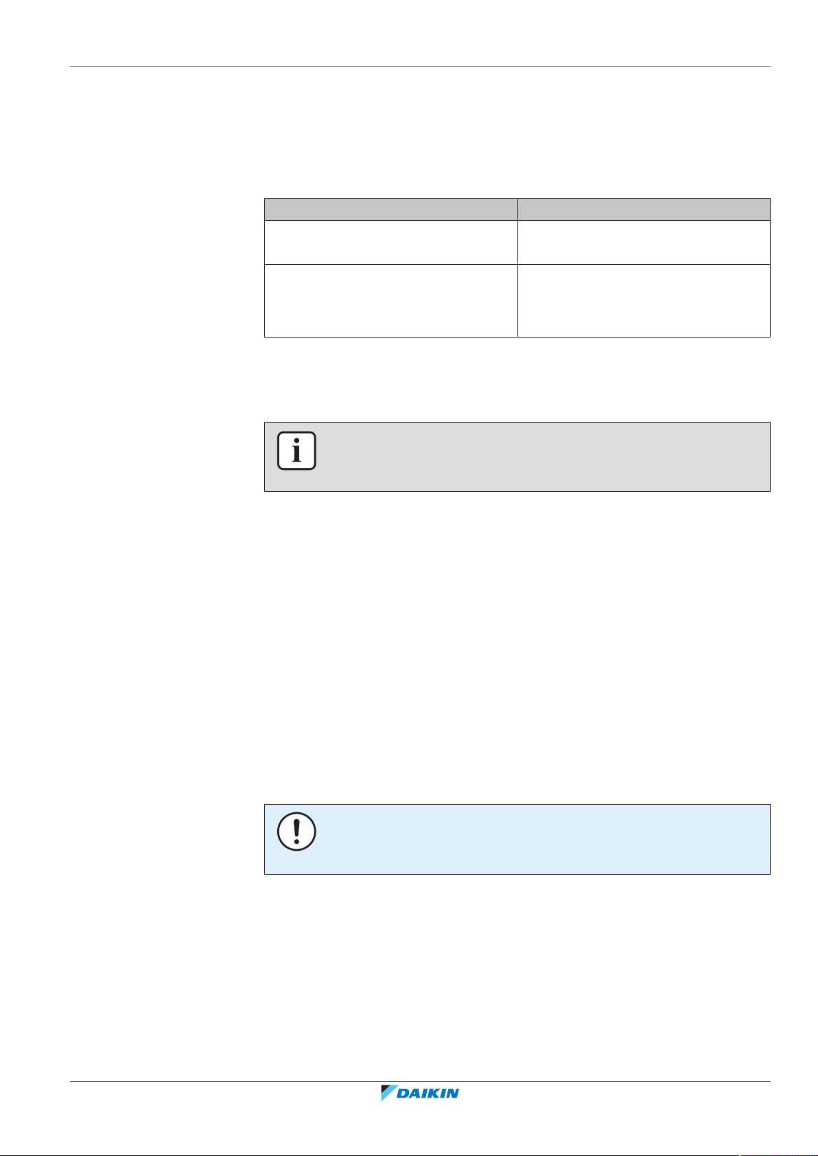
8.5 Charging refrigerant
8.5.1 About charging refrigerant
The outdoor unit is factory charged with refrigerant, but in some cases the
following might be necessary:
Charging additional refrigerant When the total liquid piping length is
Completely recharging refrigerant Example:
Charging additional refrigerant
Before charging additional refrigerant, make sure the outdoor unit's external
refrigerant piping is checked (leak test, vacuum drying).
8 | Piping installation
What When
more than specified (see later).
▪ When relocating the system.
▪ After a leak.
INFORMATION
Depending on the units and/or the installation conditions, it might be necessary to
connect electrical wiring before you can charge refrigerant.
Typical workflow – Charging additional refrigerant typically consists of the following
stages:
1 Determining if and how much you have to charge additionally.
2 If necessary, charging additional refrigerant.
3 Filling in the fluorinated greenhouse gases label, and fixing it to the inside of
the outdoor unit.
Completely recharging refrigerant
Before completely recharging refrigerant, make sure the following is done:
1 All refrigerant is recovered from the system.
2 The outdoor unit's external refrigerant piping is checked (leak test, vacuum
drying).
3 Vacuum drying on the outdoor unit's internal refrigerant piping is performed.
NOTICE
Before completely recharging, perform vacuum drying on the outdoor unit's internal
refrigerant piping as well.
Typical workflow – Completely recharging refrigerant typically consists of the
following stages:
ERGA04~08EAV3(A) + EHVH04+08SU18+23EA6V
Daikin Altherma 3 R F
4P629090-1 – 2020.08
1 Determining how much refrigerant to charge.
2 Charging refrigerant.
3 Filling in the fluorinated greenhouse gases label, and fixing it to the inside of
the outdoor unit.
Installer reference guide
93

8 | Piping installation
8.5.2 Precautions when charging refrigerant
8.5.3 To determine the additional refrigerant amount
INFORMATION
Also read the precautions and requirements in the following chapters:
▪ General safety precautions
▪ Preparation
WARNING
If the total refrigerant charge in the system is ≥1.84 kg (i.e. if the piping length is
≥27 m), you need to comply with the minimum floor area requirements for the
indoor unit. For more information, see "7.1.3Installation site requirements of the
indoor unit"[459].
If the total liquid piping
length is…
≤10m Do NOT add additional refrigerant.
>10m R=(total length (m) of liquid piping–10m)×0.020
R=Additional charge (kg) (rounded in units of
0.01kg)
INFORMATION
Piping length is the one-way length of liquid piping.
8.5.4 To determine the complete recharge amount
INFORMATION
If a complete recharge is necessary, the total refrigerant charge is: the factory
refrigerant charge (see unit name plate) + the determined additional amount.
8.5.5 To charge additional refrigerant
WARNING
▪ Only use R32 as refrigerant. Other substances may cause explosions and
accidents.
▪ R32 contains fluorinated greenhouse gases. Its global warming potential (GWP)
value is 675. Do NOT vent these gases into the atmosphere.
▪ When charging refrigerant, ALWAYS use protective gloves and safety glasses.
Then…
Installer reference guide
94
CAUTION
To avoid compressor breakdown, do NOT charge more than the specified amount of
refrigerant.
Prerequisite: Before charging refrigerant, make sure the refrigerant piping is
connected and checked (leak test and vacuum drying).
1 Connect the refrigerant cylinder to the service port.
2 Charge the additional refrigerant amount.
ERGA04~08EAV3(A) + EHVH04+08SU18+23EA6V
Daikin Altherma 3 R F
4P629090-1 – 2020.08

3 Open the gas stop valve.
b
Contains fluorinated greenhouse gases
2
1
1
1
2
2
kg
tCO2eq
GWP × kg
1000
=
=
+
kg
=
kg
=
GWP: XXX
RXXX
a
f
c
d
e
If pump down is needed in case of dismantling or relocating the system, see
"15.2To pump down"[4246] for more details.
8.5.6 To fix the fluorinated greenhouse gases label
1 Fill in the label as follows:
a If a multilingual fluorinated greenhouse gases label is delivered with the unit (see
accessories), peel off the applicable language and stick it on top of a.
b Factory refrigerant charge: see unit name plate
c Additional refrigerant amount charged
d Total refrigerant charge
e Quantity of fluorinated greenhouse gases of the total refrigerant charge
expressed as tonnes CO2 equivalent.
f GWP = Global warming potential
8 | Piping installation
NOTICE
Applicable legislation on fluorinated greenhouse gases requires that the refrigerant
charge of the unit is indicated both in weight and CO2 equivalent.
Formula to calculate the quantity in CO2 equivalent tonnes: GWP value of the
refrigerant × total refrigerant charge [in kg] / 1000
Use the GWP value mentioned on the refrigerant charge label.
2 Fix the label on the inside of the outdoor unit near the gas and liquid stop
valves.
8.6 Connecting water piping
8.6.1 About connecting the water piping
Before connecting the water piping
Make sure the outdoor and indoor unit are mounted.
Typical workflow
Connecting the water piping typically consists of the following stages:
1 Connecting the water piping to the indoor unit.
2 Connecting the recirculation piping.
3 Connecting the drain hose to the drain.
4 Filling the water circuit.
5 Filling the domestic hot water tank.
6 Insulating the water piping.
ERGA04~08EAV3(A) + EHVH04+08SU18+23EA6V
Daikin Altherma 3 R F
4P629090-1 – 2020.08
Installer reference guide
95

8 | Piping installation
c d a b
8.6.2 Precautions when connecting the water piping
8.6.3 To connect the water piping
NOTICE
Do NOT use excessive force when connecting the piping. Deformation of the piping
can cause malfunctioning of the unit.
To facilitate service and maintenance, 2 shut-off valves and 1 overpressure bypass
valve are provided. Mount the shut-off valves on the space heating water inlet and
space heating water outlet. To ensure the minimum flow rate (and prevent
overpressure), install the overpressure bypass valve on the space heating water
outlet.
1 Install the shut-off valves on the space heating water pipes.
2 Screw the indoor unit nuts on the shut-off valve.
3 Connect the domestic hot water in and out pipes to the indoor unit. It is
obligatory to use the accessory G3 kit EKUHWG3D to comply with UK
legislation. See "8.6.4 To connect the water piping for domestic hot
water"[498].
a Space heating/cooling water OUT (screw connection, 1")
b Space heating/cooling water IN (screw connection, 1")
c Domestic hot water OUT (screw connection, 3/4")
d Domestic cold water IN (cold water supply)(screw connection, 3/4")
NOTICE
It is recommended to install shut-off valves to domestic cold water in and domestic
hot water out connections. These shut-off valves are field supplied.
NOTICE
To avoid damage to the surroundings in case of water leakage, it is recommended to
close the domestic cold water inlet shut‑off valves during periods of absence.
Installer reference guide
96
ERGA04~08EAV3(A) + EHVH04+08SU18+23EA6V
Daikin Altherma 3 R F
4P629090-1 – 2020.08

8 | Piping installation
NOTICE
Overpressure bypass valve (delivered as accessory). We recommend to install the
overpressure bypass valve in the space heating water circuit.
▪ Mind the minimum water volume when choosing the installation location of the
overpressure bypass valve (at the indoor unit, or at the collector). See "8.2.3To
check the water volume and flow rate"[480].
▪ Mind the minimum flow rate when adjusting the overpressure bypass valve
setting. See "8.2.3 To check the water volume and flow rate" [4 80] and
"11.4.1Minimum flow rate"[4217].
NOTICE
Install air purge valves at all local high points.
NOTICE
A pressure relief valve (field supply) with an opening pressure of maximum 10 bar
(=1 MPa) must be installed on the domestic cold water inlet connection in
accordance with the applicable legislation.
NOTICE
▪ A drain device and pressure relief device must be installed on the cold water inlet
connection of the domestic hot water cylinder.
▪ To avoid back siphonage, it is recommended to install a non-return valve on the
water inlet of the domestic hot water tank in accordance with the applicable
legislation.
▪ It is recommended to install a pressure reducing valve on the cold water inlet in
accordance with the applicable legislation.
▪ An expansion vessel should be installed on the cold water inlet in accordance
with the applicable legislation.
▪ It is recommended to install the pressure relief valve on a higher position than
the top of the domestic hot water tank. Heating of the domestic hot water tank
causes water to expand and without pressure relief valve the water pressure
inside the tank can rise above the tank design pressure. Also the field installation
(piping, tapping points, etc.) connected to the tank is subjected to this high
pressure. To prevent this, a pressure relief valve needs to be installed. The
overpressure prevention depends on the correct operation of the field installed
pressure relief valve. If this is NOT working correctly, overpressure will deform
the tank and water leakage may occur. To confirm good operation, regular
maintenance is required.
ERGA04~08EAV3(A) + EHVH04+08SU18+23EA6V
Daikin Altherma 3 R F
4P629090-1 – 2020.08
Installer reference guide
97

8 | Piping installation
a
e
e
b
d
c
8.6.4 To connect the water piping for domestic hot water
a Pressure reducing valve/pressure relief valve combination. Water inlet and water
outlet 22mm connection, discharge piping connection 15mm
b Adaptor 22mm×3/4" Female BSP
c T-piece 22mm×22mm×22mm
d Expansion vessel of 18l – 3/4" Male BSP
e Tundish 15mm inlet, 22mm outlet
1 Pre-assemble the adaptor and expansion vessel so that the expansion vessel is
ready for installation.
2 Mount the expansion vessel to the wall.
Installer reference guide
98
ERGA04~08EAV3(A) + EHVH04+08SU18+23EA6V
Daikin Altherma 3 R F
4P629090-1 – 2020.08

8 | Piping installation
1 2
3 Fit the T-piece (part of the kit) to the domestic hot water cold water IN pipe of
the unit.
4 Connect the pressure reducing valve/pressure relief valve combination (part
of the kit) to the T-piece with a length of copper tube Ø22mm (field supply).
5 Connect the expansion vessel to the T-piece with a length of copper tube
Ø22mm (field supply).
6 Connect the pressure reducing valve/pressure relief valve combination to the
water mains inlet.
7 Install the tundish (part of the kit) in a vertical position within a maximum of
600 mm away from the pressure reducing valve/pressure relief valve
combination.
WARNING
Install the tundish away from any electrical device. Possible consequence: Electric
shock or fire.
NOTICE
To ensure a free water flow through the discharge pipe, manually operate the
pressure relief valve by turning its knob left.
8 Using the accessory brass compression coupler, connect the accessory pipe
(see "4.4.1 To remove the accessories from the domestic hot water tank
kit"[4 23]) to the pipe connection located at the back of the unit. This pipe
starts at the pressure relief valve of the domestic hot water tank.
9 Connect the 2 tundishes (1 from the pressure relief valve of the domestic hot
water tank, and 1 from the pressure relief valve of the domestic hot water
tank kit) to an appropriate drain according to the applicable legislation. The
following example shows discharge below fixed grating (Building Regulation
G3 section 3.61 gives alternative points of discharge):
ERGA04~08EAV3(A) + EHVH04+08SU18+23EA6V
Daikin Altherma 3 R F
4P629090-1 – 2020.08
Installer reference guide
99

8 | Piping installation
≤600 mm
≥300 mm
a
D1
D2
c
b
d
a Safety device (pressure and temperature relief valve of domestic hot water tank;
pressure relief valve of domestic hot water tank kit)
b Tundish
c Fixed grating
d Trapped gully
D1 Metal discharge pipe from safety device to tundish
D2 Discharge pipe from tundish, with continuous fall. See Building Regulation G3
section 3.56, Table 03 and worked example.
10 After completing the installation, the installer has to fill out the warning label
on the tank with indelible ink. The warning label can be found on the unit top
plate.
Installer reference guide
100
WARNING
The discharge pipes from the pressure relief valves MUST terminate in a safe and
visible position without forming any risk to persons in the vicinity.
WARNING
▪ Discharge piping, tundish, drain valves, etc. must be positioned away from any
electrical components.
▪ The discharge pipe away from the tundish must terminate in a safe, visible
position without forming any risk to persons in the vicinity.
WARNING
▪ Do not install any valves between the domestic hot water tank and relief valves/
expansion vessel.
▪ Do not install shut-off valves between the expansion relief valve and the domestic
hot water tank.
ERGA04~08EAV3(A) + EHVH04+08SU18+23EA6V
Daikin Altherma 3 R F
4P629090-1 – 2020.08
 Loading...