

Installer reference guide
Split system air conditioners
CVXM20A2V1B FVXM25A2V1B
FVXM35A2V1B
FVXM50A2V1B

Table of contents
Table of contents
1 About the documentation 4
1.1 About this document ...................................................................................................................................................... 4
2 General safety precautions 5
2.1 About the documentation .............................................................................................................................................. 5
2.1.1 Meaning of warnings and symbols ................................................................................................................ 5
2.2 For the installer............................................................................................................................................................... 6
2.2.1 General ........................................................................................................................................................... 6
2.2.2 Installation site ............................................................................................................................................... 7
2.2.3 Refrigerant — in case of R410A or R32.......................................................................................................... 11
2.2.4 Brine................................................................................................................................................................ 12
2.2.5 Water .............................................................................................................................................................. 13
2.2.6 Electrical ......................................................................................................................................................... 13
3 Specific installer safety instructions 16
4 About the box 18
4.1 Indoor unit ...................................................................................................................................................................... 18
4.1.1 To unpack the indoor unit .............................................................................................................................. 18
4.1.2 To remove the accessories from the indoor unit .......................................................................................... 18
5 About the unit 20
5.1 System layout.................................................................................................................................................................. 20
5.2 Operation range.............................................................................................................................................................. 20
5.3 About the wireless LAN................................................................................................................................................... 21
5.3.1 Precautions when using the wireless LAN ..................................................................................................... 21
5.3.2 Basic parameters ............................................................................................................................................ 21
5.3.3 Setting the wireless LAN................................................................................................................................. 21
6 Unit installation 23
6.1 Preparing the installation site......................................................................................................................................... 23
6.1.1 Installation site requirements of the indoor unit .......................................................................................... 23
6.2 Opening the indoor unit ................................................................................................................................................. 25
6.2.1 To remove the front panel ............................................................................................................................. 25
6.2.2 To remove the front grille .............................................................................................................................. 25
6.2.3 To open the terminal block and remove the electrical wiring box cover ..................................................... 25
6.3 Mounting the indoor unit ............................................................................................................................................... 26
6.3.1 To install the indoor unit ................................................................................................................................ 26
6.3.2 To drill a wall hole........................................................................................................................................... 31
6.3.3 To remove the slit portions ............................................................................................................................ 31
6.3.4 To provide drainage........................................................................................................................................ 32
6.4 Mounting the user interface........................................................................................................................................... 34
6.4.1 To mount the user interface holder............................................................................................................... 34
7 Piping installation 35
7.1 Preparing refrigerant piping ........................................................................................................................................... 35
7.1.1 Refrigerant piping requirements.................................................................................................................... 35
7.1.2 Refrigerant piping insulation .......................................................................................................................... 36
7.2 Connecting the refrigerant piping .................................................................................................................................. 36
7.2.1 About connecting the refrigerant piping ....................................................................................................... 36
7.2.2 Precautions when connecting the refrigerant piping .................................................................................... 36
7.2.3 Guidelines when connecting the refrigerant piping ...................................................................................... 37
7.2.4 Pipe bending guidelines ................................................................................................................................. 38
7.2.5 To flare the pipe end ...................................................................................................................................... 38
7.2.6 To connect the refrigerant piping to the indoor unit .................................................................................... 39
8 Electrical installation 40
8.1 About connecting the electrical wiring .......................................................................................................................... 40
8.1.1 Precautions when connecting the electrical wiring....................................................................................... 40
8.1.2 Guidelines when connecting the electrical wiring......................................................................................... 41
8.1.3 Specifications of standard wiring components.............................................................................................. 42
8.2 To connect the electrical wiring to the indoor unit ....................................................................................................... 42
8.3 To connect optional accessories (wired user interface, central user interface, wireless adapter, etc.) ...................... 43
Installer reference guide
2
9 Finishing the indoor unit installation 45
9.1 To finish the indoor unit installation .............................................................................................................................. 45
9.2 To close the indoor unit.................................................................................................................................................. 45
CVXM20+FVXM25~50A2V1B
Split system air conditioners
4P625991-1A – 2020.09

Table of contents
9.2.1 To close the electrical wiring box and close the terminal block.................................................................... 45
9.2.2 To re-install the front grille ............................................................................................................................ 45
9.2.3 To re-install the front panel ........................................................................................................................... 45
10 Configuration 47
10.1 To set a different address ............................................................................................................................................... 47
11 Commissioning 49
11.1 Overview: Commissioning .............................................................................................................................................. 49
11.2 Checklist before commissioning ..................................................................................................................................... 49
11.3 To perform a test run...................................................................................................................................................... 50
11.3.1 To perform a test run using the user interface ............................................................................................. 50
12 Hand-over to the user 51
13 Disposal 52
14 Technical data 53
14.1 Wiring diagram................................................................................................................................................................ 53
14.1.1 Unified wiring diagram legend....................................................................................................................... 53
15 Glossary 56
CVXM20+FVXM25~50A2V1B
Split system air conditioners
4P625991-1A – 2020.09
Installer reference guide
3
1 | About the documentation
1 About the documentation
1.1 About this document
Target audience
Authorised installers
INFORMATION
Make sure that the user has the printed documentation and ask him/her to keep it
for future reference.
INFORMATION
This appliance is intended to be used by expert or trained users in shops, in light
industry, and on farms, or for commercial and household use by lay persons.
WARNING
Make sure installation, servicing, maintenance, repair and applied materials follow
the instructions from Daikin and, in addition, comply with applicable legislation and
are performed by qualified persons only. In Europe and areas where IEC standards
apply, EN/IEC 60335-2-40 is the applicable standard.
Documentation set
This document is part of a documentation set. The complete set consists of:
▪ General safety precautions:
- Safety instructions that you MUST read before installing
- Format: Paper (in the box of the indoor unit)
▪ Indoor unit installation manual:
- Installation instructions
- Format: Paper (in the box of the indoor unit)
▪ Installer reference guide:
- Preparation of the installation, good practices, reference data,…
- Format: Digital files on http://www.daikineurope.com/support-and-manuals/
product-information/
Latest revisions of the supplied documentation may be available on the regional
Daikin website or via your dealer.
The original documentation is written in English. All other languages are
translations.
Technical engineering data
▪ A subset of the latest technical data is available on the regional Daikin website
(publicly accessible).
Installer reference guide
4
▪ The full set of latest technical data is available on the Daikin Business Portal
(authentication required).
CVXM20+FVXM25~50A2V1B
Split system air conditioners
4P625991-1A – 2020.09
2 General safety precautions
2.1 About the documentation
▪ The original documentation is written in English. All other languages are
translations.
▪ The precautions described in this document cover very important topics, follow
them carefully.
▪ The installation of the system, and all activities described in the installation
manual and in the installer reference guide MUST be performed by an authorised
installer.
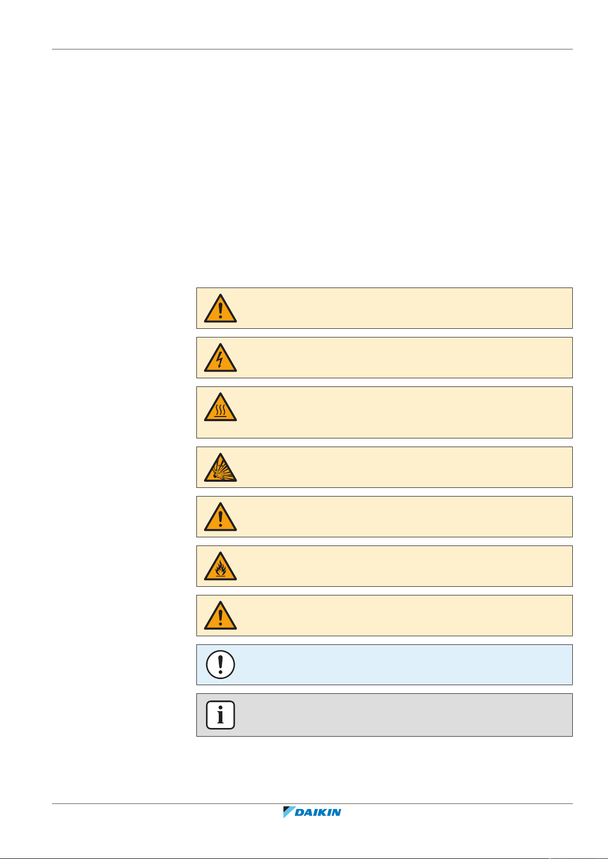
2.1.1 Meaning of warnings and symbols
DANGER
Indicates a situation that results in death or serious injury.
2 | General safety precautions
DANGER: RISK OF ELECTROCUTION
Indicates a situation that could result in electrocution.
DANGER: RISK OF BURNING/SCALDING
Indicates a situation that could result in burning/scalding because of extreme hot or
cold temperatures.
DANGER: RISK OF EXPLOSION
Indicates a situation that could result in explosion.
WARNING
Indicates a situation that could result in death or serious injury.
WARNING: FLAMMABLE MATERIAL
CAUTION
Indicates a situation that could result in minor or moderate injury.
CVXM20+FVXM25~50A2V1B
Split system air conditioners
4P625991-1A – 2020.09
NOTICE
Indicates a situation that could result in equipment or property damage.
INFORMATION
Indicates useful tips or additional information.
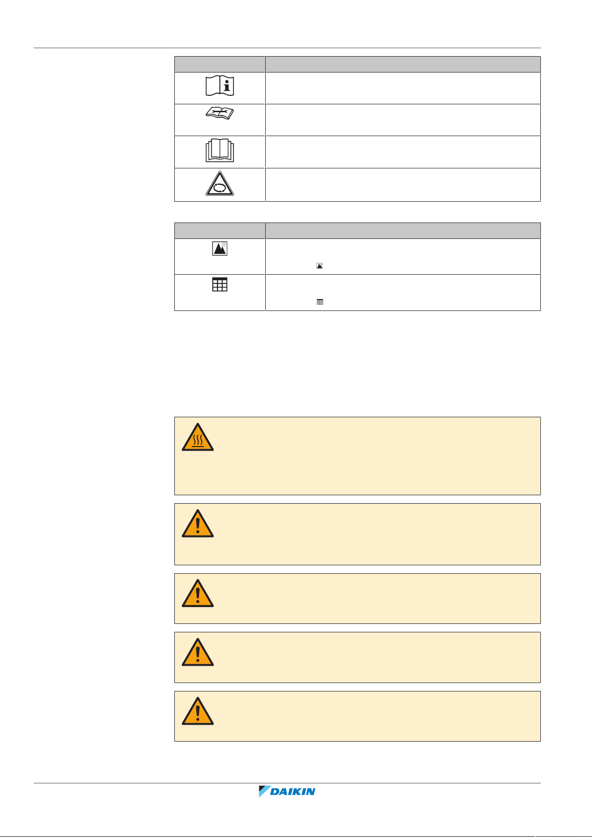
Symbols used on the unit:
Installer reference guide
5
2 | General safety precautions
Symbols used in the documentation:
Symbol Explanation
Before installation, read the installation and operation
manual, and the wiring instruction sheet.
Before performing maintenance and service tasks, read the
service manual.
For more information, see the installer and user reference
guide.
The unit contains rotating parts. Be careful when servicing or
inspecting the unit.
Symbol Explanation
Indicates a figure title or a reference to it.
Example: " 1–3 Figure title" means "Figure 3 in chapter 1".
Indicates a table title or a reference to it.
Example: " 1–3 Table title" means "Table 3 in chapter 1".
2.2 For the installer
2.2.1 General
If you are NOT sure how to install or operate the unit, contact your dealer.
DANGER: RISK OF BURNING/SCALDING
▪ Do NOT touch the refrigerant piping, water piping or internal parts during and
immediately after operation. It could be too hot or too cold. Give it time to return
to normal temperature. If you must touch it, wear protective gloves.
▪ Do NOT touch any accidental leaking refrigerant.
WARNING
Improper installation or attachment of equipment or accessories could result in
electrical shock, short-circuit, leaks, fire or other damage to the equipment. Only use
accessories, optional equipment and spare parts made or approved by Daikin.
WARNING
Make sure installation, testing and applied materials comply with applicable
legislation (on top of the instructions described in the Daikin documentation).
Installer reference guide
6
CAUTION
Wear adequate personal protective equipment (protective gloves, safety glasses,…)
when installing, maintaining or servicing the system.
WARNING
Tear apart and throw away plastic packaging bags so that nobody, especially
children, can play with them. Possible risk: suffocation.
CVXM20+FVXM25~50A2V1B
Split system air conditioners
4P625991-1A – 2020.09
2 | General safety precautions
WARNING
Provide adequate measures to prevent that the unit can be used as a shelter by small
animals. Small animals that make contact with electrical parts can cause
malfunctions, smoke or fire.
CAUTION
Do NOT touch the air inlet or aluminium fins of the unit.
CAUTION
▪ Do NOT place any objects or equipment on top of the unit.
▪ Do NOT sit, climb or stand on the unit.
NOTICE
Works executed on the outdoor unit are best done under dry weather conditions to
avoid water ingress.
In accordance with the applicable legislation, it might be necessary to provide a
logbook with the product containing at least: information on maintenance, repair
work, results of tests, stand-by periods,…
2.2.2 Installation site
Also, at least, following information MUST be provided at an accessible place at the
product:
▪ Instructions for shutting down the system in case of an emergency
▪ Name and address of fire department, police and hospital
▪ Name, address and day and night telephone numbers for obtaining service
In Europe, EN378 provides the necessary guidance for this logbook.
▪ Provide sufficient space around the unit for servicing and air circulation.
▪ Make sure the installation site withstands the weight and vibration of the unit.
▪ Make sure the area is well ventilated. Do NOT block any ventilation openings.
▪ Make sure the unit is level.
Do NOT install the unit in the following places:
▪ In potentially explosive atmospheres.
▪ In places where there is machinery that emits electromagnetic waves.
Electromagnetic waves may disturb the control system, and cause malfunction of
the equipment.
▪ In places where there is a risk of fire due to the leakage of flammable gases
(example: thinner or gasoline), carbon fibre, ignitable dust.
Instructions for equipment using R32 refrigerant
CVXM20+FVXM25~50A2V1B
Split system air conditioners
4P625991-1A – 2020.09
▪ In places where corrosive gas (example: sulphurous acid gas) is produced.
Corrosion of copper pipes or soldered parts may cause the refrigerant to leak.
▪ In bathrooms.
WARNING: MILDLY FLAMMABLE MATERIAL
The refrigerant inside this unit is mildly flammable.
Installer reference guide
7
2 | General safety precautions
WARNING
▪ Do NOT pierce or burn.
▪ Do NOT use means to accelerate the defrosting process or to clean the
equipment, other than those recommended by the manufacturer.
▪ Be aware that R32 refrigerant does NOT contain an odour.
WARNING
The appliance shall be stored so as to prevent mechanical damage and in a wellventilated room without continuously operating ignition sources (example: open
flames, an operating gas appliance or an operating electric heater) and have a room
size as specified below.
WARNING
Make sure installation, servicing, maintenance and repair comply with instructions
from Daikin and with applicable legislation (for example national gas regulation) and
are executed only by authorised persons.
WARNING
If one or more rooms are connected to the unit using a duct system, make sure:
▪ there are no operating ignition sources (example: open flames, an operating gas
appliance or an operating electric heater) in case the floor area is less than the
minimum floor area A (m²).
▪ no auxiliary devices, which may be a potential ignition source, are installed in the
duct work (example: hot surfaces with a temperature exceeding 700°C and
electric switching device);
▪ only auxiliary devices approved by the manufacturer are used in the duct work;
▪ air inlet AND outlet are connected directly to the same room by ducting. Do NOT
use spaces such as a false ceiling as a duct for the air inlet or outlet.
NOTICE
▪ Precautions shall be taken to avoid excessive vibration or pulsation to
refrigeration piping.
▪ Protection devices, piping and fittings shall be protected as far as possible against
adverse environmental effects.
▪ Provision shall be made for expansion and contraction of long runs of piping.
▪ Piping in refrigerating systems shall be designed and installed such as to minimise
the likelihood of hydraulic shock damaging the system.
▪ The indoor equipment and pipes shall be securely mounted and guarded such
that accidental rupture of equipment or pipes cannot occur from events such as
moving furniture or reconstruction activities.
CAUTION
Do NOT use potential sources of ignition in searching for or detection of refrigerant
leaks.
Installer reference guide
8
CVXM20+FVXM25~50A2V1B
Split system air conditioners
4P625991-1A – 2020.09
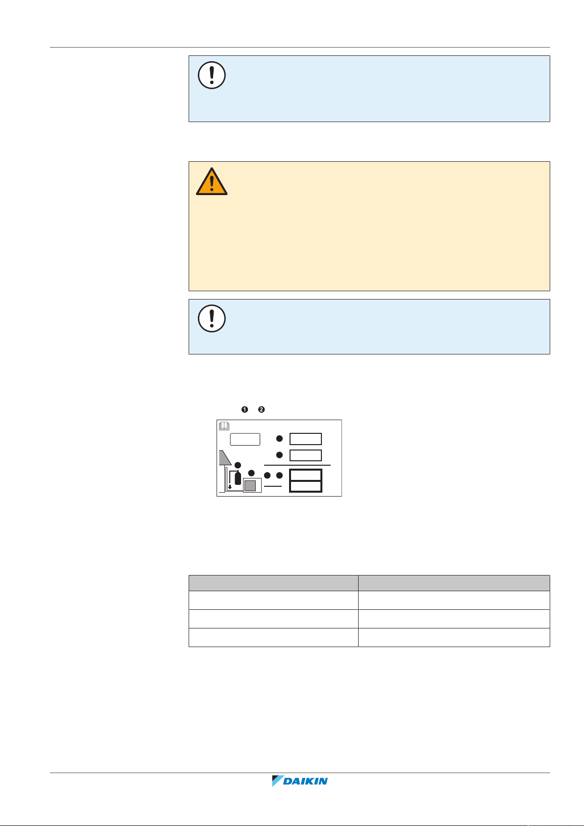
NOTICE
Contains fluorinated greenhouse gases
2
1
1
1
2
2
kg
tCO2eq
1000
GWP × kg
=
=
+
kg
=
kg
=
GWP: xxx
R32
▪ Do NOT re-use joints which have been used already.
▪ Joints made in installation between parts of refrigerant system shall be accessible
for maintenance purposes.
Installation space requirements
WARNING
If appliances contain R32 refrigerant, the floor area of the room in which the
appliances are installed, operated and stored MUST be larger than the minimum
floor area defined in table below A (m2). This applies to:
▪ Indoor units without a refrigerant leakage sensor; in case of indoor units with
refrigerant leakage sensor, consult the installation manual
▪ Outdoor units installed or stored indoors (e.g. winter garden, garage, machinery
room)
▪ Pipework in unventilated spaces
NOTICE
▪ Pipework shall be protected from physical damage.
▪ Installation of pipework shall be kept to a minimum.
2 | General safety precautions
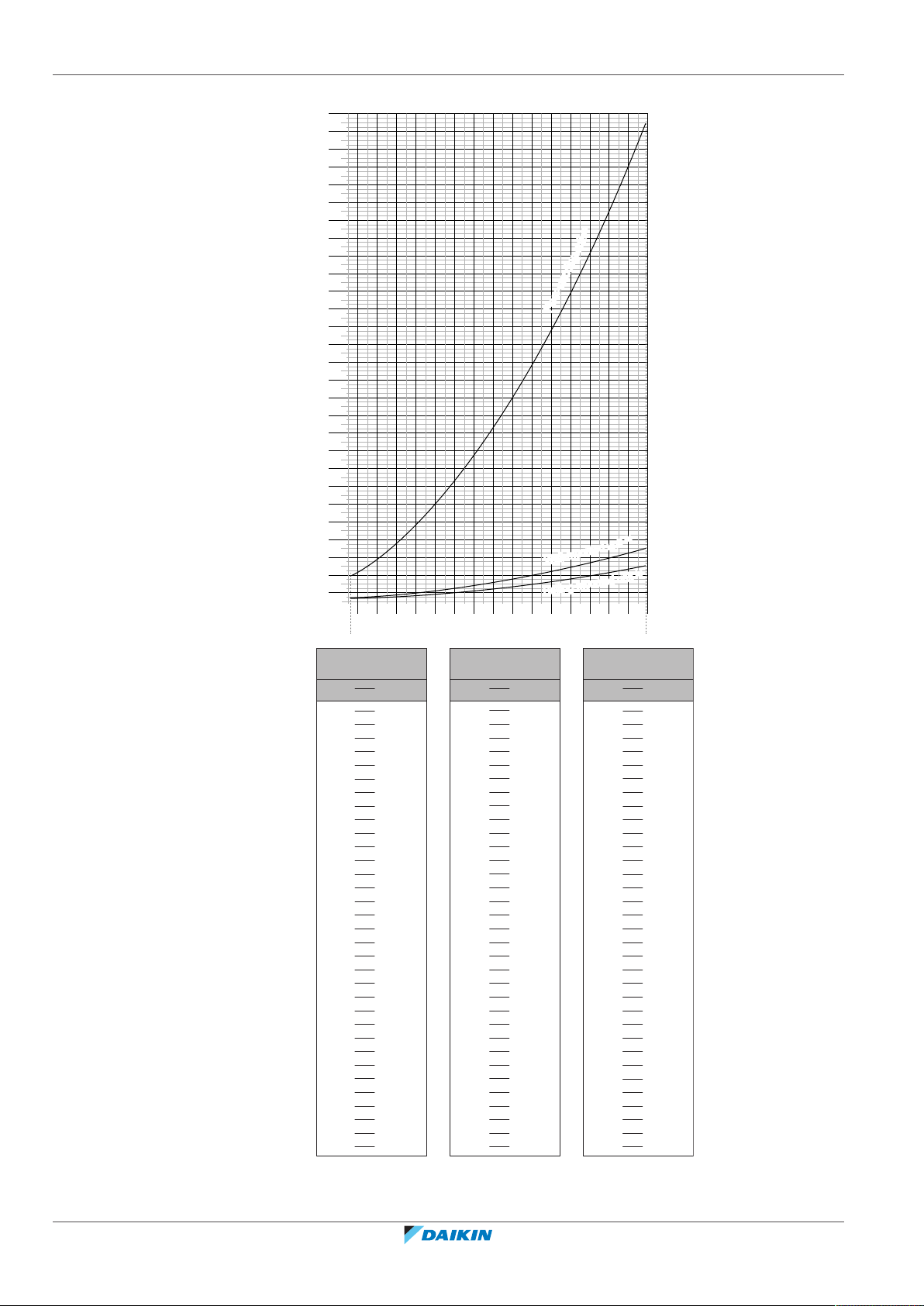
To determine the minimum floor area
1 Determine the total refrigerant charge in the system (= factory refrigerant
charge + additional refrigerant amount charged).
2 Determine which graph or table to use.
▪ For indoor units: Is the unit ceiling-mounted, wall-mounted or floor-
standing?
▪ For outdoor units installed or stored indoors, and field piping in unventilated
spaces, this depends on the installation height:
If the installation height is… Then use the graph or table for…
<1.8m Floor-standing units
1.8≤x<2.2m Wall-mounted units
≥2.2m Ceiling-mounted units
CVXM20+FVXM25~50A2V1B
Split system air conditioners
4P625991-1A – 2020.09
3 Use the graph or table to determine the minimum floor area.
Installer reference guide
9
2 | General safety precautions
0
10
20
30
40
50
60
70
80
90
100
110
120
130
140
150
160
170
180
190
200
210
220
230
240
250
260
270
280
290
300
310
320
330
340
350
360
370
380
390
400
410
420
430
440
450
460
470
480
490
500
510
520
530
540
550
1.822.2
2.4
2.6
2.833.2
3.4
3.6
3.844.2
4.4
4.6
4.855.2
5.4
5.6
5.866.2
6.4
6.6
6.877.2
7.4
7.6
7.8
1.843 7.956
8.0
A
min
(m2)
Floor-standing unit
(c)
Wall-mounted unit
(b)
Ceiling-mounted unit
(a)
m (kg)
Ceiling-mounted
unit
(a)
4.6 13.4
4.6 180
4.8 14.6
4.8 196
5.0 15.8
5.0 213
≤1.842 —
5.2 17.1
≤1.842 —
5.2 230
1.843 3.64
5.4 18.5
1.843 28.9
5.4 248
2.0 3.95
5.6 19.9
2.0 34.0
5.6 267
2.2 4.34
5.8 21.3
2.2 41.2
5.8 286
2.4 4.74
6.0 22.8
2.4 49.0
6.0 306
2.6 5.13
6.2 24.3
2.6 57.5
6.2 327
2.8 5.53
6.4 25.9
2.8 66.7
6.4 349
3.0 5.92
6.6 27.6
3.0 76.6
6.6 371
3.2 6.48
6.8 29.3
3.2 87.2
6.8 394
3.4 7.32
7.0 31.0
3.4 98.4
7.0 417
3.6 8.20
7.2 32.8
3.6 110
7.2 441
3.8 9.14
7.4 34.7
3.8 123
7.4 466
4.0 10.1
7.6 36.6
4.0 136
7.6 492
4.2 11.2
7.8 38.5
4.2 150
7.8 518
4.4 12.3
7.956 40.1
4.4 165
7.956 539
m (kg)
A
min
(m2)
4.6 20.0
4.8 21.8
5.0 23.6
≤1.842 —
5.2 25.6
1.843 4.45
5.4 27.6
2.0 4.83
5.6 29.7
2.2 5.31
5.8 31.8
2.4 5.79
6.0 34.0
2.6 6.39
6.2 36.4
2.8 7.41
6.4 38.7
3.0 8.51
6.6 41.2
3.2 9.68
6.8 43.7
3.4 10.9
7.0 46.3
3.6 12.3
7.2 49.0
3.8 13.7
7.4 51.8
4.0 15.1
7.6 54.6
4.2 16.7
7.8 57.5
4.4 18.3
7.956 59.9
Wall-mounted
unit
(b)
m (kg)
A
min
(m2)
Floor-standing
unit
(c)
m (kg)
A
min
(m2)
Installer reference guide
10
m Total refrigerant charge in the system
A
Minimum floor area
min
(a) Ceiling-mounted unit (= Ceiling-mounted unit)
CVXM20+FVXM25~50A2V1B
Split system air conditioners
4P625991-1A – 2020.09
(b) Wall-mounted unit (= Wall-mounted unit)
(c) Floor-standing unit (= Floor-standing unit)
2.2.3 Refrigerant — in case of R410A or R32
If applicable. See the installation manual or installer reference guide of your
application for more information.
NOTICE
Make sure refrigerant piping installation complies with applicable legislation. In
Europe, EN378 is the applicable standard.
NOTICE
Make sure the field piping and connections are NOT subjected to stress.
WARNING
During tests, NEVER pressurize the product with a pressure higher than the
maximum allowable pressure (as indicated on the nameplate of the unit).
2 | General safety precautions
WARNING
Take sufficient precautions in case of refrigerant leakage. If refrigerant gas leaks,
ventilate the area immediately. Possible risks:
▪ Excessive refrigerant concentrations in a closed room can lead to oxygen
deficiency.
▪ Toxic gas might be produced if refrigerant gas comes into contact with fire.
DANGER: RISK OF EXPLOSION
Pump down – Refrigerant leakage. If you want to pump down the system, and there
is a leak in the refrigerant circuit:
▪ Do NOT use the unit's automatic pump down function, with which you can collect
all refrigerant from the system into the outdoor unit. Possible consequence: Selfcombustion and explosion of the compressor because of air going into the
operating compressor.
▪ Use a separate recovery system so that the unit's compressor does NOT have to
operate.
WARNING
ALWAYS recover the refrigerant. Do NOT release them directly into the environment.
Use a vacuum pump to evacuate the installation.
CVXM20+FVXM25~50A2V1B
Split system air conditioners
4P625991-1A – 2020.09
NOTICE
After all the piping has been connected, make sure there is no gas leak. Use nitrogen
to perform a gas leak detection.
NOTICE
▪ To avoid compressor breakdown, do NOT charge more than the specified amount
of refrigerant.
▪ When the refrigerant system is to be opened, refrigerant MUST be treated
according to the applicable legislation.
Installer reference guide
11
2 | General safety precautions
▪ In case recharge is required, see the nameplate of the unit. It states the type of
refrigerant and necessary amount.
▪ The unit is factory charged with refrigerant and depending on pipe sizes and pipe
lengths some systems require additional charging of refrigerant.
▪ Only use tools exclusively for the refrigerant type used in the system, this to
ensure pressure resistance and prevent foreign materials from entering into the
system.
▪ Charge the liquid refrigerant as follows:
WARNING
Make sure there is no oxygen in the system. Refrigerant may only be charged after
performing the leak test and the vacuum drying.
Possible consequence: Self-combustion and explosion of the compressor because of
oxygen going into the operating compressor.
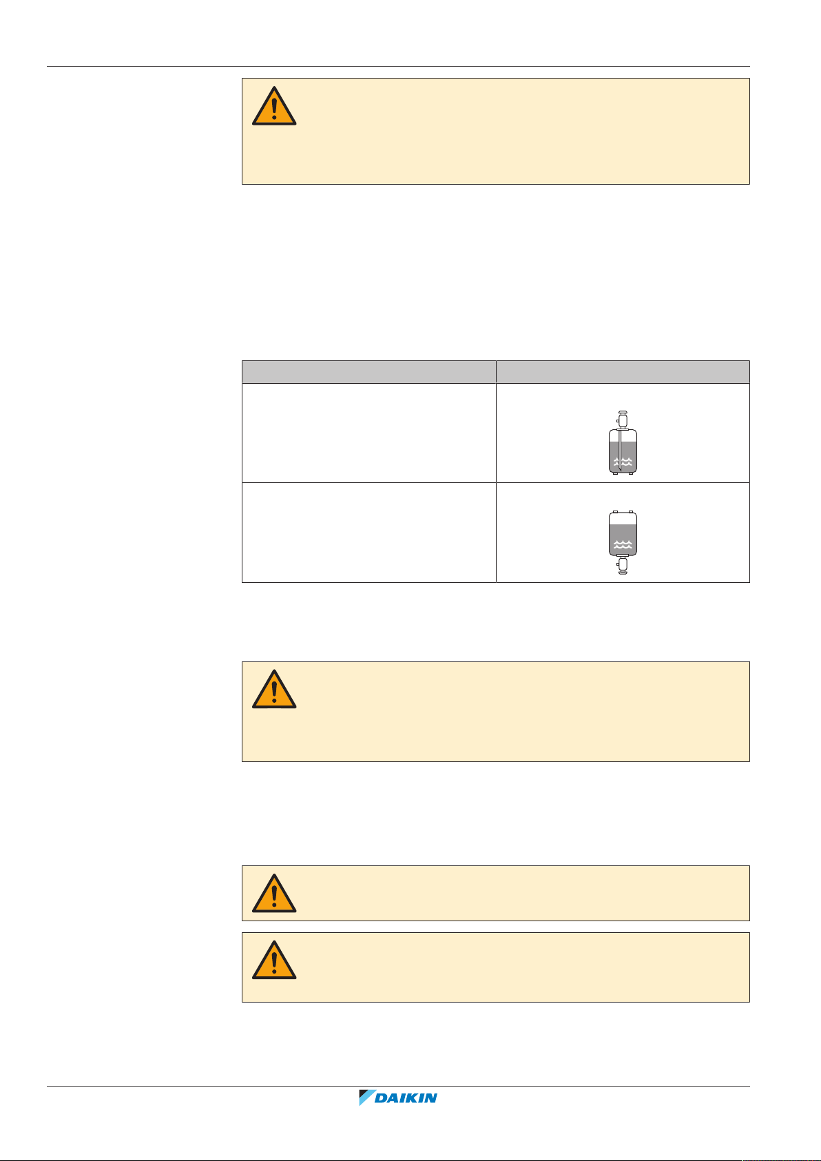
If Then
A siphon tube is present
Charge with the cylinder upright.
(i.e., the cylinder is marked with "Liquid
filling siphon attached")
A siphon tube is NOT present Charge with the cylinder upside down.
▪ Open refrigerant cylinders slowly.
▪ Charge the refrigerant in liquid form. Adding it in gas form may prevent normal
operation.
CAUTION
When the refrigerant charging procedure is done or when pausing, close the valve of
the refrigerant tank immediately. If the valve is NOT closed immediately, remaining
pressure might charge additional refrigerant. Possible consequence: Incorrect
refrigerant amount.
2.2.4 Brine
Installer reference guide
12
If applicable. See the installation manual or installer reference guide of your
application for more information.
WARNING
The selection of the brine MUST be in accordance with the applicable legislation.
WARNING
Take sufficient precautions in case of brine leakage. If brine leaks, ventilate the area
immediately and contact your local dealer.
CVXM20+FVXM25~50A2V1B
Split system air conditioners
4P625991-1A – 2020.09
2.2.5 Water
2.2.6 Electrical
2 | General safety precautions
WARNING
The ambient temperature inside the unit can get much higher than that of the room,
e.g. 70°C. In case of a brine leak, hot parts inside the unit can create a hazardous
situation.
WARNING
The use and installation of the application MUST comply with the safety and
environmental precautions specified in the applicable legislation.
If applicable. See the installation manual or installer reference guide of your
application for more information.
NOTICE
Make sure water quality complies with EU directive 98/83EC.
DANGER: RISK OF ELECTROCUTION
▪ Turn OFF all power supply before removing the switch box cover, connecting
electrical wiring or touching electrical parts.
▪ Disconnect the power supply for more than 10minutes, and measure the voltage
at the terminals of main circuit capacitors or electrical components before
servicing. The voltage MUST be less than 50VDC before you can touch electrical
components. For the location of the terminals, see the wiring diagram.
▪ Do NOT touch electrical components with wet hands.
▪ Do NOT leave the unit unattended when the service cover is removed.
WARNING
If NOT factory installed, a main switch or other means for disconnection, having a
contact separation in all poles providing full disconnection under overvoltage
categoryIII condition, MUST be installed in the fixed wiring.
CVXM20+FVXM25~50A2V1B
Split system air conditioners
4P625991-1A – 2020.09
Installer reference guide
13
2 | General safety precautions
WARNING
▪ ONLY use copper wires.
▪ Make sure the field wiring complies with the applicable legislation.
▪ All field wiring MUST be performed in accordance with the wiring diagram
supplied with the product.
▪ NEVER squeeze bundled cables and make sure they do NOT come in contact with
the piping and sharp edges. Make sure no external pressure is applied to the
terminal connections.
▪ Make sure to install earth wiring. Do NOT earth the unit to a utility pipe, surge
absorber, or telephone earth. Incomplete earth may cause electrical shock.
▪ Make sure to use a dedicated power circuit. NEVER use a power supply shared by
another appliance.
▪ Make sure to install the required fuses or circuit breakers.
▪ Make sure to install an earth leakage protector. Failure to do so may cause
electrical shock or fire.
▪ When installing the earth leakage protector, make sure it is compatible with the
inverter (resistant to high frequency electric noise) to avoid unnecessary opening
of the earth leakage protector.
CAUTION
▪ When connecting the power supply: connect the earth cable first, before making
the current-carrying connections.
▪ When disconnecting the power supply: disconnect the current-carrying cables
first, before separating the earth connection.
▪ The length of the conductors between the power supply stress relief and the
terminal block itself must be as such that the current-carrying wires are tautened
before the earth wire is in case the power supply is pulled loose from the stress
relief.
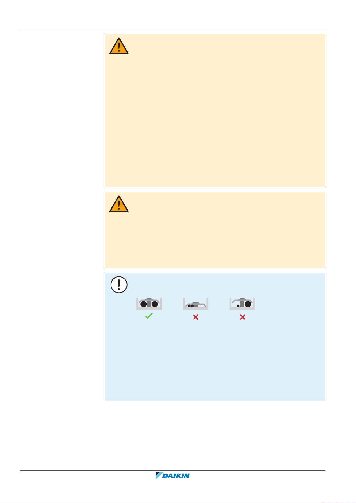
NOTICE
Precautions when laying power wiring:
▪ Do NOT connect wiring of different thicknesses to the power terminal block (slack
in the power wiring may cause abnormal heat).
▪ When connecting wiring which is the same thickness, do as shown in the figure
above.
▪ For wiring, use the designated power wire and connect firmly, then secure to
prevent outside pressure being exerted on the terminal board.
▪ Use an appropriate screwdriver for tightening the terminal screws. A screwdriver
with a small head will damage the head and make proper tightening impossible.
▪ Over-tightening the terminal screws may break them.
Installer reference guide
14
Install power cables at least 1 m away from televisions or radios to prevent
interference. Depending on the radio waves, a distance of 1 m may not be
sufficient.
CVXM20+FVXM25~50A2V1B
Split system air conditioners
4P625991-1A – 2020.09
2 | General safety precautions
WARNING
▪ After finishing the electrical work, confirm that each electrical component and
terminal inside the electrical components box is connected securely.
▪ Make sure all covers are closed before starting up the unit.
NOTICE
Only applicable if the power supply is three‑phase, and the compressor has an ON/
OFF starting method.
If there exists the possibility of reversed phase after a momentary black out and the
power goes on and off while the product is operating, attach a reversed phase
protection circuit locally. Running the product in reversed phase can break the
compressor and other parts.
CVXM20+FVXM25~50A2V1B
Split system air conditioners
4P625991-1A – 2020.09
Installer reference guide
15
3 | Specific installer safety instructions
3 Specific installer safety instructions
Always observe the following safety instructions and regulations.
Unit installation (see "6Unit installation"[423])
WARNING
The appliance shall be stored in a room without continuously operating ignition
sources (example: open flames, an operating gas appliance or an operating electric
heater).
CAUTION
For walls containing a metal frame or a metal board, use a wall embedded pipe and
wall cover in the feed-through hole to prevent possible heat, electrical shock, or fire.
Piping installation (see "7Piping installation"[435])
DANGER: RISK OF BURNING/SCALDING
CAUTION
▪ Use the flare nut fixed to the unit.
▪ To prevent gas leakage, apply refrigeration oil only to the inside of the flare. Use
refrigeration oil for R32.
▪ Do NOT reuse joints.
CAUTION
▪ Do NOT use mineral oil on flared part.
▪ NEVER install a drier to this R32 unit to guarantee its lifetime. The drying material
may dissolve and damage the system.
CAUTION
▪ Incomplete flaring may cause refrigerant gas leakage.
▪ Do NOT re-use flares. Use new flares to prevent refrigerant gas leakage.
▪ Use flare nuts that are included with the unit. Using different flare nuts may
cause refrigerant gas leakage.
Electrical installation (see "8Electrical installation"[440])
DANGER: RISK OF ELECTROCUTION
Installer reference guide
16
WARNING
▪ All wiring MUST be performed by an authorised electrician and MUST comply
with the applicable legislation.
▪ Make electrical connections to the fixed wiring.
▪ All components procured on-site and all electrical construction MUST comply
with the applicable legislation.
CVXM20+FVXM25~50A2V1B
Split system air conditioners
4P625991-1A – 2020.09
3 | Specific installer safety instructions
WARNING
▪ If the power supply has a missing or wrong N-phase, equipment might break
down.
▪ Establish proper earthing. Do NOT earth the unit to a utility pipe, surge absorber,
or telephone earth. Incomplete earthing may cause electrical shock.
▪ Install the required fuses or circuit breakers.
▪ Secure the electrical wiring with cable ties so that the cables do NOT come in
contact with sharp edges or piping, particularly on the high-pressure side.
▪ Do NOT use taped wires, stranded conductor wires, extension cords, or
connections from a star system. They can cause overheating, electrical shock or
fire.
▪ Do NOT install a phase advancing capacitor, because this unit is equipped with an
inverter. A phase advancing capacitor will reduce performance and may cause
accidents.
WARNING
ALWAYS use multicore cable for power supply cables.
WARNING
Use an all-pole disconnection type breaker with at least 3mm between the contact
point gaps that provide full disconnection under overvoltage category III.
WARNING
If the supply cord is damaged, it MUST be replaced by the manufacturer, its service
agent or similarly qualified persons in order to avoid a hazard.
WARNING
Do NOT connect the power supply to the indoor unit. This could result in electrical
shock or fire.
WARNING
▪ Do NOT use locally purchased electrical parts inside the product.
▪ Do NOT branch the power supply for the drain pump, etc. from the terminal
block. This could result in electrical shock or fire.
WARNING
Keep the interconnection wiring away from copper pipes without thermal insulation
as such pipes will be very hot.
CVXM20+FVXM25~50A2V1B
Split system air conditioners
4P625991-1A – 2020.09
Installer reference guide
17
4 | About the box
2×1×
1× 2×1× 1× 1×
2×
1×
1×
1× 2×
j k li
edb ca f
h
g
4 About the box
4.1 Indoor unit
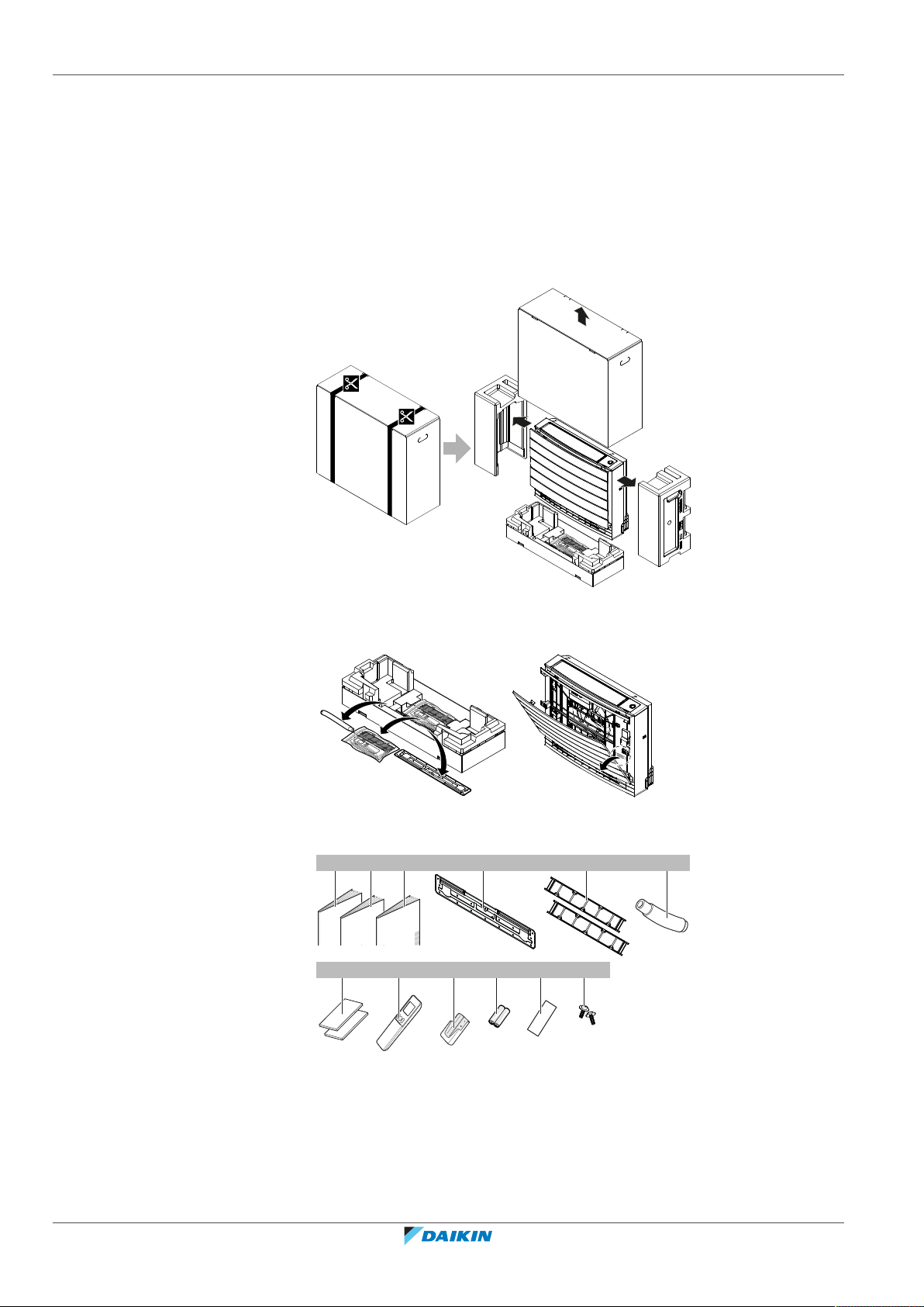
4.1.1 To unpack the indoor unit
Installer reference guide
18
4.1.2 To remove the accessories from the indoor unit
1 Remove the accessories located at the bottom of the package. Spare SSID
sticker is located on the unit.
a Installation manual
b Operation manual
c General safety precautions
d Mounting plate (attached to the unit)
e Titanium apatite deodorising filter
f Drain hose
g Insulation piece
h User interface
i User interface holder
j Dry battery AAA.LR03 (alkaline) for user interface
k Spare SSID sticker (attached to the unit)
CVXM20+FVXM25~50A2V1B
Split system air conditioners
4P625991-1A – 2020.09

4 | About the box
l Screws
▪ Spare SSID sticker. Do NOT throw away the spare sticker. Keep it in a safe place
in case it is needed in the future (e.g. in case the front grille is replaced, attach it
to the new front grille).
CVXM20+FVXM25~50A2V1B
Split system air conditioners
4P625991-1A – 2020.09
Installer reference guide
19

5 | About the unit
cba d
5 About the unit
5.1 System layout
WARNING: MILDLY FLAMMABLE MATERIAL
The refrigerant inside this unit is mildly flammable.
Following symbols may occur on the indoor unit:
Symbol Explanation
Measure the voltage at the terminals of main circuit capacitors or
electrical components before servicing.
5.2 Operation range
Use the system in the following temperature and humidity ranges for safe and
effective operation.
In combination with outdoor unit RXM25~50, 2MXM40+50, 3MXM40+52
Outdoor temperature –10~46°CDB –15~24°CDB
Indoor temperature 18~32°C DB
Indoor humidity ≤80%
(a)
(b)
a Indoor unit
b Drain piping
c Refrigerant piping (gas and liquid)
d Outdoor unit
Cooling and drying
(a)(b)
Heating
(a)
–15~18°CWB
10~30°CDB
14~23°CWB
(b)
A safety device might stop the operation of the system if the unit runs outside its
operation range.
Condensation and water dripping might occur if the unit runs outside its operation range.
—
Installer reference guide
20
In combination with outdoor unit RXTP25+35
Cooling and drying
(a)(b)
Heating
(a)
Outdoor temperature –10~46°CDB –25~24°CDB
–25~18°CWB
CVXM20+FVXM25~50A2V1B
Split system air conditioners
4P625991-1A – 2020.09

5 | About the unit
In combination with outdoor unit RXTP25+35
Cooling and drying
(a)(b)
Heating
(a)
Indoor temperature 18~32°C DB
Indoor humidity ≤80%
(a)
A safety device might stop the operation of the system if the unit runs outside its
operation range.
(b)
Condensation and water dripping might occur if the unit runs outside its operation range.
5.3 About the wireless LAN
For detailed specifications, installation instructions, setting methods, FAQ,
declaration of conformity and the latest version of this manual, visit http://
www.onlinecontroller.daikineurope.com.
INFORMATION
▪ Daikin Industries Czech Republic s.r.o. declares that the radio equipment type
inside of this unit is in compliance with Directive 2014/53/EU.
▪ This unit is considered as combined equipment according to the definition of
Directive 2014/53/EU.
14~23°CWB
(b)
10~30°CDB
—
5.3.1 Precautions when using the wireless LAN
Do NOT use near:
▪ Medical equipment. E.g. persons using cardiac pacemakers or defibrillators. This
product may cause electromagnetic interference.
▪ Auto-control equipment. E.g. automatic doors or fire alarm equipment. This
product may cause faulty behaviour of the equipment.
▪ Microwave oven. It may affect wireless LAN communications.
5.3.2 Basic parameters
What Value
Frequency range 2400MHz~2483.5MHz
Radio protocol IEEE 802.11b/g/n
Radio frequency channel 13ch
Output power 13dBm
Effective radiated power 15dBm (11b) / 14dBm (11g) / 14dBm
Power supply DC 14 V / 100 mA
(11n)
5.3.3 Setting the wireless LAN
CVXM20+FVXM25~50A2V1B
Split system air conditioners
4P625991-1A – 2020.09
The customer is responsible for providing:
▪ Smartphone or tablet with minimum supported version of Android or iOS,
specified on http://www.onlinecontroller.daikineurope.com
Installer reference guide
21

5 | About the unit
To install the Daikin Residential Controller application
▪ Internet line and communicating device, such as modem, router, etc.
▪ Wireless LAN access point.
▪ Installed free Daikin Residential Controller application.
1 Open:
▪ Google Play for appliances using Android.
▪ App Store for appliances using iOS.
2 Search for Daikin Residential Controller.
3 Follow the directions on the screen to install.
Installer reference guide
22
CVXM20+FVXM25~50A2V1B
Split system air conditioners
4P625991-1A – 2020.09

6 Unit installation
In this chapter
6.1 Preparing the installation site ................................................................................................................................................ 23
6.1.1 Installation site requirements of the indoor unit .................................................................................................. 23
6.2 Opening the indoor unit ......................................................................................................................................................... 25
6.2.1 To remove the front panel ..................................................................................................................................... 25
6.2.2 To remove the front grille ...................................................................................................................................... 25
6.2.3 To open the terminal block and remove the electrical wiring box cover ............................................................. 25
6.3 Mounting the indoor unit....................................................................................................................................................... 26
6.3.1 To install the indoor unit ........................................................................................................................................ 26
6.3.2 To drill a wall hole .................................................................................................................................................. 31
6.3.3 To remove the slit portions.................................................................................................................................... 31
6.3.4 To provide drainage ............................................................................................................................................... 32
6.4 Mounting the user interface .................................................................................................................................................. 34
6.4.1 To mount the user interface holder ...................................................................................................................... 34
6.1 Preparing the installation site
Do NOT install the unit in places often used as work place. In case of construction
works (e.g. grinding works) where a lot of dust is created, the unit MUST be
covered.
6 | Unit installation
Choose an installation location with sufficient space for carrying the unit in and out
of the site.
WARNING
The appliance shall be stored in a room without continuously operating ignition
sources (example: open flames, an operating gas appliance or an operating electric
heater).
6.1.1 Installation site requirements of the indoor unit
INFORMATION
Also read the precautions and requirements in the "2 General safety
precautions"[45].
INFORMATION
The sound pressure level is less than 70dBA.
NOTICE
The equipment described in this manual may cause electronic noise generated from
radio-frequency energy. The equipment complies to specifications that are designed
to provide reasonable protection against such interference. However, there is no
guarantee that interference will not occur in a particular installation.
It is therefore recommended to install the equipment and electric wires in such a
way that they keep a proper distance from stereo equipment, personal computers,
etc.
CVXM20+FVXM25~50A2V1B
Split system air conditioners
4P625991-1A – 2020.09
Install power cables at least 1 m away from televisions or radios to prevent
interference. Depending on the radio waves, a distance of 1 m may not be
sufficient.
Installer reference guide
23

6 | Unit installation
≤60
(65)
≤27°
(mm)
≥467
≥50 ≥50
A B
(105)
≤60
▪ Fluorescent lights. When installing a wireless user interface in a room with
fluorescent lights, mind the following to avoid interference:
- Install the wireless user interface as close as possible to the indoor unit.
- Install the indoor unit as far as possible from the fluorescent lights.
▪ Take care that in the event of a water leak, water cannot cause any damage to
the installation space and surroundings.
▪ Choose a location where the operation noise or the hot/cold air discharged from
the unit will not disturb anyone.
▪ Air flow. Make sure nothing blocks the air flow.
▪ Drainage. Make sure condensation water can be evacuated properly.
▪ Wall insulation. When conditions in the wall exceed 30°C and a relative humidity
of 80%, or when fresh air is inducted into the wall, then additional insulation is
required (minimum 10mm thickness, polyethylene foam).
▪ Wall or floor strength. Check whether the wall or the floor is strong enough to
support the weight of the unit. If there is a risk, reinforce the wall or the floor
before installing the unit.
Do NOT install the unit in the following places:
▪ In places where a mineral oil mist, spray or vapour may be present in the
atmosphere. Plastic parts may deteriorate and fall off or cause water leakage.
It is NOT recommended to install the unit in the following places because it may
shorten the life of the unit:
▪ Where the voltage fluctuates a lot
▪ In vehicles or vessels
▪ Where acidic or alkaline vapour is present
▪ In places where a mineral oil mist, spray or vapour may be present in the
atmosphere. Plastic parts may deteriorate and fall off or cause water leakage.
▪ In places where the unit would be in the path of direct sunlight.
▪ In bathrooms.
▪ Sound sensitive areas (e.g. near a bedroom), so that the operation noise will
cause no trouble.
▪ Spacing. Mind the following requirements:
Installer reference guide
24
A Front view
B Side view
▪ Do not install the unit more than 60mm above the floor.
CVXM20+FVXM25~50A2V1B
Split system air conditioners
4P625991-1A – 2020.09

6.2 Opening the indoor unit
4×
b
a
6.2.1 To remove the front panel
1 Slide both sliders in the direction of the arrows until they click.
2 Open the front panel and undo the string.
6 | Unit installation
3 Remove the front panel.
6.2.2 To remove the front grille
1 Remove the front panel. See "6.2.1To remove the front panel"[425].
2 Remove the 4 screws, remove the grill from 4 tabs on the top and remove the
front grille while pulling it toward you.
a Front grille
b Tabs
6.2.3 To open the terminal block and remove the electrical wiring box cover
CVXM20+FVXM25~50A2V1B
Split system air conditioners
4P625991-1A – 2020.09
To open the terminal block
1 Remove the front grille.
2 Remove 1 lower screw.
3 Lift the sensor securing plate.
Installer reference guide
25

6 | Unit installation
c
b
c
b
a
1
2
3
b
a
c
c
b
a
b
A B C
4 Move the metal plate cover down and then towards you to remove it.
a Screw
b Sensor securing plate
c Metal plate cover
To remove the electrical wiring box cover
1 Open the terminal block.
2 Remove 1 screw from the electrical wiring box.
3 Unhook the 2 tabs on the electrical wiring box cover and remove it.
6.3 Mounting the indoor unit
6.3.1 To install the indoor unit
Installer reference guide
26
a Screw
b Wiring box cover
c Tabs
Installation options
There are 3 possible type of installation for the indoor unit.
A Floor (exposed) installation
B Wall (exposed) installation
C Half concealed installation
a Mounting plate
b Skirting board
CVXM20+FVXM25~50A2V1B
Split system air conditioners
4P625991-1A – 2020.09

6 | Unit installation
(mm)
634.5
750
006
300
200
285
115
159
238
689
a
a
a
a
159
a
a
75
06
75
45
Ø65
Ø65
45
b
c
75
75
54
f
e
A B
C
54
45
d
6×
Floor-standing installation
6‒1 Indoor unit installation drawing: Floor-standing installation
A Front view
B Side view
C Top view
a Screw hole 6×
b Left-back piping hole location
c Right-back piping hole location
d Left/right piping hole location
e Left-bottom piping hole location
f Right-bottom piping hole location
1 Drill a wall hole, depending on which side piping is taken out. See "6.3.2 To
drill a wall hole"[431].
CVXM20+FVXM25~50A2V1B
Split system air conditioners
4P625991-1A – 2020.09
2 Open the front panel and remove the front grille (see "6.2Opening the indoor
unit"[425]).
3 Remove the slit portions using nippers. See "6.3.3 To remove the slit
portions"[431].
4 Secure the unit to the wall and floor using 6 screws M4×25L (field supply).
5 When the complete installation is finished, attach the front panel and the
front grille in their original position.
Installer reference guide
27

6 | Unit installation
82
166
06≤
(mm)
634.5
750
006
553
300
200
285
115
238
b
b
b
b
75
06
75
45
Ø65
Ø65
45
d
e
75
75
54
h
g
54
45
f
A B
C
c c
a
5×
Wall-mounted installation
6‒2 Indoor unit installation drawing: Wall-mounted installation
A Front view
B Side view
C Top view
a Mounting plate
b Screw hole 4×
c Floor
d Left-back piping hole location
e Right-back piping hole location
f Left/right piping hole location
g Left-bottom piping hole location
h Right-bottom piping hole location
6 Temporarily secure the mounting plate on the wall.
Installer reference guide
28
7 Make sure the mounting plate is level.
8 Mark the centres of the drilling points on the wall.
9 Secure the mounting plate on the wall using 5 screws M4×25L (field supply).
10 Drill a wall hole, depending on which side piping is taken out. See "6.3.2 To
drill a wall hole"[431].
11 Open the front panel and remove the front grille (see "6.2Opening the indoor
unit"[425]).
12 Remove the slit portions using nippers. See "6.3.3 To remove the slit
portions"[431].
13 If necessary for the skirting board, remove the slit portion on the bottom
frame.
CVXM20+FVXM25~50A2V1B
Split system air conditioners
4P625991-1A – 2020.09

6 | Unit installation
a
b
≤60
4×
a
a Bottom frame
b Slit portion
14 Align the unit using the alignment symbol on the mounting plate:
375 mm from the alignment symbol to the each side (unit width 750 mm),
487mm from the alignment symbol to the bottom of the unit.
15 Hook the unit on the mounting plate and secure the unit to the wall using 4
screws M4×25L (field supply).
CVXM20+FVXM25~50A2V1B
Split system air conditioners
4P625991-1A – 2020.09
a Alignment symbol
16 When the complete installation is finished, attach the front panel and the
front grille in their original position.
Installer reference guide
29

6 | Unit installation
5
4
30
f
734~740
170
350
70
200
593~595
170 350
d e
c
c
a
A B
(mm)
a
a
75
54
Ø60
Ø60
54
75
C
159
238
689
159
b b
06
75
75
54
h
g
634.5
115
285
b
b
b
b
300
6×
Half-concealed installation
6‒3 Indoor unit installation drawing: Half-concealed installation
A Front view
B Side view
C Top view
a Extra filler board
b Screw hole 6×
c Hole
d Left-back piping hole location
e Right-back piping hole location
f Right/left piping hole location
g Left-bottom piping hole location
h Right-bottom piping hole location
17 Make a hole in the wall as illustrated above.
Installer reference guide
30
18 Install the extra filler board (field supply) in accordance with the space
between the unit and the wall. Make sure there is no gap between the unit
and the wall.
19 Drill a wall hole, depending on which side piping is taken out. See "6.3.2 To
drill a wall hole"[431].
20 Remove the slit portions using nippers. See "6.3.3 To remove the slit
portions"[431].
21 Open the front panel, remove the front grille, remove the top and side casings
(see "6.2Opening the indoor unit"[425]).
22 Secure the unit to the extra filler board and to the floor using 6 screws
M4×25L (field supply).
CVXM20+FVXM25~50A2V1B
Split system air conditioners
4P625991-1A – 2020.09

23 When the complete installation is finished, attach the front panel and the
Ø65
a
b
c
a
c
d
d
b
6.3.2 To drill a wall hole
1 Bore a 65 mm large feed-through hole in the wall with a downward slope
2 Insert a wall embedded pipe into the hole.
3 Insert a wall cover into the wall pipe.
6 | Unit installation
front grille in their original position.
CAUTION
For walls containing a metal frame or a metal board, use a wall embedded pipe and
wall cover in the feed-through hole to prevent possible heat, electrical shock, or fire.
NOTICE
Be sure to seal the gaps around the pipes with sealing material (field supply), in order
to prevent water leakage.
towards the outside.
a Wall embedded pipe
b Putty
c Wall hole cover
4 After completing wiring, refrigerant piping and drain piping, do NOT forget to
seal the gap with putty.
6.3.3 To remove the slit portions
For side piping (left/right) and bottom piping (left/right) slit portions must be
removed. Remove slit portions according to where the piping is taken out.
a Bottom frame
b Slit portion for side piping on the front grille (same on the other side)
c Slit portion for side piping on the bottom frame (same of the other side)
d Slit portion for the bottom piping
1 Cut off the slit portion using nippers.
CVXM20+FVXM25~50A2V1B
Split system air conditioners
4P625991-1A – 2020.09
Installer reference guide
31

6 | Unit installation
2 Remove an burrs along the cut section using a half round needle file.
6.3.4 To provide drainage
Make sure condensation water can be evacuated properly. This involves:
▪ General guidelines
▪ Connecting the drain piping to the indoor unit
▪ Checking for water leaks
General guidelines
▪ Pipe length. Keep drain piping as short as possible. Minimum is 3m.
▪ Pipe size. Use rigid polyvinyl chloride pipe with 20 mm nominal diameter and
26mm outer diameter.
NOTICE
▪ Install the drain hose with a downward slope.
▪ Traps are NOT permitted.
▪ Do NOT put the end of the hose in water.
Installer reference guide
32
▪ Drain hose. Drain hose (accessory) is 220 mm long and with 18 mm outer
diameter on the connecting side.
▪ Extension hose. Use rigid polyvinyl chloride pipe (field supply) with 20 mm
nominal diameter as extension hose. When connecting an extension hose, use a
polyvinyl adhesive agent for glueing.
CVXM20+FVXM25~50A2V1B
Split system air conditioners
4P625991-1A – 2020.09

▪ Condensation. Take measures against condensation. Insulate the complete drain
d
1×
c
a
b
100
a
≥50
220
150
100
(mm)
c
d
b
a
piping in the building.
To connect the drain piping to the indoor unit
NOTICE
Incorrect connection of the drain hose might cause leaks, and damage the
installation space and surroundings.
1 Push the drain hose (accessory) as far as possible over the drain socket and fix
it with 1 screw (accessory).
6 | Unit installation
a Drain pan
b Drain socket
c Drain hose (accessory)
d Screw (accessory)
2 Check for water leaks (see "To check for water leaks"[433]).
3 Insulate the indoor drain socket and drain hose with ≥10 mm insulation
material to prevent condensation.
4 Connect the drain piping to the drain hose. Insert the drain hose ≥50mm, so it
will not be pulled out of the drain pipe.
a Drain hose (accessory)
b Vinyl chloride drain pipe (VP-30) (field supply)
c Reducer (field supply)
d Vinyl chloride drain pipe (VP-20) (field supply)
To check for water leaks
CVXM20+FVXM25~50A2V1B
Split system air conditioners
4P625991-1A – 2020.09
1 Remove the air filters.
2 Gradually pour approximately 1 l of water in the drain pan, and check for
water leaks.
Installer reference guide
33

6 | Unit installation
cba
2×
6.4 Mounting the user interface
6.4.1 To mount the user interface holder
a User interface
b Screws (field supply)
c User interface holder
1 Choose a place where the signal can reach the unit.
2 Fix the user interface holder (accessory) to the wall or a similar location using
2 M3×20L screws (field supply).
3 Insert the user interface into the user interface holder.
Installer reference guide
34
CVXM20+FVXM25~50A2V1B
Split system air conditioners
4P625991-1A – 2020.09

7 Piping installation
t
Ø
In this chapter
7.1 Preparing refrigerant piping................................................................................................................................................... 35
7.1.1 Refrigerant piping requirements ........................................................................................................................... 35
7.1.2 Refrigerant piping insulation.................................................................................................................................. 36
7.2 Connecting the refrigerant piping.......................................................................................................................................... 36
7.2.1 About connecting the refrigerant piping ............................................................................................................... 36
7.2.2 Precautions when connecting the refrigerant piping............................................................................................ 36
7.2.3 Guidelines when connecting the refrigerant piping.............................................................................................. 37
7.2.4 Pipe bending guidelines ......................................................................................................................................... 38
7.2.5 To flare the pipe end .............................................................................................................................................. 38
7.2.6 To connect the refrigerant piping to the indoor unit ............................................................................................ 39
7.1 Preparing refrigerant piping
7.1.1 Refrigerant piping requirements
INFORMATION
Also read the precautions and requirements in the "2 General safety
precautions"[45].
7 | Piping installation
▪ Foreign materials inside pipes (including oils for fabrication) must be
≤30mg/10m.
Refrigerant piping diameter
Use the same diameters as the connections on the outdoor units:
Class Pipe outer diameter (mm)
25+35 Ø6.4 Ø9.5
50 Ø6.4 Ø12.7
Refrigerant piping material
NOTICE
The piping and other pressure-containing parts shall be suitable for refrigerant. Use
phosphoric acid deoxidised seamless copper for refrigerant.
INFORMATION
Additional refrigerant charge is NOT allowed in case of combination of the outdoor
unit 3MXM40N8 or 3MXM52N8 with the indoor units CVXM-A and/or FVXM-A. The
total piping length MUST be ≤30m.
Liquid piping Gas piping
▪ Piping material: Phosphoric acid deoxidised seamless copper.
▪ Piping temper grade and thickness:
Outer diameter (Ø) Temper grade Thickness (t)
(a)
6.4mm (1/4") Annealed (O) ≥0.8mm
9.5mm (3/8")
12.7mm (1/2")
CVXM20+FVXM25~50A2V1B
Split system air conditioners
4P625991-1A – 2020.09
Installer reference guide
35

7 | Piping installation
ØiØ
i
t
ØpØ
p
7.1.2 Refrigerant piping insulation
(a)
Depending on the applicable legislation and the maximum working pressure of the unit
(see "PS High" on the unit name plate), larger piping thickness might be required.
▪ Use polyethylene foam as insulation material:
- with a heat transfer rate between 0.041 and 0.052 W/mK (0.035 and
0.045kcal/mh°C)
- with a heat resistance of at least 120°C
▪ Insulation thickness
Pipe outer diameter (Øp) Insulation inner diameter
6.4mm (1/4") 8~10mm ≥10mm
9.5mm (3/8") 12~15mm ≥13mm
12.7mm (1/2") 14~16mm ≥13mm
If the temperature is higher than 30°C and the humidity is higher than RH80%, the
thickness of the insulation materials should be at least 20 mm to prevent
condensation on the surface of the insulation.
7.2 Connecting the refrigerant piping
7.2.1 About connecting the refrigerant piping
Before connecting the refrigerant piping
Make sure the outdoor and indoor unit are mounted.
Insulation thickness (t)
(Øi)
Typical workflow
Connecting the refrigerant piping involves:
▪ Connecting the refrigerant piping to the indoor unit
▪ Connecting the refrigerant piping to the outdoor unit
▪ Insulating the refrigerant piping
▪ Keeping in mind the guidelines for:
- Pipe bending
- Flaring pipe ends
- Using the stop valves
7.2.2 Precautions when connecting the refrigerant piping
INFORMATION
Also read the precautions and requirements in the following chapters:
▪ General safety precautions
▪ Preparation
Installer reference guide
36
CVXM20+FVXM25~50A2V1B
Split system air conditioners
4P625991-1A – 2020.09

7 | Piping installation
DANGER: RISK OF BURNING/SCALDING
CAUTION
▪ Use the flare nut fixed to the unit.
▪ To prevent gas leakage, apply refrigeration oil only to the inside of the flare. Use
refrigeration oil for R32.
▪ Do NOT reuse joints.
CAUTION
▪ Do NOT use mineral oil on flared part.
▪ NEVER install a drier to this R32 unit to guarantee its lifetime. The drying material
may dissolve and damage the system.
NOTICE
Take the following precautions on refrigerant piping into account:
▪ Avoid anything but the designated refrigerant to get mixed into the refrigerant
cycle (e.g. air).
▪ Only use R32 when adding refrigerant.
▪ Only use installation tools (e.g. manifold gauge set) that are exclusively used for
R32 installations to withstand the pressure and to prevent foreign materials (e.g.
mineral oils and moisture) from mixing into the system.
▪ Install the piping so that the flare is NOT subjected to mechanical stress.
▪ Protect the piping as described in the following table to prevent dirt, liquid or
dust from entering the piping.
▪ Use caution when passing copper tubes through walls (see figure below).
7.2.3 Guidelines when connecting the refrigerant piping
CVXM20+FVXM25~50A2V1B
Split system air conditioners
4P625991-1A – 2020.09
Unit Installation period Protection method
Outdoor unit >1month Pinch the pipe
<1month Pinch or tape the pipe
Indoor unit Regardless of the period
INFORMATION
Do NOT open the refrigerant stop valve before checking the refrigerant piping. When
you need to charge additional refrigerant it is recommended to open the refrigerant
stop valve after charging.
Take the following guidelines into account when connecting pipes:
▪ Coat the flare inner surface with ether oil or ester oil when connecting a flare
nut. Tighten 3 or 4 turns by hand, before tightening firmly.
Installer reference guide
37

7 | Piping installation
a
b
c
d
R=
0.4~0.8
±2
45°
90°
±2
ØA
a b
A
▪ ALWAYS use 2 wrenches together when loosening a flare nut.
▪ ALWAYS use a spanner and torque wrench together to tighten the flare nut when
connecting the piping. This to prevent nut cracking and leaks.
a Torque wrench
b Spanner
c Piping union
d Flare nut
Piping size (mm) Tightening torque
(N•m)
Flare dimensions
(A) (mm)
Flare shape (mm)
Ø6.4 15~17 8.7~9.1
Ø9.5 33~39 12.8~13.2
Ø12.7 50~60 16.2~16.6
7.2.4 Pipe bending guidelines
Use a pipe bender for bending. All pipe bends should be as gentle as possible
(bending radius should be 30~40 mm or larger).
7.2.5 To flare the pipe end
1 Cut the pipe end with a pipe cutter.
2 Remove burrs with the cut surface facing down so that the chips do NOT enter
the pipe.
CAUTION
▪ Incomplete flaring may cause refrigerant gas leakage.
▪ Do NOT re-use flares. Use new flares to prevent refrigerant gas leakage.
▪ Use flare nuts that are included with the unit. Using different flare nuts may
cause refrigerant gas leakage.
Installer reference guide
38
a Cut exactly at right angles.
b Remove burrs.
3 Remove the flare nut from the stop valve and put the flare nut on the pipe.
4 Flare the pipe. Set exactly at the position as shown in the following figure.
CVXM20+FVXM25~50A2V1B
Split system air conditioners
4P625991-1A – 2020.09

7 | Piping installation
a b
c
a
b
c
d
a
b
a
a
e
b
e
c
b
a
d
c
d
b
Flare tool for R32
(clutch type)
A 0~0.5mm 1.0~1.5mm 1.5~2.0mm
5 Check that the flaring is properly made.
a Flare’s inner surface MUST be flawless.
b The pipe end MUST be evenly flared in a perfect circle.
c Make sure the flare nut is fitted.
7.2.6 To connect the refrigerant piping to the indoor unit
WARNING: MILDLY FLAMMABLE MATERIAL
The refrigerant inside this unit is mildly flammable.
▪ Pipe length. Keep refrigerant piping as short as possible. Minimum is 3m.
Conventional flare tool
Clutch type
(Ridgid-type)
Wing nut type
(Imperial-type)
1 Connect refrigerant piping to the unit using flare connections.
2 Insulate the refrigerant piping on the indoor unit as follows:
a Gas pipe
b Gas pipe insulation
c Liquid pipe
d Liquid pipe insulation
NOTICE
Make sure to insulate all refrigerant piping. Any exposed piping might cause
condensation.
3 Close the slit on the refrigerant pipe connection and secure it with a tape
(field supply). Make sure there are no gaps.
4 Wrap the slit and the end of the insulation of the connected refrigerant piping
with insulation piece (accessory). Make sure there are no gaps.
CVXM20+FVXM25~50A2V1B
Split system air conditioners
4P625991-1A – 2020.09
a Refrigerant pipe connection
b Refrigerant piping (field supply)
c Slit
d Tape
e Insulation piece (accessory)
Installer reference guide
39

8 | Electrical installation
8 Electrical installation
In this chapter
8.1 About connecting the electrical wiring
8.1 About connecting the electrical wiring .................................................................................................................................. 40
8.1.1 Precautions when connecting the electrical wiring .............................................................................................. 40
8.1.2 Guidelines when connecting the electrical wiring ................................................................................................ 41
8.1.3 Specifications of standard wiring components ..................................................................................................... 42
8.2 To connect the electrical wiring to the indoor unit ............................................................................................................... 42
8.3 To connect optional accessories (wired user interface, central user interface, wireless adapter, etc.).............................. 43
Typical workflow
Connecting the electrical wiring typically consists of the following stages:
1 Making sure the power supply system complies with the electrical
specifications of the units.
2 Connecting the electrical wiring to the outdoor unit.
3 Connecting the electrical wiring to the indoor unit.
4 Connecting the main power supply.
8.1.1 Precautions when connecting the electrical wiring
DANGER: RISK OF ELECTROCUTION
WARNING
ALWAYS use multicore cable for power supply cables.
INFORMATION
Also read the precautions and requirements in the "2 General safety
precautions"[45].
INFORMATION
Also read "8.1.3Specifications of standard wiring components"[442].
WARNING
▪ All wiring MUST be performed by an authorised electrician and MUST comply
with the applicable legislation.
▪ Make electrical connections to the fixed wiring.
▪ All components procured on-site and all electrical construction MUST comply
with the applicable legislation.
Installer reference guide
40
CVXM20+FVXM25~50A2V1B
Split system air conditioners
4P625991-1A – 2020.09

8 | Electrical installation
b a
WARNING
▪ If the power supply has a missing or wrong N-phase, equipment might break
down.
▪ Establish proper earthing. Do NOT earth the unit to a utility pipe, surge absorber,
or telephone earth. Incomplete earthing may cause electrical shock.
▪ Install the required fuses or circuit breakers.
▪ Secure the electrical wiring with cable ties so that the cables do NOT come in
contact with sharp edges or piping, particularly on the high-pressure side.
▪ Do NOT use taped wires, stranded conductor wires, extension cords, or
connections from a star system. They can cause overheating, electrical shock or
fire.
▪ Do NOT install a phase advancing capacitor, because this unit is equipped with an
inverter. A phase advancing capacitor will reduce performance and may cause
accidents.
WARNING
Use an all-pole disconnection type breaker with at least 3mm between the contact
point gaps that provide full disconnection under overvoltage category III.
WARNING
If the supply cord is damaged, it MUST be replaced by the manufacturer, its service
agent or similarly qualified persons in order to avoid a hazard.
WARNING
Do NOT connect the power supply to the indoor unit. This could result in electrical
shock or fire.
WARNING
▪ Do NOT use locally purchased electrical parts inside the product.
▪ Do NOT branch the power supply for the drain pump, etc. from the terminal
block. This could result in electrical shock or fire.
WARNING
Keep the interconnection wiring away from copper pipes without thermal insulation
as such pipes will be very hot.
8.1.2 Guidelines when connecting the electrical wiring
Keep the following in mind:
CVXM20+FVXM25~50A2V1B
Split system air conditioners
4P625991-1A – 2020.09
▪ If stranded conductor wires are used, install a round crimp-style terminal on the
end of the wire. Place the round crimp-style terminal on the wire up to the
covered part and fasten the terminal with the appropriate tool.
a Stranded conductor wire
b Round crimp-style terminal
▪ Use the following methods for installing wires:
Installer reference guide
41

8 | Electrical installation
c b
c
aa
A
AA´
A´
c b ba c
a
B
B
1-3
Wire type Installation method
Single-core wire
a Curled single-core wire
b Screw
c Flat washer
Stranded conductor wire
with round crimp-style
terminal
a Terminal
b Screw
c Flat washer
Allowed
NOT allowed
▪ The earth wire between the wire retainer and the terminal must be longer than
the other wires.
8.1.3 Specifications of standard wiring components
Component
Interconnection cable (indoor↔outdoor) 4-core cable 1.5mm²~2.5mm²
andapplicable for 220~240V
8.2 To connect the electrical wiring to the indoor unit
1 Open the terminal block. See "6.2Opening the indoor unit"[425].
2 Strip the wire ends approximately 15mm.
H05RN-F (60245 IEC 57)
Installer reference guide
42
3 Match wire colours with terminal numbers on indoor and outdoor unit’s
terminal blocks and firmly screw wires to the corresponding terminals.
4 Connect the earth wires to the corresponding terminals.
CVXM20+FVXM25~50A2V1B
Split system air conditioners
4P625991-1A – 2020.09

8 | Electrical installation
a
b
c
a
b
a Terminal block
b Electrical component block
c Cable clamp
5 Pull the wires to make sure that they are securely attached, then retain the
wires with the cable clamp.
6 Make sure that the wires do not come in contact with the metal parts of the
heat exchanger.
7 In case of connecting to an optional adapter, see "8.3 To connect optional
accessories (wired user interface, central user interface, wireless adapter,
etc.)"[443].
8.3 To connect optional accessories (wired user interface, central user interface, wireless adapter, etc.)
1 Remove the electrical wiring box cover. See "6.2 Opening the indoor
unit"[425].
2 Connect the optional adapter wire to the S21 connector. To connect the
optional adapter wire to the option, refer to the installation manual of the
optional adapter.
3 Lead the wire as shown in the figure below.
CVXM20+FVXM25~50A2V1B
Split system air conditioners
4P625991-1A – 2020.09
a S21connector
B Optional adapter wire
Installer reference guide
43

8 | Electrical installation
4 Close the electrical wiring box cover. See "9.2 To close the indoor
unit"[445].
Installer reference guide
44
CVXM20+FVXM25~50A2V1B
Split system air conditioners
4P625991-1A – 2020.09

9 | Finishing the indoor unit installation
a
b
c
e
f
9 Finishing the indoor unit installation
9.1 To finish the indoor unit installation
1 After the drain piping, refrigerant piping and the electrical wiring are finished.
Wrap the refrigerant pipes and the interconnection cable with insulation tape.
Overlap at least half the width of the tape with each turn.
a Interconnection cable
b Gas pipe
c Gas pipe insulation
d Insulation tape
e Liquid pipe
f Liquid pipe insulation
2 Pass the pipes through the wall hole and seal the gaps with putty.
3 Remove the protection foil from the Daikin eye.
INFORMATION
Be careful when removing the protection foil to avoid damage of the sticker under it.
9.2 To close the indoor unit
9.2.1 To close the electrical wiring box and close the terminal block
1 Hook the electrical wiring box onto the 2 tabs, close it, and fix it with 1 screw.
2 Attach the front metal cover and fix it with the screw.
3 Close the sensor securing plate.
9.2.2 To re-install the front grille
1 Attach the front grille to the original position.
2 Secure the front grille with the 4 screws and 4 tabs.
9.2.3 To re-install the front panel
1 Insert the front panel into the grooves of the unit (3 places) and attach the
string.
CVXM20+FVXM25~50A2V1B
Split system air conditioners
4P625991-1A – 2020.09
Installer reference guide
45

9 | Finishing the indoor unit installation
2 Close the front panel and slide both sliders until they click.
3 Push on the sides of the front panel to make sure the front panel is securely
fixed.
Installer reference guide
46
CVXM20+FVXM25~50A2V1B
Split system air conditioners
4P625991-1A – 2020.09

10 Configuration
a
10.1 To set a different address
In case 2 indoor units are installed in 1 room, different addresses for 2 user
interfaces can be set.
1 Remove the cover and the batteries from the user interface.
2 Cut the address jumper J4.
Address jumper J4 Address
Factory setting 1
After cutting with nippers 2
10 | Configuration
a Address jumper J4
NOTICE
Be careful NOT to damage any of the surrounding parts when cutting the address
jumper.
3 Turn the power supply on.
4 Press the middle of and simultaneously.
5 Press , select and press .
Result: The Daikin eye will start to blink.
6 Press the indoor unit ON/OFF switch while the Daikin eye is blinking.
INFORMATION
If the setting could NOT be completed while the Daikin eye was blinking, repeat the
setting process from the beginning.
CVXM20+FVXM25~50A2V1B
Split system air conditioners
4P625991-1A – 2020.09
Installer reference guide
47

10 | Configuration
7 When the setting is complete, press .
Result: The user interface will return to the home screen.
Installer reference guide
48
CVXM20+FVXM25~50A2V1B
Split system air conditioners
4P625991-1A – 2020.09

11 Commissioning
11.1 Overview: Commissioning
This chapter describes what you have to do and know to commission the system
after it is installed.
Typical workflow
Commissioning typically consists of the following stages:
1 Checking the "Checklist before commissioning".
2 Performing a test run for the system.
11.2 Checklist before commissioning
After the installation of the unit, first check the items listed below. Once all checks
are fulfilled, the unit must be closed. Power-up the unit after it is closed.
You read the complete installation instructions, as described in the installer reference
guide.
The indoor units are properly mounted.
11 | Commissioning
The outdoor unit is properly mounted.
Air inlet/outlet
Check that the air inlet and outlet of the unit is NOT obstructed by paper sheets,
cardboard, or any other material.
There are NO missing phases or reversed phases.
The refrigerant pipes (gas and liquid) are thermally insulated.
Drainage
Make sure drainage flows smoothly.
Possible consequence: Condensate water might drip.
The system is properly earthed and the earth terminals are tightened.
The fuses or locally installed protection devices are installed according to this document,
and have NOT been bypassed.
The power supply voltage matches the voltage on the identification label of the unit.
The specified wires are used for the interconnection cable.
The indoor unit receives the signals of the user interface.
There are NO loose connections or damaged electrical components in the switchbox.
CVXM20+FVXM25~50A2V1B
Split system air conditioners
4P625991-1A – 2020.09
The insulation resistance of the compressor is OK.
There are NO damaged components or squeezed pipes on the inside of the indoor and
outdoor units.
There are NO refrigerant leaks.
The correct pipe size is installed and the pipes are properly insulated.
Installer reference guide
49

11 | Commissioning
11.3 To perform a test run
11.3.1 To perform a test run using the user interface
The stop valves (gas and liquid) on the outdoor unit are fully open.
Prerequisite: Power supply MUST be in the specified range.
Prerequisite: Test run may be performed in cooling or heating mode.
Prerequisite: Test run should be performed in accordance with the operation
manual of the indoor unit to make sure that all functions and parts are working
properly.
1 In cooling mode, select the lowest programmable temperature. In heating
mode, select the highest programmable temperature. Test run can be
disabled if necessary.
2 When the test run is finished, set the temperature to a normal level. In cooling
mode: 26~28°C, in heating mode: 20~24°C.
3 The system stops operating 3minutes after the unit is turned OFF.
1 Press to switch the system on.
2 Press the middle of and simultaneously.
3 Press twice to choose and confirm selection by pressing .
Result: on the display indicates that the test run is selected. Test run operation
will stop automatically after about 30 minutes.
4 To stop operation sooner, press the ON/OFF button.
Installer reference guide
50
CVXM20+FVXM25~50A2V1B
Split system air conditioners
4P625991-1A – 2020.09

12 Hand-over to the user
Once the test run is finished and the unit operates properly, please make sure the
following is clear for the user:
▪ Make sure that the user has the printed documentation and ask him/her to keep
it for future reference. Inform the user that he can find the complete
documentation at the URL mentioned earlier in this manual.
▪ Explain the user how to properly operate the system and what to do in case of
problems.
▪ Show the user what to do for the maintenance of the unit.
12 | Hand-over to the user
CVXM20+FVXM25~50A2V1B
Split system air conditioners
4P625991-1A – 2020.09
Installer reference guide
51

13 | Disposal
13 Disposal
NOTICE
Do NOT try to dismantle the system yourself: dismantling of the system, treatment of
the refrigerant, oil and other parts MUST comply with applicable legislation. Units
MUST be treated at a specialised treatment facility for reuse, recycling and recovery.
Installer reference guide
52
CVXM20+FVXM25~50A2V1B
Split system air conditioners
4P625991-1A – 2020.09

14 Technical data
,
A
INDOOR
OUTDOOR
▪ A subset of the latest technical data is available on the regional Daikin website
(publicly accessible).
▪ The full set of latest technical data is available on the Daikin Business Portal
(authentication required).
14.1 Wiring diagram
14.1.1 Unified wiring diagram legend
For applied parts and numbering, refer to the wiring diagram on the unit. Part
numbering is by Arabic numbers in ascending order for each part and is
represented in the overview below by "*" in the part code.
Symbol Meaning Symbol Meaning
Circuit breaker Protective earth
14 | Technical data
Connection Protective earth (screw)
Connector
Rectifier
Earth Relay connector
Field wiring Short-circuit connector
Fuse Terminal
Indoor unit Terminal strip
Outdoor unit Wire clamp
Residual current
device
Symbol Colour Symbol Colour
BLK Black ORG Orange
BLU Blue PNK Pink
BRN Brown PRP, PPL Purple
GRN Green RED Red
GRY Grey WHT White
CVXM20+FVXM25~50A2V1B
Split system air conditioners
4P625991-1A – 2020.09
YLW Yellow
Symbol Meaning
A*P Printed circuit board
BS* Pushbutton ON/OFF, operation switch
BZ, H*O Buzzer
C* Capacitor
Installer reference guide
53

14 | Technical data
Symbol Meaning
AC*, CN*, E*, HA*, HE*, HL*, HN*, HR*,
Connection, connector
MR*_A, MR*_B, S*, U, V, W, X*A,
K*R_*, NE
D*, V*D Diode
DB* Diode bridge
DS* DIP switch
E*H Heater
FU*, F*U, (for characteristics, refer to
Fuse
PCB inside your unit)
FG* Connector (frame ground)
H* Harness
H*P, LED*, V*L Pilot lamp, light emitting diode
HAP Light emitting diode (service monitor
green)
HIGH VOLTAGE High voltage
IES Intelligent eye sensor
IPM* Intelligent power module
K*R, KCR, KFR, KHuR, K*M Magnetic relay
L Live
L* Coil
L*R Reactor
M* Stepper motor
M*C Compressor motor
M*F Fan motor
M*P Drain pump motor
M*S Swing motor
MR*, MRCW*, MRM*, MRN* Magnetic relay
N Neutral
n=*, N=* Number of passes through ferrite core
PAM Pulse-amplitude modulation
PCB* Printed circuit board
PM* Power module
PS Switching power supply
Installer reference guide
54
PTC* PTC thermistor
Q* Insulated gate bipolar transistor (IGBT )
Q*C Circuit breaker
Q*DI, KLM Earth leak circuit breaker
Q*L Overload protector
CVXM20+FVXM25~50A2V1B
Split system air conditioners
4P625991-1A – 2020.09

14 | Technical data
Symbol Meaning
Q*M Thermo switch
Q*R Residual current device
R* Resistor
R*T Thermistor
RC Receiver
S*C Limit switch
S*L Float switch
S*NG Refrigerant leak detector
S*NPH Pressure sensor (high)
S*NPL Pressure sensor (low)
S*PH, HPS* Pressure switch (high)
S*PL Pressure switch (low)
S*T Thermostat
S*RH Humidity sensor
S*W, SW* Operation switch
SA*, F1S Surge arrester
SR*, WLU Signal receiver
SS* Selector switch
SHEET METAL Terminal strip fixed plate
T*R Transformer
TC, TRC Transmitter
V*, R*V Varistor
V*R Diode bridge, Insulated-gate bipolar
transistor (IGBT) power module
WRC Wireless remote controller
X* Terminal
X*M Terminal strip (block)
Y*E Electronic expansion valve coil
Y*R, Y*S Reversing solenoid valve coil
Z*C Ferrite core
CVXM20+FVXM25~50A2V1B
Split system air conditioners
4P625991-1A – 2020.09
ZF, Z*F Noise filter
Installer reference guide
55

15 | Glossary
15 Glossary
Dealer
Sales distributor for the product.
Authorised installer
Technical skilled person who is qualified to install the product.
User
Person who is owner of the product and/or operates the product.
Applicable legislation
All international, European, national and local directives, laws, regulations
and/or codes that are relevant and applicable for a certain product or
domain.
Service company
Qualified company which can perform or coordinate the required service to
the product.
Installation manual
Instruction manual specified for a certain product or application, explaining
how to install, configure and maintain it.
Operation manual
Instruction manual specified for a certain product or application, explaining
how to operate it.
Maintenance instructions
Instruction manual specified for a certain product or application, which
explains (if relevant) how to install, configure, operate and/or maintain the
product or application.
Accessories
Labels, manuals, information sheets and equipment that are delivered with
the product and that need to be installed according to the instructions in
the accompanying documentation.
Optional equipment
Equipment made or approved by Daikin that can be combined with the
product according to the instructions in the accompanying documentation.
Field supply
Equipment NOT made by Daikin that can be combined with the product
according to the instructions in the accompanying documentation.
Installer reference guide
56
CVXM20+FVXM25~50A2V1B
Split system air conditioners
4P625991-1A – 2020.09


Verantwortung für Energie und Umwelt
Copyright 2020 Daikin
4P625991-1A 2020.09
 Loading...