


MODELS
BRC4C82
INSTALLATION MANUAL
Wireless Remote Controller Kit
Read these instructions carefully before installation.
Keep this manual in a handy place for future reference.
This manual should be left with the equipment owner.

Wireless Remote Controller Kit Installation manual
CONTENTS
1. SAFETY CONSIDERATIONS.......................................... 2
2. BEFORE INSTALLATION ................................................ 2
3. REMOTE CONTROLLER INSTALLATION ...................... 2
4. RECEIVER INSTALLATION............................................. 3
5. FIELD SETTING .............................................................. 6
6. TEST OPERATION.......................................................... 6
1. SAFETY CONSIDERATIONS
Please read these “SAFETY CONSIDERATIONS” carefully
before installing air conditioning equipment and be sure to
install it correctly. After completing the installation, make sure
that the unit operates properly during the start-up operation.
Please instruct the customer on how to operate the unit and
keep it maintained.
Also, inform customers that they should store this installation
manual along with the operation manual for future reference.
This air conditioner comes under the term “appliances not
accessible to the general public”.
Meaning of warning, caution and note symbols.
WARNING ............. Indication a potentially hazardous sit-
uation which, if not avoided, could
result in death or serious injury.
CAUTION ..............Indication a potentially hazardous sit-
uation which, if not avoided, may
result in minor or moderate injury. It
may also be sued to alert against
unsafe practices.
NOTE .................... Indication situation that may result in
equipment or property-damage-only
accidents.
WARNING
• Perform installation work in accordance with this installation manual.
Improper installation may result in electric shocks or fire.
• Be sure to use only the specified accessories and parts
for installation work.
Failure to use the specified parts may result in, electric
shocks, fire or the unit falling.
• Before touching electrical parts, turn off the unit.
• Do not touch the switch with wet fingers.
Touching a switch with wet fingers can cause electric shock.
• The installation position of this receiver is one corner of
the decoration panel. Therefore, confirm that its position
is set so that the signal from the wireless remote controller can be easily transmitted and its display can be easily
seen.
• If both this kit and fresh air intake kit are installed, only
one duct chamber shall be used. Refer to the installation
manual of the fresh air intake kit (optional hand book).
2. BEFORE INSTALLATION
2-1 ACCESSORIES
Check if the following accessories are included with the unit.
(2)
Name (1) Receiver
Quantity 1 pc. 1 pc. 1 pc.
Shape
Name
Quantity 2 pcs. 1 pc. 2 pcs.
Shape
Name
Quantity 2 pcs. 2 pcs. 1 pc.
Shape
Name (10) Winged bar
Quantity 1 pc. 1 pc. 1 pc.
Shape
(4) Dry cell battery
LR03 (AM4)
(7) Mounting
screw (Black)
M4
Wireless remote
controller
(5) Unit No. label
1
2
1
2
1
2
(8) Mounting
screw
M5
(11) Operation
manual
3
3
3
(3)
Remote
controller holder
(6)
Screw for install-
ing remote controller hol
der
M3.5
(9) Paper pattern
printing
3-15/16×1-15/16 (in.)
(12) Installation
manual
CAUTION
• Refer also to the installation manuals attached to the
indoor unit and the decoration panel.
• Confirm that the following conditions are satisfied prior
to installation.
Ensure that nothing interrupts the operation of the wireless
remote controller. (Ensure that there is neither a source of
light nor fluorescent lamp near the receiver. Also, ensure that
the receiver is not exposed of direct sunlight.)
Ensure that the operation display lamp and other indicators
are easy to see.
2-2 NOTE TO THE INSTALLER
Be sure to instruct the customer how to properly operate the
system showing him/her the attached operation manual.
3. REMOTE CONTROLLER INSTALLATION
<Installing wireless remote controller>
• Do not throw the remote controller or impose large shocks.
Also, do not store where it may be exposed to moisture or
direct sunlight.
2
• When operating, point the transmitting part of the remote
controller in the direction of the receiver.
• The direct transmitting distance of the remote controller is
approximately 23 ft..
• The signal cannot be transmitted if something such as curtains blocks the receiver and the remote controller.
• Installing to a wall or a pillar
1. Fix the remote controller holder (3) with
the screws (6).
2. Slide the remote controller (2) into the
remote controller holder (3) from the top.
• How to put the dry cell batteries
1. Remove the back cover of the remote con-
troller (2) to the direction pointed by the
arrow mark.
2. Put the dry cell batteries.
Use two LR03<AM4> dry cell batteries (4).
Put the dry cell batteries (4) correctly to fit
their (+) and (–).
3. Close the back cover as before.
4. RECEIVER INSTALLATION
CAUTION
• Do not install more than 3 receivers in the vicinity of one
another.
• With 4 or more units, there is always the possibility of malfunction.
4-1. Preparations before installation
Remove the upper part of the receiver (1).
• Insert the screwdriver (–) here and gently work off the
upper part of the receiver (1).
Upper part
Receiver (1)
Lower part
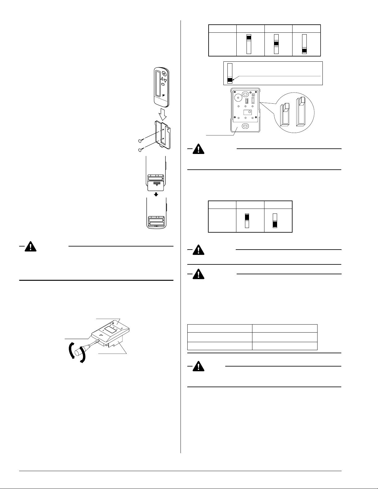
Unit No.
Wireless
address
switch
(SS2)
No.1 No.2 No.3
1
2
3
1
2
3
1
2
3
The side painted black indicates
the switch knob position.
1
M
2
S
3
Lower part
CAUTION
Change the setting so that the internal electronic equipments
are not damaged with a pen etc.
When using both a wired and a wireless remote controller
for 1 indoor unit, the wired controller should be set to MAIN.
Therefore, set the MAIN/SUB switch (SS1) of the receiver
to SUB.
MAIN SUB
MAIN/
SUB
switch
(SS1)
M
S
M
S
4-4. Receiver installation
WARNING
Be sure to turn off the power before installation.
CAUTION
<Precautions on transmission wiring>
1. When wiring, run the wiring away the power supply wiring in
order to avoid receiving electric noise (external noise).
2. When wiring, refer to the wiring diagram of indoor unit
(attached to indoor unit) as well.
WIRING SPECIFICATION
Wiring type Sheathed wire (2 wire)
Size
Wiring length Max 650 ft. (See Note)
AWG18-16
4-2. Determination of address and MAIN/SUB remote con-
troller
If setting multiple wireless remote controllers to operate in
1 room, perform address setting for the receiver and the
wireless remote controller. If setting multiple wired remote
controllers in 1 room, change the MAIN/SUB switch of the
receiver.
4-3. Setting procedure
• Setting the receiver
Set the wireless address switch (SS2) on the PC-board
according to the table below.
3
NOTE
Keep wires to less than 650 ft. total when using 2 remote controllers (wired or wireless) and when not.
 Loading...