

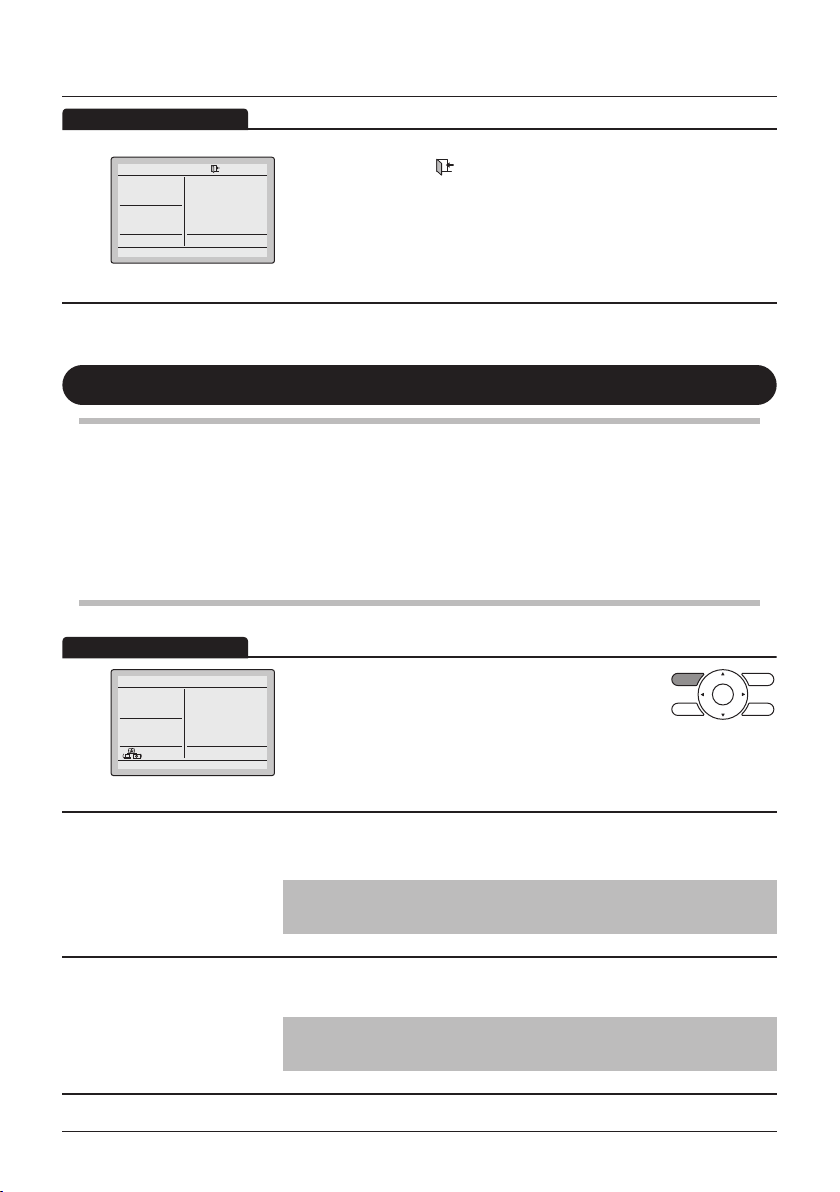
WIRED REMOTE
CONTROLLER
USER REFERENCE GUIDE
BRC1E53
• Thank you for purchasing the wired remote controller.
• This manual describes safety precautions required for the use of the
product.
Read this manual carefully and be sure you understand the
information provided before attempting to use the product.
Keep this manual where it is readily accessible after reading it through.
If another user operates the product in the future, be sure to hand over
this manual to the new user.

Contents
Notices
Basic Operation Method
Quick Reference of
Main Menu Items
Menu Manipulation
Safety Precautions ................................................... 2
Items to be Strictly Observed ................................... 3
Names and Functions...............................................7
Liquid Crystal Display ............................................... 9
Cool/Heat/Auto/Fan Operation ............................... 13
Program Dry Operation .......................................... 17
Setback...................................................................18
Ventilation Operation .............................................. 19
Setting the Cooling/Heating Selection Eligibility ..... 20
Key Lock .................................................................23
The Main Menu Items Overview. ............................ 24
Main Menu ..............................................................29
Airow Direction......................................................30
Individual Air Direction ............................................ 31
Quick Start ..............................................................35
Ventilation ............................................................... 36
Energy Saving Options ...........................................38
Schedule.................................................................46
Filter Auto Clean ..................................................... 51
Maintenance Information ........................................ 52
Conguration .......................................................... 53
Current Settings......................................................58
Clock & Calendar....................................................59
Language................................................................61
Maintenance
Reference Information
User reference guide BRC1E53
4P419251-1 – 2015.10
1
Reset Filter Indication .............................................62
Maintenance of Unit and the LCD display .............. 63
Error Code Display ................................................. 64
After-sale Service ................................................... 65
Safety Precautions
The original instructions are written in English. All other languages are translations of the original
instructions.
This appliance is not intended to be used by persons, including children, with reduced physical,
sensory or mental capabilities or lack of experience and knowledge, unless they are supervised or
have been given instructions on how to use the appliance by a person responsible for their safety.
Childen should be supervised to ensure that they do not play with the appliance.
Please read these Safety Precautions carefully before installing the remote controller.
• This manual classifies the precautions into WARNING and CAUTION.
They both contain important information regarding safety. Be sure to follow all the precautions
below.
WARNING
CAUTION
• The following pictograms are used in this manual.
Never do. Always follow the instructions given.
Be sure to ground the unit. Absolutely keep wet hands away.
Absolutely keep water and moisture
away.
Failure to follow these instructions properly may result in personal
injury or loss of life.
Failure to observe these instructions properly may result in property
damage or personal injury, which may be serious depending on the
circumstances.
About Remote Controller
WARNING
• Do not install the remote controller by yourself.
Improper installation may result in electric shocks or re.
Consult your Daikin dealer.
• Do not modify or repair the remote controller.
This may result in electric shocks or re.
Consult your Daikin dealer.
• Do not relocate or reinstall the remote controller by yourself.
Improper installation may result in electric shocks or re.
Consult your Daikin dealer.
• Do not use ammable materials (e.g., hairspray or insecticide) near the
product.
Do not clean the product with organic solvents such as paint thinner.
The use of organic solvents may cause crack damage to the product, electric shocks or
re.
BRC1E53 User reference guide
4P419251-1 – 2015.10
2
Items to be Strictly Observed
CAUTION
• Do not play with the unit or its remote controller.
Accidental operation by a child may result in impairment of bodily functions and harm
health.
• Never disassemble the remote controller.
Touching the interior parts may result in electric shocks or re.
Consult your Daikin dealer or authorized contractor for internal inspections and
adjustments.
• To avoid electric shocks, do not operate with wet hands.
• Do not wash the remote controller.
Doing so may cause electric leakage and result in electric shocks or re.
• Do not leave the remote controller wherever there is a risk of wetting.
If water gets into the remote controller there is a risk of electrical leakage and damage to
electronic components.
Indoor Unit and Outdoor Unit
WARNING
• Be aware that prolonged, direct exposure to cool or warm air from the air
conditioner or to air that is too cold or too warm can be harmful to your
physical condition and health.
• Do not place objects, including rods, your ngers, etc. in the air inlet or
outlet.
Injury may result due to contact with the air conditioner's highspeed fan blades.
• Contact professional personnel about attachment of accessories and be
sure to use only accessories specied by the manufacturer.
If a defect results from your own workmanship, it may result in water leaks, electric
shock or re.
• Do not use the product in atmospheres contaminated with oil vapor,
such as cooking oil or machine oil vapor.
Oil vapor may cause crack damage, electric shocks or re.
• Do not use the product in places with excessive oily smoke, such as
cooking rooms or in places with ammable gas, corrosive gas or metal
dust.
Using the product in such places may cause re or product failures.
• Beware of re in case of refrigerant leakage.
If the air conditioner is not operating correctly, i.e. not generating cool or warm air,
refrigerant leakage could be the cause. Consult your dealer for assistance. The
refrigerant within the air conditioner is safe and normally does not leak. However, in the
event of a leakage, contact with a naked burner, heater or cooker may result in
generation of noxious gas. Do not longer use the air conditioner until a qualied service
person conrms that the leakage has been repaired.
User reference guide BRC1E53
4P419251-1 – 2015.10
3
Items to be Strictly Observed
WARNING
• In the case of using a load breaker provided with a fuse, make sure that
the capacity of the fuse is correct.
Use of an ordinary conductive wire may cause malfunctions or re.
• Do not use the power supply breaker to start or stop the air conditioner.
Otherwise, re or water leakage may result.
Furthermore, the fan will rotate abruptly if power failure compensation is enabled, which
may result in injury.
• Be sure to earth the unit.
Do not earth the unit to a utility pipe, lightning conductor or telephone earth lead.
Imperfect earthing may result in electric shocks or re. A high surge current from
lightning or other sources may cause damage to the air conditioner.
• When the air conditioner is malfunctioning (giving off a burning odour,
etc). turn off the power and contact your local dealer.
Continued operation under such circumstances may result in a failure, electric shocks or
re hazards.
• Consult your local dealer regarding what to do in case of refrigerant
leakage.
When the air conditioner is to be installed in a small room, it is necessary to take proper
measures so that the amount of any leaked refrigerant does not exceed the
concentration limit in the event of a leakage.
Otherwise, this may lead to an accident due to oxygen depletion.
• Be sure to install an earth leakage breaker.
Failure to install an earth leakage breaker may result in electric shocks or re.
• Consult the dealer if the air conditioner submerges owing to a natural
disaster such as a ood or typhoon.
Do not operate the air conditioner in that case or otherwise a malfunction, electric shock
or re may result.
• Be sure to use a dedicated power supply for the air conditioner.
The use of any other power supply may cause heat generation, re or product failures.
BRC1E53 User reference guide
4P419251-1 – 2015.10
4
Items to be Strictly Observed
• After prolonged use, check the unit stand and its mounts for damage.
If left in a damaged condition, the unit may fall and cause injury.
• Do not allow a child to mount on the outdoor unit or avoid placing any
object on it.
Falling or tumbling may result in injury.
• Do not block air inlets nor outlets.
Impaired airow may result in insufcient performance or trouble.
• To avoid injury, do not touch the air inlet or aluminium ns of the unit.
• Do not remove the outdoor unit's fan guard.
The guard protects against the unit's high speed fan, which may cause injury.
• Do not place objects that are susceptible to moisture directly beneath
the indoor or outdoor units.
Under certain conditions, condensation on the main unit or refrigerant pipes, air lter dirt
or drain blockage may cause dripping, resulting in fouling or failure of the object
concerned.
• Do not place water containers (ower vases, etc). on the unit, as this
may result in electric shocks or re.
• Do not use the air conditioner for purposes other than those for which it
is intended.
Do not use the air conditioner for cooling precision instruments, food, plants, animals or
works of art as this may adversely affect the performance, quality and/or longevity of the
object concerned.
• Do not place appliances that produce naked ames in places exposed to
the airow from the unit as this may impair combustion of the burner.
CAUTION
• Do not place heaters directly below the unit as resulting heat can cause
deformation.
• Be sure that children, plants or animals are not exposed directly to
airow from the unit as adverse effects may ensue.
• Do not put ammable containers, such as spray cans, within 1m from the
blow-off mouth.
The containers may explode because the warm air output of the indoor or outdoor unit
will affect them.
• Do not install the air conditioner at any place where there is a danger of
ammable gas leakage.
In the event of a gas leakage, build-up of gas near the air conditioner may result in re
hazards.
User reference guide BRC1E53
4P419251-1 – 2015.10
5
Items to be Strictly Observed
CAUTION
• Do not sit or stand on any unstable base at the time of operating or
maintaining the air conditioner.
The base may topple down and injury may occur.
• Do not touch the motor when replacing the lter.
The motor can be very hot which may result in burns.
• Do not wash the air conditioner with water as this may result in electric
shocks or re.
• Perform ventilation from time to time.
Be careful when using the air conditioner with other heating equipment.
Insufcient ventilation may result in oxygen deciency.
• Always stop the operation of the air conditioner and turn OFF the power
supply breaker when cleaning.
Failure to do so may result in an electric shock or injury.
• Do not wash the interior of the indoor and outdoor units by yourself.
Always consult your Daikin dealer.
The use of an incorrect washing method or incorrect detergent may damage the resin
parts of the indoor unit or cause water leakage.
Moreover, malfunctions, smoke generation or ignition may result if the electric parts or
the motor in the indoor unit come in contact with a detergent or water.
• Do not place objects in direct proximity of the outdoor unit and do not let
leaves and other debris accumulate around the unit.
Leaves are a hotbed for small animals which can enter the unit. Once in the unit, such
animals can cause malfunctions, smoke or re when making contact with electrical
parts.
• Fix the units securely.
If the units are not mounted securely, the units may fall or topple and result in personal
injury.
• Arrange the drain to ensure complete drainage.
If proper drainage from the outdoor drain pipe does not occur during air conditioner
operation, there could be a blockage due to dirt and debris build-up in the pipe.
This may result in water leakage from the indoor unit. Under these circumstances, stop
the air conditioner operation and consult your dealer for assistance.
BRC1E53 User reference guide
4P419251-1 – 2015.10
6
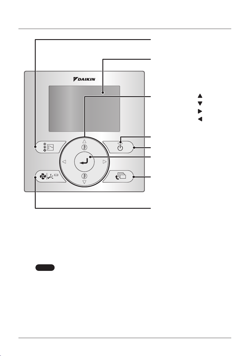
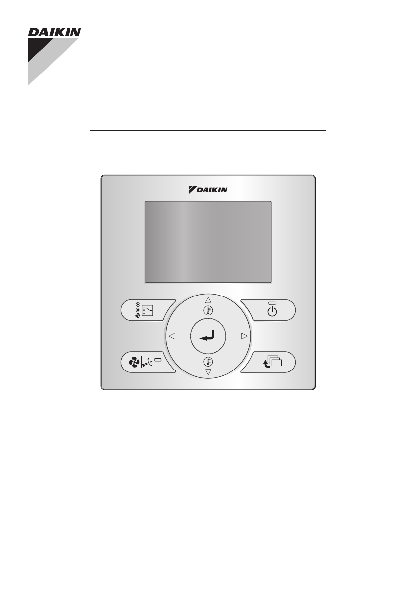
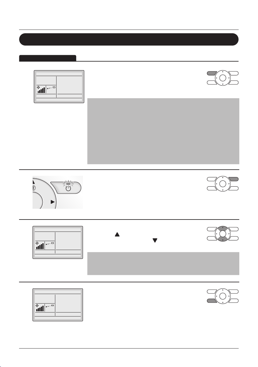
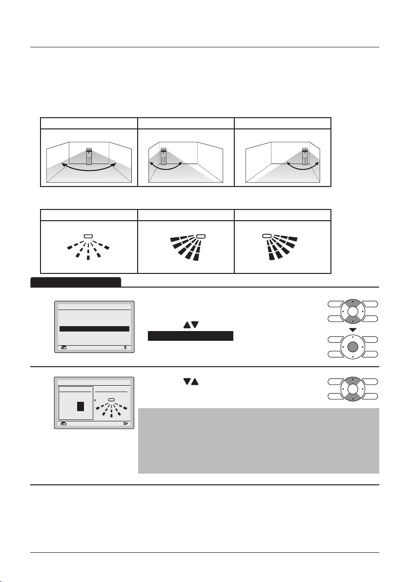
Names and Functions
1. Operation Mode
Selector button
11. LCD (with backlight)
4. Up button
5. Down button
6. Right button
7. Left button
9. Operation lamp
8. ON/OFF button
3. Menu/Enter button
10. Cancel button
2. Fan Speed/Airow
Direction button
Functions other than the basic operation items (i.e., ON/OFF,
operation mode selection, fan speed/airow direction and
temperature settings) are set from the menu screen.
NOTE
• Do not install the remote controller in places exposed to direct sunlight.
Otherwise, the LCD may become discolored and nothing may be displayed.
• Do not pull or twist the remote controller cord.
Otherwise, the remote controller may malfunction.
• Do not press the buttons on the remote controller with objects with sharp ends.
Otherwise, the remote controller may be damaged or malfunction.
User reference guide BRC1E53
4P419251-1 – 2015.10
7
Names and Functions
1. Operation Mode Selector button
• Press this button to select the operation
mode of your preference. (See "Cool/Heat/
Auto/Fan Operation" on page 13)
• Available modes may vary with the
connected model.
2. Fan Speed/Airow Direction
button
• Used to change the fan speed and airow
direction.
• Available fan speeds may vary with the
connected model.
3. Menu/Enter button
• Used to display the Main Menu or enter the
selected item (See "The Main Menu Items
Overview." on page 24).
4. Up button
• Used to raise the set temperature.
• The next item on the upper side will be
highlighted.
(Keep pressing the button to cycle through
the values or items).
• Used to change the selected item.
5. Down button
• Used to lower the set temperature.
• The next item on the lower side will be
highlighted.
(Keep pressing the button to cycle through
the values or items).
• Used to change the selected item.
7. Left button
• Used to highlight the next items on the
left-hand side.
• The display contents are changed to the
previous screen.
8. ON/OFF button
• Press to start or stop the air conditioner.
9. Operation lamp (Green)
• This lamp lights up during operation.
• This lamp is not lit when the unit operation
is OFF.
• This lamp blinks if an error occurs.
10. Cancel button
• Used to return to the previous screen.
11. LCD (with backlight)
• The backlight will be lit for approximately
30 seconds when one of the buttons is
pressed.
• The actions linked to the buttons , except
for the ON/OFF button, are not carried out
when the backlight is not lit.
• When two remote controllers are used to
control a single indoor unit, the backlight of
the remote controller which is operated rst
will be lit.
• The Auto Display Off function allows for the
display to turn off automatically after a set
period of time (see "Auto Display Off" on
page 44).
6. Right button
• Used to highlight the next items on the
right-hand side.
• The display contents are changed to the
next screen.
BRC1E53 User reference guide
4P419251-1 – 2015.10
8
Names and Functions
12
18
13
12
15
21
20
19
2
14
13
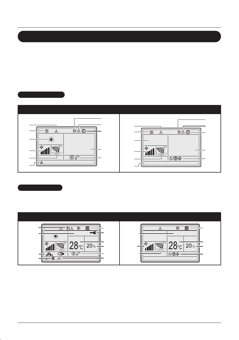
Liquid Crystal Display
• There are two display methods for the liquid crystal display (LCD) available. The
Standard display, which is used by default, and the Detailed display.
• To change the active display method, select the desired display method in the Display
Mode screen (See "Display" on page 56).
• The displayed contents on the screen may vary with the operation mode of the
connected models. (E.g.: The following display will appear when the air conditioner is
in automatic heating operation).
Standard display
With icons With icons and text (default)
10
17
1
2
Detailed display
28°C
16
8
3
21
10
17
1
2
13
Error: Push Menu button
5
Heat
Set to
28°C
The clock and Detailed selection items appear on the Detailed
display in addition to the items appearing on the Standard display.
With icons With icons and text
11
14
Fr i
:
11
03
6
9
7
3
Heat
Error: Push Menu button
Fr i
:
11
03
Set to Room
9
3
15
4
16
8
3
4
User reference guide BRC1E53
4P419251-1 – 2015.10
9
1. Operation mode
• Indicates the current operation mode.
Operation Mode
Cool Heat Vent Air Clean
Fan Dry Auto (Cool) Auto (Heat)
2. Fan speed
• Indicates the fan speed that is set for the
air conditioner.
• The fan speed will not be displayed if the
air conditioner does not have the fan speed
control function.
3. Set/Setback temperature display
• When the unit is turned ON, the
temperature that is set for the air
conditioner is displayed.
• When the unit is turned OFF and Setback
is disabled, the temperature that is set for
the air conditioner is displayed.
• When the unit is turned OFF and Setback
is enabled, the temperature that is set for
the setback function is displayed.
• By default, the display method is Dual
Setpoint mode. For instructions on how to
enable Single Setpoint mode, refer to the
installer reference guide.
4. Defrost/Hot start " "
• Indicates that Defrost/Hot start operation is
active.
• The Defrost/Hot start operation is only
possible when a Heat Reclaim Ventilation
(HRV) unit is connected. For details, refer
to the Operation Manual of the Heat
Reclaim Ventilation unit.
Names and Functions
– If a number of indoor units are in
operation, the message will appear only
if none of the indoor units is provided
with the corresponding function, i.e., the
message will not appear if at least one of
the indoor units is provided with the
corresponding function.
• Error: Press Menu Button.
• Warning: Press Menu Button.
– Displayed when an error or a warning is
detected.
• Quick Start (Sky Air only)
– Displayed when the Quick Start function
is active.
• Time to clean lter
• Time to clean element
• Time to clean lter and element
– Displayed when the time has come to
clean the lter and/or element.
6. Ventilation/Purifying
• The Ventilation mode icons." "
Indicate the current ventilation mode
(AUTOMATIC, ENERGY RECLAIM
VENTILATION, BYPASS).
• Air purication icon " " indicates that the
(optional) air purication kit is operational.
7. Key lock " "
• Displayed when key lock is active.
8. Timer enabled " "
• Indicates that the schedule timer or the
OFF timer is enabled.
9. Timer problem " "
• Indicates that the clock needs to be set
again.
• The schedule timer function will not work
unless the clock is set again.
5. Message
The following messages can be displayed:
• This function not available.
– Displayed for a few seconds when an
operation button is pressed if the indoor
unit is not provided with the
corresponding function.
BRC1E53 User reference guide
4P419251-1 – 2015.10
10. Centralised control " "
• Indicates that the air conditioner is under
the management of central control
equipment (optional accessories) and the
operation of the system through the remote
controller is prohibited.
10
Names and Functions
11. Changeover under centralised
control " "
• Indicates that the changeover of the
installation is under centralised control
assigned to another indoor unit, or an
optional cool/ heat selector connected to
the outdoor unit (= master remote
controller).
12. Setback " "
• Indicates that the clock is set.
• If the clock is not set, " -- : -- " is displayed.
13. Airow direction
• Displayed when the airow direction and
swing are set.
• This item is not displayed if the system is
not provided with a function to set airow
directions.
14. Clock (12/24 hours real time clock)
• Indicates that the clock is set.
• If the clock is not set, " -- : -- " is displayed.
15. Detailed selection
• Is displayed when the detailed display
mode is selected.
• No detailed items are selected by default.
18. Error " "
• Indicates a unit error or warning.
19. Clean lter " "
• Indicates that the time to clean the lter has
come.
20. Clean element " "
• Indicates that the time to clean the element
has come.
21. Self-cleaning lter operation
" "
• Indicates that the self-cleaning lter is busy
operating.
16. Rotation " "
• Indicates one unit is set as back-up and
rotation is enabled.
17. Low noise operation/power
consumption limitation/forced
thermo off (BACnet) " "
• Indicates that the system is running under
low noise operation or under power
consumption limitation conditions, or
receives a forced 'thermo off' command
from a BACnet interface. Refer to the
service manual of the outdoor unit or
contact your local dealer.
User reference guide BRC1E53
4P419251-1 – 2015.10
11
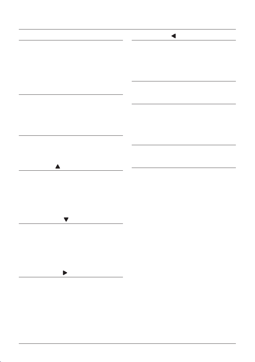
Operation Method
Button display
Displays the positions
Screen display
Screens that will be
displayed on the
remote controller.
Basic Operation Method
Remote Controller
Functions
Main Menu
Airflow Direction
Individual Air Direction
Quick Start
Ventilation
Energy Saving Options
1
Schedule
Schedule
Clock has not been set.
Would you like to set it now?
2
Date & Time
Year 2016
Month 01
Day 01
Friday
0:00
Return Setting
SettingReturn
NoYes
SettingReturn
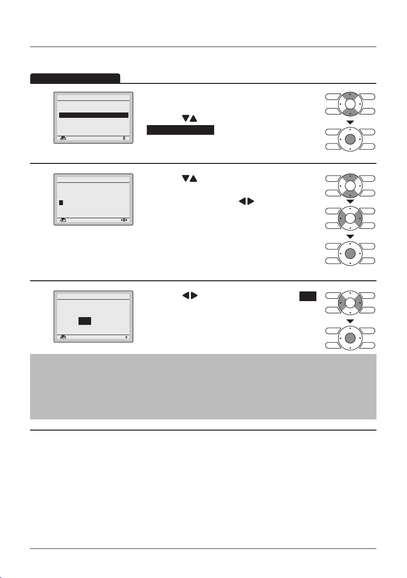
Operation procedure
Operate the buttons according to
the procedure.
• Display the Main Menu. (See "Manipulating
1/2
the Main Menu" on page 29).
• Press the
select Schedule and press the Menu/Enter
button.
• Press the (Left/Right) buttons to
select Yes and press the Menu/Enter
button.
• The Date & Time screen will appear.
• Set the current year, month, day, and time.
(See "Clock & Calendar" on page 59).
Note
• Before setting the schedule, the clock must
be set.
• If the clock has not been set, a screen like
the one on the left will appear.
(Up/Down) buttons to
of the buttons to be
operated.
Preparation
• For mechanical protection purposes, turn ON the system at least 6 hours before starting the
operation of the system.
• Do not turn OFF the system in-season in order to ensure the smooth starting of the system.
BRC1E53 User reference guide
4P419251-1 – 2015.10
12
Basic Operation Method
Operation Method
Cool/Heat/Auto/Fan Operation
• Press the Operation Mode Selector button several
1
Cool
Set to
times until the desired mode (Cooling, Heating, Fan
Only, Dry or Auto) is selected.
28°C
Note
• Unavailable operation modes are not displayed.
• Only Cooling, Dry or Fan Only mode can be selected if the air
conditioner is a cooling-only model.
• Before making a mode change, make sure that Changeover
under control is not displayed on the remote controller.
The cooling or heating mode cannot be selected if the above is
displayed on the remote controller. See "Setting the Cooling/
Heating Selection Eligibility" on page 20 if the Changeover
under control icon blinks.
• Press the ON/OFF button.
2
The Operation lamp (green) will be lit and the air
conditioner will start operating.
(SkyAir and VRV)
• The set temperature will increase by 1°C
3
4
Cool
Cool
Set to
28°C
Set to
when the (Up) button is pressed and
decrease by 1°C when the (Down) button
is pressed.
Note
Temperature settings are not possible while in Dry or Fan Only
mode.
• To change the fan speed or airow direction, press
the Fan Speed/Airow Direction button.
28°C
User reference guide BRC1E53
4P419251-1 – 2015.10
13
Basic Operation Method
Low
0
0
2
4
Airflow level /direction
level Direction1
Lv. 1 (L)
Return
Return
Auto
High
Airflow level /direction
Air Volume/dire ction
Air Volume Direc tion
Return Setting
Swing stop
Setting
Medium-low
Medium
Medium-high
level Direction1
Lv. 1 (L)
Return Setting
High
Return Setting
Swing stop
SettingReturn
Swing
Airow direction
setting (up/down)
Air Volume/dire ction
Air Volume Direc tion
High
Return Setting
Swing
Airow direction
setting (left/right)
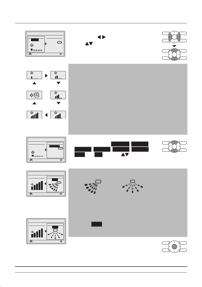
• To select the airow level or airow direction
setting, press (Left/Right) buttons.
• Press
(Up/Down) buttons to select the
desired level or position.
Note
• The air conditioner may be in automatic fan speed control for
mechanical protection purposes.
• The air conditioner may be in automatic fan speed control
according to the room temperature.
• The fan may stop operating, which is not a failure.
•
It may take time until fan speed changes are actually carried out.
• In Auto mode, the fan speed is adjusted automatically according
to the setpoint and indoor temperature
• In case of Fan Only mode the fan speed is high.
• Depending on the type of indoor unit, there are two fan speeds
(low and high), three fan speeds (low, medium and high) or ve
fan speeds available (low, medium-low, medium, medium-high,
high). Some indoor units also support automatic fan speed.
• With airow direction selected, select the desired
airow direction from No Ind Set, Position 0,
Position 1, Position 2, Position 3, Position 4,
Swing, and Auto using the (Up/Down)
buttons.
Note
• Airow direction appears on the screen as below.
0 : Position 0
1
2
3
Up/down direction
1
3
Left/right direction
1 : Position 1
2 : Position 2
3 : Position 3
4 : Position 4
• Selecting one of the 5 positions (0 to 4) makes the airow
direction blades stay in a xed position.
• Selecting Swing makes the airow direction blades swing back
and forth.
• Pressing Menu/Enter button conrms the
settings and takes you back to the basic
screen
BRC1E53 User reference guide
4P419251-1 – 2015.10
14

Basic Operation Method
• When the ON/OFF button is pressed again, the air
5
conditioner will stop operating and the Operation
lamp will turn OFF.
Note
• When the system is stopped while in heating operation, the fan
will continue to operate for approximately 1 minute in order to
eliminate the residual heat in the indoor unit.
• To prevent water leakage or system failure, do not turn OFF the
power soon after the air conditioner stops operating. Be sure to
wait at least 5 minutes so that the drain pump nishes
discharging the residual water from the indoor unit.
Characteristics of Cooling Operation
• If the cooling operation is used when the room temperature is too low,
frost forms on the heat exchanger of the indoor unit which can
decrease the cooling capacity. In this case, the air conditioner
automatically switches to defrost operation for a while.
During defrost operation, a low airow rate or a gentle wind is used to
prevent the discharge of melt water. (The remote controller displays the
fan speed that is set).
• When the outdoor air temperature is high, it takes some time until the
room temperature reaches the set temperature.
Characteristics of Heating Operation
Starting operation
User reference guide BRC1E53
4P419251-1 – 2015.10
15
• Heating operation generally requires a longer time to attain the set
temperature compared with cooling operation.
It is recommended to start operating the air conditioner in advance by
using the timer.

Basic Operation Method
Perform the following operation in order to prevent the degradation of the
heating capability or cold drafts.
Defrost operation
Hot start (VRV
only)
Outdoor
temperature and
heating capability
• The air conditioner will automatically go into defrost operation to
prevent frost accumulation at the outdoor unit which results in loss of
the heating capacity.
• The indoor unit fan will stop, and " " (Defrost/Hot start) will be
displayed on the remote controller.
• The air conditioner will return to normal operation after approximately
6 to 8 minutes (Max 10 minutes).
• When the air conditioner goes into heating operation or defrost
operation, the indoor unit fan will stop in order to prevent a cold draft.
(In that case, " " (Defrost/Hot start) will be displayed on the
remote controller).
• The heating capacity of the air conditioner will drop when the outdoor
temperature decreases.
If the heating effect is insufcient, it is recommended to use another
heating appliance in combination with the air conditioner. (When a
combustion appliance is used, ventilate the room regularly).
Do not use the heating appliance in places where the heating
appliance is exposed to the airow of the air conditioner.
• The air conditioner is a hot air circulation type. Therefore, it takes
some time to warm up the room after the air conditioner starts
operating.
The indoor fan will automatically operate until the indoor temperature
of the system rises to a certain level.
• If hot air stays around the ceiling and your feet feel cold, a circulator is
recommended.
For details, consult your Daikin dealer.
BRC1E53 User reference guide
4P419251-1 – 2015.10
16
Basic Operation Method
Operation Method
Program Dry Operation
Preparation
• For mechanical protection purposes, turn ON the air conditioner at least 6 hours before
starting the operation of the air conditioner.
• Do not turn OFF the air conditioner in-season in order to ensure the smooth starting of the air
conditioner.
• The dry mode may not be selected if the remote controller has no eligibility to select cooling/
heating mode (See "Setting the Cooling/Heating Selection Eligibility" on page 20 for
details).
• Press the Operation Mode Selector button several
1
2
Dry
times until Dry mode is selected.
Note
Dry mode may not be available depending on the type of indoor
unit.
• Press the ON/OFF button.
The Operation lamp will be lit and the air
conditioner will start operating.
Note
The air conditioner is in automatic temperature and fan speed
control. Therefore, the temperature or fan speed cannot be
changed while the air conditioner is in operation.
• To set the airow direction, see "Airow Direction" on page 30.
3
• When the ON/OFF button is pressed again, the air
4
User reference guide BRC1E53
4P419251-1 – 2015.10
17
conditioner will stop operating and the Operation
lamp will turn OFF.
Note
To prevent water leakage or system failure, do not turn OFF the
power soon after the air conditioner stops operating. Be sure to
wait at least 5 minutes so that the drain pump nishes discharging
the residual water from the indoor unit.
Basic Operation Method
Characteristics of Dry Operation
In Dry operation, the air humidity will be lowered by intermittently
turning the air conditioner ON in cooling and OFF again to minimize
the temperature decrease.
Note
• The temperature and fan speed are controlled automatically and
cannot be controlled by the remote controller.
• Dry operation will not function if the room temperature is too low.
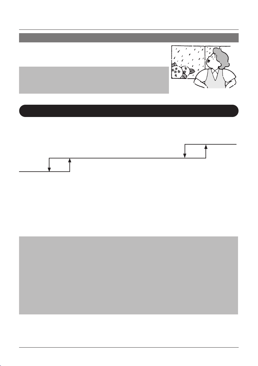
Setback
The Setback function will maintain the room temperature in a specic range when the remote
controller is turned OFF. This is done by temporarily starting the air conditioner that was previously
turned OFF by the user, the schedule function or the OFF timer.
OFF
Cooling Operation
33°C 35°C
Heating
Operation
For example:
[ Setback setpoint temperature: cool 35°C, heat 10°C ]
[ Recovery differential: cool -2°C, heat +2°C ]
• If the room temperature drops below 10°C, heating is started automatically. If after half an hour
• If the room temperature goes above 35°C, cooling is started automatically. If after half an hour
Note
• This function is enabled by default. This function can only be enabled/disabled in the Energy
Saving List (See "Energy Saving Options" on page 38).
• The differential can be adjusted in the Setback Condition menu (See "Setback Condition" on
page 40).
• The setback temperature can be set while the unit is turned off on the Basic Screen or set in the
schedule.
• Setback will turn the unit ON for at least 30 minutes unless the setback temperature setpoint is
changed or the unit is turned ON with the ON/OFF button.
• When setback turns the air conditioner ON while in Auto mode, the remote controller switches to
Cooling or Heating only, depending on what is appropriate, and only the respective setback
temperature setpoint is shown.
BRC1E53 User reference guide
4P419251-1 – 2015.10
10°C 12°C
the temperature increases to 12°C or above, the controller returns to its original state.
the temperature drops to 33°C or below, the controller returns to its original state.
18
Basic Operation Method
Operation Method
Operation Method
Cool
1
Setback
Setback should not be enabled when a centralized controller is connected.
The setback icon " " ashes when the unit is turned ON under
the setback control.
Cool
35°C
The fan speed cannot be changed when setback is active and as
a result, the fan speed is not visible.
Ventilation Operation
(HRV only)
Preparation
• For mechanical protection purposes, turn ON the air conditioner at least 6 hours before
starting the operation of the system.
• Do not turn OFF the air conditioner in-season in order to ensure the smooth starting of the air
conditioner.
• Press the Operation Mode Selector button several times until the ventilation mode is
selected.
• The Ventilation mode is used on Heat Reclaim
1
2
Vent
Ventilation (HRV) units for when cooling or heating
is unnecessary.
• The Ventilation mode can be changed in the Main Menu
(See "Ventilation Mode" on page 37).
Note
Ventilation modes: Auto, Energy Reclaim Ventilation and Bypass
• The Ventilation rate can be changed in the Main Menu
3
User reference guide BRC1E53
4P419251-1 – 2015.10
19
(See "Ventilation Rate" on page 36).
Note
Ventilation rates: Low or High
Basic Operation Method
Cool
Set to
28
°C
Cool
Set to
28
°C
• Press the ON/OFF button.
4
5
The Operation lamp will be lit and the Heat
Reclaim Ventilation unit will start operating.
• When the ON/OFF button is pressed again the
Heat Reclaim Ventilation will stop operating and
the Operation lamp will turn OFF.
Setting the Cooling/Heating Selection Eligibility
(VRV only)
See "Cool/Heat Selection Eligibility" on page 22 for an explanation of the
Setting Changes
1
cooling/heating selection eglibility.
• Press the Operation Mode Selector button on the
remote controller for at least 4 seconds (during
backlight lit).
The remote controller will not display " "
(Changeover under control) if a cooling/heating
selection eligibility is granted to the remote
controller.
• The icon " " (Changeover under control) on each remote
controller of indoor units connected to the same outdoor unit or
BS (Branch Selection) box will start blinking.
• Set a cooling/heating selection eligibility as explained below.
Note
• Ventilation mode changes are possible regardless of the cooling/
heating selection eligibility.
• If a cooling/heating selection eligibility is set in the "cooling/
heating selection remote controller" (
controllers will display " " (Changeover under control). In this
case, the operation mode cannot be changed to respectively
cooling or heating when heating or cooling is set on the "cooling
or heating selection remote controller".
Refer to the Operation Manual provided to the outdoor unit for
the details on the "cooling/heating selection remote controller".
BRC1E53 User reference guide
4P419251-1 – 2015.10
), the other remote
20
Basic Operation Method
Cool
Set to
28
°C
Cool
Set to
28
°C
Operation Method
Selection Settings
2
Cool
Set to
3
The display " " (changeover under control) will blink when the power is
turned ON for the rst time.
• Press the Operation Mode Selector button of the
remote controller for which the selection eligibility
needs to be set.
The cooling/heating selection eligibility will be set
and the icon " " (Changeover under control)
will disappear.
The icon " " (Changeover under control) will
appear on the other remote controllers.
28°C
• Press the Operation Mode Selector button on the
remote controller that has the cooling/heating
selection eligibility (or the remote controller without
the icon " " (Changeover under control))
several times until the desired mode is selected.
The display will change to the "Fan", "Dry", "Auto",
"Cool" or "Heat" icon each time the button is
pressed.
• Simultaneously, the other remote controllers with
no selection right will follow and change the
display automatically.
User reference guide BRC1E53
4P419251-1 – 2015.10
21
Basic Operation Method
Cool/Heat Selection Eligibility
• "Cool", "Heat" or "Auto" mode can only be set by the remote controller for which the cooling/
heating selection eligibility is set.
The remote controller with
the selection eligibility
1.
2.
(without "
(Changeover under
control) displayed)
The remote controller with
the selection eligibility
(without "
(Changeover under
control) displayed)
"
"
Set to "Cool", "Heat",
"Dry" or "Auto" mode.
Set to "Fan" mode.
Other remote controllers
(with "
(Changeover under
control) displayed)
• The air conditioner will go into the
mode set in the remote controller with
the selection eligibility. No other modes
are available.
• The air conditioner, however, can be
switched to Fan Only mode or from
Cool to Dry mode.
Other remote controllers
(with "
(Changeover under
control) displayed)
• The air conditioner cannot be set to
other modes except Fan Only mode.
"
"
BRC1E53 User reference guide
4P419251-1 – 2015.10
22
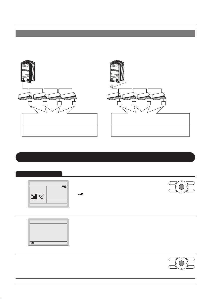
Names and Functions
Precautions for Setting Cooling/Heating Selection Eligibility
• The cooling/heating selection eligibility needs to be set for a single remote controller in the
following case.
(Heat Recovery system)(Heat pump system)
BS (Branch Selection) box:
The BS box is used for cooling or
heating mode selection.
Indoor unitIndoor unit
A number of indoor units are
connected to a single outdoor unit.
Set the cooling/heating/fan selection
eligibility in one of the remote controllers.
Key Lock
Operation Method
Cool
1
2
Buttons have been locked.
Press the menu button for
4 seconds to release.
Set to
Return
Disable the use of all buttons.
• Press the Menu/Enter button for at least
28°C
• "
• All buttons are disabled when the keys are locked.
• When one of the buttons is pressed, the message
• To cancel the key lock, continue pressing the
3
A single BS box is connected to a
number of indoor units.
Set the cooling/heating/auto/fan selection
eligibility in one of the remote controllers.
4 seconds. (During backlight lit)
" will appear.
on the left is displayed.
Menu/Enter button for at least 4 seconds. (During
backlight lit)
User reference guide BRC1E53
4P419251-1 – 2015.10
23
Quick Reference of Main Menu Items
The Main Menu Items Overview.
Note
• The available items may vary with the connected model.
• Only the available items will appear in the menu.
Setting and display items Description
Airow Direction
Individual Air
Direction
(only if the
individual airow
function is
installed)
Quick Start
(SkyAir only)
Ventilation
(HRV only)
Individual Setting Set the airow direction for each of the aps
(1)
Individual Setting
List
Reset All Indivi
Setting
Airow Direction
Range
(1)
Ventilation Rate Set the ventilation rate to "Low" or "High".
Ventilation Mode Set the ventilation mode to "Auto", "Energy
Change the airow direction.
• The airow direction blades can be
automatically operated up and down and left
and right.
• There are ve possible xed airow positions.
• This function is not available on all models.
individually.
• In case of SkyAir, maximum 4 units (unit A, B,
C, D).
• In case of VRV, maximum 16 units (unit 0 till
15).
A table for each unit with the settings for each of
the 4 aps.
Clear all the individual settings.
The auto swing direction is selectable from
three patterns to suit the layout of the room.
Standard , Right blow or Left blow
Quickly brings the room to a comfortable
temperature (unless the system is in dry or
fan operation).
• The maximum quick start operation period is
30 minutes.
Reclaim Ventilation", and "Bypass".
Reference
page
30
31
32
33
34
35
36
37
1) Not supported when SkyAir RR+RQ outdoor units are connected
BRC1E53 User reference guide
4P419251-1 – 2015.10
24

Quick Reference of Main Menu Items
Setting and display items Description
Energy
Saving
Options
Energy Saving
List
(1)
Setpoint Range The setpoint temperature range can be restricted
Setback Condition Set the setback differential temperature after
Sensing
Sensor(Low)(²)(³)
(only if the sensing
sensor is installed)
Sensing
Sensor(Stop)(²)(³)
(only if the sensing
sensor is installed)
Setpoint Auto
Reset
Off Timer The system is turned off automatically after the
Auto Display Off When the system is turned off, it is possible to
Enable or disable the "Energy Saving Options".
for the Cooling and Heating Mode.
which the unit will turn back OFF.
When no people are detected during a set time,
this function will automatically change the air
conditioning target temperature.
If people are detected, it will return to the normal
setpoint temperature.
When no people are detected during a set time,
this function will automatically stop the air
conditioner.
Change the temperature setpoint to a preset
temperature setpoint after running for a set
period of time, even if the temperature setpoint
has been changed.
• Possible to set from 30 to 120 minutes in 30
minute increments.
selected time each time the system is activated.
• Possible to set in 10 minute increments from
30 to 180 minutes.
make the display automatically turn off after a
given time.
• Possible to select "Off", "10min", "30min", or
"60min".
Reference
page
38
39
40
41
42
43
44
44
1)
Setback, Setpoint Range, Setback Condition and Setpoint Auto Reset should not be used when a centralised controller is connected.
2) Not supported when SkyAir RR+RQ outdoor units are connected.
3) This function cannot be used when group control is active.
In case of a simultaneous operation system, the system is controlled by the sensing sensor mounted in the master indoor unit.
User reference guide BRC1E53
4P419251-1 – 2015.10
25

Setting and display items Description
Energy
Saving
Options
Energy
Consumption(²
(1)
An indicative energy consumption until now is
)
displayed. This enables the customer to evaluate
the trend of the energy consumption.
Note
• Function availability depends on the type of
indoor unit
• This function is not available when more than
1 indoor unit is connected to the remote
controller.
• The displayed energy consumption is not the
result of a kWh measurement, but results
from a calculation with running data of the
unit.
• Some factors in this calculation are absolute
values, but other factors merely result from
interpolations with tolerance. This explains
why the readout may deviate from the actual
energy consumption.
Quick Reference of Main Menu Items
Reference
page
45
1)
Setback, Setpoint Range, Setback Condition and Setpoint Auto Reset should not be used when a centralised controller is connected.
2) Not supported when SkyAir RR+RQ outdoor units are connected.
BRC1E53 User reference guide
4P419251-1 – 2015.10
26

Quick Reference of Main Menu Items
Setting and display items Description
(1)
Schedule
Filter Auto Clean
Maintenance Information
Conguration
Current Settings
Clock &
Calendar
Language
1)
The Schedule will not be available when a centralised controller or the BRP7A51 Digital Input Adapter is connected.
2) Not supported when SkyAir RR+RQ outdoor units are connected.
3) This function cannot be used when group control is active.
In case of a simultaneous operation system, the system is controlled by the sensing sensor mounted in the master indoor unit.
User reference guide BRC1E53
4P419251-1 – 2015.10
27
Enable/Disable Enable or disable schedule function.
Select Schedule Select the active schedule number (schedule nr
Holidays Select the days of the week for which the
Settings Select when the operation modes start and/or
Quiet Operation
Mode
Draft Prevention
(only if the sensing
sensor is installed)
Display
Contrast
Adjustment
Date & Time Congure the date and time settings.
12H/24H Clock The time can be displayed in either a 12 hour or
1, 2 or 3).
schedule will be disabled. This function is used
for when the schedule doesn't need to be
active, e.g. like when you are on holiday.
stop for each day of the week. Up to 5 actions
can be set for each day.
Set the time when the lter needs to be
automatically cleaned. For detailed operation
refer to the Operation Manual of the self
cleaning decoration panel.
Display the service contact and model
information.
Schedule the outdoor unit to run more quietly,
e.g. so as not to disturb the neighbours at night.
Note
• Function availability depends on the type of
outdoor unit
(²)
Prevent people from getting affected by the
airow from the indoor unit.
The Draft Prevention function can be enabled
or disabled.
• Display:
Switch between Standard or Detailed display.
• Detailed display settings:
Select if room temperature, outdoor
temperature, system or nothing is displayed.
Adjust the LCD contrast.
Display a list of the current settings of the
available items.
• The default time display is 24H.
• The clock will maintain accurate within
±30 seconds per month.
• If there is a power failure for a period not
exceeding 48 hours, the clock will continue
working with the built-in backup power supply.
24 hour time format.
Choose the language depending on the
language pack installed.
Reference
page
46
47
48
49
51
52
53
53
56
58
58
59
60
61

Menu Items of the Sub Remote
Indoor unit
2 remote controllers
in control
Controller
If 2 remote controllers are in control of a single indoor unit,
the following menu items are not set in the sub remote
controller. Set them in the main remote controller.
• Individual Air Direction
• Energy Saving Options
• Schedule
• Filter Auto Clean
• Setback Temperature Setpoints
• Quiet Operation Mode
• Draft Prevention
Outdoor unit
BRC1E53 User reference guide
4P419251-1 – 2015.10
28

Cool
Set to
28
°C
Operation Method
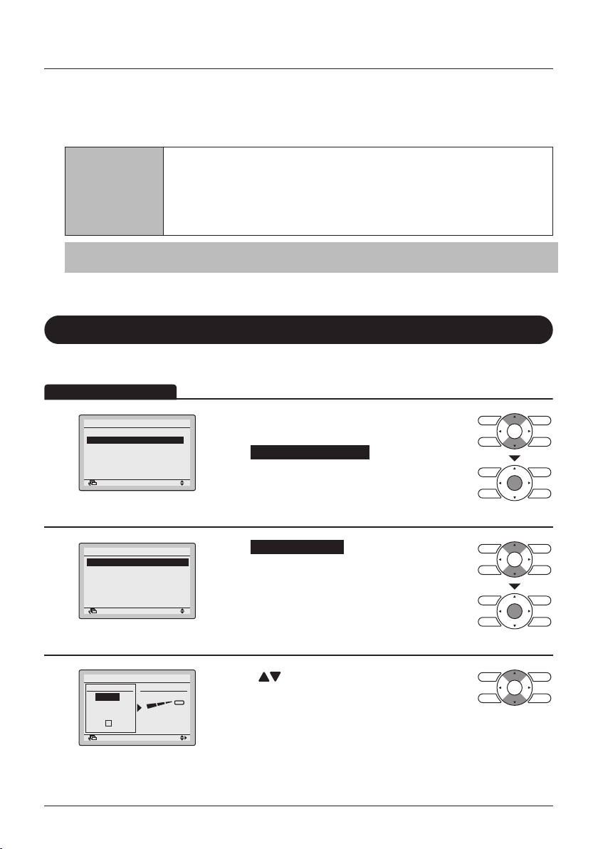
Menu Manipulation
Main Menu
Manipulating the Main Menu
• Press the Menu/Enter button.
1
Basic Screen
• The Main Menu will appear.
1/2
Instructions for manipulating the buttons will
appear.
• Selecting items from the Main Menu.
1. Press the (Up/Down) buttons to select
the desired item.
2. Press the Menu/Enter button to display the
selected settings screen.
2
3
Main Menu
Airflow Direction
Individual Air Direction
Quick Start
Ventilation
Energy Saving Options
Schedule
SettingReturn
Main Menu
• To go back to the Basic Screen from the Main
4
Menu, press the Cancel button.
Caution
• When the Main Menu is visible and a button is not pressed for 5 minutes, the screen will
automatically go back to the Basic Screen.
User reference guide BRC1E53
4P419251-1 – 2015.10
29

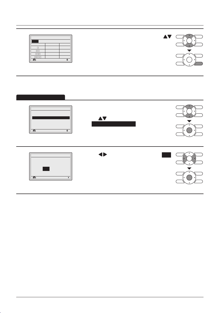
Airow Direction
Operation Method
0
0
2
4
Change the Airow direction
• Display the Main Menu (See "Manipulating the
1/2Main Menu
Main Menu" on page 29)
• Press the
Airow Direction and press the Menu/Enter
button.
1
Airflow Direction
Individual Air Direction
Quick Start
Ventilation
Energy Saving Options
Schedule
SettingReturn
Menu Manipulation
(Up/Down) buttons to select
Airflow Direction
2
Direction1
Swing
Airow direction
setting (up/down)
Airflow Direction
Direction1
Swing
Airow direction
setting (left/right)
Remark: Only visible if
available.
SettingReturn
SettingReturn
Direction2
Swing
Direction2
Swing
• Select the desired airow direction
from No Ind Set , Position 0 , Position 1 ,
Position 2 , Position 3 , Position 4 , Swing
or Auto using the (Up/Down) buttons.
• Select Up/down direction or Left/right direction
using the
(Left/Right) buttons.
• Press the Menu/Enter button to conrm the
settings and to return to the Basic Screen
Note
• The airow directions appear on the screen as follows:
1
2
3
4
Up/down direction
1
3
Left/right direction
• Selecting Swing will cause the airow direction blades to
swing back and forth. When Swing is selected, all airow
directions will be visible at the same time.
• When you select one of the positions 0 to 4, the airow
direction blades stay in a xed position.
0 : Position 0
1 : Position 1
2 : Position 2
3 : Position 3
4 : Position 4
BRC1E53 User reference guide
4P419251-1 – 2015.10
30
Menu Manipulation
Operation Method
Movement of the airow direction blades
When the following operation conditions are active, the airow direction is controlled
automatically. Actual operation may thus be different than what is displayed on the remote
controller.
• Room temperature is higher than the remote controller's set
temperature (in heating mode).
Operation
condition
Note
Heating mode includes automatic operation.
• When Defrost is active (in heating mode).
(The airow is blowing horizontally so that people in the room are not in
direct line of the cold air).
• Under continuous operation with the airow blowing horizontally.
Individual Air Direction
Individual Setting
• Display the Main Menu (See "Manipulating the
Direction
No Ind Set
1/2
Main Menu" on page 29).
• Select Individual Air Direction and press the
Menu/Enter button.
• Select Individual Setting and press the Menu/
Enter button.
• Use the (Up/Down) buttons to select the unit
and outlet mark.
• In case of SkyAir, maximum 4 units (unit
A, B, C, D) can be selected.
In case of VRV, maximum 16 units for each group
(unit 0 till 15) can be selected.
1
2
3
Main Menu
Airflow Direction
Individual Air Direction
Quick Start
Ventilation
Energy Saving Options
Schedule
Individual Air Direction
Individual Setting
Individual Setting List
Reset All Indivi Setting
Airflow Direction Range
Individual Setting
SettingReturn
SettingReturn
Outlet
Unit A
Outletmark
Return Setting
SettingReturn
(Only if the individual airow function is installed)
User reference guide BRC1E53
4P419251-1 – 2015.10
31

Menu Manipulation
Operation Method
Note
In case of four outlets (cassette type), you can control each one of
the four aps individually (the following marks are beside each air
outlet: □, □□, □□□, □□□□).
4
5
Individual Setting
Air Volume
Unit A
Outletmark
Cool
SettingReturn
Set to
Direction
No Ind Set
• Press the (Right) button to select the airow
direction.
• Use the
airow direction to the following:
No Ind Set , Position 0 , Position 1 ,
Position 2 , Position 3 , Position 4 , Swing or
Blocked .
No Ind Set : No Individual Setting.
Blocked : Individual airow is blocked.
• Press the Menu/Enter button to conrm the
settings and to return to the Basic Screen.
• If individual air ow direction is set, then the
individual air ow direction icon is displayed in the
basic screen.
28°C
Basic screen
Individual Setting List
• Display the Individual Air Direction menu (See
"Individual Setting" on page 31).
• Press the
Individual Setting List and press the Menu/Enter
button.
1
Individual Air Direction
Individual Setting
Individual Setting List
Reset All Indivi Setting
Airflow Direction Range
SettingReturn
(Up/Down) buttons to change the
(Up/Down) buttons to select
BRC1E53 User reference guide
4P419251-1 – 2015.10
32
Menu Manipulation
Operation Method
Individual Setting List
Unit A
Outletmark Air direc. Indiv.
2
Return
Position 0 OFF
Position 0 OFF
Position 0 OFF
Position 0 OFF
• A table shows the current settings. Press the
(Up/Down) buttons to go to the next unit.
• Press the Cancel button to return to the previous
menu.
Reset All Individual Settings
• Display the Individual Air Direction menu
(See "Individual Setting" on page 31).
• Press the
select Reset All Indivi Setting and press the Menu/
Enter button.
• Press the (Left/Right) buttons to select Yes .
• Press the Menu/Enter button to conrm the reset
and to return to the Basic Screen.
1
2
Individual Air Direction
Individual Setting
Individual Setting List
Reset All Indivi Setting
Airflow Direction Range
SettingReturn
Reset All Indivi Setting
Clear individual
air flow setting?
NoYes
SettingReturn
(Up/Down) buttons to
User reference guide BRC1E53
4P419251-1 – 2015.10
33
Menu Manipulation
0
2
4
4
0
0
4
Operation Method
Airow Direction Range
(Floor standing type indoor unit only)
• The Airow Direction Range can be selected by the remote controller depending on the installed
location of the air conditioner.
The Airow Direction Range has the following 3 patterns:
Standard Left Blow Right Blow
Fully wide swing Swing on the left side Swing on the right side
• These patterns correspond with the situations as shown below:
Standard Left Blow Right Blow
Fully wide swing Swing on the left side Swing on the right side
1
2
1
Individual Air Direction
Individual Setting
Individual Setting List
Reset All Indivi Setting
Airflow Direction Range
SettingReturn
Airflow Direction Range
Unit select
Unit No.
0
SettingReturn
3
Air range
Standard
1
2
3
• Display the Individual Air Direction menu (See
"Individual Setting" on page 31).
• Press the
Airow Direction Range and press the Menu/
Enter button.
• Press the (Up/Down) buttons to select the
unit number.
Note
• For a simultaneous operation system, individual setup for each
indoor unit is possible by connecting the remote controller to
each unit when installing.
• For remote controllers connected in group, a maximum of 16
units (unit number 0-15) are congurable.
(Up/Down) buttons to select
3
2
1
BRC1E53 User reference guide
4P419251-1 – 2015.10
34

Menu Manipulation
Operation Method
3
Airflow Direction Range
Unit select
Unit No.
Air range
Standard
0
SettingReturn
Quick Start
Quick Start ON
Main Menu
Airflow Direction
Individual Air Direction
Quick Start
1
Ventilation
Energy Saving Options
Schedule
Cool
SettingReturn
Set to
28°C
Quick Start
• Press the (Right) button to select the Air range
setting.
• Select the desired air range from Standard ,
Right blow or Left blow by using the
(Up/Down) buttons.
• Press the Menu/Enter button to conrm the
settings and to return to the Basic Screen.
(SkyAir only)
• While operating in Cooling, Heating or Auto mode,
1/2
display the Main Menu (See "Manipulating the
Main Menu" on page 29).
• Press the
Quick Start and press the Menu/Enter button to
return to the Basic Screen.
• Quick Start is now ON.
• When Quick Start is active, it is not possible to
change the fan speed. The fan speed icons will not
be displayed.
(Up/Down) buttons to select
Quick Start OFF
Main Menu
Airflow Direction
Individual Air Direction
Quick Start
2
Ventilation
Energy Saving Options
Schedule
Cool
SettingReturn
Set to
28°C
User reference guide BRC1E53
4P419251-1 – 2015.10
35
• While Quick Start is active, display the Main Menu
1/2
(See "Manipulating the Main Menu" on
page 29).
• Press the
Quick Start and press the Menu/Enter button to
return to the Basic Screen.
• Quick Start is now OFF.
• The fan speed can be changed again and the fan
speed icons are visible again.
(Up/Down) buttons to select
Quick Start
Operation Method
Menu Manipulation
Quick Start
• The fan speed icons disappear and the fan speed cannot be changed.
• Cannot be set when in Fan Only and Dry mode.
• Quick Start will run for a maximum of 30 minutes before the unit automatically returns to normal
operation.
• Using the Operation Mode Selector button will return the air conditioner to normal operation.
• In heating mode, the fan speed may increase and the temperature may decrease.
Adjust the operation as desired.
Ventilation
The airow rate of the indoor unit is automatically controlled,
increasing the capacity of the outdoor unit and quickly bringing the
room to a comfortable temperature.
(HRV only)
Ventilation Rate
• Display the Main Menu. (See "Manipulating the
1/2
Main Menu" on page 29).
• Press the
select Ventilation and press the Menu/Enter
button (For models with no ventilation
function, Ventilation will not be displayed in the
Main Menu).
2/2
• Press the (Up/Down) buttons to
select Ventilation Rate and press the Menu/Enter
button.
(Up/Down) buttons to
1
2
Main Menu
Airflow Direction
Individual Air Direction
Quick Start
Ventilation
Energy Saving Options
Schedule
Ventilation
Ventilation Rate
Ventilation Mode
SettingReturn
SettingReturn
Ventilation
Ventilation Rate
3
BRC1E53 User reference guide
4P419251-1 – 2015.10
High
SettingReturn
HighLow
• Press the (Up/Down) buttons to change the
setting to Low or High .
• Press the Menu/Enter button to conrm the
settings and to return to the Basic Screen.
* Only modes that can be set are displayed.
36
Menu Manipulation
Operation Method
Ventilation Mode
Ventilation
Ventilation Rate
1
Ventilation Mode
SettingReturn
Ventilation
2
Ventilation mode
Bypass
SettingReturn
3
Cool
Set to
28°C
Ventilation Mode
Auto mode " "
• Display the Ventilation menu.
2/2
(See "Ventilation Rate" on page 36).
• Press the
Ventilation Mode and press the Menu/Enter
button.
2/2
• Press the (Up/Down) buttons to change
the settings as shown below.
* Only modes that can be set are displayed.
• Select the desired ventilation mode.
• Press the Menu/Enter button to conrm the
settings and to return to the Basic Screen.
• The corresponding mode is shown.
Using information from the air conditioner (cooling, heating, fan,
and set temperature) and the Heat Reclaim Ventilation unit
(indoor and outdoor temperatures), the mode is automatically
changed between Energy Reclaim Ventilation and Bypass.
(Up/Down) buttons to select
AutoEnergy Reclaim Vent.Bypass
Energy reclaim
ventilation mode "
Bypass mode " "
User reference guide BRC1E53
4P419251-1 – 2015.10
37
The outdoor air is supplied to the room after passing through a
heat exchanger.
"
The outdoor air is supplied to the room without passing through a
heat exchanger.
Energy Saving Options
Operation Method
Energy Saving List
Some functions should not be enabled when a centralised controller is
connected.
• Display the Main Menu.
1/2
(See "Manipulating the Main Menu" on
page 29).
• Press the
Energy Saving Options and press the Menu/
Enter button.
1
Main Menu
Airflow Direction
Individual Air Direction
Quick Start
Ventilation
Energy Saving Options
Schedule
SettingReturn
Menu Manipulation
(Up/Down) buttons to select
2
3
4
Energy Saving Options
Energy Saving List
Setpoint Range
Setback Condition
Sensing Sensor(Low)
Sensing Sensor(Stop)
Setpoint Auto Reset
Energy Saving List
Energy Saving List
Save the settings?
SettingReturn
Setpoint Range
Setback Condition
Sensing Sensor(Low)
Sensing Sensor(Stop)
Setpoint Auto Reset
Off Timer
SettingReturn
NoYes
SettingReturn
1/2
• Press the (Up/Down) buttons to select
Energy Saving List and press the Menu/Enter
button.
• Press the (Up/Down) buttons to change the
: OFF
: ON
: OFF
: OFF
: ON
: ON
setting to ON or OFF .
• Move the cursor using the
buttons.
(Left/Right)
• Press the Menu/Enter button when all changes
are made. The conrmation screen will appear.
• Press the (Left/Right) buttons to select Yes .
• Press the Menu/Enter button to conrm the
settings and to return to the Basic Screen.
BRC1E53 User reference guide
4P419251-1 – 2015.10
38

Menu Manipulation
Operation Method
Setpoint Range Setting
This function should not be used when a centralised controller is connected.
Energy Saving Options
Energy Saving List
1
Setpoint Range
Setback Condition
Sensing Sensor(Low)
Sensing Sensor(Stop)
Setpoint Auto Reset
Setpoint Range
2
Note
• The default setpoint range restriction is [16°C→32°C]. This setpoint range is the general
setpoint range and is as a result always active regardless of whether Setpoint Range is
enabled or disabled.
• The default setpoint range for setback operation is [33°C→37°C] for cooling and [10°C→15°C]
for heating. This setpoint range cannot be changed.
Setpoint Range
Save the settings?
3
Cool
Heat
SettingReturn
16°C – 32°C
16°C – 32°C
SettingReturn
SettingReturn
1/2
• Display the Energy Saving Options (See "Energy
Saving List" on page 38).
• Press the
Setpoint Range and press the Menu/Enter
button.
• Press the (Up/Down) buttons to change the
cooling or heating temperature setpoint range.
• Move the cursor using the
buttons.
• Press the Menu/Enter button when all changes are
made. The conrmation screen will appear.
• Press the (Left/Right) buttons to select Yes .
• Press the Menu/Enter button to conrm the
NoYes
settings and to return to the Basic Screen.
(Up/Down) buttons to select
(Left/Right)
User reference guide BRC1E53
4P419251-1 – 2015.10
39
Setback Condition
Operation Method
This function should not be used when a centralised controller is connected.
Menu Manipulation
Energy Saving Options
Energy Saving List
1
Setpoint Range
Setback Condition
Sensing Sensor(Low)
Sensing Sensor(Stop)
Setpoint Auto Reset
Setback Condition
Recovery Differential
2
Cool Heat
+2°C
-2°C
Setback Condition
Save the settings?
3
Note
• The default setpoint range restriction is [16°C→32°C]. This setpoint range is the general
setpoint range and is as a result always active regardless of whether Setpoint Range is
enabled or disabled.
• The default setpoint range for setback operation is [33°C→37°C] for cooling and [10°C→15°C]
for heating. This setpoint range cannot be changed.
SettingReturn
SettingReturn
SettingReturn
1/2
• Display the Energy Saving Options (See "Energy
Saving List" on page 38).
• Press the
Setback Condition and press the Menu/Enter
button.
• Press the (Up/Down) buttons to change the
differential for setback operation.
• Move the cursor using the
buttons.
• Press the Menu/Enter button when all changes are
made. The conrmation screen will appear.
• Press the (Left/Right) buttons to select Yes .
• Press the Menu/Enter button to conrm the
NoYes
settings and to return to the Basic Screen.
(Up/Down) buttons to select
(Left/Right)
BRC1E53 User reference guide
4P419251-1 – 2015.10
40

Menu Manipulation
Operation Method
Sensing Sensor(Low)
This function cannot be used when group control is active.
In case of a simultaneous operation system, the system is controlled by the
sensing sensor mounted in the master indoor unit.
1
2
3
Energy Saving Options
Energy Saving List
Setpoint Range
Setback Condition
Sensing Sensor(Low)
Sensing Sensor(Stop)
Setpoint Auto Reset
Sensing Sensor(Low)
Sensing Sensor(Low)
Save the settings?
SettingReturn
Adjust Cool SP:
Adjust Time Cool:
Limit Cool SP:
Adjust Heat SP:
Adjust Time Heat:
Limit Heat SP:
SettingReturn
NoYes
SettingReturn
1/2
• Display the Energy Saving Options (See "Energy
Saving List" on page 38).
• Press the
(Up/Down) buttons to select
Sensing Sensor(Low) and press the Menu/Enter
button.
• Press the (Up/Down) buttons to set the
1.0°C
15 min
35°C
1.0°C
15 min
15°C
energy saving operation when the sensor detects
an absence.
• Move the cursor using the
(Left/Right)
buttons.
• Press the Menu/Enter button when all changes are
made. The conrmation screen will appear.
• Example (settings on the left apply):
If the sensor determines that there is no person in
the room during cooling operation, the cooling
setpoint temperature will automatically increase by
1°C every 15 minutes until the cooling setpoint
temperature is 35°C. On the Basic Screen, the
cooling setpoint temperature will not change.
• Press the (Left/Right) buttons to select Yes .
• Press the Menu/Enter button to conrm the
settings and to return to the Basic Screen.
User reference guide BRC1E53
4P419251-1 – 2015.10
41

Sensing Sensor(Stop)
Operation Method
This function cannot be used when group control is active.
In case of a simultaneous operation system, the system is controlled by the
sensing sensor mounted in the master indoor unit.
Menu Manipulation
1
2
3
Energy Saving Options
Energy Saving List
Setpoint Range
Setback Condition
Sensing Sensor(Low)
Sensing Sensor(Stop)
Setpoint Auto Reset
Sensing Sensor(Stop)
Sensing Sensor(Stop)
Save the settings?
SettingReturn
Unocc Stop On/Off:
Unocc Stop Time:
SettingReturn
NoYes
SettingReturn
OFF
1 hours
1/2
• Display the Energy Saving Options (See "Energy
Saving List" on page 38).
• Press the
Sensing Sensor(Stop) and press the Menu/Enter
button.
• Press the (Up/Down) buttons to set the
energy saving operation when the sensor detects
the absence.
• Move the cursor using the
buttons.
• Press the Menu/Enter button when all changes are
made. The conrmation screen will appear.
• Press the (Left/Right) buttons to select Yes .
• Press the Menu/Enter button to conrm the
settings and to return to the Basic Screen.
(Up/Down) buttons to select
(Left/Right)
BRC1E53 User reference guide
4P419251-1 – 2015.10
42

Menu Manipulation
Operation Method
Setpoint Auto Reset
This function should not be used when a centralised controller is connected.
1
2
3
Energy Saving Options
Energy Saving List
Setpoint Range
Setback Condition
Sensing Sensor(Low)
Sensing Sensor(Stop)
Setpoint Auto Reset
Setpoint Auto Reset
Setpoint Auto Reset
Save the settings?
Cool
Heat
SettingReturn
Set temp.:
Set Time:
Set temp.:
Set Time:
SettingReturn
NoYes
SettingReturn
28 °C
30 min
20°C
30 min
1/2
• Display the Energy Saving Options (See "Energy
Saving List" on page 38).
• Press the
(Up/Down) buttons to select
Setpoint Auto Reset and press the Menu/Enter
button.
2/2
• Press the (Up/Down) buttons to set the
preset temperature and timing for the auto reset of
the setpoint.
• Move the cursor using the
(Left/Right)
buttons.
• Press the Menu/Enter button when all the changes
are made. The conrmation screen will appear.
• Press the (Left/Right) buttons to select Yes .
• Press the Menu/Enter button to conrm the
settings and to return to the Basic Screen.
User reference guide BRC1E53
4P419251-1 – 2015.10
43

OFF Timer
Operation Method
Operation Method
Energy Saving Options
Off Timer
Auto Display Off
1
Energy Consumption
Menu Manipulation
• Display the Energy Saving Options (See "Energy
2/2
Saving List" on page 38).
• Press the
Off Timer and press the Menu/Enter button.
SettingReturn
(Up/Down) buttons to select
Off Timer
After you turn on the unit,
it will automatically turn
2
off in
60
minutes.
SettingReturn
Off Timer
Save the settings?
3
NoYes
SettingReturn
Auto Display Off
Energy Saving Options
Off Timer
1
Auto Display Off
Energy Consumption
SettingReturn
• Use the (Up/Down) buttons to set the time
after which the unit automatically turns off again.
Selections can be made in increments of
10 minutes from 30 to 180 minutes.
Holding down the button causes the number to
change continuously.
The settings conrmation screen will appear when
the Menu/Enter button is pressed.
• Press the (Left/Right) button to select Yes .
• Press the Menu/Enter button to conrm the
settings and to return to the Basic Screen.
2/2
• Display the Energy Saving Options (See "Energy
Saving List" on page 38).
• Press the
Auto Display Off and press the Menu/Enter
button.
(Up/Down) buttons to select
BRC1E53 User reference guide
4P419251-1 – 2015.10
44

Menu Manipulation
Operation Method
2
3
Auto Display Off
Settings
Off
SettingReturn
Auto Display Off
Save the settings?
SettingReturn
NoYes
• Press the (Up/Down) buttons to set the timer.
• Press the Menu/Enter button when the timer is set.
The conrmation screen will appear.
• Press the (Left/Right) buttons to select Yes .
• Press the Menu/Enter button to conrm the
settings and to return to the Basic Screen.
Energy Consumption
1
Energy Saving Options
Off Timer
Auto Display Off
Energy Consumption
SettingReturn
2/2
• Display the Energy Saving Options (See "Energy
Saving List" on page 38).
• Press the
Energy Consumption and press the Menu/Enter
button.
(Up/Down) buttons to select
2
Energy consumption
Today
1
kWh
0 6 12 18 24
Return
Total
10.5 kWh
• Switch screens using the (Left/Right) buttons:
Today > Yesterday > This week (1 week) > Last
week (1 week) > This year (1 year) > Last year.
• Change the range shown in the upper right of the
screen using the
(Up/Down) buttons.
• Press the Cancel button to return to the previous
Energy consumption
This week
10
kWh
S M T W T F S
Return
Energy consumption
This year
1
kWh
0 3 6 9 12
Return
User reference guide BRC1E53
4P419251-1 – 2015.10
45
Total
60.2 kWh
Total
150 kWh
screen.

Schedule
Enable/Disable
Operation Method
Menu Manipulation
The schedule is not visible and disabled when a centralized controller or
the BRP7A51 Digital Input Adapter is connected.
1
2
3
Main Menu
Airflow Direction
Individual Air Direction
Quick Start
Ventilation
Energy Saving Options
Schedule
Schedule
Clock has not been set.
Would you like to set it now?
Date & Time
Year 2016
Month 01
Day 01
Friday
0:00
Schedule
Enable/Disable
Select Schedule
Holidays
Settings
SettingReturn
NoYes
SettingReturn
Return Setting
SettingReturn
• Display the Main Menu.
1/2
(See "Manipulating the Main Menu" on page 29).
• Press the
Schedule and press the Menu/Enter button.
Note
• Before setting the schedule, the clock must be
set.
• If the clock has not been set, a screen like the
one on the left will appear.
• Press the (Left/Right) buttons to select Yes
and press the Menu/Enter button.
• The Date & Time screen will appear.
• Set the current year, month, day and time. (See
"Clock & Calendar" on page 59).
2/2
• Press the (Up/Down) buttons to select
Enable/Disable and press the Menu/Enter button.
(Up/Down) buttons to select
Schedule
Enable/Disable
4
BRC1E53 User reference guide
4P419251-1 – 2015.10
Disable
SettingReturn
• Press the (Up/Down) buttons to select
Enable or Disable .
• The conrmation screen will appear when the
Menu/Enter button is pressed.
Note
The Schedule is enabled. To modify the Selected
schedule number see "Select Schedule" on
page 47.
46
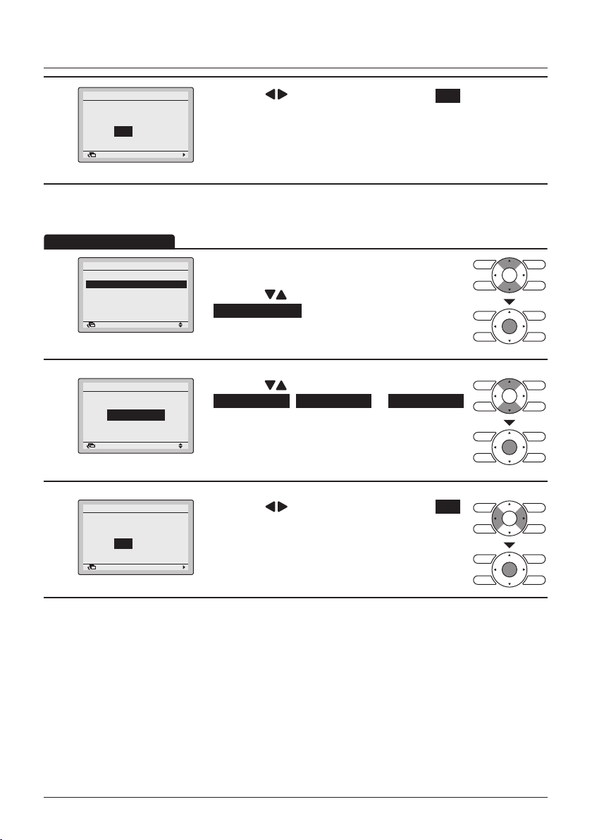
Menu Manipulation
Operation Method
Schedule
Save the settings?
5
NoYes
SettingReturn
Select Schedule
Schedule
Enable/Disable
Select Schedule
1
Holidays
Settings
SettingReturn
Schedule
Select Schedule
2
Schedule nr 1
SettingReturn
• Press the (Left/Right) buttons to select Yes .
• Press the Menu/Enter button to conrm the
settings and to return to the Basic Screen.
It is possible to program up to three different schedules.
• Display the Schedule menu. (See "Enable/
2/2
Disable" on page 46).
• Press the
Select Schedule and press the Menu/Enter
button.
• Press the (Up/Down) buttons to select
Schedule nr 1 , Schedule nr 2 or Schedule nr 3 .
• The conrmation screen will appear when the
Menu/Enter button is pressed.
(Up/Down) buttons to select
Schedule
Save the settings?
3
NoYes
SettingReturn
User reference guide BRC1E53
4P419251-1 – 2015.10
47
• Press the (Left/Right) buttons to select Yes .
• Press the Menu/Enter button to conrm the
settings and to return to the Basic Screen.

Holidays
Operation Method
Schedule
Enable/Disable
1
Select Schedule
Holidays
Settings
Menu Manipulation
The schedule timer will be disabled for days that have been set as a holiday.
• Display the Schedule menu. (See "Enable/
Disable" on page 46).
• Press the
Holidays and press the Menu/Enter button.
SettingReturn
(Up/Down) buttons to select
Schedule
Holidays
2
Multiple selection
SettingReturn
Note
• Multiple days can be selected as holidays.
• To re-enable the schedule timer for the day selected as a holiday, the holiday setting must be
released.
Schedule
Holidays
3
Multiple selection
SettingReturn
Schedule
Save the settings?
4
NoYes
SettingReturn
Schedule nr 1
Time Act Cool Heat
Sun
Hol
SettingReturn
• Press the (Left/Right) buttons to select the
desired day.
SatFriThuWedTueMonSun
• Press the
to set this day as a holiday.
• Press the Menu/Enter button when all changes are
made. The settings conrmation screen will
SatFriThuWedTueMonSun
appear.
• Press the (Left/Right) button to select Yes .
• Press the Menu/Enter button to conrm the
settings and to return to the Basic Screen.
Note
"Hol" will be displayed on the schedule settings
screen for days that have been set as a holiday.
(Up/Down) buttons to display " "
BRC1E53 User reference guide
4P419251-1 – 2015.10
48
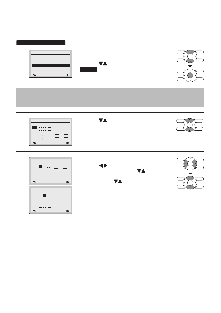
Menu Manipulation
Operation Method
Schedule Settings
After saving a schedule, the schedule is automatically enabled.
Schedule
Enable/Disable
Select Schedule
1
Holidays
Settings
SettingReturn
Note
The Schedule Settings of the selected schedule can be modied. To modify the selected schedule
see "Select Schedule" on page 47.
Schedule nr 1
2
3
Time Act Cool Heat
Mon
SettingReturn
Schedule nr 1
Time Act Cool Heat
Mon
– 6:00
SettingReturn
Schedule nr 1
Time Act Cool Heat
– 6: 00
Mon
• Display the Schedule menu. (See "Enable/
2/2
Disable" on page 46).
• Press the
Settings and press the Menu/Enter button.
• Press the (Up/Down) buttons to select the
day to be set.
• Set the time for the selected day.
• Press the
highlighted item and press the (Up/Down)
buttons to input the desired operation start time.
Each press of the (Up/Down) buttons moves
the numbers by 1 hour or 1 minute.
(Up/Down) buttons to select
(Left/Right) buttons to move the
SettingReturn
User reference guide BRC1E53
4P419251-1 – 2015.10
49
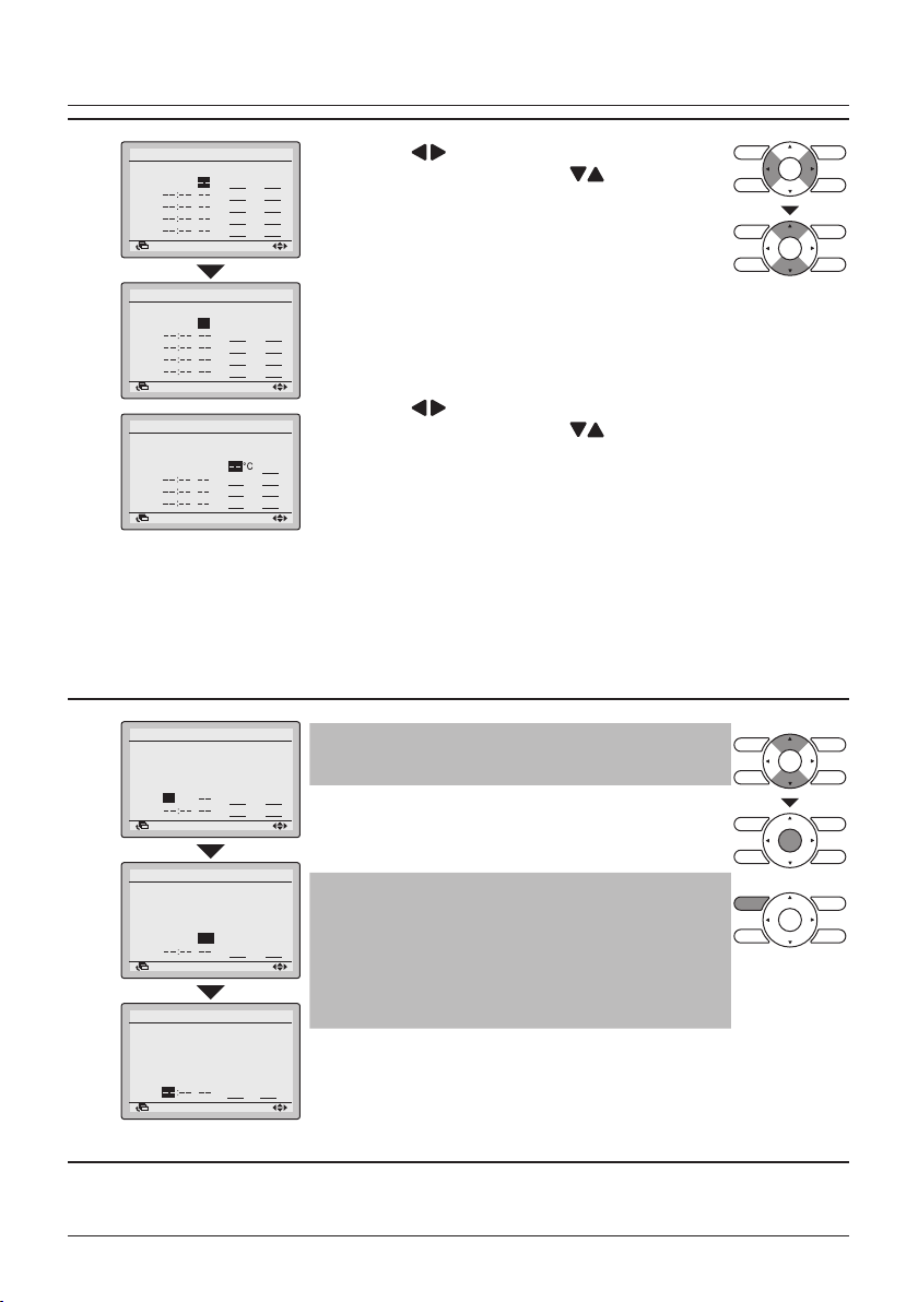
Menu Manipulation
4
5
Schedule nr 1
Time Act Cool Heat
Mon
– 6:00
SettingReturn
Schedule nr 1
Time Act Cool Heat
Mon
– 6:00
ON 32°C
SettingReturn
Schedule nr 1
Time Act Cool Heat
Mon
– 6:00
ON 24°C
– 8:00
OFF
SettingReturn
Schedule nr 1
Time Act Cool Heat
Mon
– 6:00
ON
24°C
– 8:00
OFF
29°C
17:30
ON
24°C
22:00
SettingReturn
• Press the (Left/Right) buttons to move the
highlighted item and press the (Up/Down)
buttons to congure ON/OFF/-- settings.
"Act"-column:
ON : The temperature setpoints can be
congured.
OFF : The setback temperature setpoints can be
16°C
congured.
– – : The temperature and setback temperature
setpoints will be disabled.
• Press the
(Left/Right) buttons to move the
highlighted item and press the (Up/Down)
21°C
buttons to input the cooling and heating
temperature setpoints for both ON and OFF
(Setback) operation.
"Cool" and "Heat" column:
"__": Indicates that the temperature and setback
temperature setpoint for this time period is
not specied. The last active setpoint will be
utilized.
"– –": Indicates that the setback function is
disabled for this time period.
Note
21°C
A maximum of 5 actions per day can be set.
10°C
21°C
• Press the Menu/Enter button when all changes are
made. The conrmation screen will appear.
Schedule nr 1
Time Act Cool Heat
Mon
– 6:00
ON 24°C
– 8:00
OFF
29°C
17:30
ON 24°C
22:00
OFF
28°C
SettingReturn
Schedule nr 1
Time Act Cool Heat
Tue
– 6:00
ON
24°C
– 8:00
OFF
29°C
17:30
ON
24°C
22:00
OFF
28°C
SettingReturn
Note
21°C
10°C
To copy the settings from the previous day, press
21°C
the Operation Mode Selector button.
17°C
Example: To copy the contents of Monday to
Tuesday, select Tuesday and press the Operation
Mode Selector button.
21°C
10°C
21°C
17°C
BRC1E53 User reference guide
4P419251-1 – 2015.10
50
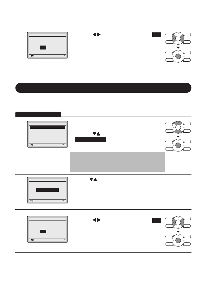
Menu Manipulation
NoYes
Save the settings?
Filter Auto Clean
SettingReturn
Operation Method
Schedule
Save the settings?
6
NoYes
SettingReturn
Filter Auto Clean
• For detailed operation refer to the Operation Manual of the self cleaning decoration panel.
• Press the (Left/Right) buttons to select Yes .
• Press the Menu/Enter button to conrm the
settings and to return to the Basic Screen.
(Only when the self cleaning decoration panel is installed)
Filter Auto Clean Time
• Display the Main Menu. (See "Manipulating the
2/2
Main Menu" on page 29).
• Press the
Filter Auto Clean and press the Menu/Enter
button.
Note
When lter Auto Clean has been disabled, the
message "Auto Filter Clean is disabled" is shown.
(Up/Down) buttons to select
1
Main Menu
Filter Auto Clean
Maintenance Information
Configuration
Current Settings
Clock & Calendar
Language
SettingReturn
Filter Auto Clean
Filter Auto Clean
2
0:00 - 3:00
SettingReturn
3
User reference guide BRC1E53
4P419251-1 – 2015.10
51
• Use the (Up/Down) buttons to set the time
when the auto cleaning function of the lter needs
to be executed.
• The conrmation screen will appear when the
Menu/Enter button is pressed.
• Press the (Left/Right) buttons to select Yes .
• Press the Menu/Enter button to conrm the
settings and to return to the Basic Screen.

Maintenance Information
Operation Method
Display the Maintenance Information
• Display the Main Menu. (See "Manipulating the
2/2Main Menu
Main Menu" on page 29).
• Press the
(Up/Down) buttons to select
Maintenance Information and press the Menu/
Enter button.
1
Filter Auto Clean
Maintenance Information
Configuration
Current Settings
Clock & Calendar
Language
SettingReturn
Menu Manipulation
2
Maintenance Information
Contact Info
0123–4567–8900
Return
–––
–––
/000
/000
Indoor Model
Outdoor Model
• The phone number for the contact address will
R32
appear at the top of the screen.
(If you have not yet registered your product, it will
not appear).
• The model information of the indoor and outdoor
units of your product will appear on the bottom of
the screen.
(For some models the product code may appear).
• Press the Cancel button to return to the previous
screen.
Note
• The model name will not appear if you have had
the circuit board replaced.
• In case of an indoor unit or outdoor unit error, an
error code is displayed and the operation lamp
starts blinking.
If the operation lamp is not blinking, the unit is
working properly.
• The error code record will disappear if you press
the ON/OFF button for more than 4 seconds.
BRC1E53 User reference guide
4P419251-1 – 2015.10
52
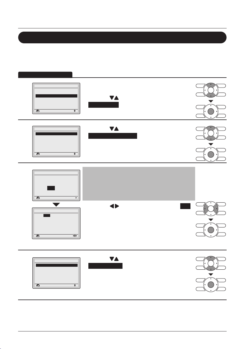
Menu Manipulation
Operation Method
Conguration
Quiet Operation Mode
Enable/Disable
1
2
3
Main Menu
Filter Auto Clean
Maintenance Information
Configuration
Current Settings
Clock & Calendar
Language
SettingReturn
Configuration
Quiet Operation Mode
Draft Prevention
Display
Contrast Adjustment
SettingReturn
Quiet Operation Mode
Clock has not been set.
Would you like to set it now?
NoYes
SettingReturn
Date & Time
Year 2016
Month 01
Day 01
Friday
0:00
Return Setting
• Display the Main Menu.
2/2
(See page 29).
• Press the
Conguration and press the Menu/Enter button.
• Press the (Up/Down) buttons to select
Quiet Operation Mode and press the Menu/Enter
button.
Note
• Before being able to make changes to the Quiet
Operation Mode settings, the clock must be set.
• If the clock has not been set, a screen like the
one on the left will appear.
• Press the (Left/Right) buttons to select Yes
and press the Menu/Enter button.
• The Date & Time screen will appear.
• Set the current year, month, day and time. (See
"Clock & Calendar" on page 59).
(Up/Down) buttons to select
Quiet Operation Mode
Enable/Disable
4
Settings
SettingReturn
User reference guide BRC1E53
4P419251-1 – 2015.10
53
• Press the (Up/Down) buttons to select
2/2
Enable/Disable an press the the Menu/Enter
button.
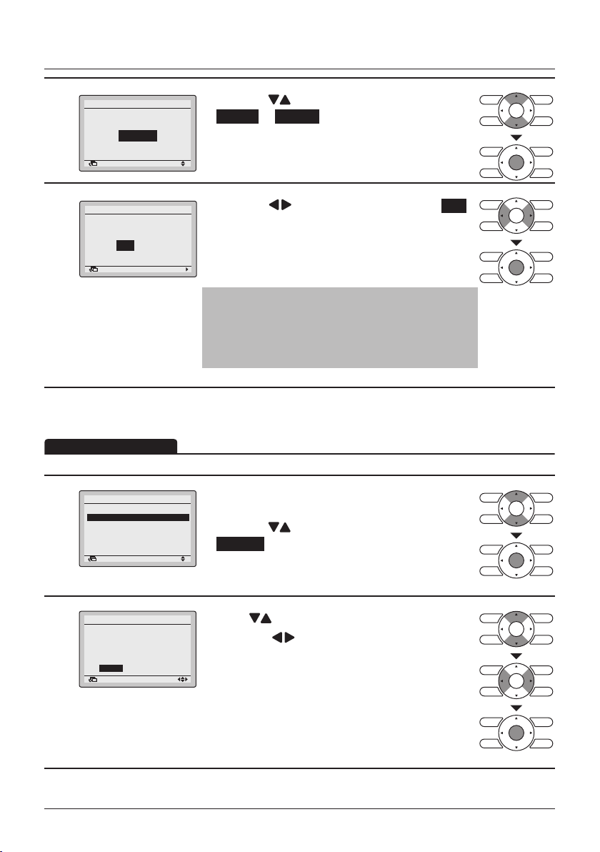
Menu Manipulation
Operation Method
5
6
Quiet Operation Mode
Enable/Disable
Disable
SettingReturn
Quiet Operation Mode
Save the settings?
NoYes
SettingReturn
• Press the (Up/Down) buttons to select
Enable or Disable .
• The conrmation screen will appear when the
Menu/Enter button is pressed.
• Press the (Left/Right) buttons to select Yes .
• Press the Menu/Enter button to conrm the
settings and to return to the Basic Screen.
Note
To set the time for Quiet Operation Mode, see "Quiet
Operation Mode Settings" on page 54.
Quiet Operation Mode Settings
After saving changes to the settings, Quiet Operation Mode is automatically enabled
• Display the Quiet Operation Mode menu.
2/2
(See page 53).
• Press the
Settings and press the Menu/Enter button.
(Up/Down) buttons to select
1
Quiet Operation Mode
Enable/Disable
Settings
SettingReturn
Quiet Operation Mode
Configuration
2
The system will operate
in Quiet Operation Mode
from
to
22:00
8:00
SettingReturn
BRC1E53 User reference guide
4P419251-1 – 2015.10
• Press (Up/Down) buttons to set the time.
• Press the
highlighted item.
• Press the Menu/Enter button when all the changes
are made. The conrmation screen will appear.
(Left/Right) buttons to move the
54
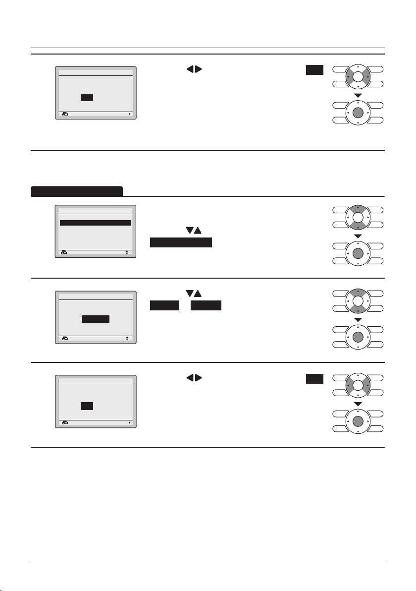
Menu Manipulation
Operation Method
Quiet Operation Mode
Save the settings?
3
NoYes
SettingReturn
Draft Prevention
Configuration
Quiet Operation Mode
1
Draft Prevention
Display
Contrast Adjustment
SettingReturn
Draft Prevention
Enable/Disable
2
Disable
SettingReturn
• Press the (Left/Right) buttons to select Yes .
• Press the Menu/Enter button to conrm the
settings and to return to the Basic Screen.
• Display the Conguration menu.
(See page 53).
• Press the
Draft Prevention and press the Menu/Enter
button.
• Press the (Up/Down) buttons to select
Enable or Disable .
• The conrmation screen will appear when the
Menu/Enter button is pressed.
(Up/Down) buttons to select
Draft Prevention
Save the settings?
3
NoYes
SettingReturn
User reference guide BRC1E53
4P419251-1 – 2015.10
55
• Press the (Left/Right) buttons to select Yes .
• Press the Menu/Enter button to conrm the
settings and to return to the Basic Screen.

Display
Operation Method
Display Mode
Menu Manipulation
Configuration
Quiet Operation Mode
1
Draft Prevention
Display
Contrast Adjustment
SettingReturn
Display
Display Mode Standard
2
Display Item None
SettingReturn
Display
Display Mode
3
Note
To select which item is displayed in the detailed display selection area, refer to "Detailed Item" on
page 57.
Standard
SettingReturn
• Display the Conguration menu. (See "Draft
Prevention" on page 55).
• Press the
Display and press the Menu/Enter button.
• Press the (Up/Down) buttons to select
Display Mode and press the Menu/Enter button.
• Press the (Up/Down) buttons to select
Standard or Detailed .
• Press the Menu/Enter button to conrm the
settings and to return to the Basic Screen.
(Up/Down) buttons to select
BRC1E53 User reference guide
4P419251-1 – 2015.10
56

Menu Manipulation
*
*
Outside Air Temp
None
Operation Method
Detailed Item
Display
Display Mode Standard
Display Item None
1
Display
Display Item
2
SettingReturn
None
SettingReturn
• Display the Display menu. (See "Display Mode" on
page 56).
• Press the
Display Item and press the Menu/Enter button.
• Press the (Up/Down) buttons to display the
following.
System
* Some models may not display these items even if they are
selected.
• Be sure to read the following regarding the display of the room
and outdoor temperature.
Room Temp
– The temperature near the remote controller.
– The temperature that is detected may be affected by the
location of the unit.
– It is possible to switch between the remote controller or the
indoor unit for the used temperature sensor. For detailed
information, refer to the Field Settings in the installer
reference guide.
Outside Air Temp
– The temperature detected near the outdoor unit.
– The temperature that is detected may be affected by factors
such as the location of the unit (e.g if it is in direct sunlight)
and unit operation during defrosting.
(Up/Down) buttons to select
Room Temp
• Press the Menu/Enter button to conrm the
settings and to return to the Basic Screen.
User reference guide BRC1E53
4P419251-1 – 2015.10
57

Contrast Adjustment
Operation Method
Operation Method
Menu Manipulation
• Display the Conguration menu. (See "Draft
Prevention" on page 55).
• Press the
(Up/Down) buttons to select
1
Configuration
Quiet Operation Mode
Draft Prevention
Display
Contrast Adjustment
Contrast adjustment and press the Menu/Enter
2
SettingReturn
Contrast Adjustment
Dark
Light
SettingReturn
button.
• Press the (Up/Down) buttons until you reach
the desired contrast.
• Press the Menu/Enter button to conrm the setting
and to return to the Basic Screen.
Current Settings
Overview of the Current Settings
• Display the Main Menu. (See "Manipulating the
2/2
Main Menu" on page 29).
• Press the
(Up/Down) buttons to select
Current Settings and press the Menu/Enter
button.
1
Main Menu
Filter Auto Clean
Maintenance Information
Configuration
Current Settings
Clock & Calendar
Language
SettingReturn
• A list showing the status of the current settings will
1/2
Low
Auto
Disable
OFF
Standard
None
appear.
• Press the
(Left/Right) buttons to go to the
next screen.
• Press the Cancel button to return to the Main
2
Current Settings
Ventilation Rate
Ventilation Mode
Schedule
Quick Start
Display Mode
Display Item
Return
Menu.
Display items
Ventilation Rate Schedule Display Mode Filter Auto Clean
Ventilation Mode Quick Start Display Item
* Display items may differ depending on the model. Only the items that can be set are displayed.
BRC1E53 User reference guide
4P419251-1 – 2015.10
58

Menu Manipulation
Operation Method
Clock & Calendar
Date & Time
2/2Main Menu
1
Filter Auto Clean
Maintenance Information
Configuration
Current Settings
Clock & Calendar
Language
SettingReturn
• Display the Main Menu. (See "Manipulating the
Main Menu" on page 29).
• Press the
Clock & Calendar and press the Menu/Enter
button.
(Up/Down) buttons to select
2
3
4
Clock & Calendar
Date & Time
12H/24H Clock
SettingReturn
Date & Time
Year 2016
Month 01
Day 01
Friday
0:00
Return Setting
• Press the (Up/Down) buttons to select
Date & Time and press the Menu/Enter button.
• Use the (Up/Down) buttons to change the
date and time.
• Move the cursor using the
buttons.
• Press the Menu/Enter button when all changes are
made. The conrmation screen will appear.
(Left/Right)
Caution
• By default the Daylight Saving Time (DST) is active. The following rules
apply:
– Start: Last Sunday of March 02:00
– End: Last Sunday of October 03:00
• Please consult your Daikin dealer if the DST settings needs to be
changed.
Note
The day of the week is set automatically.
Date & Time
Save the settings?
SettingReturn
NoYes
• Press the (Left/Right) button to select Yes .
• Press the Menu/Enter button to conrm the
settings and to return to the Basic Screen.
User reference guide BRC1E53
4P419251-1 – 2015.10
59

12H/24H CLOCK
Operation Method
Menu Manipulation
1
2
3
Clock & Calendar
Date & Time
12H/24H Clock
SettingReturn
12H/24H Clock
24H
SettingReturn
12H/24H Clock
Save the settings?
SettingReturn
• Display the Clock & Calendar menu. (See "Date &
Time" on page 59).
• Press the
12H/24H Clock and press the Menu/Enter button.
• Press the (Up/Down) buttons to select 12H
or 24H .
• The conrmation screen will appear when the
Menu/Enter button is pressed.
Note
By default, the time display is set to the 24H format.
• Press the (Left/Right) buttons to select Yes .
• Press the Menu/Enter button to conrm the setting
NoYes
and to return to the Main Menu.
(Up/Down) buttons to select
BRC1E53 User reference guide
4P419251-1 – 2015.10
60

Menu Manipulation
Operation Method
Language
Select the Language
• Display the Main Menu. (See "Manipulating the
2/2Main Menu
• Press the
1
Filter Auto Clean
Maintenance Information
Configuration
Current Settings
Clock & Calendar
Language
SettingReturn
Main Menu" on page 29).
(Up/Down) buttons to select
Language and press the Menu/Enter button.
Language
2
English
SettingReturn
Note
The visible languages are depending on the installed language pack.
For detailed information on the available languages and on how to change the language pack,
refer to the installer reference guide.
• Press the (Up/Down) buttons to select the
prefered language.
• Press the Menu/Enter button to conrm the
settings and to return to the Basic Screen.
User reference guide BRC1E53
4P419251-1 – 2015.10
61

Reset Filter Indication
Operation Method
• When the time to clean the lter and/or element has come, one of
1
Cool
Time to clean filter
Set to
28°C
the following messages/icons will appear at the bottom of the
Basic Screen:
– "Time to clean lter" / " "
– "Time to clean lter & element" / " " + " "
– "Time to clean element" / " "
• Wash, clean or replace the lter or element.
For details, refer to the Operation Manual of the indoor unit.
Maintenance
2
3
Main Menu
Reset Filter Indicator
Airflow Direction
Individual Air Direction
Quick Start
Ventilation
Energy Saving Options
SettingReturn
Cool
Set to
28°C
Dust Collection Method
SettingReturn
Dust Collection Method
Dust Collected?
NoYes
SettingReturn
• To reset the lter sign when the lter or element is
1/3
washed, cleaned or replaced , display the Main
Menu (See "Manipulating the Main Menu" on
page 29 ).
• Press the
Reset Filter Indicator .
• Press the Menu/Enter button to reset the lter
indicator and to return to the Basic Screen.
• The icon(s) shown in Step 1 will disappear from
the Basic Screen when the lter sign is reset.
• When an indoor unit with a self cleaning casette is
installed, there will rst be prompted to collect the
dust from the dustbin in the unit.
• Press the Menu/Enter button to conrm and the
conrmation screen will appear.
• Press the
Press the Menu/Enter button to conrm and to
return to the Basic Screen.
• Continue the normal procedure to reset the lter
indicator.
(Up/Down) buttons to select
(Left/Right) buttons to select Yes .
BRC1E53 User reference guide
4P419251-1 – 2015.10
62

Maintenance
Caution
• Do not wash the remote
controller.
Doing so may cause electric
leakage and result in electric
shocks or re.
• Be sure to stop the operation of
the air conditioner and turn off
the power supply breaker when
performing maintenance
activities.
Failure to do so may result in
electric shocks or injury.
Maintenance of Unit and the LCD display
Note:
• Wipe the LCD display and the rest of the surface of the remote controller with a dry cloth when
they become dirty.
• If the dirt on the surface cannot be removed, soak the cloth in neutral detergent diluted with
water, squeeze the cloth tightly, and clean the surface. Wipe the surface with a dry cloth
afterwards.
• Do not use any paint thinner, organic solvent or strong acid.
Warning
Do not use ammable materials (e.g., hairspray or insecticide) near the air
conditioner.
Do not clean the product with organic solvents such as benzine or paint
thinner.
The use of organic solvents may cause crack damage to the product, electric shocks
or re.
User reference guide BRC1E53
4P419251-1 – 2015.10
63

Operation
Operation Method
Reference Information
Error Code Display
Contact your Daikin dealer in the following cases
Warning
When the air conditioner is malfunctioning (e.g., giving off a burning odor), stop
the air conditioner and turn off the power.
Continued operation under such circumstances may result in failure, electric shocks
or re. Contact your Daikin dealer.
1
2
Cool
Error : Push Menu Button
Error Code:A1
Contact Info
0123–4567–8900
Indoor Model
Outdoor Model
Return
Set to
28°C
–––
/000
–––
/000
• If an error occurs, the error icon in the Basic
Screen and the operation lamp will blink.
• If a warning occurs, only the error icon will blink
and the operation lamp will not blink.
• To display the error code and contact information,
press the Menu/Enter button.
• The error code blinks and the contact address and
model name will appear.
• Notify your Daikin dealer of the Error code and
Model name.
lamp
BRC1E53 User reference guide
4P419251-1 – 2015.10
64
Reference Information
After-sale Service
Warning
• Do not disassemble, modify or
repair the unit.
Doing so may result in electric
shocks or re.
Consult your Daikin dealer.
Advise the repairer of the following items
• Model name
• Date of installation
• Failure conditions: As precise as possible.
• Your address, name and telephone number
Relocation
The relocation of the remote controller requires special equipment. Consult your Daikin dealer.
Actual expenses required for the relocation of the remote controller will be charged.
• Do not relocate or reinstall the
remote controller by yourself.
Improper installation may result in
electric shocks or re.
Consult your Daikin dealer.
Repairs after Warranty Period
Consult your Daikin dealer.
Fair-paying services may be possible at the request of the customer.
Inquiry about After-sale Service
Contact your Daikin dealer.
User reference guide BRC1E53
4P419251-1 – 2015.10
65


4P419251-1
2015.10
Copyright 2015 Daikin
 Loading...