

Page 1
DMCI
XF105System and component information
Page 2

Page 3

©200528 DAF Trucks N.V., Eindhoven,
The Netherlands.
In the interest of continuing product development,
DAF reserves the right to change specifications
or products at any time without prior notice.
No part of this publication may be reproduced
and/or published by printing, by photocopying, on
microfilm or in any way whatsoever without the
prior consent in writing of DAF Trucks N.V.
©
200528 DW332094
Page 4

Page 5

XF105 series
STRUCTURE
Structure
TECHNICAL DATA
0
DMCI ENGINE MANAGEMENT SYSTEM
1
©
200528
Page 6

Page 7

TECHNICAL DATA
XF105 series
Contents
CONTENTS
Page Date
1. DMCI ENGINE MANAGEMENT SYSTEM . . . . . . . . . . . . . . . . . . . . . . . . . . . . . 1-1 . . . . . 200528
1.1 Power supply and earth of DMCI electronic unit . . . . . . . . . . . . . . . . . . . . 1-1 . . . . . 200528
1.2 DMCI electronic unit CAN connections . . . . . . . . . . . . . . . . . . . . . . . . . . . 1-2 . . . . . 200528
1.3 Status signals DMCI electronic unit . . . . . . . . . . . . . . . . . . . . . . . . . . . . . . 1-3 . . . . . 200528
1.4 Accelerator pedal sensor . . . . . . . . . . . . . . . . . . . . . . . . . . . . . . . . . . . . . . 1-4 . . . . . 200528
1.5 Coolant temperature sensor . . . . . . . . . . . . . . . . . . . . . . . . . . . . . . . . . . . 1-6 . . . . . 200528
1.6 2
1.7 Inlet air boost pressure and temperature sensor. . . . . . . . . . . . . . . . . . . . 1-10 . . . . 200528
1.8 Fuel pressure and temperature sensor . . . . . . . . . . . . . . . . . . . . . . . . . . . 1-13 . . . . 200528
1.9 Engine oil pressure and temperature sensor. . . . . . . . . . . . . . . . . . . . . . . 1-16 . . . . 200528
1.10 Crankshaft sensor . . . . . . . . . . . . . . . . . . . . . . . . . . . . . . . . . . . . . . . . . . . 1-19 . . . . 200528
1.11 Camshaft sensor . . . . . . . . . . . . . . . . . . . . . . . . . . . . . . . . . . . . . . . . . . . . 1-21 . . . . 200528
1.12 Engine oil level sensor. . . . . . . . . . . . . . . . . . . . . . . . . . . . . . . . . . . . . . . . 1-23 . . . . 200528
1.13 Switches (manual gearbox) . . . . . . . . . . . . . . . . . . . . . . . . . . . . . . . . . . . . 1-25 . . . . 200528
1.14 Switches (AS Tronic) . . . . . . . . . . . . . . . . . . . . . . . . . . . . . . . . . . . . . . . . . 1-26 . . . . 200528
1.15 Extra bulkhead lead-through functions . . . . . . . . . . . . . . . . . . . . . . . . . . . 1-27 . . . . 200528
1.16 Red warning . . . . . . . . . . . . . . . . . . . . . . . . . . . . . . . . . . . . . . . . . . . . . . . 1-28 . . . . 200528
1.17 Starter motor . . . . . . . . . . . . . . . . . . . . . . . . . . . . . . . . . . . . . . . . . . . . . . . 1-29 . . . . 200528
1.18 Glow components . . . . . . . . . . . . . . . . . . . . . . . . . . . . . . . . . . . . . . . . . . . 1-30 . . . . 200528
1.19 Waste gate valve . . . . . . . . . . . . . . . . . . . . . . . . . . . . . . . . . . . . . . . . . . . . 1-31 . . . . 200528
1.20 Exhaust brake valve . . . . . . . . . . . . . . . . . . . . . . . . . . . . . . . . . . . . . . . . . 1-33 . . . . 200528
1.21 DEB solenoid valve . . . . . . . . . . . . . . . . . . . . . . . . . . . . . . . . . . . . . . . . . . 1-34 . . . . 200528
1.22 Pump unit . . . . . . . . . . . . . . . . . . . . . . . . . . . . . . . . . . . . . . . . . . . . . . . . . 1-36 . . . . 200528
1.23 Injector. . . . . . . . . . . . . . . . . . . . . . . . . . . . . . . . . . . . . . . . . . . . . . . . . . . . 1-38 . . . . 200528
1.24 Electronically controlled fan clutch . . . . . . . . . . . . . . . . . . . . . . . . . . . . . . 1-40 . . . . 200528
nd
coolant temperature sensor. . . . . . . . . . . . . . . . . . . . . . . . . . . . . . . . . 1-8 . . . . . 200528
0
©
200528 1
Page 8

0
TECHNICAL DATA
Contents XF105 series
2
©
200528
Page 9
TECHNICAL DATA
XF105 series
DMCI engine management system
1. DMCI ENGINE MANAGEMENT SYSTEM
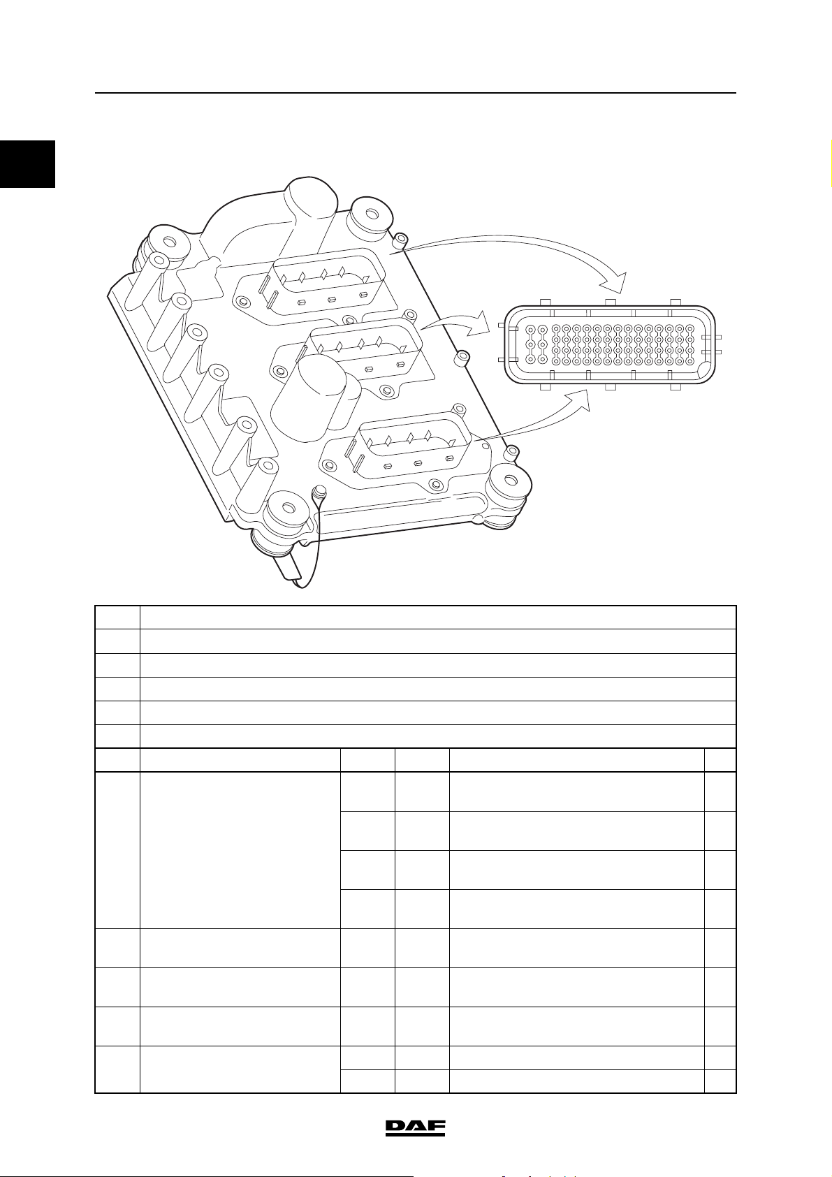
1.1 POWER SUPPLY AND EARTH OF DMCI ELECTRONIC UNIT
A
41
45
49
53
57
60 62
C
B
0
21
25
29
33
37
1 4591317
i400726
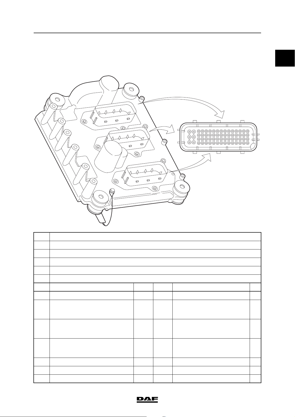
A Electronic unit connection point
B Description of connection point
C Reading at connection point (Ubat = battery voltage)
D Measuring unit
E Explanatory notes (if applicable)
F Additional information available in Technical Data at "X" mark
AB C D E F
B44 Power supply after ignition (G426) Ubat V DC Ignition on
B57 Earth < 0.5 VDC Voltage loss measurement with
as many consumers as possible
switched on.
B58 Earth < 0.5 VDC Voltage loss measurement with
as many consumers as possible
switched on.
B59 Earth < 0.5 VDC Voltage loss measurement with
as many consumers as possible
switched on.
B60 Power supply before ignition (G126) Ubat VDC
B61 Power supply before ignition (G126) Ubat VDC
B62 Power supply before ignition (G126) Ubat VDC
©
200528 1-1
Page 10
0
TECHNICAL DATA
DMCI engine management system XF105 series
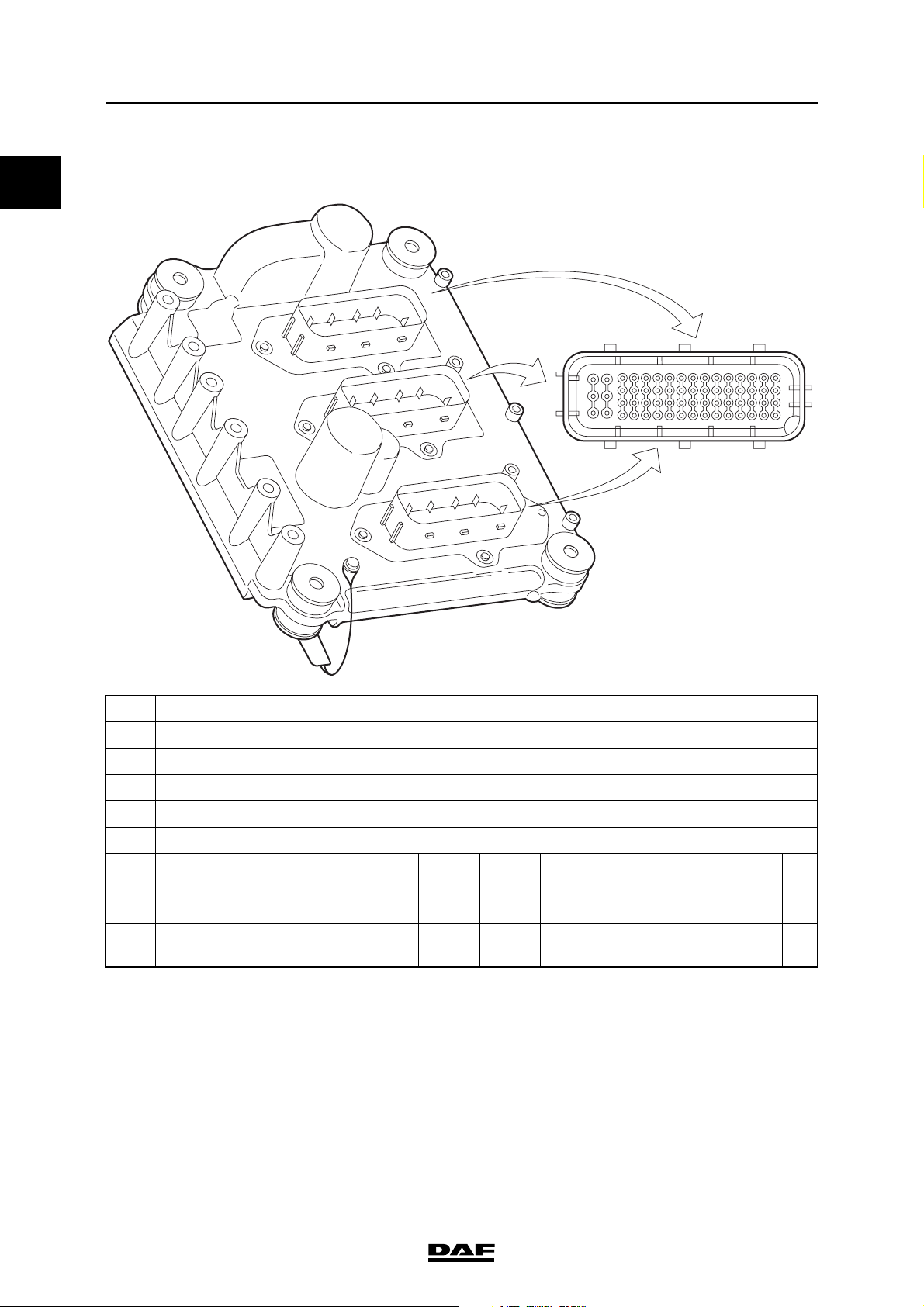
1.2 DMCI ELECTRONIC UNIT CAN CONNECTIONS
A
C
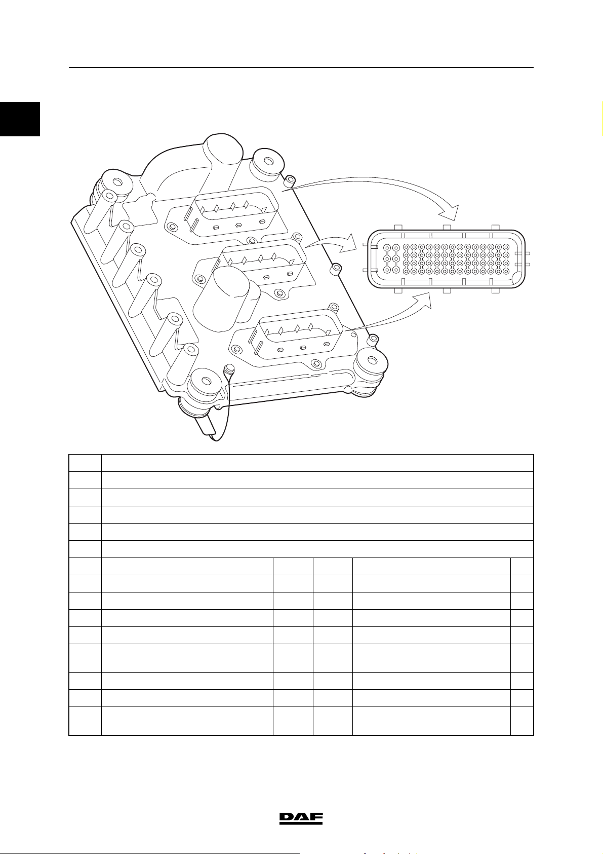
A Electronic unit connection point
B Description of connection point
C Reading at connection point (Ubat = battery voltage)
D Measuring unit
B
21
25
29
33
37
41
45
49
53
57
60 62
1 4591317
i400726
E Explanatory notes (if applicable)
F Additional information available in Technical Data at "X" mark
AB C D E F
B27 V-CAN1-H According to ISO 11898
B35 V-CAN1-L According to ISO 11898
B42 V-CAN1 through connection According to ISO 11898
B45 V-CAN2-H According to ISO 11898 X
B46 V-CAN1 terminating resistance
According to ISO 11898 X
through connection
B50 V-CAN1 through connection According to ISO 11898 X
B53 V-CAN2-L According to ISO 11898 X
B54 V-CAN1 terminating resistance
According to ISO 11898
through connection
V-CAN1 terminating resistance ≥120
V-CAN2 terminating resistance ≥120
(1) Check the resistance by measuring at connection points B46 and B50 of the electronic unit.
(2) Check the resistance by measuring at connection points B45 and B53 of the electronic unit.
1-2
(1)
(2)
©
200528
Page 11
TECHNICAL DATA
XF105 series
1.3 STATUS SIGNALS DMCI ELECTRONIC UNIT
A
C
B
DMCI engine management system
21
25
29
33
37
41
45
49
53
57
60 62
1 4591317
0
i400726
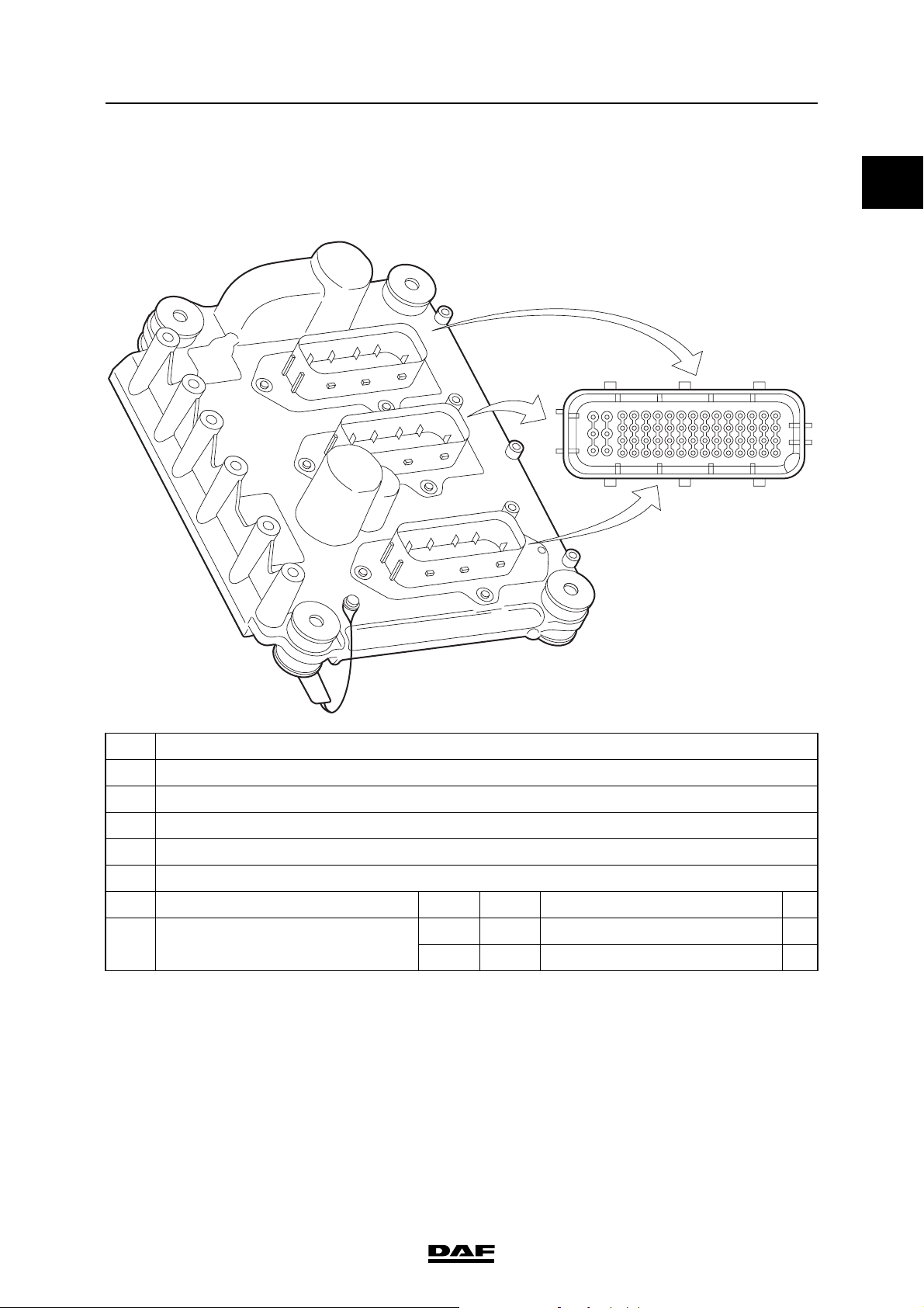
A Electronic unit connection point
B Description of connection point
C Reading at connection point (Ubat = battery voltage)
D Measuring unit
E Explanatory notes (if applicable)
F Additional information available in Technical Data at "X" mark
AB C D E F
B51 Input signal, service brake (G469) Ubat V DC Brake pedal not operated
0 V DC Brake pedal operated
©
200528 1-3
Page 12
0
TECHNICAL DATA
DMCI engine management system XF105 series
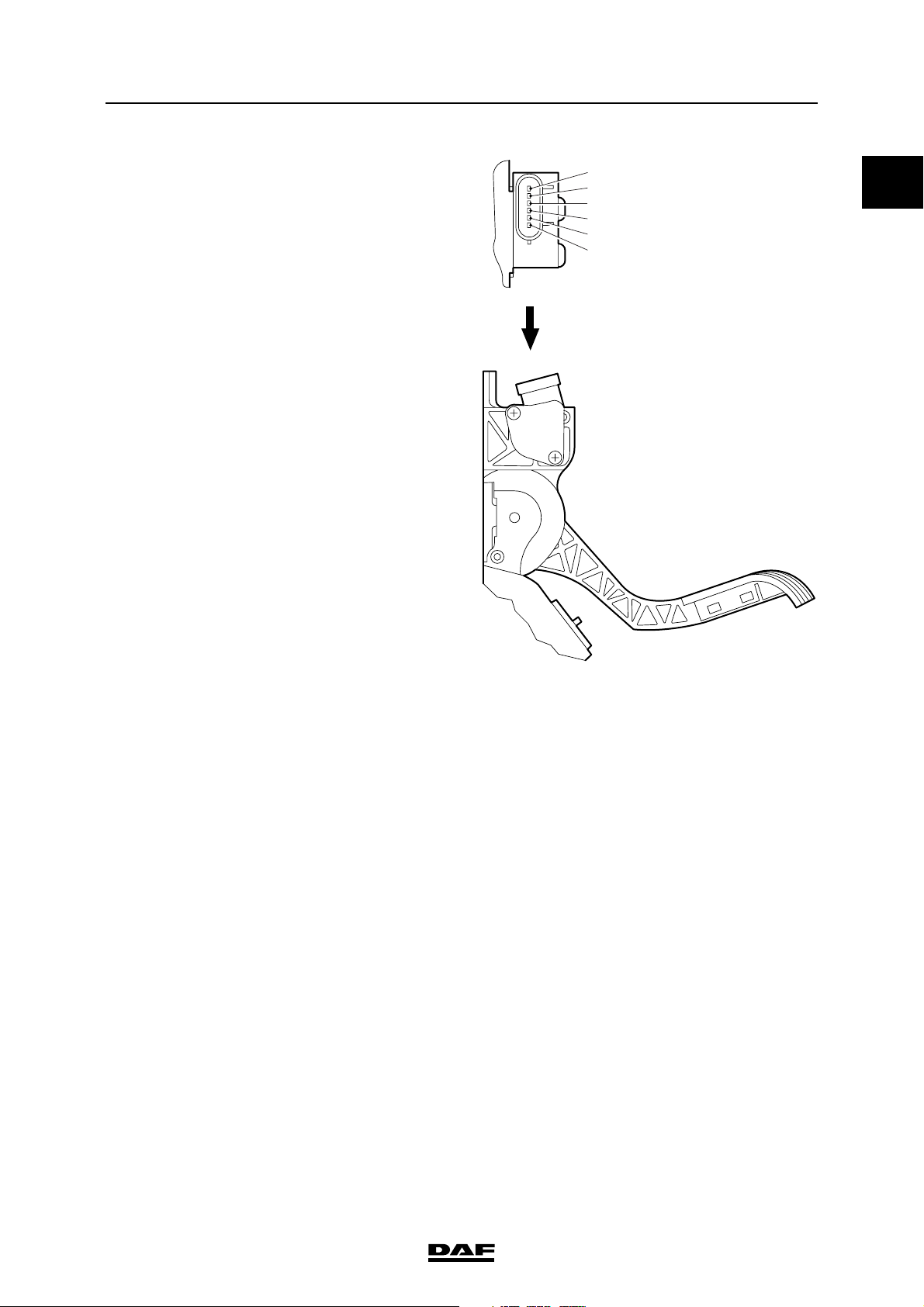
1.4 ACCELERATOR PEDAL SENSOR
A
C
B
A Electronic unit connection point
B Description of connection point
C Reading at connection point (Ubat = battery voltage)
D Measuring unit
E Explanatory notes (if applicable)
F Additional information available in Technical Data at "X" mark
29
33
37
41
45
49
53
57
60 62
1 45913172125
i400726
AB CDE F
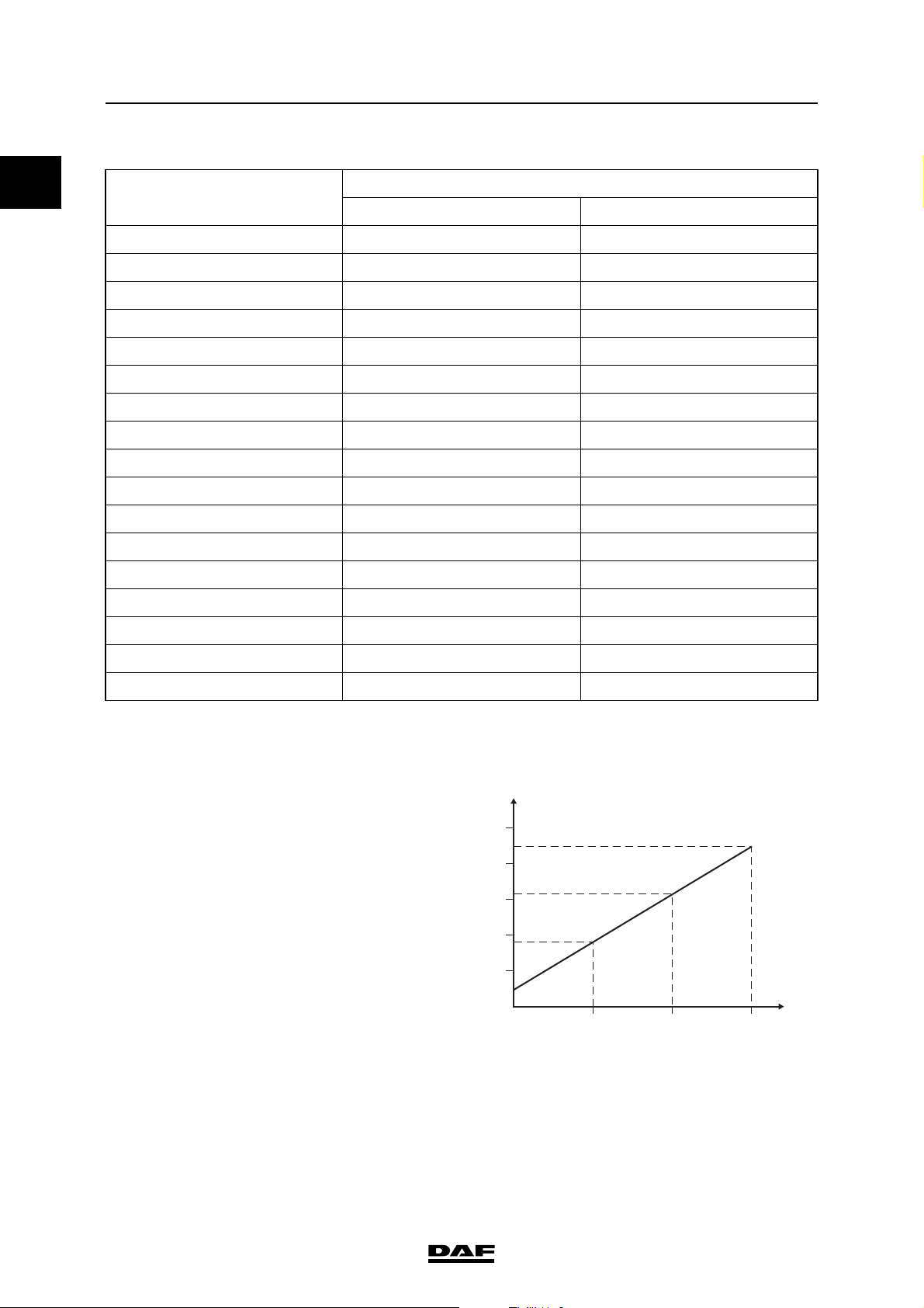
B33 Input signal accelerator pedal
sensor (F672)
0.325 -
0.500
0.675 -
V DC Idling, accelerator pedal not operated
(0%)
V DC Switching point idling switch (circa 10%) X
X
0.875
3.000 -
V DC Full load (circa 85%) X
3.400
3.550 -
V DC Kickdown (circa 100%) X
4.265
B34 Power supply, accelerator
5V DC
pedal sensor (F672)
B37 Earth, accelerator pedal
0V DC
sensor (F672)
B38 Accelerator pedal sensor
0V DC
earth, idling switch (F672)
B41 Accelerator pedal sensor input
signal, idling switch (F672)
1-4
5 V DC Accelerator pedal not operated X
0 V DC Accelerator pedal operated circa 10% X
©
200528
Page 13
TECHNICAL DATA
XF105 series
Potentiometer resistance
value (B - C)
Potentiometer output
resistance value (A - B)
Potentiometer output
resistance value (A - C)
Resistance value across
idling switch (open position)
Resistance value across
idling switch (closed position)
(1) Accelerator pedal not operated
(2) Accelerator pedal operated
(1)
(1)
(1)
(2)
1000 ≥ 40%
1500 ≥ 40%
2500 ≥ 40%
1000 ≥ 40%
DMCI engine management system
A
B
C
D
E
F
0
A. Potentiometer signal
B. Mass
C. Potentiometer supply voltage
D. Idling switch earth
E. Not in use
F. Idling switch signal
I400438
©
200528 1-5
Page 14
0
TECHNICAL DATA
DMCI engine management system XF105 series
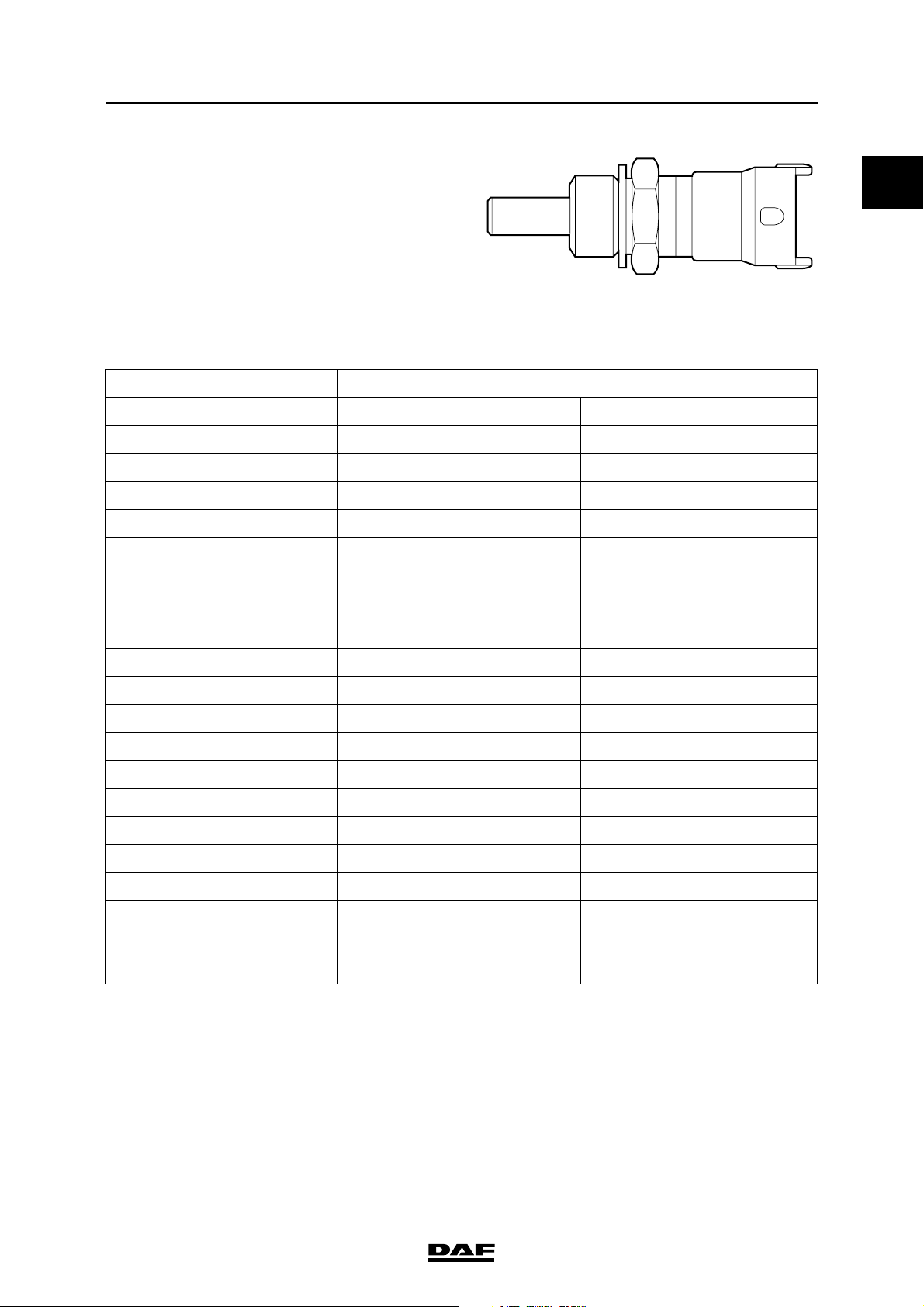
1.5 COOLANT TEMPERATURE SENSOR
A
C
A Electronic unit connection point
B Description of connection point
C Reading at connection point (Ubat = battery voltage)
D Measuring unit
B
21
25
29
33
37
41
45
49
53
57
60 62
1 4591317
i400726
E Explanatory notes (if applicable)
F Additional information available in Technical Data at "X" mark
AB C D E F
C25 Input signal, coolant temperature
(F566)
C26 Earth, coolant temperature sensor
5 V DC Open voltage, with detached
connector
0V DC
X
(F566)
1-6
©
200528
Page 15
TECHNICAL DATA
XF105 series
Coolant temperature sensor
Model NTC
Resistance in relation to measured temperature
Temperature (C) Resistance ()
Minimum Maximum
- 40 38313 52926
- 30 22307 30194
-20 13402 17718
-10 8244 10661
0 5227 6623
DMCI engine management system
0
i 400440
(1)
10 3390 4217
20 2262 2760
25 1870 2260
30 1553 1866
40 1080 1277
50 771 900
60 555 639
70 408 465
80 304 342
90 230 257
100 178 196
110 136 152
120 106 119
130 84 95
140 67 76
(1) Check the resistance by measuring on the connection points of the sensor.
©
200528 1-7
Page 16

TECHNICAL DATA
DMCI engine management system XF105 series
0
1.6 2
nd
COOLANT TEMPERATURE SENSOR
A
C
B
21
25
29
33
37
41
45
49
53
57
60 62
1 4591317
i400726
A Electronic unit connection point
B Description of connection point
C Reading at connection point (Ubat = battery voltage)
D Measuring unit
E Explanatory notes (if applicable)
F Additional information available in Technical Data at "X" mark
AB C D E F
A37 Input signal, coolant temperature
(F743)
A38 Earth, coolant temperature sensor
5 V DC Open voltage, with detached
connector
0V DC
X
(F743)
1-8
©
200528
Page 17
TECHNICAL DATA
XF105 series
Resistance in relation to measured temperature
Temperature (C) Resistance ()
Minimum Maximum
- 40 87134 98852
- 30 44876 50910
-20 24215 27471
-10 13703 15545
0 7914 8978
10 4752 5390
20 2948 3344
40 1224 1388
50 8167 927
60 558 632
70 390 442
80 278 311
DMCI engine management system
0
90 201 227
100 148 168
110 110 124
120 83 95
Coolant temperature sensor
Model NTC
i401003
©
200528 1-9
Page 18

0
TECHNICAL DATA
DMCI engine management system XF105 series
1.7 INLET AIR BOOST PRESSURE AND TEMPERATURE SENSOR
A
C
A Electronic unit connection point
B Description of connection point
C Reading at connection point (Ubat = battery voltage)
D Measuring unit
B
21
25
29
33
37
41
45
49
53
57
60 62
1 4591317
i400726
E Explanatory notes (if applicable)
F Additional information available in Technical Data at "X" mark
AB C D E F
A27 Earth air inlet boost pressure and
0V DC
temperature sensor (F649)
A28 Supply voltage air inlet boost
pressure and temperature sensor
5 V DC Open voltage, with detached
connector
(F649)
A30 Input signal air inlet boost pressure
(F649)
A34 Input signal air inlet temperature
(F649)
1-10
0.5 V DC Air inlet pressure 0 bar X
4.5 V DC Air inlet pressure 4 bar X
5 V DC Open voltage, with detached
connector
©
200528
X
Page 19
TECHNICAL DATA
XF105 series
Colour of O-ring green
Type of temperature sensor NTC
Resistance value See table
DMCI engine management system
0
P
U
T
R
1. Mass
2. Temperature sensor output signal
3. Pressure sensor supply voltage
4. Pressure sensor output signal
i 400441
3
4
2
1
i400534
©
200528 1-11
Page 20
TECHNICAL DATA
DMCI engine management system XF105 series
0
Resistance in relation to measured temperature
Temperature (C) Resistance ()
Minimum Maximum
- 40 38313 52926
- 30 22307 30194
-20 13402 17718
-10 8244 10661
0 5227 6623
10 3390 4217
20 2262 2760
25 1870 2260
30 1553 1866
40 1080 1277
50 771 900
60 555 639
70 408 465
80 304 342
(1)
90 230 257
100 178 196
110 136 152
120 106 119
130 84 95
140 67 76
(1) Check the resistance by measuring on connection points 1 and 2 of the sensor.
Type of pressure sensor piezoresistive
Pressure sensor output signal See graph
U
(V)
5
4
3
2
1-12
1
P
1 2 34
(bar)
i400836
©
200528
Page 21
TECHNICAL DATA
XF105 series
DMCI engine management system
1.8 FUEL PRESSURE AND TEMPERATURE SENSOR
A
C
B
0
21
25
29
33
37
41
45
49
53
57
60 62
1 4591317
i400726
A Electronic unit connection point
B Description of connection point
C Reading at connection point (Ubat = battery voltage)
D Measuring unit
E Explanatory notes (if applicable)
F Additional information available in Technical Data at "X" mark
AB C D E F
A41 Input signal fuel temperature (F713). 5 V DC Open voltage, with detached
X
connector
A42 Supply voltage fuel pressure and
temperature sensor (F713)
5 V DC Open voltage, with detached
connector
A45 Input signal fuel pressure (F713) 0.5 V DC Fuel pressure 0 bar X
4.5 V DC Fuel pressure 15 bar X
A46 Earth, fuel pressure and temperature
0V DC
sensor (F713)
©
200528 1-13
Page 22
TECHNICAL DATA
DMCI engine management system XF105 series
0
Gasket Copper ring
P
2
1
U
3
T
R
4
i400791
1. Pressure sensor supply voltage
2. Pressure sensor output signal
3. Temperature sensor output signal
4. Mass
Type of temperature sensor NTC
13
42
i400792
1-14
©
200528
Page 23
TECHNICAL DATA
XF105 series
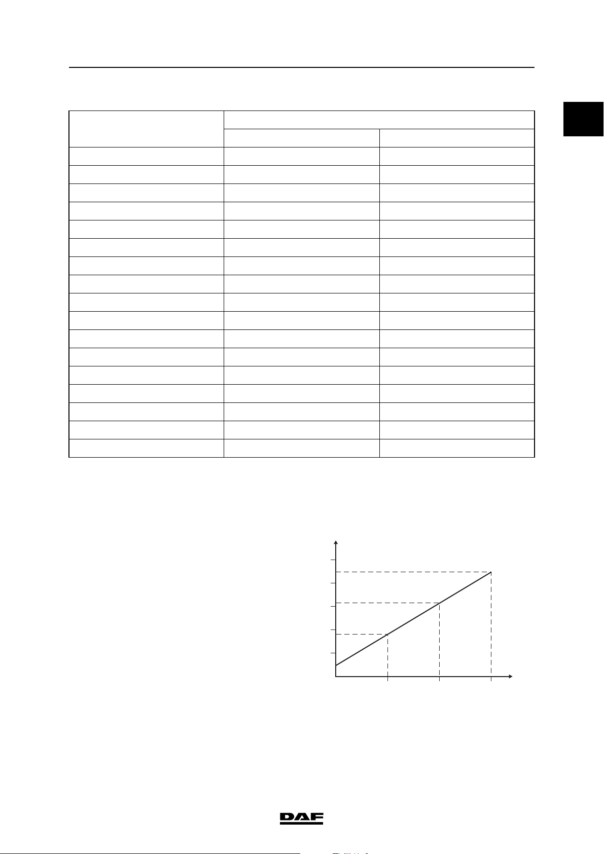
Temperature sensor resistance value
Temperature (C) Resistance ()
- 30 24351 30653.2
- 20 13431 16594
- 10 7850 9095
0 4488 5372
10 2740 3236
20 1727 2010
30 1120 1291
40 746 850
50 510 574
60 355 396
70 253 279
80 185 198
DMCI engine management system
(1)
0
Minimum Maximum
90 134 145
100 100 107
110 75 81
120 57 62
130 44 48
(1) Check the resistance by measuring on connection points 3 and 4 of the sensor.
Type of pressure sensor piezo-capacitive
Voltage signal pressure sensor
U
(V)
5
4
3
2
1
5 10 15
©
200528 1-15
(bar)
P
i400835
Page 24
0
TECHNICAL DATA
DMCI engine management system XF105 series
1.9 ENGINE OIL PRESSURE AND TEMPERATURE SENSOR
A
C
A Electronic unit connection point
B Description of connection point
C Reading at connection point (Ubat = battery voltage)
D Measuring unit
B
21
25
29
33
37
41
45
49
53
57
60 62
1 4591317
i400726
E Explanatory notes (if applicable)
F Additional information available in Technical Data at "X" mark
AB C D E F
C29 Input signal engine oil temperature
(F744)
C30 Supply voltage engine oil pressure
and temperature sensor (F744)
C33 Input signal engine oil pressure
(F744)
C34 Earth, engine oil pressure and
5 V DC Open voltage, with detached
connector
5 V DC Open voltage, with detached
connector
0.5 V DC Engine oil pressure 0 bar X
4.5 V DC Engine oil pressure 15 bar X
0V DC
X
temperature sensor (F744)
1-16
©
200528
Page 25
TECHNICAL DATA
XF105 series
Gasket Copper ring
DMCI engine management system
0
13
42
i400792
2
1. Pressure sensor supply voltage
2. Pressure sensor output signal
3. Temperature sensor output signal
4. Mass
Type of temperature sensor NTC
P
U
1
3
T
R
4
i400791
©
200528 1-17
Page 26
TECHNICAL DATA
DMCI engine management system XF105 series
0
Resistance in relation to measured temperature
Temperature (C) Resistance ()
Minimum Maximum
- 30 24351 30653
- 20 13431 16594
- 10 7850 9095
0 4488 5372
10 2740 3236
20 1727 2010
30 1120 1295
40 746 850
50 510 574
60 355 396
70 253 279
80 185 198
90 134 145
100 100 107
(1)
110 75 81
120 57 62
130 44 48
(1) Check the resistance by measuring on connection points 3 and 4 of the sensor.
Type of pressure sensor piezo-capacitive
U
(V)
5
4
3
2
1
5 10 15
P
(bar)
i400835
1-18
©
200528
Page 27

TECHNICAL DATA
XF105 series
1.10 CRANKSHAFT SENSOR
A
C
DMCI engine management system
21
25
29
33
37
41
45
49
53
57
60 62
1 4591317
B
0
i400726
A Electronic unit connection point
B Description of connection point
C Reading at connection point (Ubat = battery voltage)
D Measuring unit
E Explanatory notes (if applicable)
F Additional information available in Technical Data at "X" mark
AB CDE F
A49 Input signal, crankshaft sensor (F552) - Hz /
(VAC)
Frequency depends on
engine speed
X
A50 Earth, crankshaft sensor (F552) 0 V DC
A60 Shield signal crankshaft sensor (F552) 0 V DC
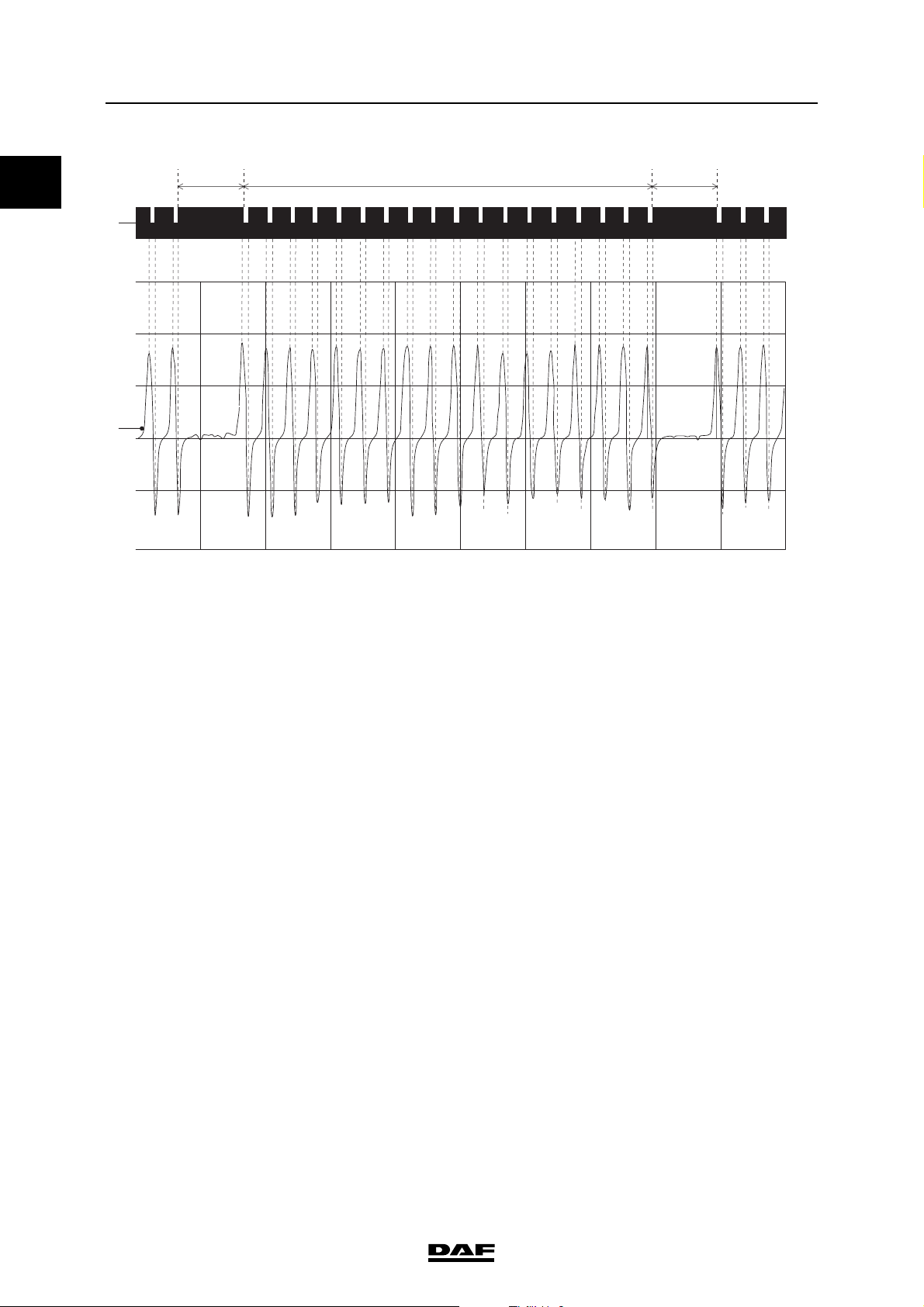
Type Inductive
Signal version sine-wave alternating voltage
Total number of pulses per crankshaft revolution 54
Number of cylinder detection pulses per
crankshaft revolution 3
Effective voltage when starting approx. 1.5 V
Effective voltage when idling approx. 4.0 V
Effective voltage at 1200 rpm approx. 7.0 V
Resistance value 860 ≥ 10% at 20C
(1)
(1)
(1)
(2)
(1) Measurements taken with multimeter in "AC voltage" position (VAC).
(2) Measured on connection points 1 and 2 of the sensor.
©
200528 1-19
Page 28
TECHNICAL DATA
DMCI engine management system XF105 series
0
ab
1
2
1. Flywheel
a. Area with two holes missing
b. Segment with 18 holes
c. Area with two holes missing
2. Crankshaft sensor signal
c
I400732
1-20
©
200528
Page 29
TECHNICAL DATA
XF105 series
1.11 CAMSHAFT SENSOR
A
C
DMCI engine management system
21
25
29
33
37
41
45
49
53
57
60 62
1 4591317
B
0
i400726
A Electronic unit connection point
B Description of connection point
C Reading at connection point (Ubat = battery voltage)
D Measuring unit
E Explanatory notes (if applicable)
F Additional information available in Technical Data at "X" mark
AB CDE F
A53 Input signal camshaft sensor (F558) - Hz /
(VAC)
Frequency depends on the
speed
X
A54 Earth, camshaft sensor (F558) 0 V DC
A61 Shield signal camshaft sensor (F558) 0 V DC
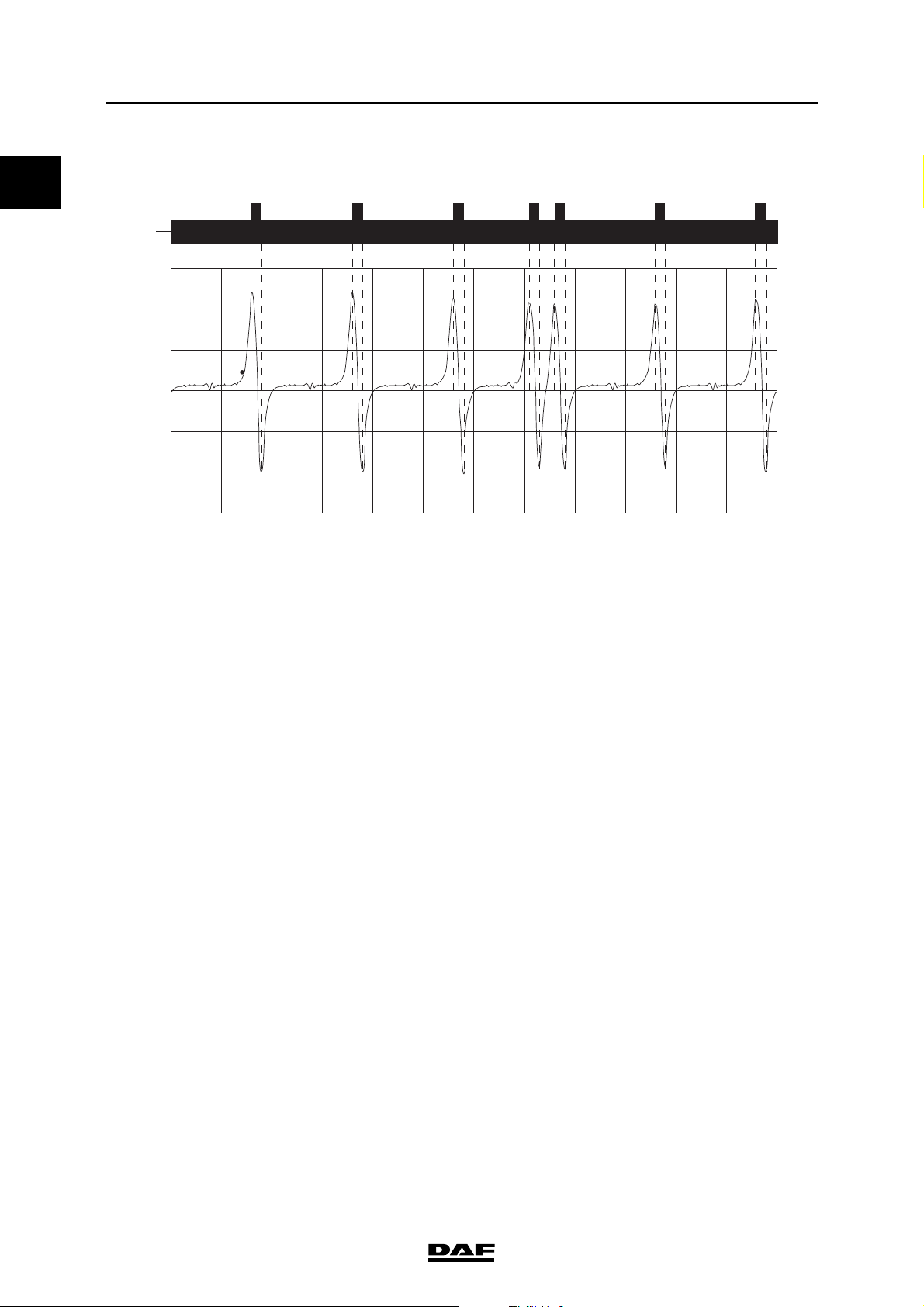
Type Inductive
Signal version sine-wave alternating voltage
Total number of pulses for every two crankshaft
revolutions 7
Effective voltage when starting approx. 0.5 V
Effective voltage when idling approx. 2.0 V
Effective voltage at 1200 rpm approx. 4.0 V
Resistance value 860 ≥ 10% at 20C
(1)
(1)
(1)
(2)
(1) Measurements taken with multimeter in "AC voltage" position (VAC).
(2) Measured on connection points 1 and 2 of the sensor.
©
200528 1-21
Page 30
TECHNICAL DATA
DMCI engine management system XF105 series
0
624s153
a
b
0
I400762
a. Pulse wheel
b. Camshaft sensor signal
1-22
©
200528
Page 31

TECHNICAL DATA
XF105 series
1.12 ENGINE OIL LEVEL SENSOR
A
C
DMCI engine management system
21
25
29
33
37
41
45
49
53
57
60 62
1 4591317
B
0
i400726
A Electronic unit connection point
B Description of connection point
C Reading at connection point (Ubat = battery voltage)
D Measuring unit
E Explanatory notes (if applicable)
F Additional information available in Technical Data at "X" mark
AB C D E F
B13 Output and input signal oil level
sensor (F673)
- V DC Voltage increase or decrease
depending on the oil level and the
oil temperature
B14 Earth oil level sensor (F673) 0 V DC
©
200528 1-23
Page 32

TECHNICAL DATA
DMCI engine management system XF105 series
0
Supply voltage approx. 24 V
Resistance value (at 20C) 20.5 - 23.5
(1) During the measurement of the resistance value the
current may not be more than 200mA.
(1)
E501146
1-24
©
200528
Page 33

TECHNICAL DATA
XF105 series
1.13 SWITCHES (MANUAL GEARBOX)
A
C
DMCI engine management system
21
25
29
33
37
41
45
49
53
57
60 62
1 4591317
B
0
i400726
A Electronic unit connection point
B Description of connection point
C Reading at connection point (Ubat = battery voltage)
D Measuring unit
E Explanatory notes (if applicable)
F Additional information available in Technical Data at "X" mark
AB CDE F
B36 Input signal clutch switch (E575) 0 V DC Clutch pedal not depressed
Ubat V DC Clutch pedal fully depressed
B40 Input signal neutral position switch (E593) Ubat V DC Gearbox in neutral:
0 V DC Gear box in gear
Clutch switch
Model Hall proximity switch
Neutral position switch
Model Normally Open
©
200528 1-25
Page 34

0
TECHNICAL DATA
DMCI engine management system XF105 series
1.14 SWITCHES (AS TRONIC)
A
C
A Electronic unit connection point
B Description of connection point
C Reading at connection point (Ubat = battery voltage)
D Measuring unit
B
21
25
29
33
37
41
45
49
53
57
60 62
1 4591317
i400726
E Explanatory notes (if applicable)
F Additional information available in Technical Data at "X" mark
AB C D E F
B40 Input signal neutral position switch
(E599)
0 V DC Gearbox in neutral
Ubat V DC Gear box in gear
Neutral position switch
Model Normally Closed
1-26
©
200528
Page 35

TECHNICAL DATA
XF105 series
DMCI engine management system
1.15 EXTRA BULKHEAD LEAD-THROUGH FUNCTIONS
A
C
B
0
21
25
29
33
37
41
45
49
53
57
60 62
1 4591317
i400726
A Electronic unit connection point
B Description of connection point
C Reading at connection point (Ubat = battery voltage)
D Measuring unit
E Explanatory notes (if applicable)
F Additional information available in Technical Data at "X" mark
AB C D E F
B1 Output signal engine speed (bulkhead
lead-through connector 12C:3)
- Hz Frequency depends on engine
speed (30 pulses per crankshaft
revolution)
B8 Input signal torque limitation 1 (bulk-
head lead-through connector 12C:17)
B11 Input signal torque limitation 2 (bulk-
head lead-through connector 12C:20)
Ubat V DC Only active after release. Not
programmable with DAVIE XD
Ubat V DC Only active after release. Not
programmable with DAVIE XD
X
X
Connection point B8 Connection point B11 Torque limiting during engine
speed control
Ubat 0 Level 1: 1800 Nm
0 Ubat Level 2: 1200 Nm
Ubat Ubat Level 3: 600 Nm
©
200528 1-27
Page 36

0
TECHNICAL DATA
DMCI engine management system XF105 series
1.16 RED WARNING
A
C
A Electronic unit connection point
B Description of connection point
C Reading at connection point (Ubat = battery voltage)
B
21
25
29
33
37
41
45
49
53
57
60 62
1 4591317
i400726
D Measuring unit
E Explanatory notes (if applicable)
F Additional information available in Technical Data at "X" mark
AB C D E F
B22 Output signal red warning to VIC-2
(D310)
Ubat VDC No red warning
0 - 5 VDC Red warning active (always in
combination with a CAN
message)
1-28
©
200528
Page 37

TECHNICAL DATA
XF105 series
1.17 STARTER MOTOR
A
C
DMCI engine management system
21
25
29
33
37
41
45
49
53
57
60 62
1 4591317
B
0
i400726
A Electronic unit connection point
B Description of connection point
C Reading at connection point (Ubat = battery voltage)
D Measuring unit
E Explanatory notes (if applicable)
F Additional information available in Technical Data at "X" mark
AB C D E F
B9 Output signal earth starter motor
(B010)
0 VDC If starter motor is active
about
VDC If engine is running
1.5
©
200528 1-29
Page 38

0
TECHNICAL DATA
DMCI engine management system XF105 series
1.18 GLOW COMPONENTS
A
C
A Electronic unit connection point
B Description of connection point
C Reading at connection point (Ubat = battery voltage)
D Measuring unit
B
21
25
29
33
37
41
45
49
53
57
60 62
1 4591317
i400726
E Explanatory notes (if applicable)
F Additional information available in Technical Data at "X" mark
AB C D E F
C32 Output signal glow relay (G014) 0 V DC Glow relay active
Ubat V DC Glow relay not active
C39 Input signal glow relay active (G014) Ubat V DC Glow relay activated
0 V DC Glow relay not active
Glow plug relay
Supply voltage Ubat
Resistance value of coil 21 ≥ 10%
Glow element
Supply voltage Ubat
Rated output 1.9 kW ≥ 10%
Resistance value 0.25 ≥ 10%
1-30
©
200528
Page 39

TECHNICAL DATA
XF105 series
1.19 WASTE GATE VALVE
A
C
DMCI engine management system
21
25
29
33
37
41
45
49
53
57
60 62
1 4591317
B
0
i400726
A Electronic unit connection point
B Description of connection point
C Reading at connection point (Ubat = battery voltage)
D Measuring unit
E Explanatory notes (if applicable)
F Additional information available in Technical Data at "X" mark
AB C D E F
C8 Output signal waste gate valve
(B368)
- % Depending on the desired boost
pressure, earth-controlled duty
X
cycle
C59 Earth waste gate valve (B368) 0 V DC
©
200528 1-31
Page 40

TECHNICAL DATA
DMCI engine management system XF105 series
0
Supply voltage approx. 24 V
Air pressure approx. 10 bar
Control signal earth-controlled
duty cycle
Duty cycle voltage level approx. 12 V
Frequency of duty
cycle signal circa 160 Hz
(1) Check duty cycle with the multimeter by plus
measurement pin at C59 and less measurement pin
at C8.
Duty cycle (%) Output pressure, output
00.30.3
10 0.3 0.3
(1)
10% duty cycle, earth-controlled, plus
measurement pin C8 less measurement pin
C59
U (V)
25
20
15
10
5
0
MX375 MX410
Output pressure, output
"2" (bar)
"2" (bar)
i401021
50 1.5 2.5
90 3.0 5.0
95 3.0 5.0
100 0.3 0.3
1-32
©
200528
Page 41

TECHNICAL DATA
XF105 series
1.20 EXHAUST BRAKE VALVE
A
C
DMCI engine management system
21
25
29
33
37
41
45
49
53
57
60 62
1 4591317
B
0
i400726
A Electronic unit connection point
B Description of connection point
C Reading at connection point (Ubat = battery voltage)
D Measuring unit
E Explanatory notes (if applicable)
F Additional information available in Technical Data at "X" mark
AB C D E F
C28 Output signal exhaust brake valve
(B192)
Ubat VDC Exhaust brake valve not active
0 VDC Exhaust brake valve active
Resistance value 56 ≥ 10%
©
200528 1-33
Page 42

0
TECHNICAL DATA
DMCI engine management system XF105 series
1.21 DEB SOLENOID VALVE
A
C
A Electronic unit connection point
B Description of connection point
C Reading at connection point (Ubat = battery voltage)
D Measuring unit
B
21
25
29
33
37
41
45
49
53
57
60 62
1 4591317
i400726
E Explanatory notes (if applicable)
F Additional information available in Technical Data at "X" mark
AB C D E F
A35 Earth magnetic valve DEB (B411) 0 V DC
A36 Output signal magnetic valve DEB
(B411)
Ubat V DC DEB active
0 V DC DEB not active
A39 Earth magnetic valve DEB (B415) 0 V DC
A40 Output signal magnetic valve DEB
(B415)
Ubat V DC DEB active
0 V DC DEB not active
A43 Earth magnetic valve DEB (B413) 0 V DC
A44 Output signal magnetic valve DEB
(B413)
Ubat V DC DEB active
0 V DC DEB not active
A47 Earth magnetic valve DEB (B416) 0 V DC
1-34
©
200528
Page 43

TECHNICAL DATA
XF105 series
AB C D E F
A48 Output signal magnetic valve DEB
(B416)
A51 Earth magnetic valve DEB (B412) 0 V DC
A52 Output signal magnetic valve DEB
(B412)
A55 Earth magnetic valve DEB (B414) 0 V DC
A56 Output signal magnetic valve DEB
(B414)
Resistance value 40 ≥ 10%
(1) Check the resistance by measuring at the valve connection points to the correct connection points of the in-line connectors.
Ubat V DC DEB active
0 V DC DEB not active
Ubat V DC DEB active
0 V DC DEB not active
Ubat V DC DEB active
0 V DC DEB not active
DMCI engine management system
(1)
0
©
200528 1-35
Page 44

0
TECHNICAL DATA
DMCI engine management system XF105 series
1.22 PUMP UNIT
A
C
A Electronic unit connection point
B Description of connection point
C Reading at connection point (Ubat = battery voltage)
D Measuring unit
B
21
25
29
33
37
41
45
49
53
57
60 62
1 4591317
i400726
E Explanatory notes (if applicable)
F Additional information available in Technical Data at "X" mark
AB C D E F
A03 Output signal high pump unit
- V DC See scope example X
cylinder 1 (B131)
A04 Output signal low pump unit
- V DC See scope example X
cylinder 1 (B131)
A07 Output signal high pump unit
- V DC See scope example X
cylinder 3 (B133)
A08 Output signal low pump unit
- V DC See scope example X
cylinder 5 (B135)
A11 Output signal high pump unit
- V DC See scope example X
cylinder 2 (B132)
A12 Output signal low pump unit
- V DC See scope example X
cylinder 3 (B133)
A15 Output signal high pump unit
- V DC See scope example X
cylinder 5 (B135)
1-36
©
200528
Page 45

TECHNICAL DATA
XF105 series
AB C D E F
A16 Output signal low pump unit
cylinder 6 (B136)
A19 Output signal high pump unit
cylinder 6 (B136)
A20 Output signal low pump unit
cylinder 2 (B132)
A23 Output signal low pump unit
cylinder 4 (B134)
A24 Output signal high pump unit
cylinder 4 (B134)
Pick-up voltage approx. 50 V
Withstand voltage approx. 24 V
- V DC See scope example X
- V DC See scope example X
- V DC See scope example X
- V DC See scope example X
- V DC See scope example X
DMCI engine management system
U (V)
60
40
20
0
0
Solenoid valve resistance value
-40C1.1
20C1.6
120C2.4
(1) Check the resistance by measuring on the connection points of the pump unit.
(1)
i400845
©
200528 1-37
Page 46

0
TECHNICAL DATA
DMCI engine management system XF105 series
1.23 INJECTOR
A
C
A Electronic unit connection point
B Description of connection point
C Reading at connection point (Ubat = battery voltage)
D Measuring unit
B
21
25
29
33
37
41
45
49
53
57
60 62
1 4591317
i400726
E Explanatory notes (if applicable)
F Additional information available in Technical Data at "X" mark
AB C D E F
A01 Output signal low injector cylinder 1
V DC See scope example
(B421)
A02 Output signal high injector cylinder 1
V DC See scope example
(B421)
A05 Output signal low injector cylinder 5
V DC See scope example
(B425)
A06 Output signal high injector cylinder 3
V DC See scope example
(B423)
A09 Output signal low injector cylinder 3
V DC See scope example
(B423)
A10 Output signal high injector cylinder 2
V DC See scope example
(B422)
A13 Output signal low injector cylinder 6
V DC See scope example
(B426)
1-38
©
200528
Page 47

TECHNICAL DATA
XF105 series
AB C D E F
A14 Output signal high injector cylinder 5
(B425)
A17 Output signal low injector cylinder 2
(B422)
A18 Output signal high injector cylinder 6
(B426)
A21 Output signal low injector cylinder 4
(B424)
A22 Output signal high injector cylinder 4
(B424)
Pick-up voltage approx. 50 V
Withstand voltage approx. 24 V
DMCI engine management system
V DC See scope example
V DC See scope example
V DC See scope example
V DC See scope example
V DC See scope example
U (V)
60
40
20
0
0
i400846
Solenoid valve resistance value
-40C1.1
20C1.6
120C2.4
(1) Check the resistance by measuring at the injector connection points to the correct connection points of the in-line connectors.
(1)
©
200528 1-39
Page 48

0
TECHNICAL DATA
DMCI engine management system XF105 series
1.24 ELECTRONICALLY CONTROLLED FAN CLUTCH
A
C
A Electronic unit connection point
B Description of connection point
C Reading at connection point (Ubat = battery voltage)
D Measuring unit
B
21
25
29
33
37
41
45
49
53
57
60 62
1 4591317
i400726
E Explanatory notes (if applicable)
F Additional information available in Technical Data at "X" mark
AB C D E F
C16 Output signal fan clutch control - % Earth-controlled duty cycle X
Ubat VDC Ignition on
C31 Fan clutch speed sensor earth 0 VDC
C35 Fan clutch speed sensor power
5VDC
supply
C36 Fan clutch speed sensor input signal - Hz Square wave signal X
1-40
©
200528
Page 49

TECHNICAL DATA
XF105 series
Type of speed sensor Hall
Speed sensor output signal Square-wave
signal 5 V
Frequency at 1000 rpm fan
speed 100 Hz
Pulses per fan revolution 6
Fan clutch control earth-controlled
duty cycle
(0 - 100%
Duty cycle voltage level 24 V
Frequency of duty
cycle signal 2 Hz
Duty cycle high
Duty cycle low
(1)
(1)
Decreasing fan
speed
Increasing fan
speed
DMCI engine management system
U (V)
6
4
2
0
U (V)
25
20
15
10
5
0
0
i400848
(1) Measured with plus probe on pin B60 and minus probe on
pin C16
1. Fan speed sensor output signal
2. Fan speed sensor earth
3. Fan clutch control signal
4. Fan clutch supply voltage 24V
5. Fan speed sensor supply voltage 5V
i400847
5
4
3
1
2
i 400456
©
200528 1-41
Page 50

0
TECHNICAL DATA
DMCI engine management system XF105 series
1-42
©
200528
Page 51

DMCI ENGINE MANAGEMENT SYSTEM
XF105 series
Contents
CONTENTS
Page Date
1. SYSTEM DESCRIPTION . . . . . . . . . . . . . . . . . . . . . . . . . . . . . . . . . . . . . . . . . . 1-1 . . . . . 200528
1.1 Introduction . . . . . . . . . . . . . . . . . . . . . . . . . . . . . . . . . . . . . . . . . . . . . . . . 1-1 . . . . . 200528
1.2 Electrical system . . . . . . . . . . . . . . . . . . . . . . . . . . . . . . . . . . . . . . . . . . . . 1-2 . . . . . 200528
1.3 System description of fuel system . . . . . . . . . . . . . . . . . . . . . . . . . . . . . . . 1-5 . . . . . 200528
2. DESCRIPTION OF COMPONENTS . . . . . . . . . . . . . . . . . . . . . . . . . . . . . . . . . . 2-1 . . . . . 200528
2.1 DMCI electronic unit . . . . . . . . . . . . . . . . . . . . . . . . . . . . . . . . . . . . . . . . . 2-1 . . . . . 200528
2.2 Accelerator pedal sensor . . . . . . . . . . . . . . . . . . . . . . . . . . . . . . . . . . . . . . 2-2 . . . . . 200528
2.3 Coolant temperature sensor . . . . . . . . . . . . . . . . . . . . . . . . . . . . . . . . . . . 2-4 . . . . . 200528
2.4 2
2.5 Inlet air boost pressure and temperature sensor. . . . . . . . . . . . . . . . . . . . 2-5 . . . . . 200528
2.6 Fuel pressure and temperature sensor . . . . . . . . . . . . . . . . . . . . . . . . . . . 2-7 . . . . . 200528
2.7 Engine oil pressure and temperature sensor. . . . . . . . . . . . . . . . . . . . . . . 2-8 . . . . . 200528
2.8 Crankshaft sensor . . . . . . . . . . . . . . . . . . . . . . . . . . . . . . . . . . . . . . . . . . . 2-9 . . . . . 200528
2.9 Camshaft sensor . . . . . . . . . . . . . . . . . . . . . . . . . . . . . . . . . . . . . . . . . . . . 2-12 . . . . 200528
2.10 Waste gate valve . . . . . . . . . . . . . . . . . . . . . . . . . . . . . . . . . . . . . . . . . . . . 2-15 . . . . 200528
2.11 Pump unit . . . . . . . . . . . . . . . . . . . . . . . . . . . . . . . . . . . . . . . . . . . . . . . . . 2-17 . . . . 200528
2.12 Injector. . . . . . . . . . . . . . . . . . . . . . . . . . . . . . . . . . . . . . . . . . . . . . . . . . . . 2-23 . . . . 200528
2.13 Electronically controlled fan clutch . . . . . . . . . . . . . . . . . . . . . . . . . . . . . . 2-27 . . . . 200528
nd
coolant temperature sensor. . . . . . . . . . . . . . . . . . . . . . . . . . . . . . . . . 2-4 . . . . . 200528
1
3. CONTROL FUNCTIONS. . . . . . . . . . . . . . . . . . . . . . . . . . . . . . . . . . . . . . . . . . . 3-1 . . . . . 200528
3.1 System status . . . . . . . . . . . . . . . . . . . . . . . . . . . . . . . . . . . . . . . . . . . . . . 3-1 . . . . . 200528
3.2 CAN controls . . . . . . . . . . . . . . . . . . . . . . . . . . . . . . . . . . . . . . . . . . . . . . . 3-3 . . . . . 200528
3.3 Pre-glowing and after-glowing . . . . . . . . . . . . . . . . . . . . . . . . . . . . . . . . . . 3-5 . . . . . 200528
3.4 Immobiliser and start interruption . . . . . . . . . . . . . . . . . . . . . . . . . . . . . . . 3-7 . . . . . 200528
3.5 Cylinder detection and synchronisation . . . . . . . . . . . . . . . . . . . . . . . . . . . 3-9 . . . . . 200528
3.6 Fuel injection when starting . . . . . . . . . . . . . . . . . . . . . . . . . . . . . . . . . . . . 3-14 . . . . 200528
3.7 Injection timing control . . . . . . . . . . . . . . . . . . . . . . . . . . . . . . . . . . . . . . . . 3-15 . . . . 200528
3.8 Idling control . . . . . . . . . . . . . . . . . . . . . . . . . . . . . . . . . . . . . . . . . . . . . . . 3-16 . . . . 200528
3.9 Turbocharger pressure control . . . . . . . . . . . . . . . . . . . . . . . . . . . . . . . . . 3-17 . . . . 200528
3.10 Smoke limitation . . . . . . . . . . . . . . . . . . . . . . . . . . . . . . . . . . . . . . . . . . . . 3-19 . . . . 200528
3.11 Engine brake control . . . . . . . . . . . . . . . . . . . . . . . . . . . . . . . . . . . . . . . . . 3-20 . . . . 200528
3.12 Fan clutch control . . . . . . . . . . . . . . . . . . . . . . . . . . . . . . . . . . . . . . . . . . . 3-24 . . . . 200528
3.13 Engine protection functions . . . . . . . . . . . . . . . . . . . . . . . . . . . . . . . . . . . . 3-27 . . . . 200528
3.14 Vehicle speed limiting functions . . . . . . . . . . . . . . . . . . . . . . . . . . . . . . . . 3-32 . . . . 200528
3.15 Cruise control . . . . . . . . . . . . . . . . . . . . . . . . . . . . . . . . . . . . . . . . . . . . . . 3-34 . . . . 200528
3.16 Downhill Speed Control . . . . . . . . . . . . . . . . . . . . . . . . . . . . . . . . . . . . . . . 3-37 . . . . 200528
3.17 Engine speed control. . . . . . . . . . . . . . . . . . . . . . . . . . . . . . . . . . . . . . . . . 3-40 . . . . 200528
4. DIAGRAMS . . . . . . . . . . . . . . . . . . . . . . . . . . . . . . . . . . . . . . . . . . . . . . . . . . . . . 4-1 . . . . . 200528
4.1 Key to block diagram DMCI . . . . . . . . . . . . . . . . . . . . . . . . . . . . . . . . . . . . 4-1 . . . . . 200528
4.2 Block diagram DMCI . . . . . . . . . . . . . . . . . . . . . . . . . . . . . . . . . . . . . . . . . 4-3 . . . . . 200528
©
200528 1
Page 52

1
DMCI ENGINE MANAGEMENT SYSTEM
Contents XF105 series
2
©
200528
Page 53

DMCI ENGINE MANAGEMENT SYSTEM
XF105 series
1. SYSTEM DESCRIPTION
1.1 INTRODUCTION
The design, functions and controls of the "DMCI"
engine management system are described in this
systems manual.
"DMCI" stands for DAF Multi Controlled Injection.
Fuel injection is controlled by an electronically
controlled pump unit and an electronically
controlled injector.
The pump unit is responsible for the fuel supply to
the injector. Injection timing is determined by the
injector. Injection quantity is determined by the
pump unit and injector in combination.
Of course, the DMCI electronic unit requires
various sensors to control these two components
correctly in order to determine the injection timing
and the correct quantity of fuel to be injected.
System description
1
©
200528 1-1
Page 54

1
DMCI ENGINE MANAGEMENT SYSTEM
System description XF105 series
1.2 ELECTRICAL SYSTEM
The electronic unit is the central control device of
the DMCI engine management system. The
functions can be split into engine functions and
vehicle functions.
Note:
Functions may be optional or may depend on the
vehicle configuration.
Engine functions:
- system status
-CAN controls
- pre-glowing and after-glowing
- control of fuel supply
- cylinder detection and synchronisation
- fuel injection when starting
- injection timing control
- idling control
- turbocharger pressure control
- smoke limitation
- full-load limiting and engine protection
functions
- engine brake control
- fan clutch control
Vehicle functions:
- Cruise control
- downhill speed control
- vehicle speed limiting prescribed by law
- variable vehicle speed limiting
- vehicle speed limiting for special applications
- engine speed control
-CAN controls
1-2
©
200528
Page 55

DMCI ENGINE MANAGEMENT SYSTEM
/
/
/
/
/
/
XF105 series
E575
CAN
network
F672
B335
F673G469
E593/
E599 F552F566
D965
B010
VIC
D310 D899
B368
F649F743
B192
F744
G014
System description
F713 F558
B411/
B412/
B413/
B414/
B415/
B416/
B421/
B422/
B423/
B424/
B425/
B426/
1
B131
B132
B133
B134
B135
B136
i400991
The DMCI electronic unit needs different input
signals to control engine and vehicle functions
and various components are activated by output
signals.
Input signals
The most important input signals are:
- clutch proximity switch (E575)
- service brake (G469)
- accelerator pedal sensor (F672)
- neutral position switch (F593/F599)
- oil level sensor (F673)
nd
-2
- coolant temperature sensor (F566)
- air inlet boost pressure and temperature
- engine oil pressure and temperature sensor
- fuel pressure and temperature sensor (F713)
- crankshaft sensor (F552)
- camshaft sensor (F558)
- electronically controlled fan clutch (B335)
- glow relay (G014)
coolant temperature sensor (F743)
sensor (F649)
(F744)
©
200528 1-3
Page 56

1
DMCI ENGINE MANAGEMENT SYSTEM
System description XF105 series
Output signals
After processing of the input signals, output
signals control the following components:
- electronically controlled fan clutch (B335)
- red warning VIC-2 (D310)
- waste gate valve (B368)
- starter motor (B010)
- exhaust brake valve (B192)
- DEB solenoid valves (B411 to B416)
- glow relay (G014)
- pump units (B131 to B136)
- injectors (B421 to B426)
The DMCI communicates with the various other
electronic systems in the vehicle via the CAN
network.
DAVIE XD is used to diagnose faults on the
DMCI.
1-4
©
200528
Page 57

DMCI ENGINE MANAGEMENT SYSTEM
XF105 series
1.3 SYSTEM DESCRIPTION OF FUEL SYSTEM
Fuel system
7
B
8
6
M M M M M M
A
66
77777
66
PUT
R
9
System description
6
c
b
5
a
c
4
b
a
1
d
2a2b
b
1
A Cylinder block 4 Fuel filter
B Cylinder head 4a Filter element
1 Fuel tank 4b Bleed restriction
1a Fuel-tank coarse filter 5 Fuel pressure control valve
2a Shut-off valve, supply 5a Pressure control flap
2b Shut-off valve, return 5b Throttle bleed/idling speed
3 Fuel pump 5c Fuel pressure measuring point
3a Lift pump 6 Pump units
3b Primer pump 7 Injectors
3c Pressure release valve 8 Non-return valve
3d Circulation valve 9 Fuel pressure and temperature sensor
The fuel lift pump (3a) draws fuel out of the fuel
tank (1) via a shut-off valve (2a) in the supply
pipe. The fuel goes to the fuel pump (3) via the
cylinder block (A). The fuel lift pump (3a) pumps
the fuel via the fuel filter (4) to the fuel gallery in
the cylinder block (A). The pressure in the fuel
a
a
M
3
i400749
©
200528 1-5
Page 58

DMCI ENGINE MANAGEMENT SYSTEM
System description XF105 series
gallery is controlled by the pressure control flap
(5a) in the fuel pressure control valve (5). The
valve (5a) opens at a specific pressure and
the fuel is led back to the intake side of the
fuel pump (3).
1
There is a calibrated opening (5b) in the fuel
pressure control valve (5) that ensures cooling of
the fuel system, by means of fuel flow-back, at
low engine speeds and in situations where fuel is
not injected (e.g. DEB in use). This calibrated
opening (5b) also ensures that pressure in the
fuel gallery is stable at low speeds and therefore
that pump pressures are low.
There is a test connection (5c) on the fuel
pressure control valve (5) for measuring the fuel
gallery pressure.
The fuel flows to the pump units (6) from the fuel
gallery. If the solenoid valve in the pump unit is
not activated, the pump unit pumps the fuel back
into the fuel gallery. If the solenoid valve in the
pump unit is activated, the fuel is pumped at high
pressure to the injectors (7) via the fuel injection
pipes.
If the solenoid valve in the injector is activated, an
injection takes place.
The lubricating and leak-off fuel from the pump
unit plunger is discharged to the return gallery in
the cylinder block via a bore. The return and leakoff fuel from the injectors flows to the return
gallery in the cylinder block via a bore in the
cylinder head and the fuel return pipe with nonreturn valve (8).
The return fuel flows back to the tank via a shutoff valve (2b).
The shut-off valves (2a and 2b) are opened when
the fuel pipes are connected. When the fuel pipes
between engine and chassis are disconnected,
the valves close the opening to the cylinder block.
1-6
©
200528
Page 59

DMCI ENGINE MANAGEMENT SYSTEM
XF105 series
Fuel filter
There is a coarse filter (1a) in the fuel tank (1),
which prevents any larger impurities from the
bottom of the fuel tank getting into the fuel lift
pump. From the fuel lift pump, fuel is pumped to
the fuel gallery through the fuel fine filter (4).
The fuel filter is self-bleeding. There is a throttle
(3b) at the highest point in the fuel fine filter (4)
through which air in the system is discharged to
the fuel tank.
Basic function of injection
The pump unit and injector work in tandem to
bring about fuel injection. A complete fuel
injection cycle is described in the following steps.
Filling
7
4
1
System description
2
b
c
1
a
a
P
3
6
5
Filling
The fuel lift pump (3) draws fuel out of the tank (5)
via the inlet pipe (6) and pumps it to the pump unit
(1). The pump unit has not been activated and the
pump unit valve (1a) is open. The space above
the pump unit plunger (1b) is filled. Because the
camshaft moves the pump unit plunger up, the
fuel can now flow back to the supply side.
Pressure has not yet built up in the fuel injection
pipe.
d
b
X
Y
e
i400795
©
200528 1-7
Page 60

DMCI ENGINE MANAGEMENT SYSTEM
System description XF105 series
Pressure increase
1
7
4
1
a
P
3
6
5
Pressure increase
When the pump unit (1) is activated, the pump
unit valve (1a) shuts off the fuel supply. The pump
unit plunger (1b) continues to move up, but now
pressure builds up because the fuel can no
longer flow back to the supply side. The fuel is
now pumped to the injector (2). The chamber
above the injector plunger (2d) now fills slowly via
the throttle (2c). Because the injector valve (2a)
has not been activated, the fuel cannot flow out to
the return (7). The fuel pressure and the spring
above the injector plunger (2d) ensure that the
injector needle (2e) cannot be lifted.
Curve x indicates the fuel pressure in the injector.
Curve y indicates the movement of the injector
needle.
The fuel pressure (x) now increases. The injector
needle has not yet lifted (y).
2
a
b
c
d
b
X
Y
e
i400796
1-8
©
200528
Page 61

DMCI ENGINE MANAGEMENT SYSTEM
XF105 series
Start of injection
6
4
P
3
System description
7
2
a
1
b
c
1
a
b
d
e
5
Start of injection
When the injector (2) is also activated, the
injector valve (2a) releases the path to the return
(7). The pressure above the injector plunger (2d)
is now slowly released via a throttle (2b). Now the
pressure under the injector needle (2e) is able to
lift the injector needle. Fuel is now injected.
The fuel pressure (x) now experiences a small dip
because fuel is being injected, but the pressure
immediately rises again. The needle is now
lifted (y).
X
Y
i400797
©
200528 1-9
Page 62

DMCI ENGINE MANAGEMENT SYSTEM
System description XF105 series
Pressure reduction
1
7
4
1
a
P
3
6
5
Pressure reduction
To ensure that the injector needle (2e) closes
quickly enough, the fuel pressure in the injector is
first reduced. The pump unit (1) is no longer
activated and, as a result, the pump unit valve
(1a) re-opens the supply and the pressure in the
fuel injection pipe drops. Injection still continues.
The fuel pressure (x) now decreases. The injector
needle is still lifted to its maximum extent (y).
2
a
b
c
d
b
X
Y
e
i400798
1-10
©
200528
Page 63

DMCI ENGINE MANAGEMENT SYSTEM
XF105 series
End of injection
6
5
4
P
3
System description
7
2
a
b
1
c
1
a
b
d
e
End of injection
The injector valve (2a) is now no longer
energised. In the meantime, the fuel pressure in
the injector has decreased and the injector
needle (2e) is closed by the spring above the
injector plunger (2d).
The fuel pressure (x) now decreases even
further. The injector needle is about to close (y).
X
Y
i400799
©
200528 1-11
Page 64

DMCI ENGINE MANAGEMENT SYSTEM
System description XF105 series
Closed
1
7
4
1
a
P
3
6
5
Closed
The fuel pressure has now dropped as much as
possible and the injector needle (2e) is pushed
down by the spring above the plunger (d).
The fuel pressure (x) is now at its minimum level.
The injector needle has closed (y).
2
a
b
c
d
b
X
Y
e
i400800
1-12
©
200528
Page 65

DMCI ENGINE MANAGEMENT SYSTEM
XF105 series
2. DESCRIPTION OF COMPONENTS
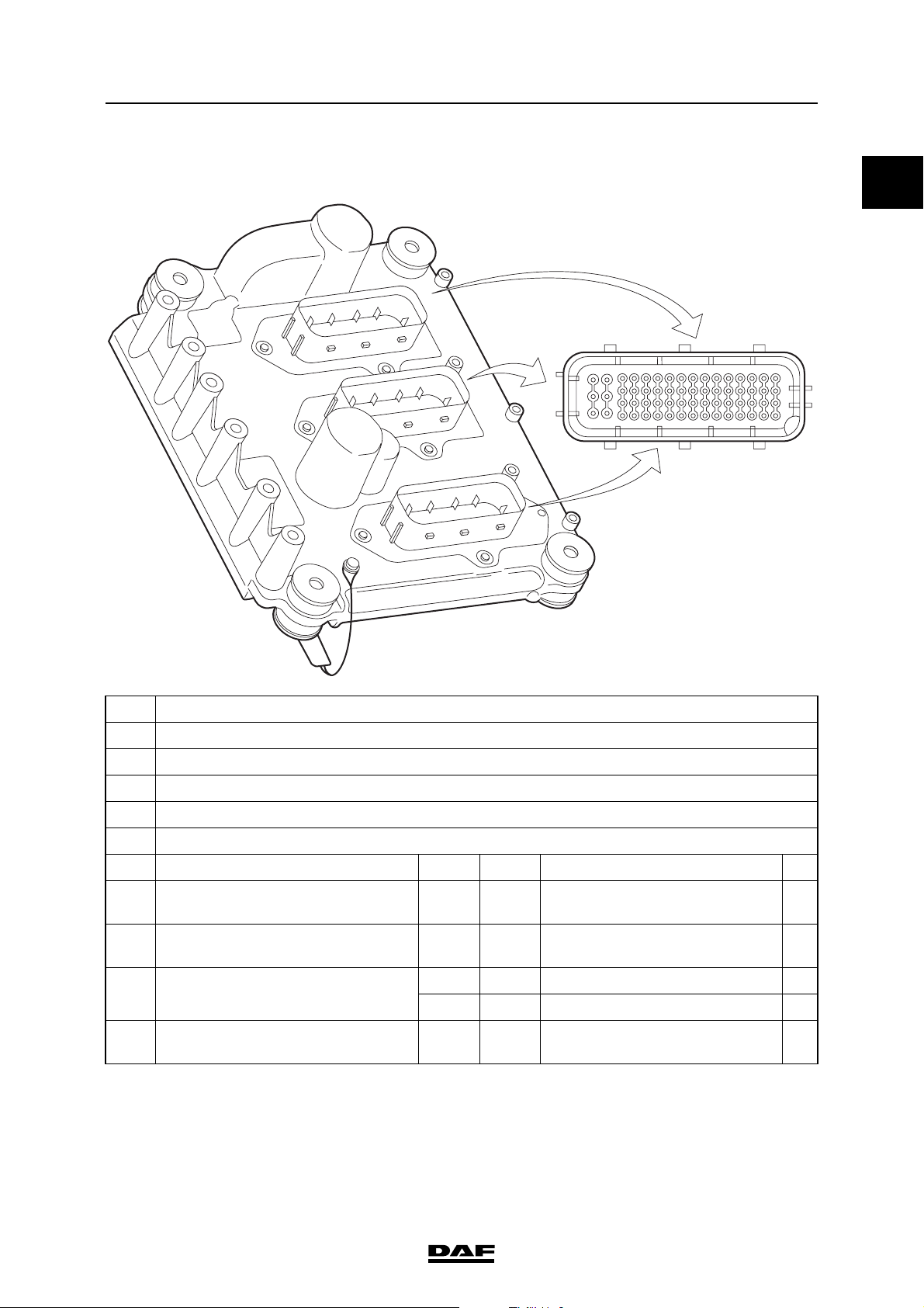
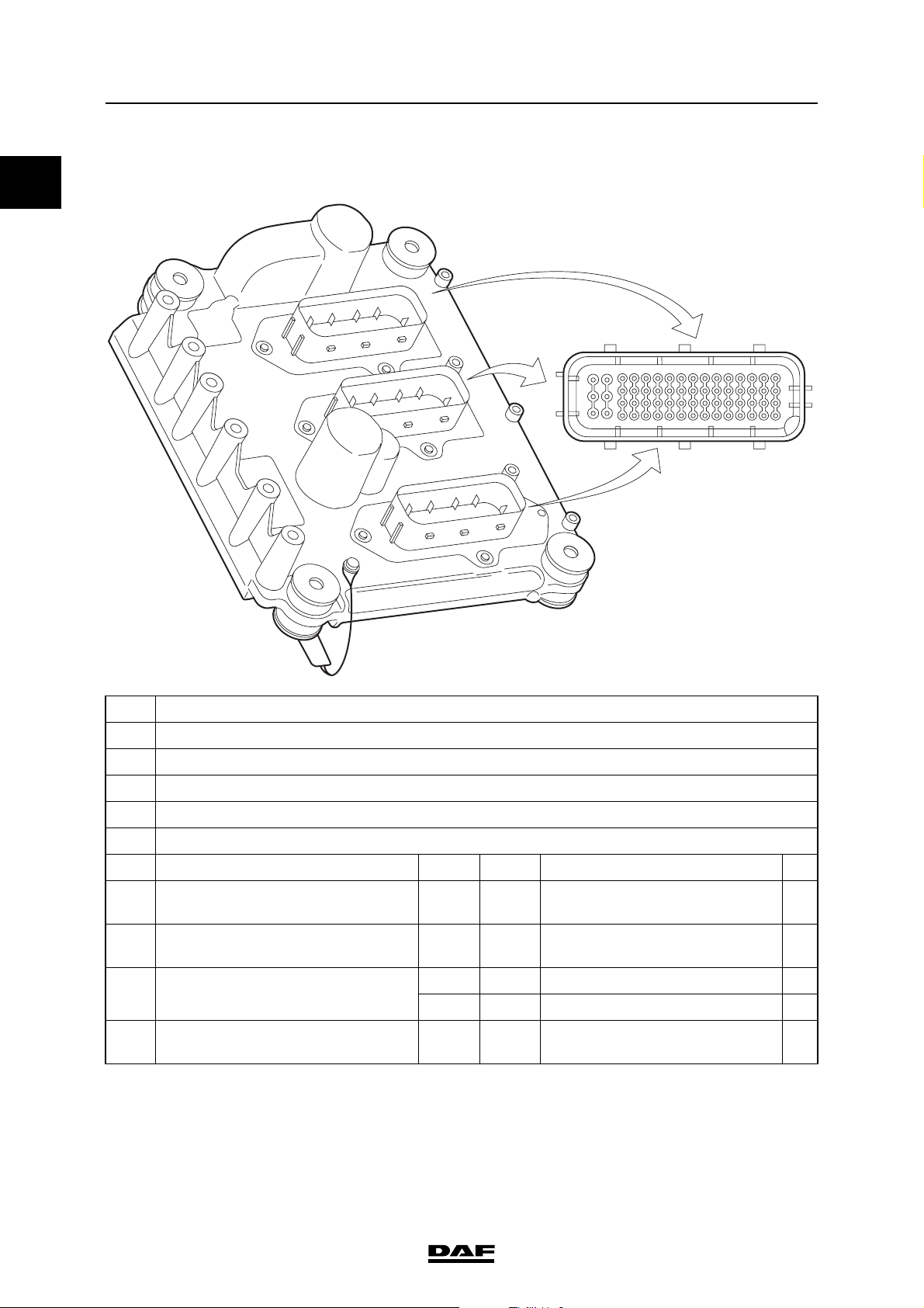
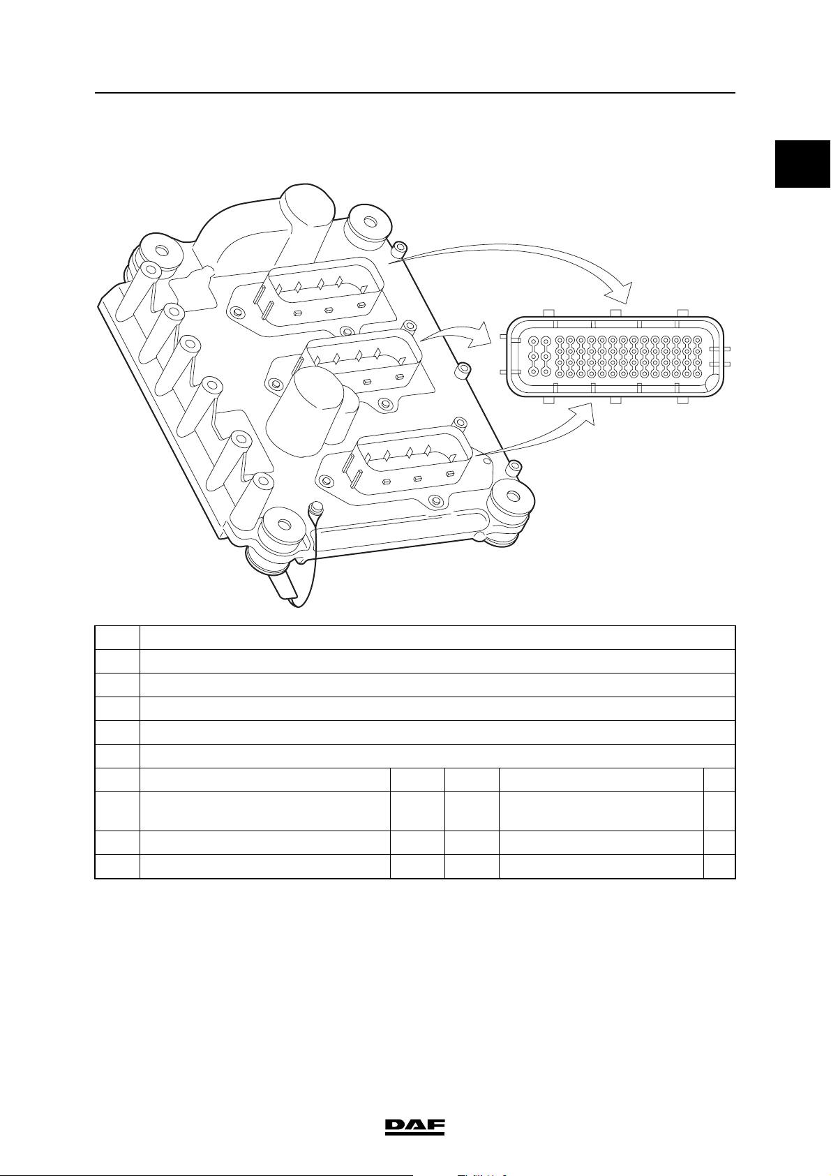
2.1 DMCI ELECTRONIC UNIT
The electronic unit is mounted on the cylinder
block using rubber insulating bushes (3). The
electronic unit has three 62-pin connectors. Input
signals from various sensors are continuously
processed and compared with data stored in
various maps (tables) in the electronic unit.
Actuators are energised on the basis of the
signals received and the maps.
The housing (1) of the electronic unit is directly
connected to the engine block by an earth cable
(2). This earth connection is required because of
internal components which protect against radio
waves from outside.
The electronic unit incorporates an atmospheric
pressure sensor and a temperature sensor.
There is an air vent (4) for the atmospheric
pressure sensor in the housing of the electronic
unit.
An identification sticker (5) is attached to the
electronic unit.
Description of components
1
4
1
5
3
2
i400785
The effect of atmospheric pressure on the
system:
- the quantity of fuel injected when driving at
high altitudes (low air pressure).
If atmospheric pressure is low (in mountainous
areas), the air is thinner. When the air is thinner it
has a low density. The electronic unit uses this
information to control the turbocharger pressure
and adjust the quantity of fuel to be injected.
The effect of the internal temperature sensor
on the system:
- none.
The internal temperature sensor measures the
temperature of the electronic unit. If the
temperature becomes too high, a fault code is
stored. The system does not take any further
action on the basis of this information.
Calibration
The performance of pump units and injectors may
differ slightly from one another as a result of small
production tolerances. These small production
differences are compensated for during
production by means of calibration in order to
optimise the engine output, exhaust gas
emissions and handling characteristics. A
calibration code is used to program the pump
units and injectors into the electronic unit
individually. The electronic unit modifies the
control of the pump units and injectors on the
basis of these calibration codes.
©
200528 2-1
Page 66

1
DMCI ENGINE MANAGEMENT SYSTEM
Description of components XF105 series
2.2 ACCELERATOR PEDAL SENSOR
1 Kick-down switch
2 Accelerator pedal sensor
D965
The accelerator pedal sensor (F672) is mounted
on the accelerator pedal. The sensor (2) consists
of a potentiometer and a switch.
Potentiometer
The output signal (B33) from the potentiometer is
a linear voltage that has a fixed relationship with
the position of the accelerator pedal and
therefore is determined by the driver. The
potentiometer signal is the basis for determining
the quantity of fuel to be injected. The
potentiometer has a supply voltage (B34) and an
earth (B37) via the electronic unit.
B34
B33 B37 B38 B41
4677
4679
4678
4166
4680
CABDF
Idling switch
Parallel to the potentiometer also the idling switch
is operated by depressing the accelerator pedal.
The idling switch is open in the no-load position
and is closed when the accelerator pedal is
operated. The switch is required for the
emergency function, when the potentiometer
signal is absent. This emergency function allows
the vehicle to be driven to a safe place or a
workshop if there is no potentiometer signal. One
side of the switch is connected to earth (B38) via
the electronic unit. The positive side (B41) is
connected to earth by means of the switch.
Kick-down switch
The kick-down switch (1) under the accelerator
pedal only acts to form a mechanical resistance
when the accelerator pedal is depressed. The
electronic unit detects the kick-down status
because the value of the output signal from the
potentiometer is higher than at full load. The kickdown switch is for instance used to temporarily
disengage variable vehicle speed limiting so that
an automatic/automated gearbox can shift down
(in order to accelerate).
F672
2
1
i400694
2-2
©
200528
Page 67

DMCI ENGINE MANAGEMENT SYSTEM
XF105 series
Effect of potentiometer output signal on the
system:
- the basis for determining the quantity of fuel
to be injected.
- engine brake disengaging/engaging
conditions
- disengaging conditions of Downhill Speed
Control
- CAN message accelerator pedal position,
via V-CAN1 (AS Tronic, AGC-A) and
V-CAN2 (EBS-2, VIC-2, builder module);
- CAN message kickdown position active, via
V-CAN1 (AS Tronic, AGC-A);
Effect of idling switch output signal on the
system:
- emergency function if the potentiometer is
not working.
- engine brake disengaging/engaging
conditions
- disengaging conditions of Downhill Speed
Control
- CAN message idling switch active, via
V-CAN1 (AS Tronic) and V-CAN2 (VIC-2,
ZF intarder EST-42, EBS-2, DIP-4, builder
module)
Description of components
1
©
200528 2-3
Page 68

1
DMCI ENGINE MANAGEMENT SYSTEM
Description of components XF105 series
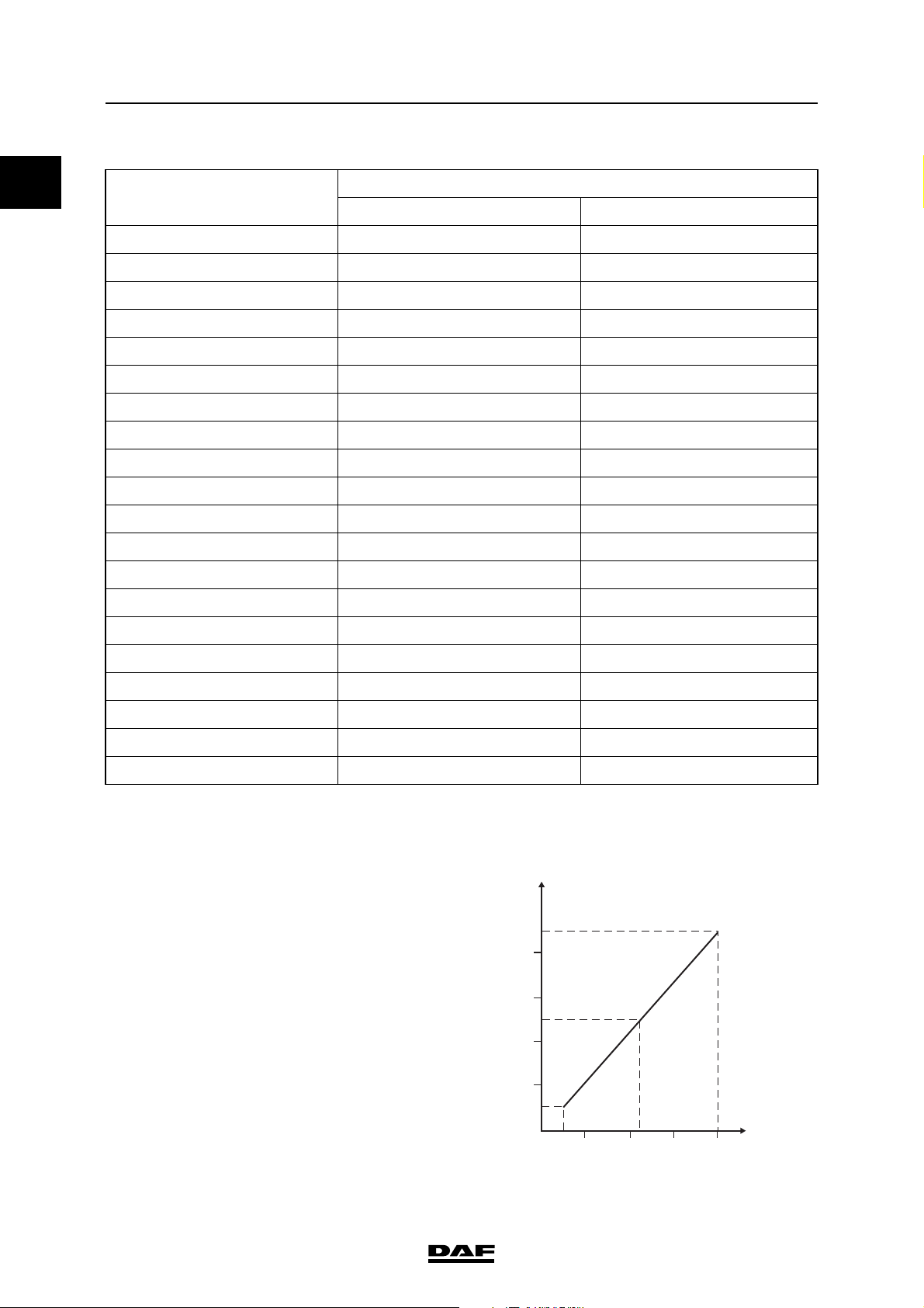
2.3 COOLANT TEMPERATURE SENSOR
The coolant temperature sensor emits a signal
that indicates the temperature of the coolant and
therefore indirectly the engine temperature. The
sensor used is of the NTC (negative temperature
coefficient) type. The higher the temperature, the
lower the resistance of the sensor.
Effect of output signal on the system:
- calculation of glowing time;
- calculation of the quantity of fuel to be
injected and the injection timing;
- calculation of actuation of the electronically
controlled fan clutch;
- limiting of engine torque when temperature is
too high;
- CAN message engine temperature, via
V-CAN2 to VIC-2 for display on the
instrument panel;
- limitation of the maximum engine speed
when the engine is cold.
i 400440
2.4 2nd COOLANT TEMPERATURE SENSOR
The 2nd coolant temperature sensor (F743) gives
a signal of the temperature of the coolant and
therefore indirectly of the engine at the level of
cylinder 6. The signal is compared by the
electronic unit (D965) to the signal from the
coolant sensor (F566) at the level of cylinder 1.
The sensor is of the NTC (Negative Temperature
Coefficient) type. The higher the temperature, the
lower the resistance of the sensor.
Effect of the signal on the system:
- Detection of a cooling problem resulting in
engine torque limitation
i401003
2-4
©
200528
Page 69

DMCI ENGINE MANAGEMENT SYSTEM
XF105 series
Description of components
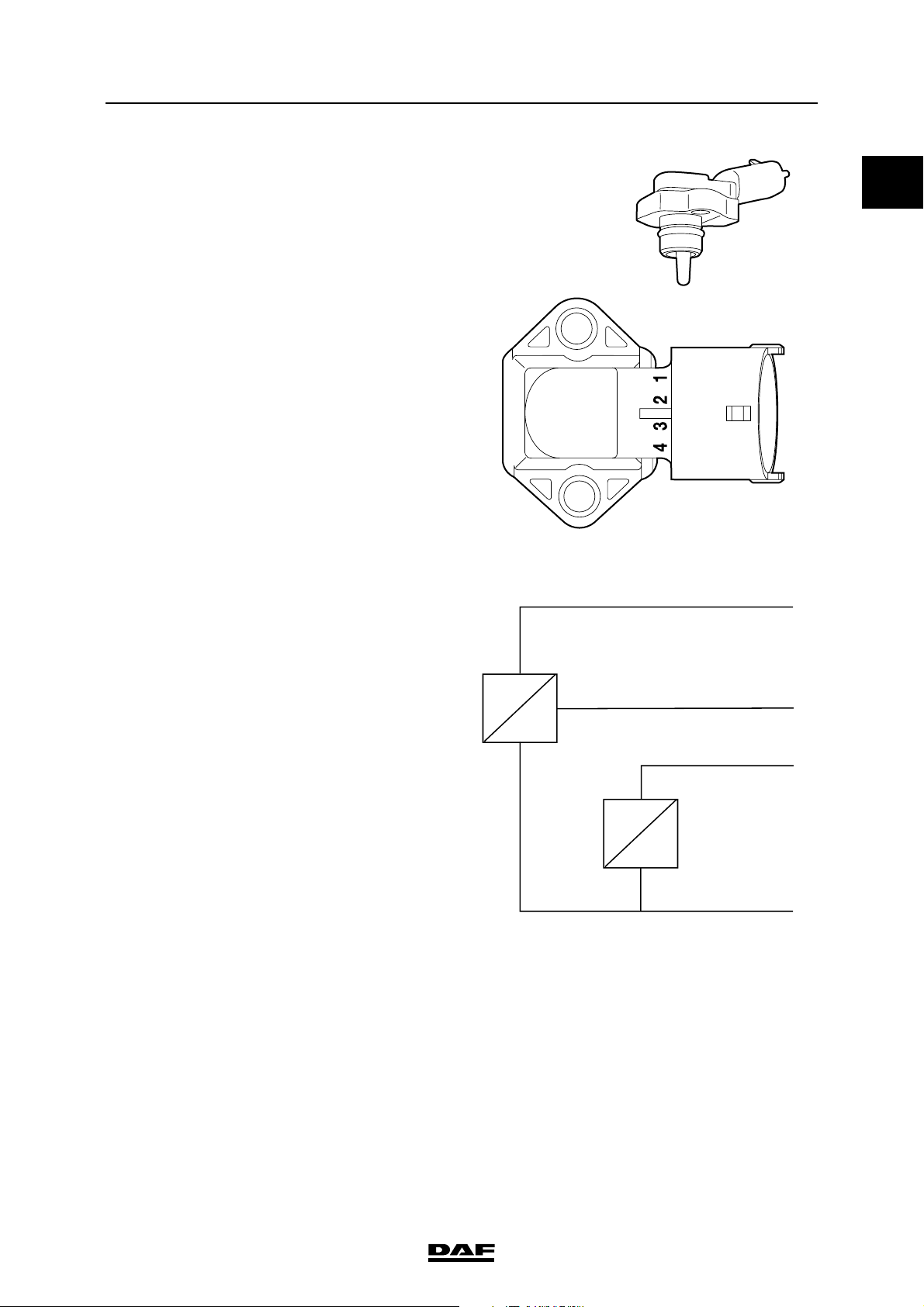
2.5 INLET AIR BOOST PRESSURE AND TEMPERATURE SENSOR
This is a combined sensor that measures the air
pressure in the inlet manifold and the
temperature of this air. The electronic unit uses
this data to calculate the quantity of air drawn in.
The quantity of intake air needs to be known in
order to calculate the quantity of injected fuel to
prevent smoke. The charge pressure is also in a
direct relationship to the turbocharger pressure
control. The waste gate valve is actuated
depending on this signal.
1
1 Air inlet pressure sensor, piezo-resistive
2 Electrical connection
3 Air inlet temperature sensor, NTC
4 Air inlet opening
5O-ring
6 Accommodation
The charge temperature sensor (3) used is of the
NTC (negative temperature coefficient) type. The
higher the temperature, the lower the resistance
of the sensor. The charge pressure sensor (1) is
a piezoresistive sensor. The inlet air is measured
via an opening (4) in the sensor. The higher the
pressure, the higher the voltage signal. The
sensor is sealed in the installation hole in the
cylinder head by an O-ring (5).
i 400441
1 2
6
5
4
3
i400742
©
200528 2-5
Page 70

DMCI ENGINE MANAGEMENT SYSTEM
Description of components XF105 series
The temperature signal is fed back to the
electronic unit via a connection (2).
A piezoresistive sensor requires a power
supply (3) and earth (1) to create a linear
voltage signal (4).
3
1
Effect of temperature signal on the system:
- calculation of glowing time;
- correction on the waste gate control;
- correction on the smoke limiting system.
Effect of pressure signal on the system:
- calculation for smoke limiting;
- calculation of the waste gate control;
- protection of turbocharger;
- CAN message to VIC for the charge boost
pressure display on the main display of
the DIP.
P
4
U
2
T
R
1
i400534
2-6
©
200528
Page 71

DMCI ENGINE MANAGEMENT SYSTEM
XF105 series
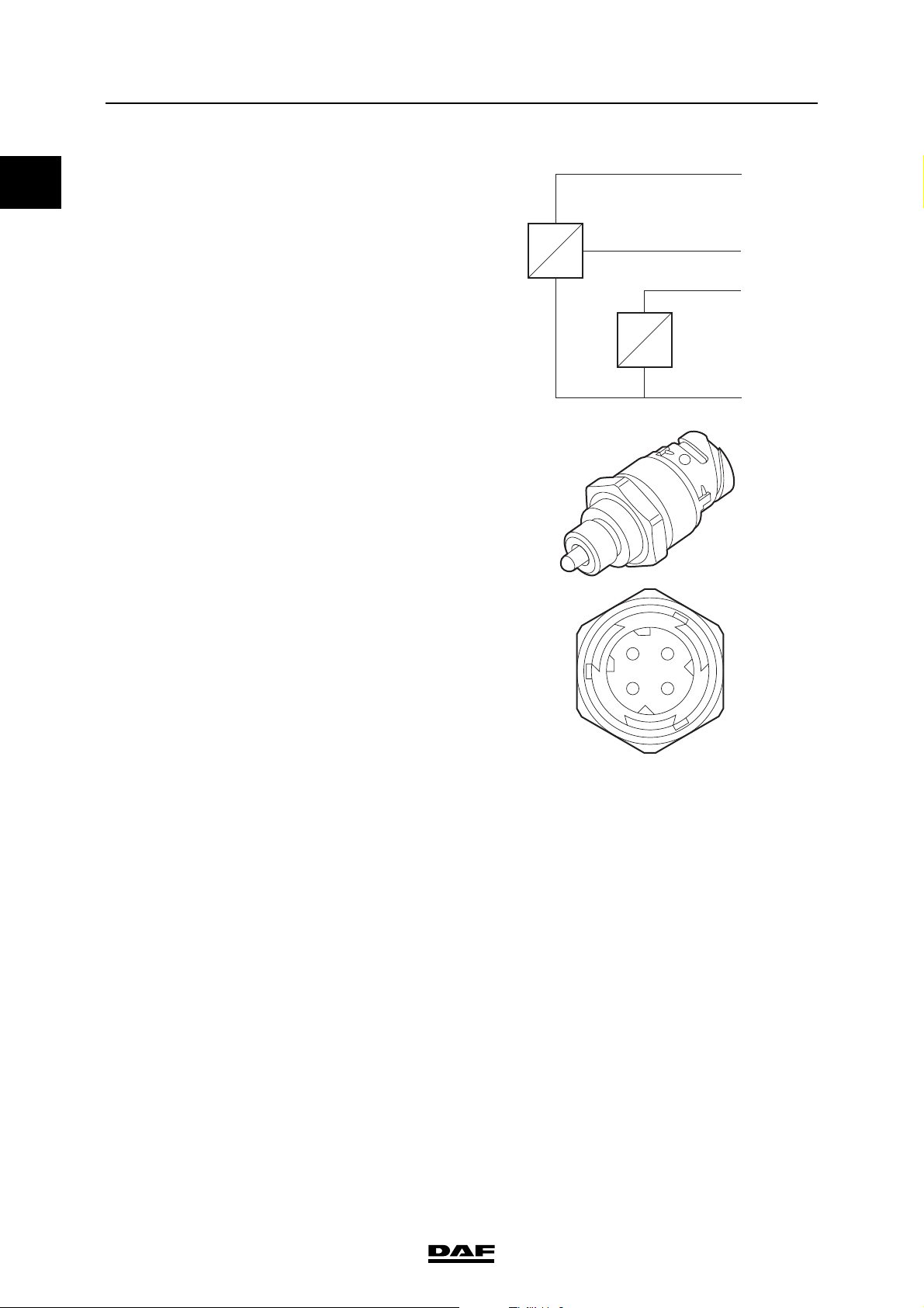
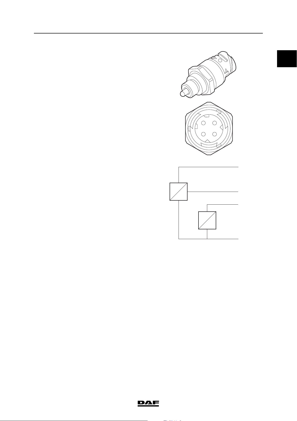
2.6 FUEL PRESSURE AND TEMPERATURE SENSOR
This is a combined sensor that measures the fuel
pressure in the fuel gallery and the temperature
of this fuel. The sensor is located in the middle of
the fuel gallery between the cylinder 3 pump unit
and the cylinder 4 pump unit. Because of this the
measured values for fuel pressure and
temperature are the most representative for the
whole fuel gallery.
The fuel temperature sensor is of the NTC
(negative temperature coefficient) type. The
higher the temperature, the lower the resistance.
The fuel pressure sensor is a Piëzo capacitive
sensor. The higher the pressure, the higher the
voltage signal.
The temperature signal is fed back to the
electronic unit via a connection (3).
A Piëzo capacitive sensor requires a power
supply (1) and earth (4) to create a linear voltage
signal (2).
P
Effect of temperature signal on the system:
- correction of quantity of fuel to be injected;
- calculation of glowing time;
U
Description of components
1
13
42
i400792
2
1
3
Effect of pressure signal on the system:
- enabling fuel pressure to be read on DAVIE;
T
R
4
i400791
©
200528 2-7
Page 72

1
DMCI ENGINE MANAGEMENT SYSTEM
Description of components XF105 series
2.7 ENGINE OIL PRESSURE AND TEMPERATURE SENSOR
This is a combined sensor that measures the
engine oil pressure in the cylinder block main
passage and the temperature of this oil.
The engine oil temperature sensor used is of the
NTC (negative temperature coefficient) type. The
higher the temperature, the lower the resistance
of the sensor. The engine oil pressure sensor is a
Piëzo capacitive sensor. The higher the pressure,
the higher the voltage signal. The engine oil
pressure is measured via an opening in the
sensor. The higher the pressure, the higher the
voltage signal.
13
42
i400792
The temperature signal is fed back to the
electronic unit via a connection (3). A piëzocapacitive sensor requires a power supply (1)
and earth (4) to create a linear voltage signal (2).
Effect of temperature signal on the system:
- none.
Effect of pressure signal on the system:
- CAN message to VIC to actuate oil pressure
indicator light and warning on the DIP main
display when engine oil pressure is too low.
P
2
1
U
3
T
R
4
i400791
2-8
©
200528
Page 73

DMCI ENGINE MANAGEMENT SYSTEM
XF105 series
2.8 CRANKSHAFT SENSOR
1 Electrical connection, earth
2 Electrical connection, signal
3 Electrical connection, shield
A Crankshaft sensor
B Flywheel housing
C Magnet
D Metal core
ECoil
F Flywheel
G Hole pattern
The crankshaft sensor (F552) registers engine
speed and is used to determine the injection
timing. The crankshaft sensor is responsible,
together with the camshaft sensor, for
synchronisation when starting the engine. If there
is no camshaft signal, the crankshaft signal is
used for cylinder detection.
The crankshaft sensor (A) is mounted on the
flywheel housing (B). It is an inductive sensor and
consists of a magnet (C), a metal core (D) and a
coil (E). Inductive means that the sensor can
generate an alternating voltage signal
independently by means of a changing magnetic
field. The pattern of holes in the flywheel (F)
means that the sensor can generate a specific
alternating signal. The pattern consists of 3
segments each with 18 holes and an area with
2 holes missing (G). Each segment is used for
calculations on two specific cylinders (1/6, 2/5
and 3/4).
The sensor has 3 connections. Pins 1 and 2 are
responsible for the signal. Pin 2 is the signal
connection and pin 1 is the earth connection. Pin
3 is connected to the shield around the signal
wires and to the earth connection (pin 1). This
prevents the engine speed signal being affected
by signals from outside.
Description of components
1
2
A
3
B
1
S
N
C
D
E
1
F
18
G
I400731
©
200528 2-9
Page 74

1
DMCI ENGINE MANAGEMENT SYSTEM
Description of components XF105 series
The most powerful changes in the magnetic field
of the sensor take place when the pattern of holes
(1) in the flywheel changes from a hole to a tooth
and vice versa. A sine-wave alternating voltage
(2) is generated as a result of this changing
magnetic field. As a hole approaches, the
crankshaft sensor signal must be at the maximum
positive value and then drop to the maximum
negative value as the end of the hole
approaches. This is determined by the sensor
connections to the electronic unit! The electronic
unit converts this sine-wave alternating voltage
signal to a digital signal (3) which it uses to carry
out calculations.
1
2
3
E500606
ab
c
1
2
2-10
©
200528
I400732
Page 75

DMCI ENGINE MANAGEMENT SYSTEM
XF105 series
Sine-wave signals (2) can be measured using an
oscilloscope with the engine running using the
pattern of holes in the flywheel (1). Each hole in a
segment (b) generates a sine-wave pulse. When
the area with the two holes missing (a and c) goes
under the crankshaft sensor, the pulse pattern is
interrupted. This enables the sensor to detect the
end of the segment.
Effect of output signal on the system:
- synchronisation during starting;
- injection timing calculation;
- registration of engine speed;
- cylinder detection if there is no camshaft
signal.
- CAN message engine speed to other vehicle
systems via V-CAN1 (AS Tronic, EAS) and
V-CAN2 (VIC-2, ZF intarder EST-42, ABS-D,
EBS-2, DIP-4, ECAS-4, builder module)
- output signal engine speed (EMAS, cab
lead-through connector).
Description of components
1
©
200528 2-11
Page 76

1
DMCI ENGINE MANAGEMENT SYSTEM
Description of components XF105 series
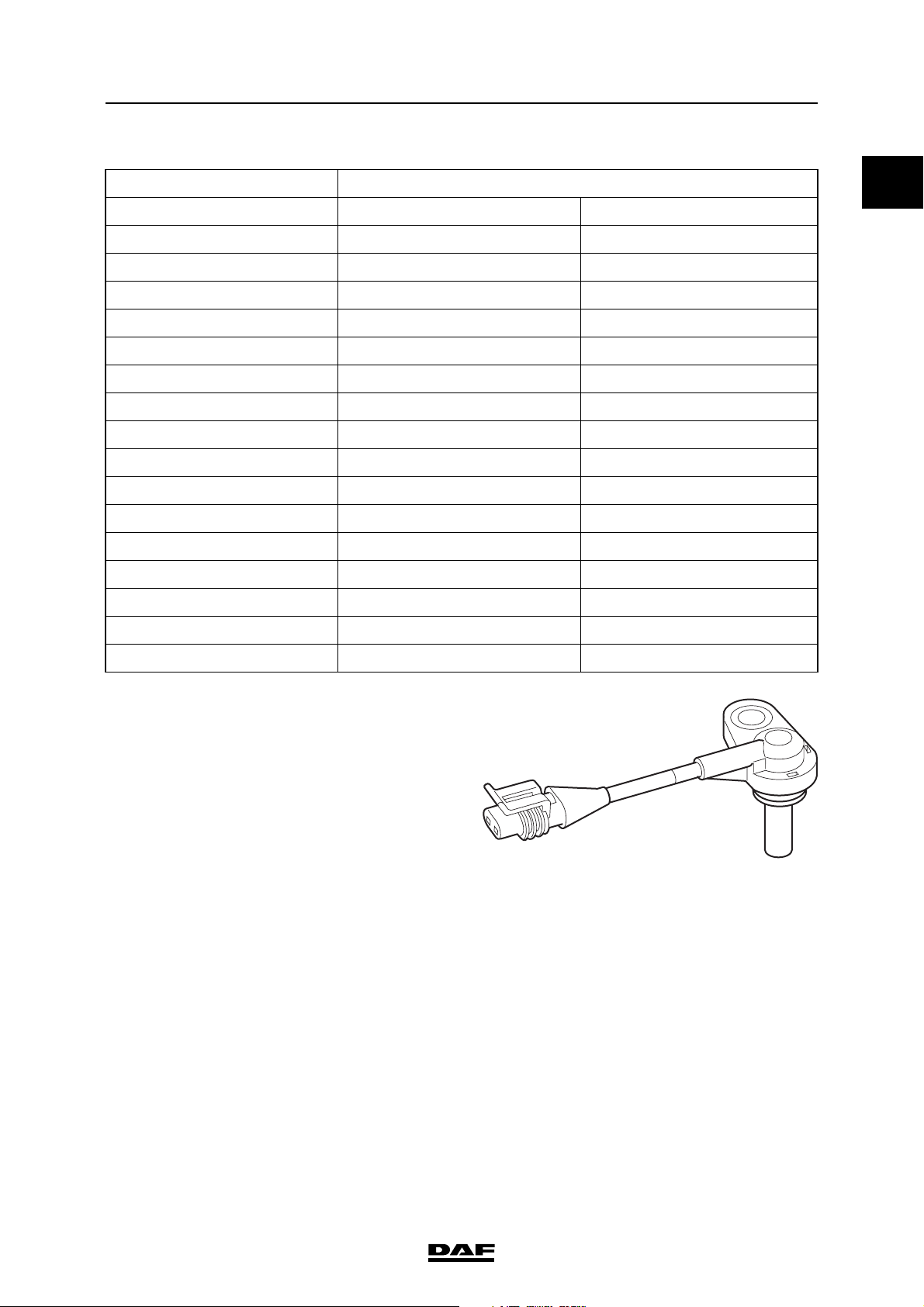
2.9 CAMSHAFT SENSOR
The camshaft sensor (F558) is responsible,
together with the crankshaft sensor, for
synchronisation when starting the engine. The
signal also provides the information relating to
cylinder detection. If the crankshaft sensor (F552)
is defective the camshaft signal acts as a reserve
signal for registering the engine speed and
determining the correct injection timing.
1 Electrical connection, signal
2 Electrical connection, earth
3 Electrical connection, shield
A Camshaft sensor
B Flywheel housing
C Magnet
D Metal core
ECoil
F Pulse wheel
The camshaft sensor (A) is mounted on the
flywheel housing (B). It is an inductive sensor and
consists of a magnet (C), a metal core (D) and a
coil (E). Inductive means that the sensor can
generate an alternating voltage signal
independently by means of a changing magnetic
field. The sensor can generate a specific
alternating signal by means of a tooth pattern on
the pulse wheel (F). The sensor has 3
connections. Pins 1 and 2 are responsible for the
signal. Pin 1 is the signal connection and pin 2 is
the earth connection. Pin 3 is connected to the
shield around the signal wires and to the earth
connection (pin 2). This prevents the signal being
affected by signals from outside.
1
S
A B
S
N
5
4
1
2
3
C
D
E
3
F
6
2
I400761
2-12
©
200528
Page 77

DMCI ENGINE MANAGEMENT SYSTEM
XF105 series
The most powerful changes in the magnetic field
of the sensor take place when the tooth pattern
(1) on the pulse wheel changes from a tooth to a
hole and vice versa. A sine-wave alternating
voltage (2) is generated as a result of this
changing magnetic field. As a tooth approaches,
the camshaft sensor signal must be at the
maximum positive value and then drop to the
maximum negative value as the end of the tooth
approaches. This is determined by the sensor
connections to the electronic unit! The electronic
unit converts this sine-wave alternating voltage
signal to a digital signal (3) which it uses to carry
out calculations.
624s153
Description of components
1
1
2
3
i400839
a
b
0
I400762
©
200528 2-13
Page 78

1
DMCI ENGINE MANAGEMENT SYSTEM
Description of components XF105 series
Sine-wave signals (2) can be measured using an
oscilloscope with the engine running using the
tooth pattern on the pulse wheel (1). Each tooth,
and therefore pulse, corresponds to a specific
cylinder. The additional tooth before the
cylinder -1 tooth is the synchronisation tooth (S).
The pulse this generates is required to realise the
synchronisation procedure together with the
crankshaft sensor signal.
Effect of output signal on the system:
- synchronisation during starting;
- cylinder detection;
- calculation of injection timing if crankshaft
sensor is defective;
- registration of engine speed if crankshaft
sensor is defective.
- CAN message engine speed to other vehicle
systems if the crank shaft sensor is faulty via
V-CAN1 (AS Tronic, EAS) and V-CAN2
(VIC-2, ZF intarder EST-42, ABS-D, EBS-2,
DIP-4, ECAS-4, builder module)
- output signal engine speed if crankshaft
sensor is faulty (EMAS, cab lead-through
connector).
2-14
©
200528
Page 79

DMCI ENGINE MANAGEMENT SYSTEM
XF105 series
2.10 WASTE GATE VALVE
1 Electrical connection
2 Internal electronics
3Coil
4Core
5valve
6 Air connection, supply(1)
7Vent (3)
8Piston
9 Air connection, waste gate (2) control
pressure
10 Accommodation
11 Internal pressure sensor
The waste gate valve controls opening and
closing of the waste gate on the turbocharger.
The waste gate valve air supply (6) comes
directly from the air supply unit circuit 4 (approx.
10 bar) and is adjusted in the valve to a control
pressure (9) for the diaphragm housing of the
waste gate. The waste gate valve checks the
output pressure using an internal pressure
sensor (11). The signal issued by the internal
pressure sensor is compared by the internal
electronics (2) to the signal from the electronic
unit. The internal electronics energises the coil
(3) with a duty cycle (PWM) signal. If the required
pressure differs from the actual pressure, the
internal electronics modifies the duty cycle.
11
10
Description of components
1
2
U
I
1
3
U
P
4
5
9
8
6
7
i400741
Rest position/bleeding
In the rest position or during bleeding, the coil (3)
is not energised. The piston (8) and valve (5) are
pushed up by the force of the spring. This also
pushes up the metal core (4). The outlet (9) is
now connected to the air bleed vent (7).
U
I
U
P
i400745
©
200528 2-15
Page 80

1
DMCI ENGINE MANAGEMENT SYSTEM
Description of components XF105 series
Constant pressure
When the coil (3) is energised, the metal core (4)
is pushed down. The valve (5) closes off the
opening to the air bleed vent on the piston (8).
The pressure present in the outlet (9) now stays
constant.
Pressure increase
If the coil (3) remains activated for longer, the
valve (5) will push the piston (8) further down and
the air supply opening (6) to the outlet (9) is
released. This increases the output pressure.
U
P
U
I
i400746
U
I
U
P
i400747
2-16
©
200528
Page 81

DMCI ENGINE MANAGEMENT SYSTEM
XF105 series
2.11 PUMP UNIT
General
A. Fuel gallery opening
B. Return opening
C. Injector inlet connection
1. Lid
2. Coil
3. Pump unit housing
4. Spring
5. Plunger
6. Roller tappet
7. Delivery valve
8. Electrical connection
The pump unit supplies fuel to the injector. The
pump unit consists of a metal housing (3) in
which an electrical coil (2) opens a valve (1). In
the rest position, the valve (1) is pushed up by a
spring (4). The electrical connection (8) is
screwed onto the outside of the pump unit. The
roller tappet (6) rotates around the camshaft and
actuates the plunger (5), which builds up the fuel
pressure. The fuel enters the pump unit via the
fuel gallery opening (A). This opening goes into
the fuel supply gallery in the engine block. The
fuel leaves the pump unit in the direction of the
injector via a delivery valve (7). The fuel pipe is
fitted to the injector supply connection (C). Leakoff/lubricating fuel from the plunger is fed back to
the return gallery in the engine block via the
return opening (B).
1
2
3
4
A
5
Description of components
1
C
7
8
B
6
i4 00 714
©
200528 2-17
Page 82

1
DMCI ENGINE MANAGEMENT SYSTEM
Description of components XF105 series
Electrical control
The pump unit is activated with a voltage of
approximately 50V. This voltage is the discharge
from a capacitor in the DMCI electronic unit. The
current increases rapidly because of this
relatively high voltage. As a result, the valve in the
pump unit opens quickly. This is the pick-up
phase. If the current were not limited, it would
become too high and damage the coil in the pump
unit. The increase in the current is limited by
switching to pulsating control of approximately
24V after discharging the capacitor. This is the
withstand phase. The current now remains high
enough to hold the valve open. The length of the
pick-up phase stays practically the same under
all circumstances. The length of the withstand
phase will vary depending on the calculations
carried out by the electronic unit. When the pump
unit is deactivated a negative induction peak is
created by switching off the current through the
pump unit coil.
Operation
The fuel is supplied to the pump unit via the
gallery in the engine block flowing towards the
delivery chamber above the plunger. The delivery
chamber now fills.
U (V)
60
40
20
0
i400845
2-18
i4 00 715
©
200528
Page 83

DMCI ENGINE MANAGEMENT SYSTEM
XF105 series
The pressure does not build up immediately
when the plunger is pushed up by the camshaft.
The fuel can still flow back to the fuel gallery via
the supply opening.
Description of components
1
i4 00 716
©
200528 2-19
Page 84

1
DMCI ENGINE MANAGEMENT SYSTEM
Description of components XF105 series
When the coil is activated, the valve is pulled
down and the opening to the fuel gallery closes.
Pressure only starts to be built up by the plunger
now. The fuel cannot flow back to the gallery and
now has to flow towards the injector outlet via the
delivery valve. Fuel is now supplied to the
injector.
i4 00 717
2-20
©
200528
Page 85

DMCI ENGINE MANAGEMENT SYSTEM
XF105 series
When the coil is deactivated by the electronic
unit, the valve is pushed up again by the spring
and the opening to the fuel gallery is released
again. This stops the supply of fuel to the injector.
Description of components
1
i4 00 715
©
200528 2-21
Page 86

1
FMFM
30209
DMCI ENGINE MANAGEMENT SYSTEM
Description of components XF105 series
Every pump unit is calibrated after production to
compensate for any inaccuracies/differences in
production. There is a 4-letter calibration code on
the housing of the electrical connections. The
code must be programmed into the electronic unit
so that the unit can optimise controls for fuel
injection. If the pump unit is replaced or moved,
the calibration code must be programmed into the
electronic unit again using DAVIE XD.
1621297
SN 03030209
00000FMFM
i400771
2-22
©
200528
Page 87

DMCI ENGINE MANAGEMENT SYSTEM
XF105 series
2.12 INJECTOR
General
A. Fuel supply
B. Return opening
1. Injector body
2. O-ring
3. O-ring
4. Nozzle holder
5. Washer
6. Nozzle
7. Electrical connection
8. Bar filter
9. Spring
10. Coil
11. Valve
12. Plunger
13. Plunger spring
14. Injector needle
The pump unit supplies fuel to the injector. The
injector consists essentially of two parts. The top
part is a metal housing (1), to which the electrical
connector (7) is attached. The coil (10) and spring
(9) that open and close the valve (11) are also in
the housing. The bottom part bears the closest
resemblance to a conventional injector. The valve
(11) and its guide are in this part, the nozzle
holder (4). Below this are the plunger (12) and
spring (13) and finally the nozzle (6), with the
injector needle (14) inside. The copper washer
(5) is under the nozzle holder.
The fuel enters the injector via the supply (A), in
which the bar filter (8) is pressed. The return fuel
leaves the injector via the opening (B) and flows
into the cylinder head return duct.
Description of components
1
7
1
2
A
8
3
B
4
9
10
11
12
13
5
14
6
i400721
©
200528 2-23
Page 88

1
DMCI ENGINE MANAGEMENT SYSTEM
Description of components XF105 series
Electrical control
The injector is activated with a voltage of
approximately 50V. This voltage is the discharge
from a capacitor in the DMCI electronic unit. The
current increases rapidly because of this
relatively high voltage. As a result, the valve in the
injector opens quickly. This is the pick-up phase.
If the current were not limited, it would become
too high and damage the coil in the injector. The
increase in the current is limited by switching to
pulsating control of approximately 24V after
discharging the capacitor. This is the withstand
phase. The current now remains high enough to
hold the valve open. The length of the pick-up
phase stays practically the same under all
circumstances. The length of the withstand phase
will vary depending on the calculations carried
out by the electronic unit. When the pump unit is
deactivated a negative induction peak is created
by switching off the current through the injector
coil.
Operation
In the rest position, the valve is pushed down by
the spring above the valve. The opening to the
return is now closed.
U (V)
60
40
20
0
i400846
2-24
i4 00 722
©
200528
Page 89

DMCI ENGINE MANAGEMENT SYSTEM
XF105 series
Even though fuel is now being supplied to the
injector, this does not mean that it immediately
starts injecting. The same fuel pressure that must
lift the injector needle also pushes down the
plunger - along with the plunger spring. The
injector needle cannot yet be lifted.
Description of components
1
When the coil is activated by the electronic unit,
the valve is pulled in against the pressure of the
spring and the opening to the return is released.
As a result, the pressure above the plunger
decreases. The fuel pressure under the injector
needle now overcomes the pressure of the spring
above the plunger. The injector needle is lifted
and fuel is injected.
To stop injection, the fuel supply pressure to the
injector is decreased by deactivating the pump
unit. The injector is only deactivated once the fuel
pressure is low enough. This is to allow the
plunger spring to close the injector needle
quickly.
i4 00 723
©
200528 2-25
Page 90

1
DMCI ENGINE MANAGEMENT SYSTEM
Description of components XF105 series
Every injector is calibrated during production to
compensate for any inaccuracies/differences in
production. There is a 6-letter calibration code on
the housing of the electrical connections. The
code must be programmed into the electronic unit
so that the unit can optimise controls for fuel
injection. As a result, the electronic unit can
ensure that the injection timing and the quantity of
fuel injected do not differ. If the injector is
replaced or moved, the calibration code must
be programmed into the electronic unit using
DAVIE XD.
i400772
2-26
©
200528
Page 91

DMCI ENGINE MANAGEMENT SYSTEM
XF105 series
2.13 ELECTRONICALLY CONTROLLED FAN CLUTCH
1Stator
2 lid
3 Rotor
4Coil
5 Drive shaft
6 Supply chamber
7 Working area
An electronically controlled fan clutch is used for
accurate control of the fan speed.
The electronically controlled fan clutch checks
and controls the fan speed to ensure that the flow
of cooling air through the cooling system is
sufficient to keep the coolant temperature and/or
inlet air temperature within certain limits.
The coil (4) fitted to the drive shaft (5) with
bearings generates a magnetic field. The duty
cycle to the coil (4) will be modified depending on
the variables stated above. This will cause
changes in the magnetic field and the valve (2)
will be attracted either more or less.
Description of components
1
2
3
4
1
Control of the fan clutch depends on various
factors:
- coolant temperature
- the inlet air temperature
- vehicle speed
- engine speed
-fan speed
- intarder activation
- internal slip of the fan clutch (slip heat
protection)
The fan clutch consists of a stator (1) and the
rotor (3), which is fixed to the drive shaft (5). It
also includes the supply chamber (6) for the
silicone fluid.
The working area is located between the
stator (1) and the rotor (3). The fan is fitted to
the stator (1) and rotates freely around the drive
shaft (5).
The speed of the fan is sensed by an internal Hall
sensor and a pulse disc.
This sensor sends a signal to the electronic unit
DMCI. The electronic unit uses this signal to
check the internal slip of the fan and the response
to controls.
5
6
7
i401012
©
200528 2-27
Page 92

1
DMCI ENGINE MANAGEMENT SYSTEM
Description of components XF105 series
Operation
Fan clutch not actuated
The lid (2) is now in the original position. The filler
opening is now released and the return opening
is closed. The quantity of silicon fluid through the
working area (7) between the stator (1) and the
rotor (3) increases because of this. The friction in
the working area between the stator (1) and the
rotor (3) will increase and the difference in
rotating speed (slip) between the stator (1) and
the rotor (3) will decrease. The fan speed is
increased because of this. The fan speed will
approach or exceed the engine speed depending
on the transmission between the crankshaft and
the fan drive.
Note:
This therefore means that in the event of the
failure of the actuation of the fan clutch the fan will
turn at maximum speed.
Not actuated
1
2
3
4
5
6
7
i401012
2-28
©
200528
Page 93

DMCI ENGINE MANAGEMENT SYSTEM
XF105 series
Fan clutch actuated
If the coil (4) is actuated by way of a duty-cycle
then the lid (2) will be attracted by the magnetism
created. The filler opening is then closed by the
lid (2) and at the same time the return opening is
opened up. The silicon fluid now flows from the
working area (7) between the stator (1) and the
rotor (3) to the supply chamber (6). Less silicon
fluid in the working area means more slip
between the stator (1) and the rotor (3). The fan
speed will decrease.
Note:
Duty cycle high means decreasing fan speed.
Duty cycle low means increasing fan speed.
Actuated
Description of components
1
2
3
4
1
5
6
7
i401013
©
200528 2-29
Page 94

1
DMCI ENGINE MANAGEMENT SYSTEM
Description of components XF105 series
2-30
©
200528
Page 95

DMCI ENGINE MANAGEMENT SYSTEM
XF105 series
Control functions
3. CONTROL FUNCTIONS
3.1 SYSTEM STATUS
When carrying out calculations, the electronic
unit always starts with a specific engine "status".
This status is a specific operating mode of the
engine. Controls are used or modified depending
on the status.
System status Description
On (STATIONARY) The ignition is switched on, the engine has not yet
started and is not running.
Starting (CRANKING) The engine is started.
Idling (IDLING) The engine is running at idling speed.
Engine running (RUNNING) The engine is running at speeds higher than idling
speed.
Cruise (CRUISE) The engine is running in the cruise control function,
or a control that adjusts the injection controls to
keep the vehicle speed constant.
1
PTO (PTO) The engine is running in the engine speed control,
or a control that keeps the engine speed constant
for driving power take off devices.
Overrevving (OVERSPEEDING) The engine is running with more rpm than normal
which may cause mechanical damage.
Off (POWER DOWN) The engine is switched off and is not running.
To
The electronic unit detects whether the vehicle
ignition is switched on via connection point B44.
This status remains active as long as no speed
signal is received.
Starting
Starting is detected via the engine speed signal.
The speed must be higher than a specific value,
but lower than the engine speed when idling.
Idling
The electronic unit detects this status by the
engine speed. The speed depends on the
different operating conditions (e.g. coolant
temperature).
Engine running
The engine speed is higher than a specific value.
©
200528 3-1
Page 96

DMCI ENGINE MANAGEMENT SYSTEM
Control functions XF105 series
Cruise
If a voltage signal is received on pin B20 or B16,
the electronic unit detects that the cruise control
switch has been operated. There must also be a
speed signal of 30 km/h present.
1
PTO
The PTO status is made known via a CAN
message via V-CAN1 from VIC-2. The "RES"
switch on the steering column switch / steering
wheel switch must also be operated so that DMCI
receives a CAN message from VIC-2 via V-CAN.
Overrevving
This status is detected when the engine speed is
higher than a specific value.
Off
Voltage is removed from pin B44. The electronic
unit detects that the ignition has been switched
off.
3-2
©
200528
Page 97

DMCI ENGINE MANAGEMENT SYSTEM
XF105 series
3.2 CAN CONTROLS
The DMCI engine management system
communicates via V-CAN1 and V-CAN2 with
various vehicle systems. DMCI is equipped with a
terminating resistor for V-CAN1 and V-CAN2.
V-CAN1 V-CAN2
VIC-2 VIC-2
EAS DIP-4
DMCI
Vehicle
CAN2-low
Vehicle
CAN2-high
CAN2 low
CAN2 high
B53
B45
R R
D965
Control functions
CAN1-low
B42
B46
B50
B54
Vehicle
Vehicle
CAN1-high
CAN1 low
CAN1 high
B35
B27
1
i400994
AS Tronic BBM
Immobiliser MTCO / DTCO
The DMCI electronic unit receives relevant
information from other electronic units and sends
information to these electronic units in its turn.
Communication with DAVIE XD takes place via
the D-CAN to VIC-2 and via VIC-2 and V-CAN1
again to DMCI.
A number of important CAN messages are shown
below.
ZF retarder EST-42
ABS-D
EBS-2
ECAS-4
©
200528 3-3
Page 98

1
DMCI ENGINE MANAGEMENT SYSTEM
Control functions XF105 series
Received CAN messages:
- request to activate the PTO/engine speed
control via application connector (BBM)
- immobiliser identification code to release fuel
supply (immobiliser)
- activation of ABS (EBS-2/ABS-D)
- activation of ASR (EBS-2/ABS-D)
- activation of ZF intarder (EST-42)
- vehicle speed signal (MTCO/DTCO)
- activation of cruise control (VIC-2)
- activation of PTO/engine speed control via
steering column switch (VIC-2)
Sent CAN messages:
- red and yellow fault messages (VIC-2)
- coolant temperature (VIC-2)
- engine speed (DIP-4, EAS, EBS-2, etc.)
- engine torque (EAS, EBS-2, AS Tronic)
- inlet air boost pressure (VIC-2)
- engine oil pressure (VIC-2)
- accelerator pedal position (ZF-intarder)
- engine brake activation (AS Tronic)
- activation of parking brake (VIC-2)
- status of variable vehicle speed limiting
(VIC-2)
- status of vehicle speed limiting for special
applications (VIC-2)
- fuel consumption (VIC-2)
3-4
©
200528
Page 99

DMCI ENGINE MANAGEMENT SYSTEM
XF105 series
3.3 PRE-GLOWING AND AFTER-GLOWING
The purpose of the glowing system is to warm up
the inlet air so that the engine starts up more
easily and so that the engine runs more smoothly
if the outside temperature is low. During preglowing, the inlet air is heated before the engine
starts. Glowing can also take place while the
engine is starting. After-glowing takes place when
the engine is running. Pre-glowing and glowing
when starting mean that the engine starts
smoothly. Glowing when starting and afterglowing reduce emissions (white smoke) in cold
conditions.
Depending on the number of input signals, the
electronic unit determines whether pre-glowing
and possibly after-glowing are necessary. If the
ignition is switched on then the electronic unit
compares the following temperatures:
- coolant temperature (F566),
- inlet air temperature (F649),
- fuel temperature (F713).
E184
(10A)
supply
C60
A42
supply
C61
A45
868587
supply
C62
A41
kl. 30 kl. 30
E392
(100A)
G014
Glow element
30
relay
E112
(5A)
engine
ground
C32
C39
A46
B314
Glow
element
C25
C26
G126
Main
relay
D965
Control functions
E118
(15A)
supply
C60
87a
supply
C61
87 86
supply
C62
A34
8530
B2
Vehicle
A27
CAN2
A28
low
CAN2 low
B53
A30
Vehicle
CAN2
high
CAN2 high
B45
Vehicle
CAN1
A49
low
CAN1 low
B35
A50
Vehicle
CAN1
high
CAN1 high
B27
A60
1
If one of these three temperatures is lower than a
certain programmed temperature then the
electronic unit will decide to activate the glow plug
relay. De laagste temperatuur van deze drie
bepaalt de tijdsduur van het voorgloeien.
Voorgloeien zal altijd gevolgd worden door
gloeien tijdens starten.
After-glowing is also determined by the lowest of
the three temperature signals (coolant, inlet air
and fuel). Glowing during starting and afterglowing prevents the emission of white smoke.
The electronic unit provides a glow plug relay
(G014) with current via pin C60,C61 and C62.
The glow relay (G014) is activated when the
electronic unit switches the relay to earth via pin
C32. If the glow plug relay is activated then the
glow element (B341) is provided with current via
the fuse (E392). At the same time the electronic
unit receives a current at pin C39. The electronic
unit can determine via this input whether the
glowing system is active, remains active when
not wanted or can not be activated. The
electronic unit then sends a CAN message to
VIC-2 to control the glow indication on DIP 4 or a
warning on the main display.
signal3signal
supply 5V
12
PUT
fuel
pres.
F713
R
fuel
temp.
ground
4
signal
1
T
coolant
temp.
F566
R
ground
2
signal
21
TRP
inlet
temp.
ground
F649
signal
supply 5V
34
U
boost
pres.
signal
return
21
N
crankshaft
speed
F552
shield
3
i400992
©
200528 3-5
Page 100

1
DMCI ENGINE MANAGEMENT SYSTEM
Control functions XF105 series
Conditions for activating the pre-glowing
function:
1. Battery voltage must be higher than a
specific value and
2. one of the three temperatures(coolant, inlet
air or fuel) must be lower than a specific
value when the ignition is turned on, and
3. no speed signal may be present.
If pre-glowing is active, the glow indicator on
DIP must be activated. The pre-glowing time is
3 minutes at most.
Conditions for activating glowing when
starting:
1. When starting the engine and pre-glowing
has been activated and
2. the battery voltage during starting is higher
than a specific value and
3. the engine speed is lower than idling speed.
If glowing is active during starting, the glow
indicator on DIP must be activated.
Conditions for activating after-glowing:
1. Battery voltage must be higher than a
specific value,
2. at least one of the three temperatures
(coolant, inlet air or fuel) must be lower than
a specific value when the ignition is turned
on, and
3. the engine speed must be higher than a
specific value.
If after-glowing is active, the glow indicator on
DIP must be activated. The after-glowing time is
3 minutes at most.
Relevant components
- Coolant temperature sensor (F566)
- Charge boost pressure and temperature
sensor (F649)
- Fuel pressure and temperature
sensor (F713)
- Crankshaft sensor (F552)
- Glow plug relay (G014)
- Glow element (B341) and
- Battery voltage (G126)
- VIC-2 (D310 via V-CAN1 and V-CAN2)
3-6
©
200528
 Loading...