


CF65
Table of contents
 Loading...
STRUCTURE
©
200448 DW23241902
0
1
2
3
4
5
6
7
ΧΦ65/75/85 series
9
Structure
TECHNICAL DATA
DIAGNOSTICS
CHASSIS
SHOCK ABSORBERS
STABILISERS AND TORQUE RODS
LEAF SUSPENSION
REAR AXLE ALIGNMENT
FAG
https://www.truck-manuals.net/

https://www.truck-manuals.net/

©
200448 1
Contents
TECHNICAL DATA
ΧΦ65/75/85 series
9
0
0 Technical data
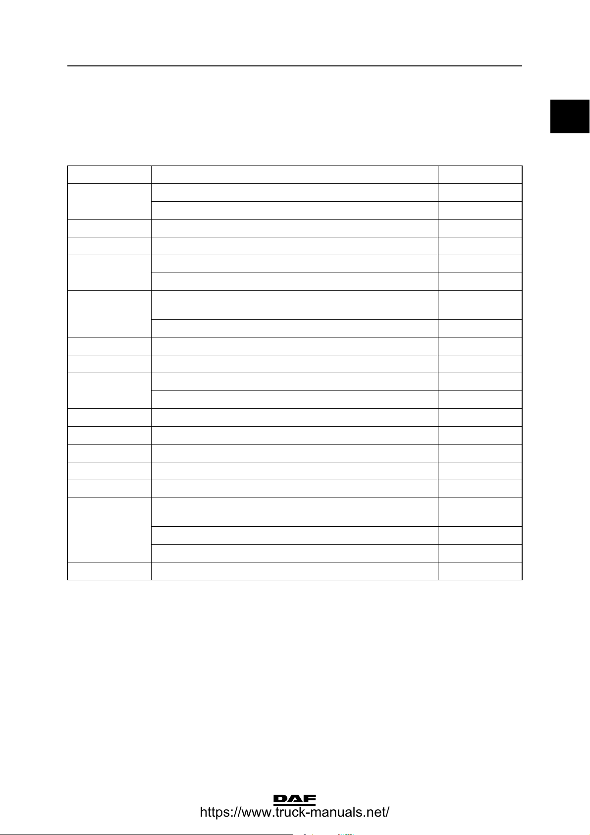
CONTENTS
Page Date
1. CHASSIS. . . . . . . . . . . . . . . . . . . . . . . . . . . . . . . . . . . . . . . . . . . . . . . . . . . . . . . 1-1 . . . . . 200448
1.1 General . . . . . . . . . . . . . . . . . . . . . . . . . . . . . . . . . . . . . . . . . . . . . . . . . . . 1-1 . . . . . 200448
2. STABILISERS, TORQUE RODS AND LEAF SUSPENSION. . . . . . . . . . . . . . . 2-1 . . . . . 200448
2.1 General . . . . . . . . . . . . . . . . . . . . . . . . . . . . . . . . . . . . . . . . . . . . . . . . . . . 2-1 . . . . . 200448
2.2 Tightening torques. . . . . . . . . . . . . . . . . . . . . . . . . . . . . . . . . . . . . . . . . . . 2-1 . . . . . 200448
3. REAR AXLE ALIGNMENT . . . . . . . . . . . . . . . . . . . . . . . . . . . . . . . . . . . . . . . . . 3-1 . . . . . 200448
3.1 General . . . . . . . . . . . . . . . . . . . . . . . . . . . . . . . . . . . . . . . . . . . . . . . . . . . 3-1 . . . . . 200448
4. FAG . . . . . . . . . . . . . . . . . . . . . . . . . . . . . . . . . . . . . . . . . . . . . . . . . . . . . . . . . . . 4-1 . . . . . 200448
4.1 General . . . . . . . . . . . . . . . . . . . . . . . . . . . . . . . . . . . . . . . . . . . . . . . . . . . 4-1 . . . . . 200448
https://www.truck-manuals.net/

TECHNICAL DATA
2
©
200448
Contents
0
ΧΦ65/75/85 series
9
https://www.truck-manuals.net/
©
200448 1-1
Chassis
TECHNICAL DATA
ΧΦ65/75/85 series
9
0
1. CHASSIS
1.1 GENERAL
Chassis materials
(1) KF 500 and KF 600 are "High Tensile Strength" types of steel.
Type Chassis type Material
FT Side member thickness 6 mm KF 600
(1)
Side member thickness 7 mm KF 500
(1)
FTG n/a KF 500
(1)
FTP n/a KF 600
(1)
FTS Side member height 260 mm KF 500
(1)
Side member height 310 mm KF 375
FTT RHD version: side member height 260 mm, side member
thickness 7 mm KF 500
(1)
Other versions KF 375
FA n/a KF 375
FAC n/a KF 375
FAD Side member height 310 mm, side member thickness 6 mm KF 600
(1)
Other versions KF 375
FAG n/a KF 375
FAL n/a KF 375
FAN n/a KF 375
FAR n/a KF 375
FAS n/a KF 375
FAT RHD version: side member height 260 mm, side member
thickness 7 mm KF 500
(1)
Side member height 310 mm, side member thickness 6 mm KF 600
(1)
Other versions KF 375
FAX n/a KF 375
https://www.truck-manuals.net/

TECHNICAL DATA
1-2
©
200448
Chassis
0
ΧΦ65/75/85 series
9
https://www.truck-manuals.net/
©
200448 2-1
Stabilisers, torque rods and leaf suspension
TECHNICAL DATA
ΧΦ65/75/85 series
9
0
2. STABILISERS, TORQUE RODS AND LEAF SUSPENSION
2.1 GENERAL
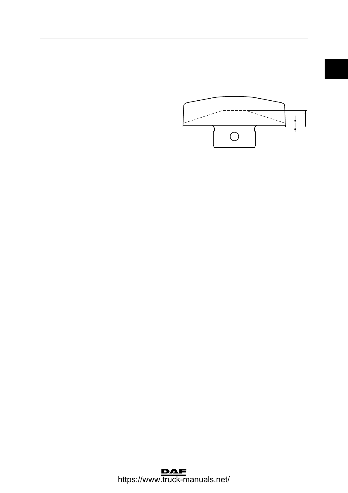
Minimum dimensions of wearing plates
If one of the dimensions of the wearing plates, on
which the spring assembly rests, is smaller than
indicated by the dotted line in the opposite
drawing, the wearing plates must be replaced.
Alignment plate/tandem axle spring clearance
If applicable, the clearance between the align-
ment plate and the tandem axle is: 1.5 - 2.5 mm.
2.2 TIGHTENING TORQUES
The tightening torques stated in this section are
different from the standard tightening torques
stated in the overview of the standard tightening
torques. The other threaded connections not
specified must therefore be tightened to the
torque stated in the overview of standard
tightening torques.
When attachment bolts and nuts are replaced, it
is important that - unless stated otherwise - these
bolts and nuts are of exactly the same length and
property class as those removed.
3
15
W9 00 013
https://www.truck-manuals.net/
TECHNICAL DATA
2-2
©
200448
Stabilisers, torque rods and leaf suspension
0
ΧΦ65/75/85 series
9
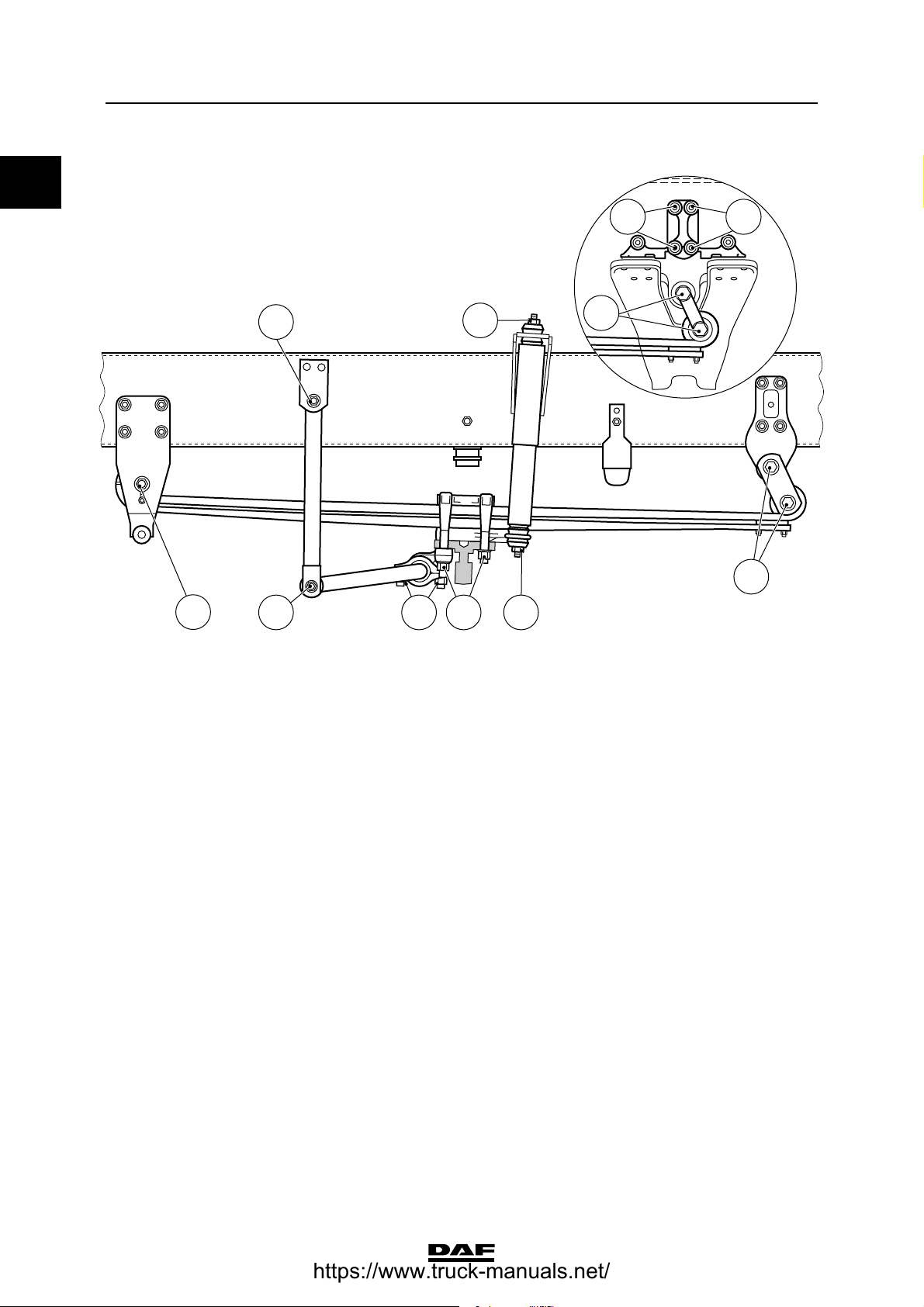
Front axle, leaf-sprung
(1) Evenly tighten the two U-bolt nuts alternately.
(2) Only applies in case of tandem axle/trailing axle
A Attachment bolt M24 for spring assembly,
property class 10.9 880 Nm
B U-bolt nut
- if flange nut M20, with yellow washer 450 ≥ 40 Nm
(1)
- if yellow zinc-plated hexagonal nut
M20, property class 10, with black
washer 400 ≥ 40 Nm
(1)
C Self-locking nut M16 for shock absorber 65 Nm
D Attachment bolt/nut M16 for stabiliser rod
shackle, property class 10.9/10 260 ≥ 20 Nm
E Attachment bolt/nut M12 for stabiliser rod
bearing bush cover, property class 10.9/10 110 ≥ 8 Nm
F Attachment bolt/nut M14 for spring
bracket, property class 10.9/10 170 ≥ 15 Nm
(2)
C9 00 477
A
B C
C
D
D
A
F F
A
E
https://www.truck-manuals.net/
©
200448 2-3
Stabilisers, torque rods and leaf suspension
TECHNICAL DATA
ΧΦ65/75/85 series
9
0
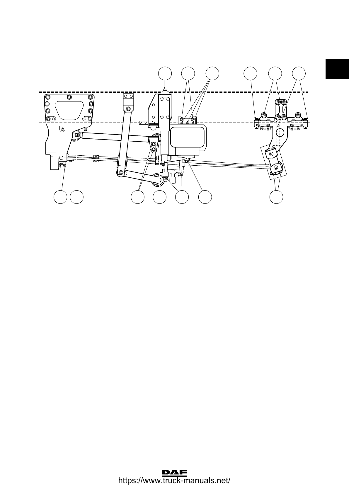
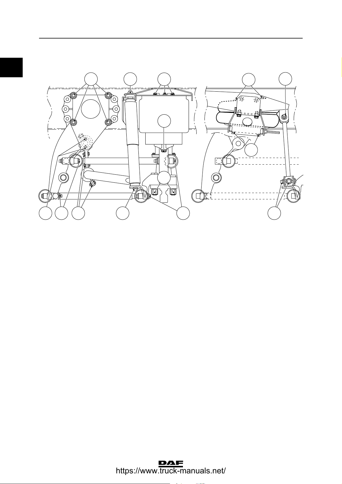
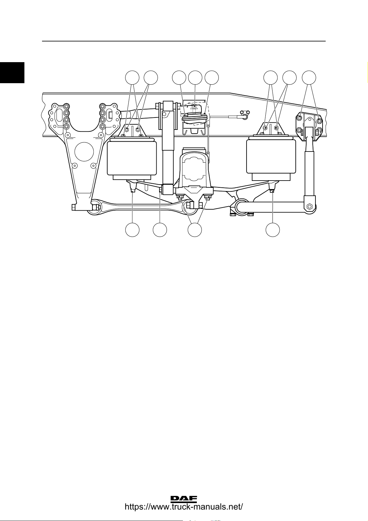
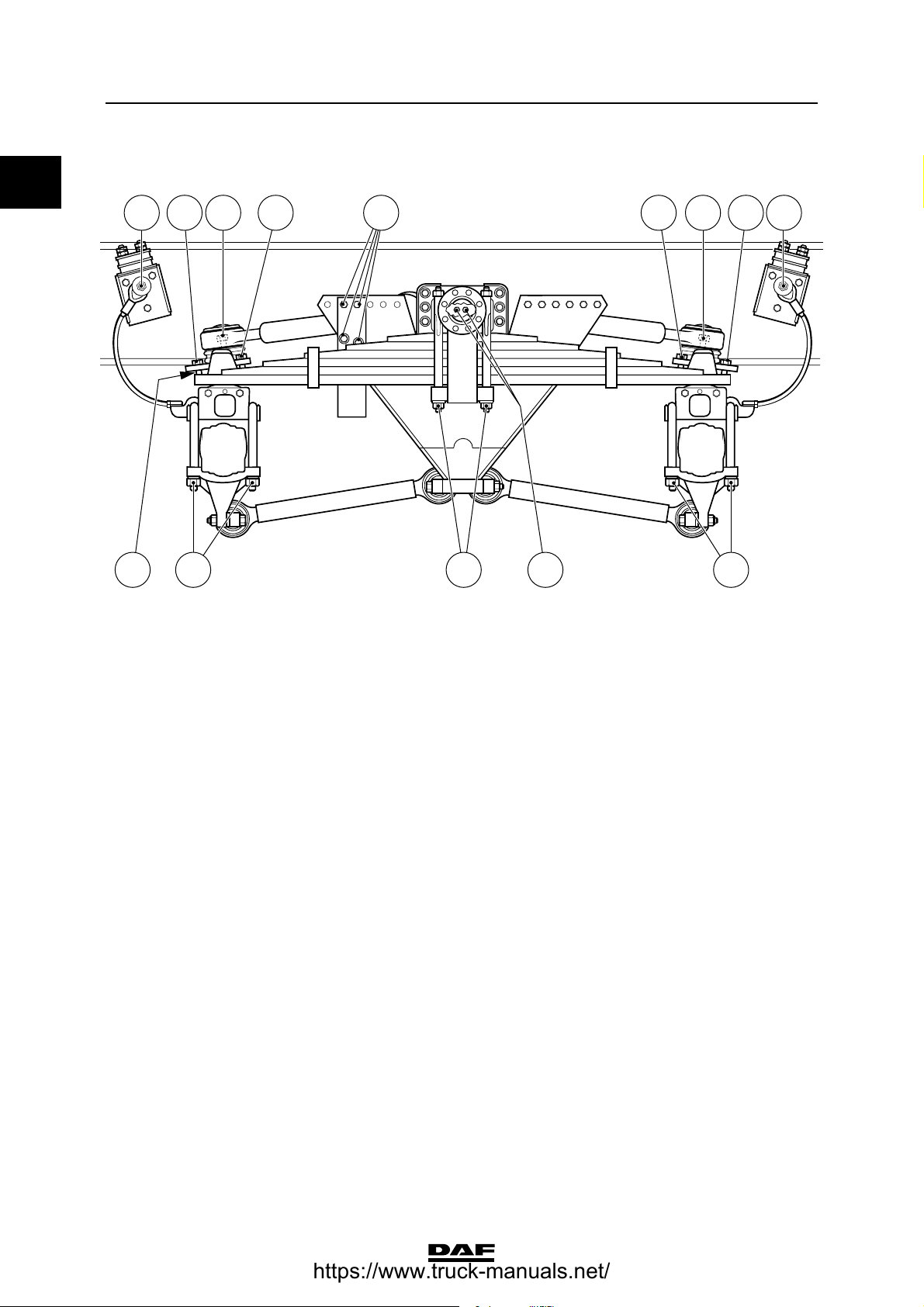
Front axle, air-sprung
(1) Evenly tighten the two U-bolt nuts alternately.
(2) Bellows must first be tightened on the chassis side.
A Attachment bolt M16 for torque rod,
property class 10.9 260 ≥ 20 Nm
B U-bolt nut
- if flange nut M22 700 ≥ 50 Nm
(1)
- if yellow zinc-plated hexagonal nut
M22, property class 10, with black
washer 530 ≥ 40 Nm
(1)
C Attachment bolt M16 for bellows, property
class 8.8 195 Nm
(2)
D Attachment nut M10 for bellows, property
class 10 46 Nm
(2)
E Attachment bolt/nut M16 for spring
bracket, property class 10.9/10 260 ≥ 20 Nm
F Attachment bolt/nut M14 for spring
bracket, property class 10.9/10 170 ≥ 15 Nm
G Self-locking nut M16 for shock absorber 65 Nm
H Attachment bolt/nut M12 for bellows
support, property class 10.9/10 110 ≥ 8 Nm
I Attachment bolt M10 for pin attachment of
spring assembly, property class 10.9 60 ≥ 4 Nm
J Attachment bolt M12 for torque rod
support, property class 10.9 110 ≥ 8 Nm
C9 00 479
A AJ B C I
FH DG E E
I
https://www.truck-manuals.net/
TECHNICAL DATA
2-4
©
200448
Stabilisers, torque rods and leaf suspension
0
ΧΦ65/75/85 series
9
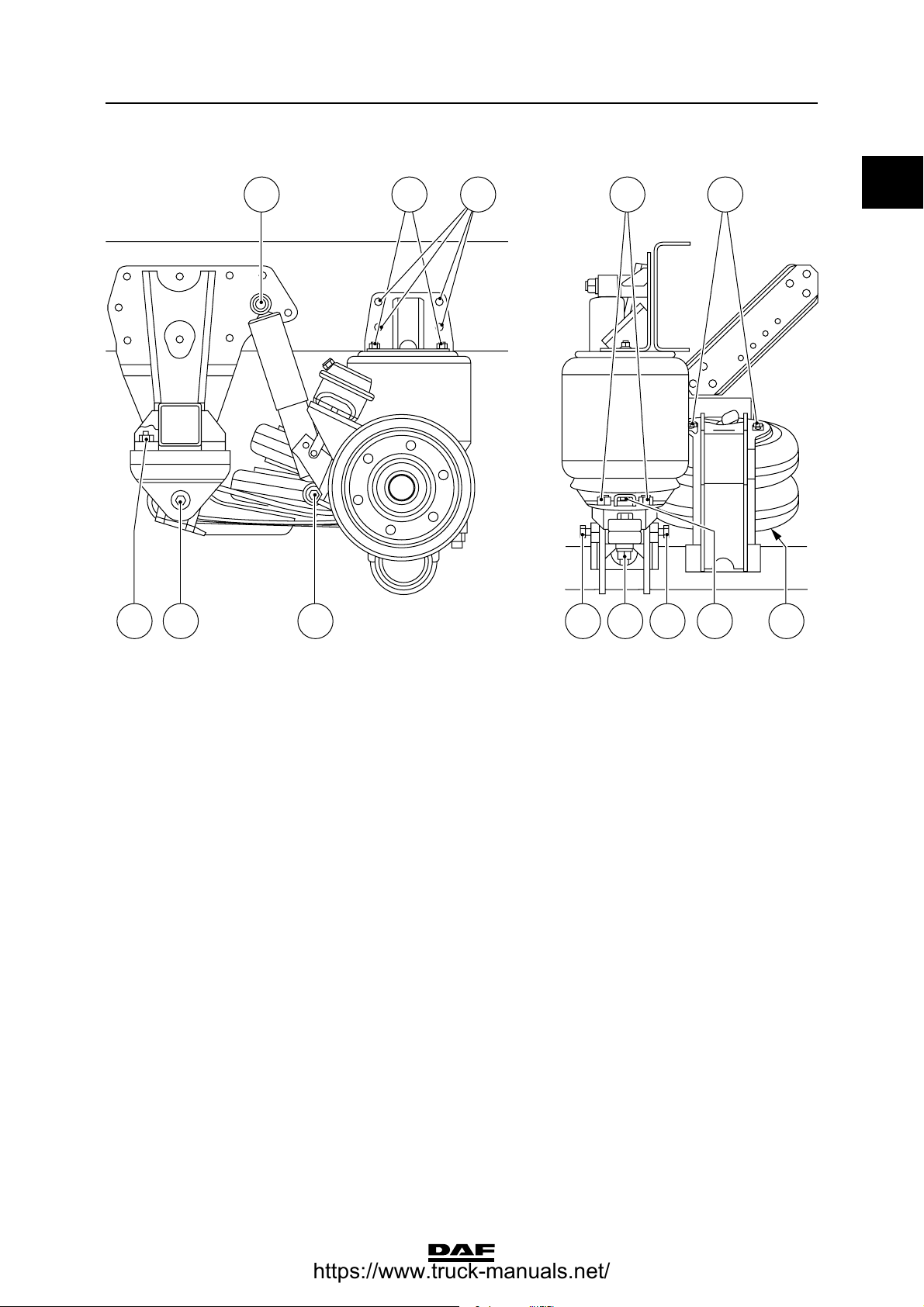
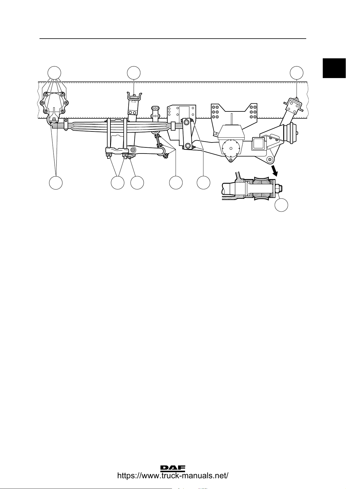
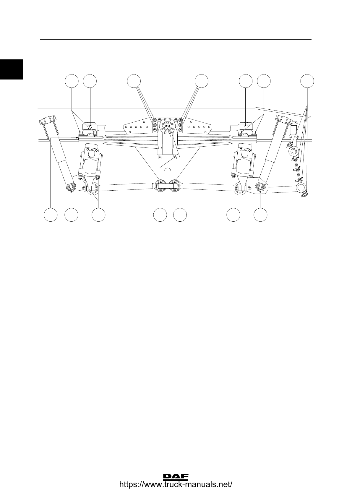
Leading rear axle, vehicle in FTG, FAG
version
(1) Bellows must first be tightened on the chassis side.
(2) Evenly tighten the two U-bolt nuts alternately.
A Attachment bolt/nut M16 for torque rod
(support), property class 10.9/10 260 ≥ 20 Nm
B Self-locking nut M16 for shock absorber 65 Nm
C Attachment nut M10 for bellows, property
class 10 46 Nm
(1)
D Attachment bolt M16 for bellows, property
class 10.9 195 Nm
(1)
E U-bolt nut
- if flange nut M22 700 ≥ 50 Nm
(2)
- if yellow zinc-plated hexagonal nut
M22, property class 10, with black
washer 530 ≥ 40 Nm
(2)
F Attachment bolt M8 for lifting bellows,
property class 10.9 20 Nm
G Attachment bolt/nut for stabiliser bar
bracket
- if M14, property class 10.9/10 170 ≥ 15 Nm
- if M16, property class 10.9/10 260 ≥ 20 Nm
H Attachment bolts M8 for locking plate,
property class 10.9 30 Nm
C9 00 486
F
A B
F
E
BA A
D
GH A
A
C
https://www.truck-manuals.net/
©
200448 2-5
Stabilisers, torque rods and leaf suspension
TECHNICAL DATA
ΧΦ65/75/85 series
9
0
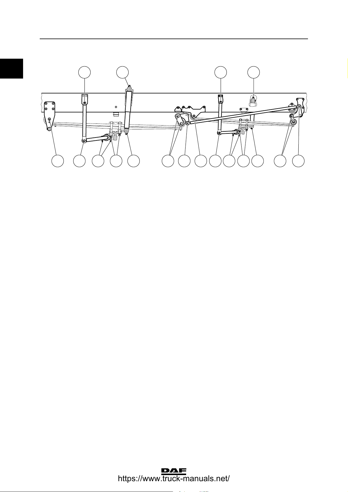
Leading rear axle, vehicle in FTP version
(1) Evenly tighten the two U-bolt nuts alternately.
A Attachment bolt M20 for shock absorber,
property class 8.8 250 ≥ 25 Nm
B Attachment nut M12 for bellows 30 Nm
C U-bolt nut M20, property class 10.9 553 Nm
(1)
D Attachment nut M10 for bellows 30 Nm
E Attachment bolt M16 for leaf spring,
property class 10.9 100 Nm
F Attachment bolt/nut M20 for leaf spring,
property class 10.9/10 553 Nm
G Attachment bolt/nut M24 for leaf spring 830 Nm
H Attachment bolt/nut M16 for spring
bracket, property class 10.9 310 Nm
I Attachment bolt/nut M10 for bellows
support, property class 10.9/10 60 ≥ 4 Nm
A
DEFEAG BH
B I DC
C9 00 481
https://www.truck-manuals.net/
TECHNICAL DATA
2-6
©
200448
Stabilisers, torque rods and leaf suspension
0
ΧΦ65/75/85 series
9
Double front axle
(1) Evenly tighten the two U-bolt nuts alternately.
(2) Fit new self-locking nut.
(3) Tighten until the split pin fits (max. 60).
It is not allowed to fit a self-locking nut to the ball
end with split pin hole.
A Attachment bolt M24 for spring assembly,
property class 10.9 880 Nm
B U-bolt nut
- if flange nut M20, with yellow washer 450 ≥ 40 Nm
(1)
- if yellow zinc-plated hexagonal nut
M20, property class 10, with black
washer 400 ≥ 40 Nm
(1)
C Self-locking nut M16 65 Nm
D Ball end nut
- if self-locking nut 285 Nm
(2)
- if castle nut 285 Nm
(3)
E Attachment bolt/nut M12 for stabiliser rod
bearing bush cover, property class 10.9/10 110 ≥ 8 Nm
F Attachment bolt/nut M16 for stabiliser rod
shackle, property class 10.9/10 260 ≥ 20 Nm
C900465
BEF EFA B C A DD AC
CF F C
A
https://www.truck-manuals.net/
©
200448 2-7
Stabilisers, torque rods and leaf suspension
TECHNICAL DATA
ΧΦ65/75/85 series
9
0
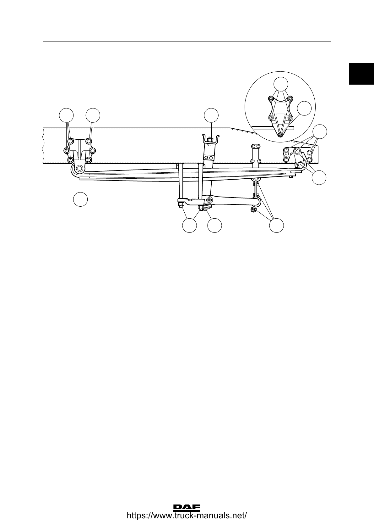
Rear axle, leaf suspension
(1) Evenly tighten the two U-bolt nuts alternately.
A Attachment bolt/nut M16 for spring
bracket, property class 10.9/10 260 ≥ 20 Nm
B Attachment bolt M24 for spring assembly,
property class 10.9 880 Nm
C U-bolt nut
- if flange nut M24, with black washer 750 ≥ 50 Nm
(1)
- if yellow zinc-plated hexagonal nut
M24, property class 10, with black
washer 615 ≥ 50 Nm
(1)
D Self-locking nut M16 for shock absorber 65 Nm
E Catch bolt M12, property class 10.9 68 ≥ 12 Nm
F Attachment bolt/nut M14 for stabiliser rod
bracket, property class 10.9/10 170 ≥ 15 Nm
DA A
B
C D F
C9 00 478
B
E
A
A
https://www.truck-manuals.net/
TECHNICAL DATA
2-8
©
200448
Stabilisers, torque rods and leaf suspension
0
ΧΦ65/75/85 series
9
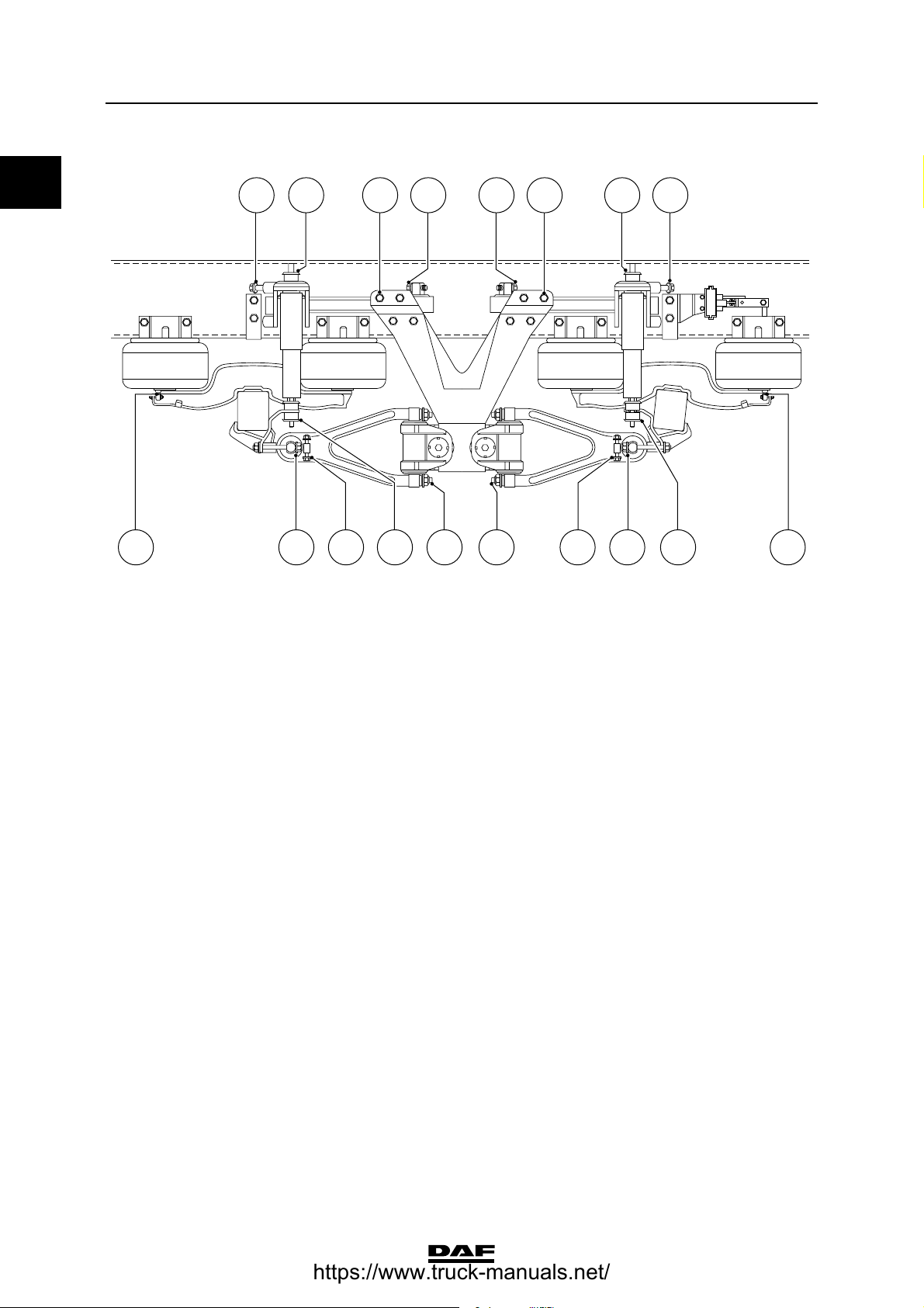
Rear axle, air-sprung
(1) Bellows must first be tightened on the chassis side.
(2) The high hexagonal nut can be recognised by the nut height, which is 1.5 x thread . Evenly tighten the two U-bolt nuts
alternately.
(3) The yellow zinc-plated hexagonal nut can be recognised by the nut height, which is 1 x thread . Evenly tighten the two U-bolt
nuts alternately.
A Attachment nut M10 for bellows, property
class 10 46 Nm
(1)
B Attachment bolt M16 for bellows, property
class 8.8 195 Nm
(1)
C Attachment bolt M20 for shock absorber,
property class 10.9 520 ≥ 40 Nm
D U-bolt nut
- if black high hexagonal nut M24 with
black washer 770 ≥ 60 Nm
(2)
- if yellow zinc-plated hexagonal nut
M24, property class 10, with black
washer 615 ≥ 50 Nm
(3)
E Clamping flange bolt M18 for triangular
link, property class 12.9 460 ≥ 40 Nm
F Attachment bolt M14, for triangular link
ball, property class 10.9 135 Nm
G Attachment bolt/nut M16 for stabiliser
shackle support, property class 10.9/10 260 ≥ 20 Nm
H Attachment bolt/nut M10 for bellows
support, property class 10.9/10 60 ≥ 4 Nm
C9 00 480
A H H
DCB B
AEE F G
https://www.truck-manuals.net/
©
200448 2-9
Stabilisers, torque rods and leaf suspension
TECHNICAL DATA
ΧΦ65/75/85 series
9
0
Trailing axle, leaf suspension
(1) Evenly tighten the two U-bolt nuts alternately.
A U-bolt nut
- if flange nut M24 750 ≥ 50 Nm
(1)
- if yellow zinc-plated hexagonal nut
M24, property class 10, with black
washer 615 ≥ 50 Nm
(1)
B Self-locking nut M16 65 Nm
C Shock absorber attachment nut 260 ≥ 20 Nm
D Attachment bolt/nut M16 for spring
bracket, property class 10.9/10 260 ≥ 20 Nm
E Attachment bolt/nut M14 for stabiliser rod
bracket, property class 10.9/10 170 ≥ 15 Nm
F Attachment bolt M10 for pin attachment of
spring assembly, property class 10.9 60 ≥ 4 Nm
G Attachment bolt/nut M12 for spring
shackle, property class 10.9/10 110 ≥ 8 Nm
A B
C9 00 483
B
F
B
C
E G
D
https://www.truck-manuals.net/
TECHNICAL DATA
2-10
©
200448
Stabilisers, torque rods and leaf suspension
0
ΧΦ65/75/85 series
9
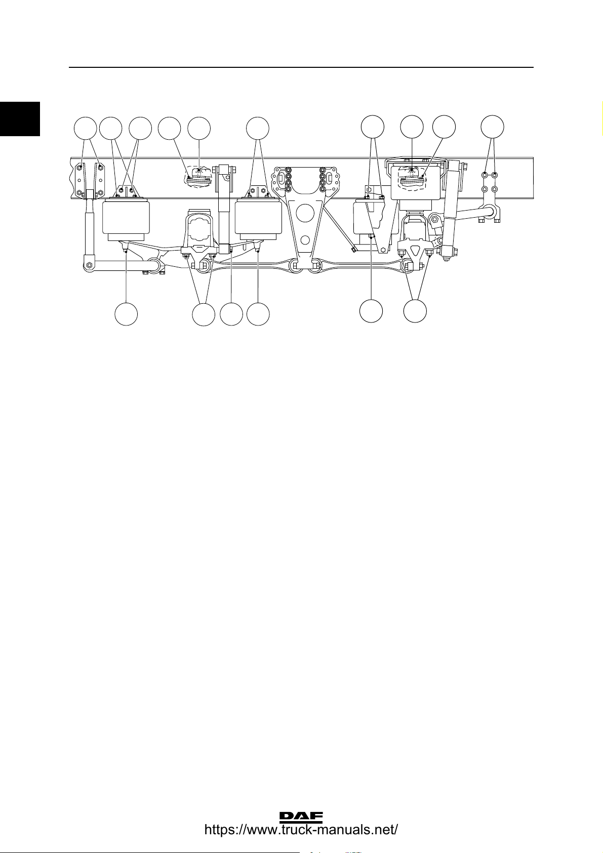
Trailing axle, air-sprung, 6 bellows version
(1) Bellows must first be tightened on the chassis side.
(2) The high hexagonal nut can be recognised by the nut height, which is 1.5 x thread . Evenly tighten the two U-bolt nuts
alternately.
(3) The yellow zinc-plated hexagonal nut can be recognised by the nut height, which is 1 x thread . Evenly tighten the two U-bolt
nuts alternately.
A Attachment nut M10 for bellows, property
class 10 46 Nm
(1)
B Clamping flange bolt M18 for triangular
link, property class 12.9 460 ≥ 40 Nm
C Attachment bolt M14, for triangular link
ball, property class 10.9 135 Nm
D U-bolt nut
- if black high hexagonal nut M24 with
black washer 770 ≥ 60 Nm
(2)
- if yellow zinc-plated hexagonal nut
M24, property class 10, with black
washer 615 ≥ 50 Nm
(3)
E Attachment bolt M16 for bellows, property
class 8.8 195 Nm
(1)
F Attachment bolt M20 for shock absorber,
property class 10.9 520 ≥ 40 Nm
G Attachment bolt/nut M16 for stabiliser
shackle support, property class 10.9/10 260 ≥ 20 Nm
H Attachment bolt/nut M10 for bellows
support, property class 10.9/10 60 ≥ 4 Nm
I Attachment bolt/nut M16 for stabiliser
shackle support, property class 10.9/10 260 ≥ 20 Nm
C900463
D
B G
E
A
A BI H A
D
E F E
C
C
https://www.truck-manuals.net/
©
200448 2-11
Stabilisers, torque rods and leaf suspension
TECHNICAL DATA
ΧΦ65/75/85 series
9
0
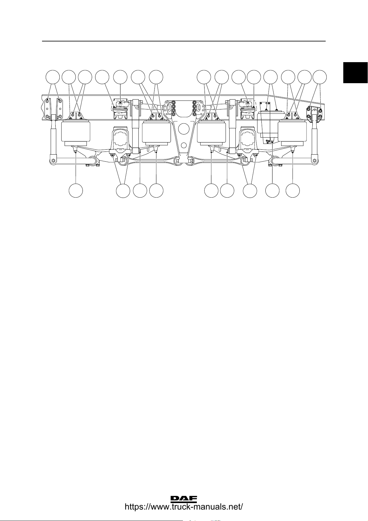
Trailing axle, air-sprung, 8 bellows version
(1) Bellows must first be tightened on the chassis side.
(2) The high hexagonal nut can be recognised by the nut height, which is 1.5 x thread . Evenly tighten the two U-bolt nuts
alternately.
(3) The yellow zinc-plated hexagonal nut can be recognised by the nut height, which is 1 x thread . Evenly tighten the two U-bolt
nuts alternately.
A Attachment nut M10 for bellows, property
class 10 46 Nm
(1)
B Clamping flange bolt M18 for triangular
link, property class 12.9 460 ≥ 40 Nm
C Attachment bolt M14, for triangular link
ball, property class 10.9 135 Nm
D Attachment bolt M16 for bellows, property
class 8.8 195 Nm
(1)
E U-bolt nut
- if black high hexagonal nut M24 with
black washer 770 ≥ 60 Nm
(2)
- if yellow zinc-plated hexagonal nut
M24, property class 10, with black
washer 615 ≥ 50 Nm
(3)
F Attachment bolt M20 for shock absorber,
property class 10.9 520 ≥ 40 Nm
G Attachment bolt/nut M16 for stabiliser
shackle support, property class 10.9/10 260 ≥ 20 Nm
H Attachment bolt/nut M10 for bellows
support, property class 10.9/10 60 ≥ 4 Nm
C9 00 482
A B C BCG H GA
E E
A AA
D DDF FD D
HHH
https://www.truck-manuals.net/
TECHNICAL DATA
2-12
©
200448
Stabilisers, torque rods and leaf suspension
0
ΧΦ65/75/85 series
9
Tandem axle, leaf-sprung, trapezoidal leaf
spring version
A Attachment bolt/nut M16 for arresting
cable 150 ≥ 20 Nm
B Attachment bolt M14, for triangular link
ball, property class 10.9 135 Nm
C Clamping flange bolt M18 for triangular
link, property class 12.9 460 ≥ 40 Nm
D U-bolt nut
- if flange nut M20 450 ≥ 40 Nm
(1)
- if yellow zinc-plated hexagonal nut
M20, property class 10, with black
washer 400 ≥ 40 Nm
(1)
E Attachment bolt M14, for bearing bush
plate, property class 10.9 170 ≥ 15 Nm
(2)
F Tie rod nut
if flange nut M22 650 ≥ 50 Nm
(1)
if yellow zinc-plated hexagonal nut M22,
property class 10, with black washer 480 ≥ 40 Nm
(1)
G Attachment bolt/nut M12 for alignment
plate, property class 10.9/10 110 ≥ 8 Nm
A C
FH
C9 00 485
C B
E
ABC CG
DD
https://www.truck-manuals.net/

©
200448 2-13
Stabilisers, torque rods and leaf suspension
TECHNICAL DATA
ΧΦ65/75/85 series
9
0
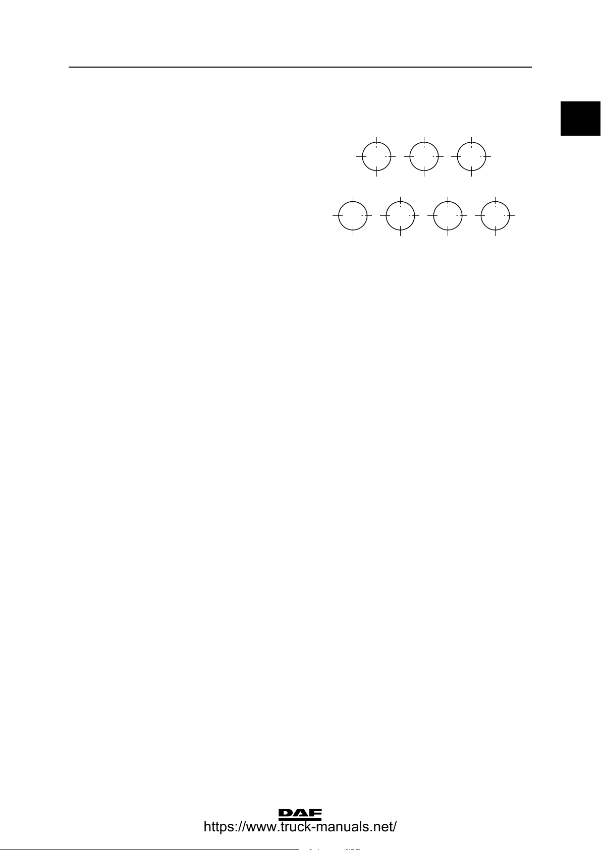
(1) Evenly tighten the two U-bolt/tie rod nuts alternately.
(2) Fasten with Loctite 243.
H Tighten the bolts according to the standard
tightening torque, in the order shown.
4 1 5
7 2 3 6
C9 00 144
https://www.truck-manuals.net/
TECHNICAL DATA
2-14
©
200448
Stabilisers, torque rods and leaf suspension
0
ΧΦ65/75/85 series
9
Tandem axle, leaf-sprung, parabolic leaf
spring version
A Clamping flange bolt M18 for triangular
link, property class 12.9 460 ≥ 40 Nm
B Attachment bolt M14, for triangular link
ball, property class 10.9 135 Nm
C Self-locking nut M16 for shock absorber 65 Nm
D U-bolt nut
- if flanged nut 450 ≥ 40 Nm
(1)
- if yellow zinc-plated hexagonal nut
M20, property class 10, with black
washer 400 ≥ 40 Nm
(1)
E Attachment bolt M14, for bearing bush
plate, property class 10.9 170 ≥ 15 Nm
(2)
F Tie rod nut
- if flanged nut 650 ≥ 50 Nm
(1)
- if yellow zinc-plated hexagonal nut
M22, property class 10, with black
washer 480 ≥ 40 Nm
(1)
G Attachment bolt M16 for pivot pin flange,
property class 10.9 260 ≥ 20 Nm
H Attachment bolt/nut M14 for stabiliser rod
bracket, property class 10.9/10 170 ≥ 15 Nm
C9 00 484
A B AB
C CDFI E
HG
G
D
https://www.truck-manuals.net/
©
200448 2-15
Stabilisers, torque rods and leaf suspension
TECHNICAL DATA
ΧΦ65/75/85 series
9
0
(1) Evenly tighten the two U-bolt/tie rod nuts alternately.
(2) Fasten with Loctite 243.
I Tighten the bolts according to the standard
tightening torque, in the order shown.
4 1 5
7 2 3 6
C9 00 144
https://www.truck-manuals.net/
TECHNICAL DATA
2-16
©
200448
Stabilisers, torque rods and leaf suspension
0
ΧΦ65/75/85 series
9
Tandem axle, air-sprung, Meritor version
A Attachment bolt/nut M16 for torque rod,
property class 10.9/10 260 ≥ 60 Nm
B Tighten shock absorber attachment nut
until the rubber sleeve and the steel ring
have the same diameter.
C Attachment bolt/nut M22 for yoke, property
class 10.9/10 750 Nm
D Attachment bolt for bellows 1/2" UNC 34 ≥ 7 Nm
E Attachment bolt/nut M16 for torque rod,
property class 10.9/10 260 ≥ 60 Nm
F Attachment bolt/nut M10 for torque rod,
property class 10.9/10 60 ≥ 4 Nm
G Attachment nut M20 for torque rod,
property class 10.9 520 ≥ 40 Nm
C9 00 404
A B
D E F B BG
C A A C B A
FE DG
https://www.truck-manuals.net/
©
200448 3-1
Rear axle alignment
TECHNICAL DATA
ΧΦ65/75/85 series
9
0
3. REAR AXLE ALIGNMENT
3.1 GENERAL
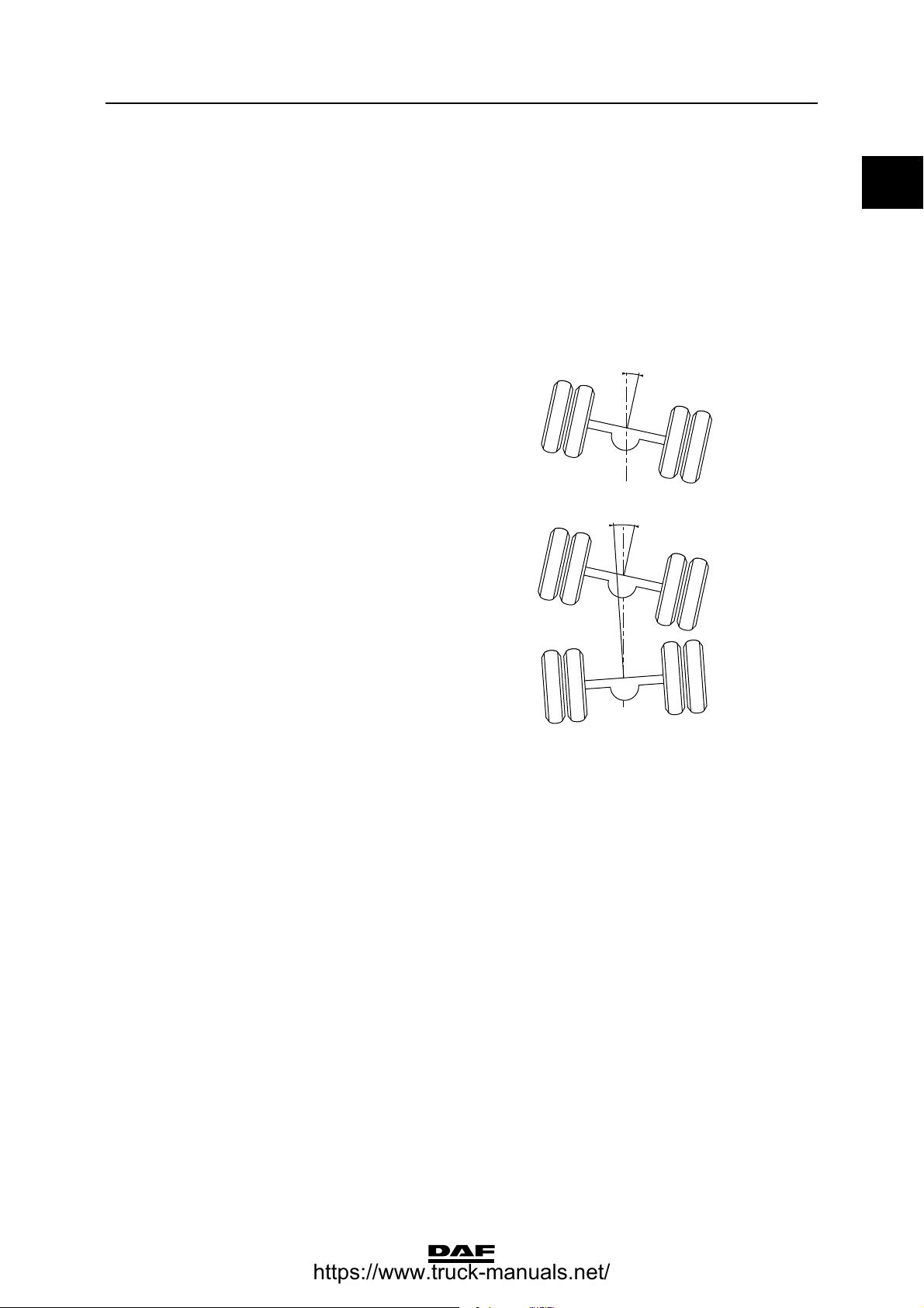
Rear axle misalignment standard
The angle achieved by the driven rear axle
relative to the vehicle centreline is calculated
from the angle achieved by both wheels of this
axle relative to the vehicle centreline. See "Rear
axle alignment".
Driven axle relative to the vehicle centreline:
- max. 4 mm/m (angle A in drawing).
This value also applies to the individual
tandem axles and the driven axle of the
trailing axle suspension.
Non-parallelism of the rear tandem axle relative
to the front tandem axle:
- max. 2 mm/m (angle B in drawing).
C9 00 123
A
C9 00 124
B
https://www.truck-manuals.net/
TECHNICAL DATA
3-2
©
200448
Rear axle alignment
0
ΧΦ65/75/85 series
9
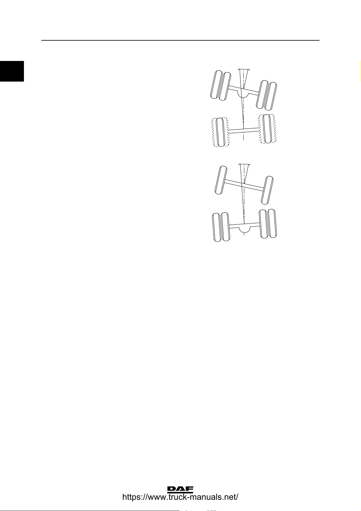
Non-parallelism of the trailing axle relative to the
driven axle:
- max. 2 mm/m (angle C in drawing).
Non-parallelism of the unsteered leading rear
axle (FTP) relative to the driven axle:
- max. 2 mm/m (angle D in drawing).
C9 00 235
C
C9 00 519
D
https://www.truck-manuals.net/
©
200448 4-1
FAG
TECHNICAL DATA
ΧΦ65/75/85 series
9
0
4. FAG
4.1 GENERAL
Valve adjustment
Control values/adjustment of height-control
valve, axle load ratio 6.0/10.0 and fitted with
leaf spring suspension (DAF no. 1368293)
Pressure-limiting valve 7.0 bar
Pressure-relief valve 0.5 bar
Lever length 60 mm
Joint axle load of leading rear axle/
drive shaft (N)
Bellows pressure (bar)
30,000 0.4
40,000 0.7
50,000 1.1
60,000 1.5
70,000 1.9
80,000 2.2
90,000 2.6
100,000 3.0
110,000 3.4
120,000 3.7
130,000 4.1
140,000 4.5
150,000 4.9
160,000 5.2
170,000 5.6
180,000 6.0
190,000 6.4
200,000 6.7
https://www.truck-manuals.net/

TECHNICAL DATA
4-2
©
200448
FAG
0
ΧΦ65/75/85 series
9
Control values/adjustment of height-control
valve, axle load ratio 6.0/10.0 and fitted with
leaf spring suspension (DAF no. 1386990)
Lever length 70 mm
Joint axle load of leading rear axle/
drive shaft (N)
Bellows pressure (bar)
30,000 0.4
40,000 0.7
50,000 1.1
60,000 1.5
70,000 1.9
80,000 2.2
90,000 2.6
100,000 3.0
110,000 3.4
120,000 3.7
130,000 4.1
140,000 4.5
150,000 4.9
160,000 5.2
170,000 5.6
180,000 6.0
190,000 6.4
200,000 6.7
https://www.truck-manuals.net/

©
200448 4-3
FAG
TECHNICAL DATA
ΧΦ65/75/85 series
9
0
Control values/adjustment of height-control
valve, axle load ratio 7.1/11.5 and fitted with
leaf spring suspension (DAF no. 1368293)
Lever length 60 mm
Joint axle load of leading rear axle/
drive shaft (N)
Bellows pressure (bar)
30,000 0.4
40,000 0.8
50,000 1.1
60,000 1.5
70,000 1.9
80,000 2.3
90,000 2.7
100,000 3.1
110,000 3.4
120,000 3.8
130,000 4.2
140,000 4.6
150,000 5.0
160,000 5.3
170,000 5.7
180,000 6.1
190,000 6.5
200,000 6.9
https://www.truck-manuals.net/
TECHNICAL DATA
4-4
©
200448
FAG
0
ΧΦ65/75/85 series
9
Control values/adjustment of height-control
valve, axle load ratio 7.1/11.5 and fitted with
leaf spring suspension (DAF no. 1386990)
Lever length 70 mm
Joint axle load of leading rear axle/
drive shaft (N)
Bellows pressure (bar)
30,000 0.4
40,000 0.8
50,000 1.1
60,000 1.5
70,000 1.9
80,000 2.3
90,000 2.7
100,000 3.1
110,000 3.4
120,000 3.8
130,000 4.2
140,000 4.6
150,000 5.0
160,000 5.3
170,000 5.7
180,000 6.1
190,000 6.5
200,000 6.9
https://www.truck-manuals.net/
©
200448 4-5
FAG
TECHNICAL DATA
ΧΦ65/75/85 series
9
0
Control values/adjustment of height-control
valve, axle load ratio 7.5/11.5 and fitted with
leaf spring suspension (DAF no. 1368293)
Lever length 60 mm
Joint axle load of leading rear axle/
drive shaft (N)
Bellows pressure (bar)
30,000 0.4
40,000 0.8
50,000 1.2
60,000 1.6
70,000 2.0
80,000 2.4
90,000 2.8
100,000 3.2
110,000 3.6
120,000 4.0
130,000 4.4
140,000 4.8
150,000 5.2
160,000 5.5
170,000 5.9
180,000 6.3
190,000 6.7
200,000 7.0
https://www.truck-manuals.net/

TECHNICAL DATA
4-6
©
200448
FAG
0
ΧΦ65/75/85 series
9
Control values/adjustment of height-control
valve, axle load ratio 7.5/11.5 and fitted with
leaf spring suspension (DAF no. 1368293)
Lever length 70 mm
Joint axle load of leading rear axle/
drive shaft (N)
Bellows pressure (bar)
30,000 0.3
40,000 0.7
50,000 1.1
60,000 1.4
70,000 1.8
80,000 2.4
90,000 2.5
100,000 2.9
110,000 3.3
120,000 3.6
130,000 4.0
140,000 4.4
150,000 4.7
160,000 5.1
170,000 5.5
180,000 5.8
190,000 6.2
200,000 6.6
https://www.truck-manuals.net/
Loading...