


3 |
STRUCTURE |
CF65/75/85 series
TECHNICAL DATA
DIAGNOSTICS
MECHANICAL GEARBOX CONTROL
PNEUMATICALLY ASSISTED GEARBOX CONTROL (SERVOSHIFT)
GEARBOX - PNEUMATIC SECTION
ZF 6S-850 GEARBOX
ZF 8/9/16S-109 GEARBOX
ZF 8/16S-151/181 AND 16S-221 GEARBOXES
EATON FS/6309A GEARBOX
AUTOMATIC GEARBOXES
CLUTCH
PROP SHAFTS
ZF INTARDER
PTO
AS TRONIC GEARBOX
0
1
2
3
4
5
6
7
8
9
10
11
12
13
14
200337 
 https://www.truck-manuals.net/
https://www.truck-manuals.net/

3 |
TECHNICAL DATA |
|
|
|
|
CF65/75/85 Serie |
Contents |
|
CONTENTS
Page Date |
0 |
|
1. MECHANICAL GEARBOX CONTROL . . . . . . . . . . . . . . . . . . . . . . . . . . . . . . . . . . . . 1-1 . . . . 200337 1.1 General . . . . . . . . . . . . . . . . . . . . . . . . . . . . . . . . . . . . . . . . . . . . . . . . . . . . . . . . . 1-1 . . . . 200337 1.2 Tightening torques . . . . . . . . . . . . . . . . . . . . . . . . . . . . . . . . . . . . . . . . . . . . . . . . 1-3 . . . . 200337
2. PNEUMATICALLY ASSISTED GEARBOX CONTROL (SERVOSHIFT) . . . . . . . 2-1 . . . . 200337 2.1 General . . . . . . . . . . . . . . . . . . . . . . . . . . . . . . . . . . . . . . . . . . . . . . . . . . . . . . . . . 2-1 . . . . 200337 2.2 Tightening torques . . . . . . . . . . . . . . . . . . . . . . . . . . . . . . . . . . . . . . . . . . . . . . . . 2-1 . . . . 200337
3. PNEUMATIC SECTION OF GEARBOX . . . . . . . . . . . . . . . . . . . . . . . . . . . . . . . . . . . 3-1 . . . . 200337 3.1 General . . . . . . . . . . . . . . . . . . . . . . . . . . . . . . . . . . . . . . . . . . . . . . . . . . . . . . . . . 3-1 . . . . 200337 3.2 Tightening torques . . . . . . . . . . . . . . . . . . . . . . . . . . . . . . . . . . . . . . . . . . . . . . . . 3-4 . . . . 200337
4. ZF 6S-850 GEARBOX . . . . . . . . . . . . . . . . . . . . . . . . . . . . . . . . . . . . . . . . . . . . . . . . . . 4-1 . . . . 200337 4.1 General . . . . . . . . . . . . . . . . . . . . . . . . . . . . . . . . . . . . . . . . . . . . . . . . . . . . . . . . . 4-1 . . . . 200337 4.2 Tightening torques . . . . . . . . . . . . . . . . . . . . . . . . . . . . . . . . . . . . . . . . . . . . . . . . 4-2 . . . . 200337 4.3 Filling capacities . . . . . . . . . . . . . . . . . . . . . . . . . . . . . . . . . . . . . . . . . . . . . . . . . . 4-2 . . . . 200337
5. ZF 8/9/16S-109 GEARBOX . . . . . . . . . . . . . . . . . . . . . . . . . . . . . . . . . . . . . . . . . . . . . . 5-1 . . . . 200337 5.1 General . . . . . . . . . . . . . . . . . . . . . . . . . . . . . . . . . . . . . . . . . . . . . . . . . . . . . . . . . 5-1 . . . . 200337 5.2 Tightening torques . . . . . . . . . . . . . . . . . . . . . . . . . . . . . . . . . . . . . . . . . . . . . . . . 5-2 . . . . 200337 5.3 Filling capacities . . . . . . . . . . . . . . . . . . . . . . . . . . . . . . . . . . . . . . . . . . . . . . . . . . 5-4 . . . . 200337
6. ZF 8/16S-151/181 AND 16S-221 GEARBOXES . . . . . . . . . . . . . . . . . . . . . . . . . . . . 6-1 . . . . 200337 6.1 General . . . . . . . . . . . . . . . . . . . . . . . . . . . . . . . . . . . . . . . . . . . . . . . . . . . . . . . . . 6-1 . . . . 200337 6.2 Tightening torques . . . . . . . . . . . . . . . . . . . . . . . . . . . . . . . . . . . . . . . . . . . . . . . . 6-2 . . . . 200337 6.3 Filling capacities . . . . . . . . . . . . . . . . . . . . . . . . . . . . . . . . . . . . . . . . . . . . . . . . . . 6-4 . . . . 200337
7. EATON FS/6309A GEARBOX . . . . . . . . . . . . . . . . . . . . . . . . . . . . . . . . . . . . . . . . . . . 7-1 . . . . 200337 7.1 General . . . . . . . . . . . . . . . . . . . . . . . . . . . . . . . . . . . . . . . . . . . . . . . . . . . . . . . . . 7-1 . . . . 200337 7.2 Tightening torques . . . . . . . . . . . . . . . . . . . . . . . . . . . . . . . . . . . . . . . . . . . . . . . . 7-2 . . . . 200337 7.3 Filling capacities . . . . . . . . . . . . . . . . . . . . . . . . . . . . . . . . . . . . . . . . . . . . . . . . . . 7-3 . . . . 200337
8. ALLISON AUTOMATIC GEARBOX . . . . . . . . . . . . . . . . . . . . . . . . . . . . . . . . . . . . . . 8-1 . . . . 200337 8.1 General . . . . . . . . . . . . . . . . . . . . . . . . . . . . . . . . . . . . . . . . . . . . . . . . . . . . . . . . . 8-1 . . . . 200337 8.2 Tightening torques . . . . . . . . . . . . . . . . . . . . . . . . . . . . . . . . . . . . . . . . . . . . . . . . 8-2 . . . . 200337 8.3 Filling capacities . . . . . . . . . . . . . . . . . . . . . . . . . . . . . . . . . . . . . . . . . . . . . . . . . . 8-3 . . . . 200337
9. CLUTCH . . . . . . . . . . . . . . . . . . . . . . . . . . . . . . . . . . . . . . . . . . . . . . . . . . . . . . . . . . . . . . 9-1 . . . . 200337 9.1 General . . . . . . . . . . . . . . . . . . . . . . . . . . . . . . . . . . . . . . . . . . . . . . . . . . . . . . . . . 9-1 . . . . 200337 9.2 Tightening torques . . . . . . . . . . . . . . . . . . . . . . . . . . . . . . . . . . . . . . . . . . . . . . . . 9-5 . . . . 200337 9.3 Filling capacities . . . . . . . . . . . . . . . . . . . . . . . . . . . . . . . . . . . . . . . . . . . . . . . . . . 9-6 . . . . 200337
10. PROP SHAFTS . . . . . . . . . . . . . . . . . . . . . . . . . . . . . . . . . . . . . . . . . . . . . . . . . . . . . . . . 10-1 . . . 200337 10.1 General . . . . . . . . . . . . . . . . . . . . . . . . . . . . . . . . . . . . . . . . . . . . . . . . . . . . . . . . . 10-1 . . . 200337 10.2 Tightening torques . . . . . . . . . . . . . . . . . . . . . . . . . . . . . . . . . . . . . . . . . . . . . . . . 10-2 . . . 200337 10.3 Filling capacities . . . . . . . . . . . . . . . . . . . . . . . . . . . . . . . . . . . . . . . . . . . . . . . . . . 10-3 . . . 200337
11. ZF INTARDER . . . . . . . . . . . . . . . . . . . . . . . . . . . . . . . . . . . . . . . . . . . . . . . . . . . . . . . . . 11-1 . . . 200337 11.1 General . . . . . . . . . . . . . . . . . . . . . . . . . . . . . . . . . . . . . . . . . . . . . . . . . . . . . . . . . 11-1 . . . 200337 11.2 Tightening torques . . . . . . . . . . . . . . . . . . . . . . . . . . . . . . . . . . . . . . . . . . . . . . . . 11-1 . . . 200337
200337 |
|
|
|
6-1 |
|
https://www.truck-manuals.net/ |
|||||
|
|
||||

TECHNICAL DATA |
|
3 |
|
|
|
|
|
Contents |
CF65/75/85 Serie |
||
|
Page |
Date |
|
12. PTO . . . . . . . . . . . . . . . . . . . . . . . . . . . . . . . . . . . . . . . . . . . . . . . . . . . . . . . . . . . . . . . . . . 12-1 . . . 200337 0 12.1 General . . . . . . . . . . . . . . . . . . . . . . . . . . . . . . . . . . . . . . . . . . . . . . . . . . . . . . . . . 12-1 . . . 200337 12.2 Tightening torques . . . . . . . . . . . . . . . . . . . . . . . . . . . . . . . . . . . . . . . . . . . . . . . . 12-2 . . . 200337 12.3 Filling capacities . . . . . . . . . . . . . . . . . . . . . . . . . . . . . . . . . . . . . . . . . . . . . . . . . . 12-4 . . . 200337
13. AS TRONIC GEARBOX . . . . . . . . . . . . . . . . . . . . . . . . . . . . . . . . . . . . . . . . . . . . . . . . 13-1 . . . 200337 13.1 General . . . . . . . . . . . . . . . . . . . . . . . . . . . . . . . . . . . . . . . . . . . . . . . . . . . . . . . . . 13-1 . . . 200337 13.2 Tightening torques . . . . . . . . . . . . . . . . . . . . . . . . . . . . . . . . . . . . . . . . . . . . . . . . 13-2 . . . 200337 13.3 Filling capacities . . . . . . . . . . . . . . . . . . . . . . . . . . . . . . . . . . . . . . . . . . . . . . . . . . 13-4 . . . 200337
6-2 |
|
|
|
200337 |
|
https://www.truck-manuals.net/ |
|||||
|
|
||||

3 |
|
TECHNICAL DATA |
||
|
|
|
||
CF65/75/85 series |
Mechanical gearbox control |
|||
1. |
MECHANICAL GEARBOX CONTROL |
|
|
|
1.1 |
GENERAL |
|
|
0 |
|
|
|
|
|
|
|
|
|
|
V300382
-Within the entire CF65/75/85 vehicle series many gearbox variations as well as the accompanying controls are possible, both mechanical and pneumatic.
-A gearbox with a splitter and range-change switch will be equipped with several pneumatic valves.
200337 |
|
|
|
1-1 |
|
https://www.truck-manuals.net/ |
|||||
|
|
||||
|
TECHNICAL DATA |
3 |
|
Mechanical gearbox control |
CF65/75/85 series |
|
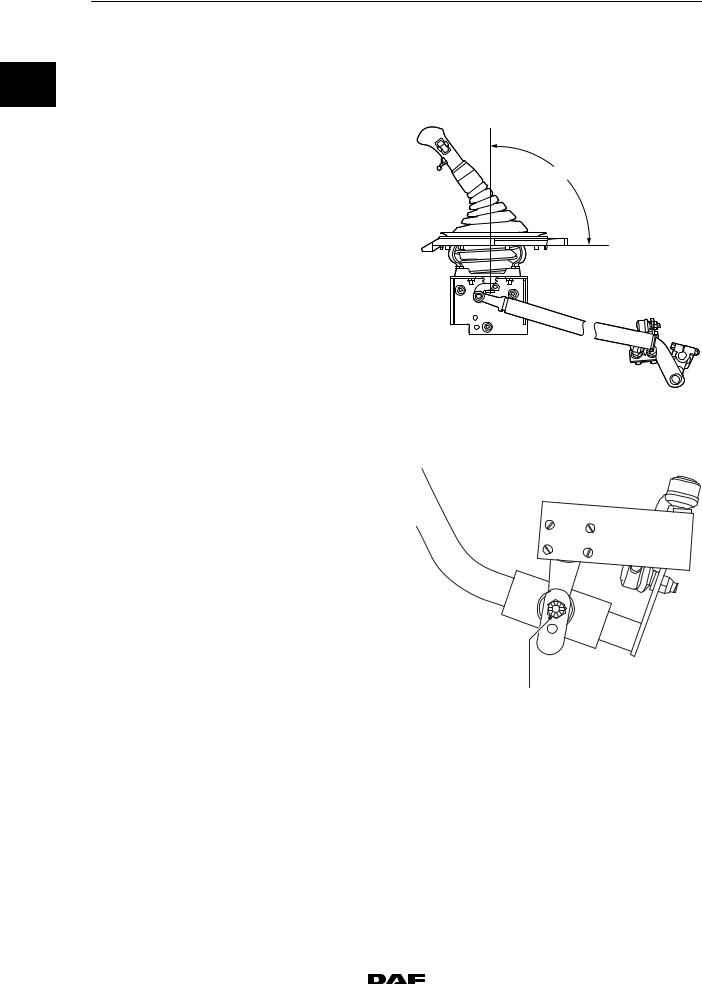
ADJUSTING THE LINKAGE MECHANISM |
|
0 |
Vehicle series CF65/75/85 LHD/RHD with |
|
ZF 6S-850, 8/9/16S-109, 8/16S-151/181/221 |
|
|
|
and Eaton FS/6309A gearboxes. |
|
|
Angle A: 90_ |
|
|
Note: |
A |
|
After the gear lever has been manually |
positioned at an angle of 90_, the linkage mechanism should be fitted together with the selector shaft lever.
V300383
Vehicle series CF65 / RHD with gearbox type
ZF 6S-850
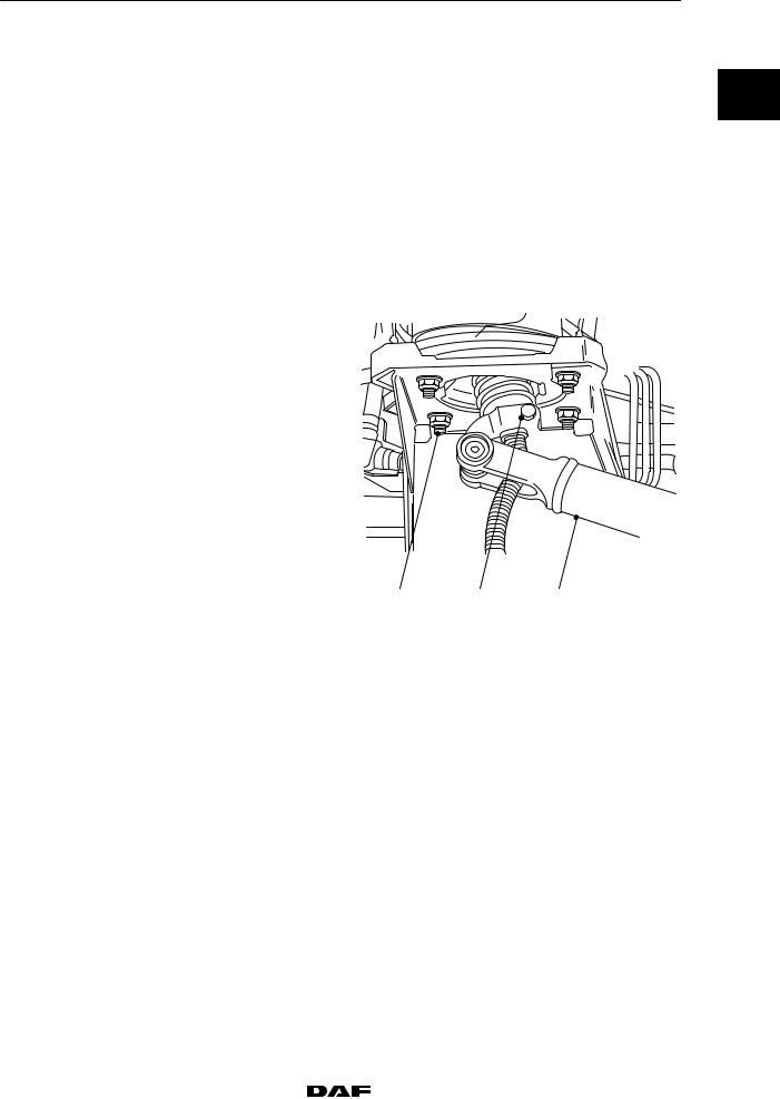
If the selector shaft lever has two attachment holes, the attachment hole (A) in the selector shaft lever should be used to attach the shaft lever properly to the control rod.
|
A |
|
V300833 |
Bonding the gear lever into the ball |
|
De-greaser |
DAF No. 1322827 |
Glue |
DAF No. 1340646 |
Bonding the ball joint to the control rod |
|
De-greaser |
DAF No. 1322827 |
Glue |
DAF No. 1340646 |
1-2 |
|
|
|
200337 |
|
https://www.truck-manuals.net/ |
|||||
|
|
||||
3 |
|
TECHNICAL DATA |
CF65/75/85 series |
|
Mechanical gearbox control |
1.2 TIGHTENING TORQUES |
|
|
The tightening torques stated in this section are |
0 |
|
different from the standard tightening torques |
|
|
included in the overview of standard tightening |
|
|
torques. |
|
|
Any other threaded connections that are |
|
|
not specified must therefore be tightened to the |
|
|
torque stated in the overview of |
|
|
standard tightening torques. |
|
|
When attachment bolts and nuts are to be |
|
|
replaced, it is important that they are of exactly |
|
|
the same length and property class as the ones |
|
|
removed unless stated otherwise. |
|
|
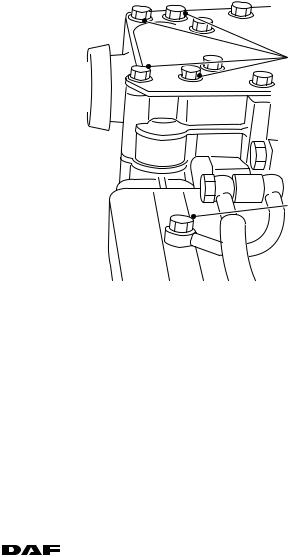
Control rod |
|
|
Fastening bolt (1) of control rod |
|
|
on gear lever unit |
40 Nm |
|
Attachment nuts (3), gear |
|
|
lever unit |
27 Nm |
|
Attachment bolt, selector shaft |
|
|
lever to gearbox selector |
|
|
housing |
40 Nm |
|
3 |
1 |
2 |
V300275
200337 |
|
|
|
1-3 |
|
https://www.truck-manuals.net/ |
|||||
|
|
||||

TECHNICAL DATA |
3 |
|
|
Mechanical gearbox control |
CF65/75/85 series |
0
1-4 |
|
|
|
200337 |
|
https://www.truck-manuals.net/ |
|||||
|
|
||||
3 |
TECHNICAL DATA |
|
|
|
|
|
|
CF65/75/85 series |
Pneumatically assisted gearbox control (Servoshift) |
|
|
2. PNEUMATICALLY ASSISTED GEARBOX CONTROL |
|
||
(SERVOSHIFT) |
0 |
||
2.1 GENERAL |
|
|
|
|
|
|
|
Servoshift unit |
|
|
|
Service pressure |
max. 10 bar |
|
|
2.2 TIGHTENING TORQUES
The tightening torques stated in this section are different from the standard tightening torques included in the overview of standard tightening torques.
Any other threaded connections that are
not specified must therefore be tightened to the torque stated in the overview of
standard tightening torques.
When attachment bolts and nuts are to be replaced, it is important that they are of exactly the same length and property class as the ones removed unless stated otherwise.
Air pipe banjo bolt (1) Attachment bolts: Servoshift unit (2)
38 Nm
23 Nm
2 |
1
V300328
200337 |
|
|
|
2-1 |
|
https://www.truck-manuals.net/ |
|||||
|
|
||||

TECHNICAL DATA |
3 |
|
|
Pneumatically assisted gearbox control (Servoshift) |
CF65/75/85 series |
0
2-2 |
|
|
|
200337 |
|
https://www.truck-manuals.net/ |
|||||
|
|
||||
3 |
TECHNICAL DATA |
||
|
|
|
|
CF65/75/85 series |
Pneumatic section of gearbox |
||
3. PNEUMATIC SECTION OF GEARBOX |
|
|
|
3.1 GENERAL |
|
|
0 |
|
|
|
|
|
|
|
|
If the vehicle is modified and the configuration changed, the electronic unit may have to be programmed.
Note:
If the vehicle’s drive configuration is changed, this must always be stated. The gate protection and range-change protection frequencies programmed into the electronic unit are related to the drive configuration.
GV VALVE |
|
|
|
GV valve begins to |
|
|
|
open (C) |
123 2 mm |
|
|
Total clutch pedal |
|
|
|
travel (D) |
154 2 mm |
|
|
NEUTRAL POSITION VALVE |
|
||
Situation with separate air distribution block: |
|
||
2 x 3/2-way valve |
|
A |
|
Service pressure |
6.5 to 10 bar |
||
Pipe connection |
M14 x 1.5 |
|
|
Situation with integrated air distribution |
|
||
block: |
|
|
|
3/2-way valve |
|
1 |
|
Service pressure |
6.5 to 10 bar |
||
|
|||
Pipe connection |
Not applicable |
|
|
B
C
D
V300315
200337 |
|
|
|
3-1 |
|
https://www.truck-manuals.net/ |
|||||
|
|
||||
|
TECHNICAL DATA |
3 |
|
|
Pneumatic section of gearbox |
CF65/75/85 series |
|
|
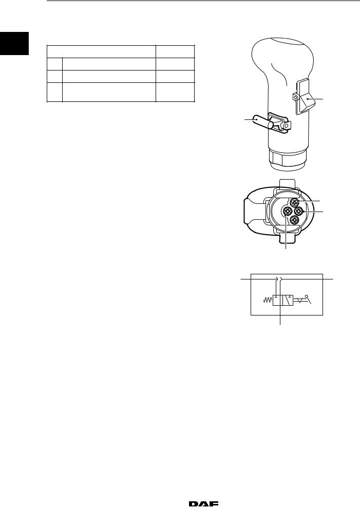
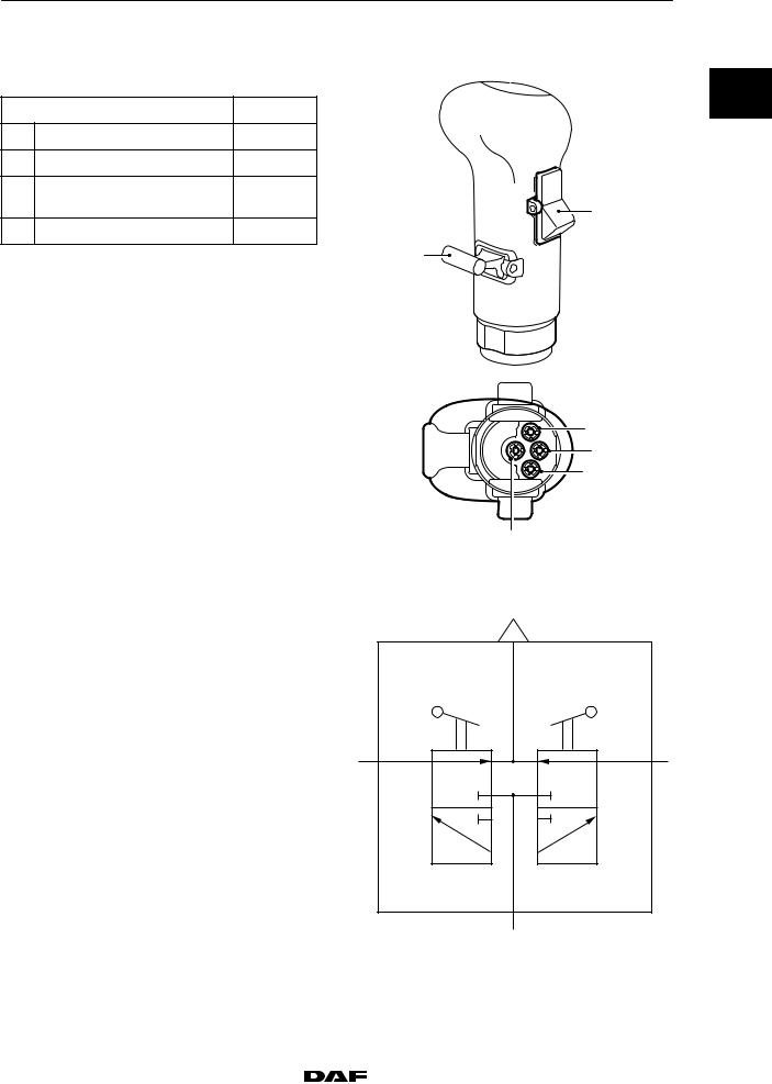
GEAR LEVER SELECTOR VALVE |
|
|
0 |
Range-change gear |
|
|
|
|
||
|
|
Connection point |
Colour |
|
1 |
Supply |
Black |
|
3 |
Bleed |
Red |
|
21 |
Range-change gear |
White |
|
|
command (A) |
B |
A
21
1
|
|
3 |
|
|
V300488 |
PNEUMATIC SYMBOL |
1 |
3 |
|
I |
I I |
|
|
Range |
|
|
21 |
|
|
V300267 |
3-2 |
|
|
|
200337 |
|
https://www.truck-manuals.net/ |
|||||
|
|
||||
3 |
|
TECHNICAL DATA |
CF65/75/85 series |
Pneumatic section of gearbox |
|
GEAR LEVER SELECTOR VALVE |
|
|
Range-change gear and splitter |
0 |
|
|
||
|
Connection point |
Colour |
1 |
Supply |
Black |
3 |
Bleed |
Red |
21 |
Range-change gear |
White |
|
command (A) |
B |
22 |
Splitter command (B) |
Yellow |
A
21
1
22
3
V300489
PNEUMATIC SYMBOL
Range-change gear and splitter
Position |
Function |
|
|
GP |
Range-change gear |
|
|
GV |
Splitter |
|
|
22
H
L
GV
21
H
L
GP
1
V300161
200337 |
|
|
|
3-3 |
|
https://www.truck-manuals.net/ |
|||||
|
|
||||

|
|
TECHNICAL DATA |
|
3 |
|
|
|
|
|
|
|
Pneumatic section of gearbox |
CF65/75/85 series |
|
|
|
3.2 TIGHTENING TORQUES |
|
|
|
|
|
|
|
0 |
|
The tightening torques stated in this section are |
|
|
|
|
different from the standard tightening torques |
|
|
|
|
included in the overview of standard tightening |
|
|
|
|
torques. |
|
|
|
|
Any other threaded connections that are |
|
|
|
|
not specified must therefore be tightened to the |
|
|
|
|
torque stated in the overview of |
|
|
|
|
standard tightening torques. |
|
|
|
|
When attachment bolts and nuts are to be |
|
|
|
|
replaced, it is important that they are of exactly |
|
|
|
|
the same length and property class as the ones |
|
|
|
|
removed unless stated otherwise. |
|
|
|
|
Gear button on gear lever |
|
|
|
|
Gear button lock nut |
70 Nm |
|
3-4 |
|
|
|
200337 |
|
https://www.truck-manuals.net/ |
|||||
|
|
||||

3 |
|
TECHNICAL DATA |
||
|
|
|
||
CF65/75/85 series |
ZF 6S-850 gearbox |
|||
4. |
ZF 6S-850 GEARBOX |
|
|
|
4.1 |
GENERAL |
|
|
0 |
|
|
|
|
|
|
|
|
|
|
Gearbox type
Each gearbox has a type-plate attached to it, indicating the type of gearbox. This data is also stated on the identity card of the relevant vehicle.
ZF gearbox type-plate
1.Type of gearbox
2. |
Series no. (ZF) |
1 |
3. |
Parts list (ZF) |
|
4.Specification no.
5. |
Pulse generator ratio |
3 |
|
|
|
|
|
|
|
|
|
|
|
|
|
|
|
|
2 |
|
|
|
|
|
|
|
|
|
|
|
|
|
|
|
|
|
|||||
6. |
Gearbox ratio |
|
|
|
|
|
|
|
|
|
|
|
|
|
|
|
|
|
|
4 |
|
|
|
|
|
|
|
|
|
|
|
|
|
|
|
|
|
|
|||
7. |
Engine speed using PTO |
6 |
|
|
|
|
|
|
|
|
|
|
|
|
|
|
|
|
||
|
|
|
|
|
|
|
|
|
|
|
|
|
|
|
|
|
5 |
|||
8. |
PTO speed |
|
|
|
|
|
|
|
|
|
|
|
|
|
|
|
|
|||
|
|
|
|
|
|
|
|
|
|
|
|
|
|
|
|
|||||
9. |
Gearbox oil capacity |
8 |
|
|
|
|
|
|
|
|
|
|
|
|
|
|
|
|
|
7 |
|
|
|
|
|
|
|
|
|
|
|
|
|
|
|
|
|
||||
10. |
Oil specification |
|
|
|
|
|
|
|
|
|
|
|
|
|
|
|||||
|
|
|
|
|
|
|
|
|
|
|
|
|
|
|
|
|
|
|
||
|
|
|
|
|
|
|
|
|
|
|
|
|
|
|
|
|
|
|
|
|
|
|
|
|
|
|
|
|
|
|
|
|
|
|
|
|
|
|
|
|
|
|
|
|
|
|
|
|
|
|
|
|
|
|
|
|||||||
|
|
9 |
|
|
10 |
|
|
|
|
|||||||||||
|
|
|
|
|
|
|
|
|
|
|
|
|
|
|
|
|
|
V300049 |
||
Output shaft bearing axial play |
|
|
|
|
|
|
|
|
|
|
|
|
|
|
|
|
|
|
|
|
Output shaft bearing axial play |
0.00 - 0.10 mm |
|
|
|
|
|
|
|
|
|
||||||||||
Bearing axial play, main and input shafts |
|
|
|
|
|
|
|
|
|
|
|
|
|
|
|
|
|
|
|
|
Bearing axial play, main and input shafts |
0.00 - 0.10 mm |
|
|
|
|
|
|
|
|
|
||||||||||
Auxiliary shaft bearing axial play |
|
|
|
|
|
|
|
|
|
|
|
|
|
|
|
|
|
|
|
|
Auxiliary shaft bearing axial play |
0.00 - 0.10 mm |
|
|
|
|
|
|
|
|
|
||||||||||
200337 |
|
|
|
4-1 |
|
https://www.truck-manuals.net/ |
|||||
|
|
||||

|
|
TECHNICAL DATA |
3 |
|
|
|
|
|
|
ZF 6S-850 gearbox |
CF65/75/85 series |
|
|
4.2 TIGHTENING TORQUES |
|
|
|
|
|
0 |
|
The tightening torques stated in this section are |
|
|
|
different from the standard tightening torques |
|
|
|
included in the overview of standard tightening |
|
|
|
torques. |
|
|
|
Any other threaded connections that are |
|
|
|
not specified must therefore be tightened to the |
|
|
|
torque stated in the overview of |
|
|
|
standard tightening torques. |
|
|
|
When attachment bolts and nuts are to be |
|
|
|
replaced, it is important that they are of exactly |
|
|
|
the same length and property class as the ones |
|
|
|
removed unless stated otherwise. |
|
|
|
Gearbox to engine |
|
|
|
M8 attachment bolts - 10.9 |
30 Nm |
|
|
M10 attachment bolts - 10.9 |
60 Nm |
|
|
M12 attachment bolts - 10.9 |
110 Nm |
|
|
Drive flange |
|
|
|
Drive flange attachment bolt |
|
|
|
- 120 mm flange diameter |
140 Nm |
|
|
- 150 mm flange diameter |
140 Nm |
|
|
Gearbox front cover |
|
|
|
Attachment bolts |
23 Nm |
|
|
Selector shaft housing |
|
|
|
Attachment bolts |
23 Nm |
|
|
Shifting arm lock nut |
46 Nm |
|
|
Air connection banjo bolt |
23 Nm |
|
|
Bleeder |
10 Nm |
|
|
Plugs |
|
|
|
Drain plug |
50 Nm |
|
|
Level check/filler plug |
50 Nm |
4.3 FILLING CAPACITIES
Gearbox type |
Filling capacities at oil change |
First filling, e.g. during repair |
|
(litres) |
(litres) |
|
|
|
ZF 6S-850 |
7.5 |
7.5 |
|
|
|
4-2 |
|
|
|
200337 |
|
https://www.truck-manuals.net/ |
|||||
|
|
||||
3 |
|
TECHNICAL DATA |
||
|
|
|
||
CF65/75/85 series |
ZF 8/9/16S-109 gearbox |
|||
5. |
ZF 8/9/16S-109 GEARBOX |
|
|
|
5.1 |
GENERAL |
|
|
0 |
|
|
|
|
|
|
|
|
|
|
Gearbox type
Each gearbox has a type-plate attached to it, indicating the type of gearbox. This data is also stated on the identity card of the relevant vehicle.
ZF gearbox type-plate
1.Type of gearbox
2. |
Series no. (ZF) |
1 |
3. |
Parts list (ZF) |
|
4.Specification no.
5. |
Pulse generator ratio |
3 |
|
|
|
|
|
|
|
|
|
|
|
|
|
|
|
|
2 |
|
|
|
|
|
|
|
|
|
|
|
|
|
|
|
|
|
|||||
6. |
Gearbox ratio |
|
|
|
|
|
|
|
|
|
|
|
|
|
|
|
|
|
|
4 |
|
|
|
|
|
|
|
|
|
|
|
|
|
|
|
|
|
|
|||
7. |
Engine speed using PTO |
6 |
|
|
|
|
|
|
|
|
|
|
|
|
|
|
|
|
||
|
|
|
|
|
|
|
|
|
|
|
|
|
|
|
|
|
5 |
|||
8. |
PTO speed |
|
|
|
|
|
|
|
|
|
|
|
|
|
|
|
|
|||
|
|
|
|
|
|
|
|
|
|
|
|
|
|
|
|
|||||
9. |
Gearbox oil capacity |
8 |
|
|
|
|
|
|
|
|
|
|
|
|
|
|
|
|
|
7 |
|
|
|
|
|
|
|
|
|
|
|
|
|
|
|
|
|
||||
10. |
Oil specification |
|
|
|
|
|
|
|
|
|
|
|
|
|
|
|||||
|
|
|
|
|
|
|
|
|
|
|
|
|
|
|
|
|
|
|
||
|
|
|
|
|
|
|
|
|
|
|
|
|
|
|
|
|
|
|
|
|
|
|
|
|
|
|
|
|
|
|
|
|
|
|
|
|
|
|
|
|
|
|
|
|
|
|
|
|
|
|
|
|
|
|
|
|||||||
|
|
9 |
|
|
10 |
|
|
|
|
|||||||||||
|
|
|
|
|
|
|
|
|
|
|
|
|
|
|
|
|
|
V300049 |
||
Output shaft bearing axial play |
|
|
|
|
|
|
|
|
|
|
|
|
|
|
|
|
|
|
|
|
Output shaft bearing axial play |
0.00 - 0.10 mm |
|
|
|
|
|
|
|
|
|
||||||||||
Bearing axial pre-load, main and |
|
|
|
|
|
|
|
|
|
|
|
|
|
|
|
|
|
|
|
|
input shafts |
|
|
|
|
|
|
|
|
|
|
|
|
|
|
|
|
|
|
|
|
Bearing axial pre-load, main and input shafts |
|
|
|
|
|
|
|
|
|
|
|
|
|
|
|
|
|
|
|
|
8/9S-109 |
0.18 - 0.30 mm |
|
|
|
|
|
|
|
|
|
||||||||||
16S-109 |
0.18 - 0.30 mm |
|
|
|
|
|
|
|
|
|
||||||||||
Bearing axial pre-load, auxiliary shaft |
|
|
|
|
|
|
|
|
|
|
|
|
|
|
|
|
|
|
|
|
Bearing axial pre-load, auxiliary shaft |
|
|
|
|
|
|
|
|
|
|
|
|
|
|
|
|
|
|
|
|
8/9S-109 |
0.18 - 0.30 mm |
|
|
|
|
|
|
|
|
|
||||||||||
16S-109 |
0.18 - 0.30 mm |
|
|
|
|
|
|
|
|
|
||||||||||
Retaining element |
|
|
|
|
|
|
|
|
|
|
|
|
|
|
|
|
|
|
|
|
Standard spring force |
168 N |
|
|
|
|
|
|
|
|
|
||||||||||
Heavy-duty spring force |
191 N |
|
|
|
|
|
|
|
|
|
||||||||||
200337 |
|
|
|
5-1 |
|
https://www.truck-manuals.net/ |
|||||
|
|
||||

|
|
TECHNICAL DATA |
3 |
|
|
|
|
|
|
ZF 8/9/16S-109 gearbox |
CF65/75/85 series |
|
|
5.2 TIGHTENING TORQUES |
|
|
|
|
|
0 |
|
The tightening torques stated in this section are |
|
|
|
different from the standard tightening torques |
|
|
|
included in the overview of standard tightening |
|
|
|
torques. |
|
|
|
Any other threaded connections that are |
|
|
|
not specified must therefore be tightened to the |
|
|
|
torque stated in the overview of |
|
|
|
standard tightening torques. |
|
|
|
When attachment bolts and nuts are to be |
|
|
|
replaced, it is important that they are of exactly |
|
|
|
the same length and property class as the ones |
|
|
|
removed unless stated otherwise. |
|
|
|
Gearbox to engine |
|
|
|
M8 attachment bolts - 10.9 |
30 Nm |
|
|
M10 attachment bolts - 10.9 |
60 Nm |
|
|
M12 attachment bolts - 10.9 |
110 Nm |
|
|
Drive flange |
|
|
|
Retaining plate attachment bolts |
60 Nm |
|
|
Gearbox front cover |
|
|
|
Attachment bolts |
25 Nm |
|
|
Bearing cover |
|
|
|
Output shaft bearing cover |
25 Nm |
|
|
Control bearing cover |
25 Nm |
|
|
Air connection banjo bolt |
38 Nm |
|
|
Shift control high/low |
|
|
|
Shifting fork high/low bolts |
180 Nm |
|
|
Gear engaging cylinder piston lock nut |
180 Nm |
|
|
Gear engaging cylinder attachment bolts |
50 Nm |
|
|
Air connection banjo bolt |
38 Nm |
|
|
Rear gearbox cover attachment bolts |
50 Nm |
|
|
Plugs |
|
|
|
M24 drain plug |
60 Nm |
|
|
M38 drain plug |
120 Nm |
|
|
Level check/filler plug |
60 Nm |
5-2 |
|
|
|
200337 |
|
https://www.truck-manuals.net/ |
|||||
|
|
||||
3 |
|
|
TECHNICAL DATA |
CF65/75/85 series |
ZF 8/9/16S-109 gearbox |
||
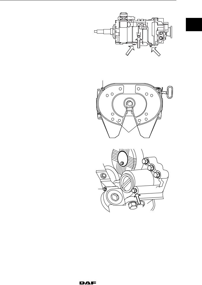
Plugs |
|
|
|
Gearbox with integrated intarder |
|
0 |
|
Drain plug (B) |
M24 |
60 Nm |
|
Drain plug (B) |
M38 |
120 Nm |
|
Drain plug (C) |
|
60 Nm |
|
Level check/filler plug (A). |
60 Nm |
|
|
Oil filter attachment bolt (1) |
23 Nm |
|
|
|
|
B |
A |
|
|
B |
|
|
|
|
M3017 |
2
1
V300372
 1
1 
M3052
200337 |
|
|
|
5-3 |
|
https://www.truck-manuals.net/ |
|||||
|
|
||||

|
|
TECHNICAL DATA |
|
3 |
|
|
|
|
|
|
|
|
|
ZF 8/9/16S-109 gearbox |
|
CF65/75/85 series |
|
|
|
5.3 FILLING CAPACITIES |
|
|
|
|
|
|
|
|
|
0 |
|
Filling amounts, ZF gearboxes without |
|
|
|
|
|
intarder |
|
|
|
|
|
|
|
|
|
|
|
Gearbox type |
Filling amounts at oil change |
First filling, e.g. during repair |
|
|
|
|
(litres) |
(litres) |
|
|
|
|
|
|
|
|
|
ZF 8/16S-109 |
9 |
9.5 |
|
|
|
|
|
|
|
|
|
ZF 9/S-109 |
8 |
8.5 |
|
|
|
|
|
|
|
|
|
Filling amounts, ZF gearboxes with |
|
|
|
|
|
integrated intarder |
|
|
|
|
|
|
|
|
|
|
|
Gearbox type |
Filling amounts at oil change |
First filling, e.g. during repair |
|
|
|
|
(litres) |
(litres) |
|
|
|
|
|
|
|
|
|
ZF 8/16S-109 |
12.5 |
22 |
|
|
|
|
|
|
|
|
|
ZF 9S-109 |
12 |
21 |
|
|
|
|
|
|
|
5-4 |
|
|
|
200337 |
|
https://www.truck-manuals.net/ |
|||||
|
|
||||
3 |
TECHNICAL DATA |
|
|
|
|
CF65/75/85 series |
ZF 8/16S-151/181 and 16S-221 gearboxes |
|
6. ZF 8/16S-151/181 AND 16S-221 GEARBOXES |
|
6.1 GENERAL |
0 |
|
|
Gearbox type |
|
|
|
Each gearbox has a type-plate attached to it, |
|
indicating the type of gearbox. This data is also |
|
stated on the identity card of the relevant |
|
vehicle. |
|
ZF gearbox type-plate
1.Type of gearbox
2. |
Series no. (ZF) |
1 |
3. |
Parts list (ZF) |
|
4.Specification no.
5. |
Pulse generator ratio |
3 |
|
|
|
|
|
|
|
|
|
|
|
|
|
|
|
|
2 |
|
|
|
|
|
|
|
|
|
|
|
|
|
|
|
|
|
|||||
6. |
Gearbox ratio |
|
|
|
|
|
|
|
|
|
|
|
|
|
|
|
|
|
|
4 |
|
|
|
|
|
|
|
|
|
|
|
|
|
|
|
|
|
|
|||
7. |
Engine speed using PTO |
6 |
|
|
|
|
|
|
|
|
|
|
|
|
|
|
|
|
||
|
|
|
|
|
|
|
|
|
|
|
|
|
|
|
|
|
5 |
|||
8. |
PTO speed |
|
|
|
|
|
|
|
|
|
|
|
|
|
|
|
|
|||
|
|
|
|
|
|
|
|
|
|
|
|
|
|
|
|
|||||
9. |
Gearbox oil capacity |
8 |
|
|
|
|
|
|
|
|
|
|
|
|
|
|
|
|
|
7 |
|
|
|
|
|
|
|
|
|
|
|
|
|
|
|
|
|
||||
10. |
Oil specification |
|
|
|
|
|
|
|
|
|
|
|
|
|
|
|||||
|
|
|
|
|
|
|
|
|
|
|
|
|
|
|
|
|
|
|
||
|
|
|
|
|
|
|
|
|
|
|
|
|
|
|
|
|
|
|
|
|
|
|
|
|
|
|
|
|
|
|
|
|
|
|
|
|
|
|
|
|
|
|
|
|
|
|
|
|
|
|
|
|
|
|
|
|||||||
|
|
9 |
|
|
10 |
|
|
|
|
|||||||||||
|
|
|
|
|
|
|
|
|
|
|
|
|
|
|
|
|
|
V300049 |
||
Output shaft bearing axial play |
|
|
|
|
|
|
|
|
|
|
|
|
|
|
|
|
|
|
|
|
Output shaft bearing axial play |
0.00 - 0.10 mm |
|
|
|
|
|
|
|
|
|
||||||||||
Bearing axial play, main and input shafts |
|
|
|
|
|
|
|
|
|
|
|
|
|
|
|
|
|
|
|
|
Bearing axial play, main and input shafts |
0.00 - 0.10 mm |
|
|
|
|
|
|
|
|
|
||||||||||
Auxiliary shaft bearing axial play |
|
|
|
|
|
|
|
|
|
|
|
|
|
|
|
|
|
|
|
|
Auxiliary shaft bearing axial play |
0.00 - 0.10 mm |
|
|
|
|
|
|
|
|
|
||||||||||
Retaining element |
|
|
|
|
|
|
|
|
|
|
|
|
|
|
|
|
|
|
|
|
Standard spring force |
168 N |
|
|
|
|
|
|
|
|
|
||||||||||
Heavy-duty spring force |
191 N |
|
|
|
|
|
|
|
|
|
||||||||||
200337 |
|
|
|
6-1 |
|
https://www.truck-manuals.net/ |
|||||
|
|
||||

|
|
TECHNICAL DATA |
3 |
|
|
|
|
|
|
ZF 8/16S-151/181 and 16S-221 gearboxes |
CF65/75/85 series |
|
|
6.2 TIGHTENING TORQUES |
|
|
|
|
|
0 |
|
The tightening torques stated in this section are |
|
|
|
different from the standard tightening torques |
|
|
|
included in the overview of standard tightening |
|
|
|
torques. |
|
|
|
Any other threaded connections that are |
|
|
|
not specified must therefore be tightened to the |
|
|
|
torque stated in the overview of |
|
|
|
standard tightening torques. |
|
|
|
When attachment bolts and nuts are to be |
|
|
|
replaced, it is important that they are of exactly |
|
|
|
the same length and property class as the ones |
|
|
|
removed unless stated otherwise. |
|
|
|
Gearbox to engine |
|
|
|
M8 attachment bolts - 10.9 |
30 Nm |
|
|
M10 attachment bolts - 10.9 |
60 Nm |
|
|
M12 attachment bolts - 10.9 |
110 Nm |
|
|
Drive flange |
|
|
|
M12 x 70 drive flange - 8.8 |
60 Nm |
|
|
M12 x 60 drive flange - 10.9 |
120 Nm |
|
|
M12 x 70 drive flange - 10.9 |
120 Nm |
|
|
M12 x 165 drive flange - 10.9 |
120 Nm |
|
|
Gearbox front cover |
|
|
|
Attachment bolts |
46 Nm |
|
|
Bearing cover |
|
|
|
Output shaft bearing cover |
49 Nm |
|
|
Control bearing cover |
23 Nm |
|
|
Shift control high/low |
|
|
|
Shifting fork high/low bolts |
180 Nm |
|
|
Gear engaging cylinder piston lock nut |
180 Nm |
|
|
Gear engaging cylinder attachment bolts |
50 Nm |
|
|
Air connection banjo bolt |
38 Nm |
|
|
Rear gearbox cover attachment bolts |
50 Nm |
|
|
Plugs |
|
|
|
M24 drain plug |
60 Nm |
|
|
M38 drain plug |
120 Nm |
|
|
Level check/filler plug |
60 Nm |
6-2 |
|
|
|
200337 |
|
https://www.truck-manuals.net/ |
|||||
|
|
||||
3 |
TECHNICAL DATA |
CF65/75/85 series
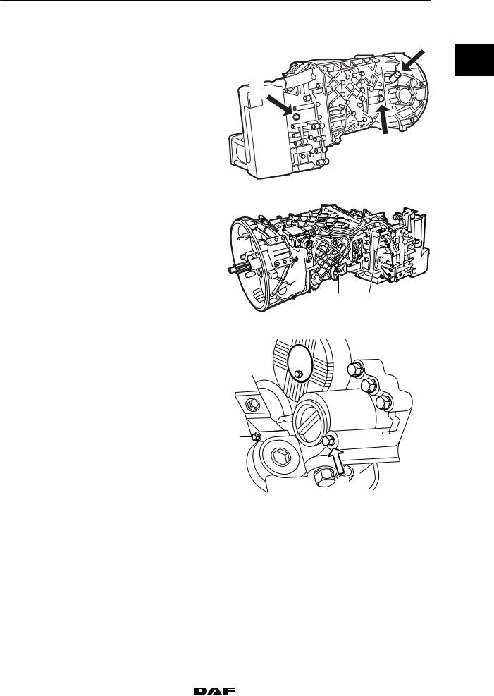
Plugs |
|
|
Gearbox with integrated intarder |
|
|
Drain plug (B) |
M24 |
60 Nm |
Drain plug (B) |
M38 |
120 Nm |
Drain plug (D) |
|
60 Nm |
Level check/filler plug (4) |
60 Nm |
|
Filler plug (5) |
|
60 Nm |
Oil filter attachment bolt (1) |
23 Nm |
|
ZF 8/16S-151/181 and 16S-221 gearboxes
B
0
D
C
V300186
4 5
V300260
 1
1 
M3052
200337 |
|
|
|
6-3 |
|
https://www.truck-manuals.net/ |
|||||
|
|
||||

|
|
TECHNICAL DATA |
|
3 |
|
|
|
|
|
|
|
|
|
ZF 8/16S-151/181 and 16S-221 gearboxes |
CF65/75/85 series |
|
|
|
|
6.3 FILLING CAPACITIES |
|
|
|
|
|
|
|
|
|
0 |
|
Filling amounts, ZF gearboxes without |
|
|
|
|
|
intarder |
|
|
|
|
|
|
|
|
|
|
|
Gearbox type |
Filling amounts at oil change |
First filling, e.g. during repair |
|
|
|
|
(litres) |
(litres) |
|
|
|
|
|
|
|
|
|
ZF 8/16S-151 |
11 |
11 |
|
|
|
|
|
|
|
|
|
ZF 8/16S-181 |
13 |
13 |
|
|
|
|
|
|
|
|
|
ZF 16S-221 |
13 |
13 |
|
|
|
|
|
|
|
|
|
Filling amounts, ZF gearboxes with |
|
|
|
|
|
integrated intarder |
|
|
|
|
|
|
|
|
|
|
|
Gearbox type |
Filling amounts at oil change |
First filling, e.g. during repair |
|
|
|
|
(litres) |
(litres) |
|
|
|
|
|
|
|
|
|
ZF 8/16S-151 |
11 |
18.5 |
|
|
|
|
|
|
|
|
|
ZF 8/16S-181 |
12 |
21.5 |
|
|
|
|
|
|
|
|
|
ZF 16S-221 |
12 |
21.5 |
|
|
|
|
|
|
|
6-4 |
|
|
|
200337 |
|
https://www.truck-manuals.net/ |
|||||
|
|
||||

3 |
|
TECHNICAL DATA |
||
|
|
|
||
CF65/75/85 series |
Eaton FS/6309A gearbox |
|||
7. |
EATON FS/6309A GEARBOX |
|
|
|
7.1 |
GENERAL |
|
|
0 |
|
|
|
|
|
|
|
|
|
|
Gearbox type
Each gearbox has a type-plate attached to it, indicating the type of gearbox. This data is also stated on the identity card of the relevant vehicle.
Eaton gearbox type-plate
1.Type of gearbox
2.Specification no. Eaton
3.DAF article Eaton code
4.Series no. Eaton
5.Production date code
The Eaton specification number is unique for each customer and gives detailed information on the development level of the gearbox.
The number must be quoted whenever replacement parts are ordered.
Input shaft play adjusting rings:
3.70 mm
3.75 mm
3.80 mm
3.85 mm
3.90 mm
3.95 mm
Secondary shaft pre-load
New bearings
Original bearings
Sealant
Sealing compound for seal contact surfaces of drive flange oil seal housing
Input shaft
Filter/governor
Governed pressure
Colour coding:
Red, green, white
Yellow, green, blue
Blue, green, white
Red, green, yellow
Green, green, white
Red, green, red
0.075 - 0.125 mm
0.000 - 0.050 mm
Loctite 518
Lithium-based grease, class NLGI 3
5.3 - 5.7 bar
200337 |
|
|
|
7-1 |
|
https://www.truck-manuals.net/ |
|||||
|
|
||||

|
|
TECHNICAL DATA |
|
3 |
|
|
|
|
|
|
|
Eaton FS/6309A gearbox |
|
CF65/75/85 series |
|
|
7.2 TIGHTENING TORQUES |
|
|
|
|
|
|
|
0 |
|
The tightening torques stated in this section are |
|
|
|
|
different from the standard tightening torques |
|
|
|
|
included in the overview of standard tightening |
|
|
|
|
torques. |
|
|
|
|
Any other threaded connections that are |
|
|
|
|
not specified must therefore be tightened to the |
|
|
|
|
torque stated in the overview of |
|
|
|
|
standard tightening torques. |
|
|
|
|
When attachment bolts and nuts are to be |
|
|
|
|
replaced, it is important that they are of exactly |
|
|
|
|
the same length and property class as the ones |
|
|
|
|
removed unless stated otherwise. |
|
|
|
|
Drive flange |
|
|
|
|
M39 drive flange nut |
650 Nm(1) |
|
|
|
Drive flange oil seal housing attachment bolts |
60 |
Nm |
|
|
Gearbox front cover |
|
|
|
|
Attachment bolts |
37 |
Nm |
|
|
Selector shaft housing |
|
|
|
|
Selector shaft housing attachment bolts |
37 |
Nm(2) |
|
|
Retaining cover attachment bolts |
22 |
Nm |
|
|
M8 shifting arm lock nut |
25 |
Nm |
|
|
M8 shifting arm lock nut |
25 |
Nm |
|
|
End cover attachment bolts |
22 |
Nm |
|
|
Bleed valve |
|
|
|
|
Attachment bolts |
19 |
Nm |
|
|
Bearing cover |
|
|
|
|
Output shaft bearing cover |
25 |
Nm |
|
|
Air connection banjo bolt |
38 |
Nm |
|
|
Filter/governor |
|
|
|
|
M6 attachment bolts |
13 |
Nm |
|
|
Cover |
25 Nm |
|
|
|
Selector valve |
|
|
|
|
M6 attachment bolts |
22 |
Nm |
|
|
M16 discharge valve attachment bolts |
19 |
Nm |
|
|
M8 cover plate attachment bolts |
22 |
Nm |
|
|
Range-change cylinder |
|
|
|
|
M8 cover plate attachment bolts |
17 |
Nm |
|
|
M16 nut on piston |
105 Nm |
|
7-2 |
|
|
|
200337 |
|
https://www.truck-manuals.net/ |
|||||
|
|
||||

3 |
|
TECHNICAL DATA |
||
|
|
|
|
|
CF65/75/85 series |
|
Eaton FS/6309A gearbox |
||
Plugs |
|
|
|
|
Drain plug |
50 Nm |
|
|
|
|
|
0 |
||
Level check/filler plug |
50 Nm |
|
|
|
|
|
|
|
|
(1)Use new nut
(2)Loctite 243
7.3 FILLING CAPACITIES
Gearbox capacity
Type |
Contents |
|
|
FS/6309A |
8.5 litres |
|
|
200337 |
|
|
|
7-3 |
|
https://www.truck-manuals.net/ |
|||||
|
|
||||

TECHNICAL DATA |
3 |
|
|
Eaton FS/6309A gearbox |
CF65/75/85 series |
0
7-4 |
|
|
|
200337 |
|
https://www.truck-manuals.net/ |
|||||
|
|
||||

3 |
|
TECHNICAL DATA |
||
|
|
|
||
CF65/75/85 series |
Allison automatic gearbox |
|||
8. |
ALLISON AUTOMATIC GEARBOX |
|
|
|
8.1 |
GENERAL |
|
|
0 |
|
|
|
|
|
|
|
|
|
|
Allison transmission, used in the CF65/75, is electronically controlled and has its own diagnostic system that saves any faults in the memory of the ECU (Electronic Control Unit). The faults can be read at a later date. The system is operated and the faults are read via the selector keypad. The “Selector keypad” fitted with a display is located next to the driver’s seat and replaces the gear lever with manual stick-shift gearboxes.
R MODE
N
D
V300392
200337 |
|
|
|
8-1 |
|
https://www.truck-manuals.net/ |
|||||
|
|
||||

|
|
TECHNICAL DATA |
3 |
|
|
|
|
|
|
Allison automatic gearbox |
CF65/75/85 series |
|
|
8.2 TIGHTENING TORQUES |
|
|
|
|
|
0 |
|
The tightening torques stated in this section are |
|
|
|
different from the standard tightening torques |
|
|
|
included in the overview of standard tightening |
|
|
|
torques. |
|
|
|
Any other threaded connections that are |
|
|
|
not specified must therefore be tightened to the |
|
|
|
torque stated in the overview of |
|
|
|
standard tightening torques. |
|
|
|
When attachment bolts and nuts are to be |
|
|
|
replaced, it is important that they are of exactly |
|
|
|
the same length and property class as the ones |
|
|
|
removed unless stated otherwise. |
|
|
|
Gearbox bleeder |
14 Nm |
|
|
M14 x 2.0 drive flange attachment bolt |
75 Nm |
|
|
Gearbox rear mounting bracket |
100 Nm |
|
|
PTO bracket |
55 Nm |
|
|
Gearbox with flywheel housing adapter, M10 x |
|
|
1.5 |
55 Nm |
|
|
|
Flex plates to flex plate adapter |
|
|
|
CF65 |
68 Nm |
|
|
CF75 |
34 Nm |
|
|
Flex plate adapter to torque converter |
34 Nm |
|
Hydraulic pipes to oil cooler |
60 Nm |
|
|
|
Gearbox main connector |
2.5 Nm |
|
|
Attachment bolts for oil filter caps |
55 Nm |
|
|
Oil drain plugs |
28 Nm |
|
|
Coolant pipe attachment |
55 Nm |
|
|
Molycote for the top bearing of the torque |
|
|
|
converter on installation |
BR2S or BR2 Plus |
8-2 |
|
|
|
200337 |
|
https://www.truck-manuals.net/ |
|||||
|
|
||||
 Loading...