


 Loading...
6 |
STRUCTURE |
ΧΦ65/75/85 series
TECHNICAL DATA
DIAGNOSTICS
BRAKE DIAGRAMS FOR THE FULLY PNEUMATIC BRAKE SYSTEM
EBS BRAKE SYSTEM BRAKE DIAGRAMS
OPERATION OF BRAKE COMPONENTS
BRAKE SYSTEM AND COMPONENTS
BRAKING PERFORMANCE AND BRAKE EQUALISATION
0
1
2
3
4
5
6
© 200423 |
DW23241603 |
https://www.truck-manuals.net/
https://www.truck-manuals.net/

6 |
TECHNICAL DATA |
|
|
||
|
|
|
|
|
|
ΧΦ65/75/85 series |
|
Contents |
|
|
|
CONTENTS |
|
|
|
|
|
Page |
Date |
|
0 |
||
|
|
|
|||
1. BRAKE SYSTEM AND COMPONENTS |
1-1 |
200423 |
|
|
|
|
|
||||
1.1 |
General . . . . . . . . . . . . . . . . . . . . . . . . . . . . . . . . . . . . . . . . . . . . . . . . . . |
1-1 . . . . |
. 200423 |
|
|
1.2 |
Tightening torques. . . . . . . . . . . . . . . . . . . . . . . . . . . . . . . . . . . . . . . . . . . |
1-16 . . . |
. 200423 |
|
|
1.3 |
Lubricants . . . . . . . . . . . . . . . . . . . . . . . . . . . . . . . . . . . . . . . . . . . . . . . . |
1-19 . . . |
. 200423 |
|
|
2. BRAKING PERFORMANCE AND BRAKE EQUALISATION . . . . . . . . . . . . . . |
2-1 . . . . |
. 200423 |
|
|
|
2.1 |
General . . . . . . . . . . . . . . . . . . . . . . . . . . . . . . . . . . . . . . . . . . . . . . . . . . |
2-1 . . . . |
. 200423 |
|
|
© 200423 |
1 |
https://www.truck-manuals.net/

TECHNICAL DATA |
6 |
|
|
Contents |
ΧΦ65/75/85 series |
0
2 |
© 200423 |
https://www.truck-manuals.net/

6 |
TECHNICAL DATA |
||
|
|
|
|
ΧΦ65/75/85 series |
Brake system and components |
||
1. BRAKE SYSTEM AND COMPONENTS |
|
|
|
|
|
0 |
|
1.1 GENERAL |
|
||
|
|
|
|
|
|
|
|
Coding of components
All components have been provided with number codes.
Structure of the code
First digit
Where one connection performs several functions, additional 1st digits will be allocated. These are separated by a hyphen.
Often used:
1energy supply (pressure)
2energy discharge (outgoing command)
3bleeding
4control connection (incoming command)
Little used:
0 suction connection
5vacant
6vacant
7anti-freeze connection
8lubricating oil connection
9coolant connection
Second digit
If there are several connections with the same function, a 2nd digit will be added immediately after the 1st one.
Application example: empty/load relay valve
Meaning:
1air compressor energy supply
2energy discharge (command) to the next component
41control connection (incoming)
42second control connection (incoming)
© 200423 |
1-1 |
https://www.truck-manuals.net/

|
|
TECHNICAL DATA |
6 |
|
|
|
|
|
|
Brake system and components |
ΧΦ65/75/85 series |
|
|
Compressor |
|
0 |
|
|
|
|
CF65 series |
|
|
|
|
|
|
|
|
Type |
|
|
|
Make: |
Knorr SWC 9057 |
|
|
Version: |
1 cylinder, water cooled, 255 cc |
|
|
CF75/85 series |
|
|
|
Type |
|
|
|
Make: |
Wabco 911 504 ... |
|
|
Version: |
2 cylinder, water cooled |
|
|
Rejection sizes Wabco 911 504 ... compressor |
|
|
|
Cylinder bore at the turning point of the |
|
|
|
first piston ring |
75.022 mm |
|
|
Height of piston ring groove: |
|
|
|
first groove: |
2.035 mm |
|
|
second groove: |
2.035 mm |
|
|
third groove: |
4.047 mm |
|
|
Gudgeon pin hole diameter: |
15.018 mm |
|
|
Gudgeon pin diameter: |
14.992 mm |
|
|
Piston diameter, measured along the length of |
|
|
|
the piston pen on the underside of the piston skirt. |
74.962 mm |
|
|
Gudgeon pin bearing in connecting rod: |
15.047 mm |
|
|
Crankshaft bearing diameter, non-drive side: |
35.070 mm |
|
|
Crankshaft main bearing, non-drive side: |
34.963 mm |
|
|
Crankshaft diameter at the connecting rod: |
32.963 mm |
|
|
Always replace rolling bearing on drive side |
|
1-2 |
© 200423 |
https://www.truck-manuals.net/
6 |
TECHNICAL DATA |
|
|
ΧΦ65/75/85 series |
Brake system and components |
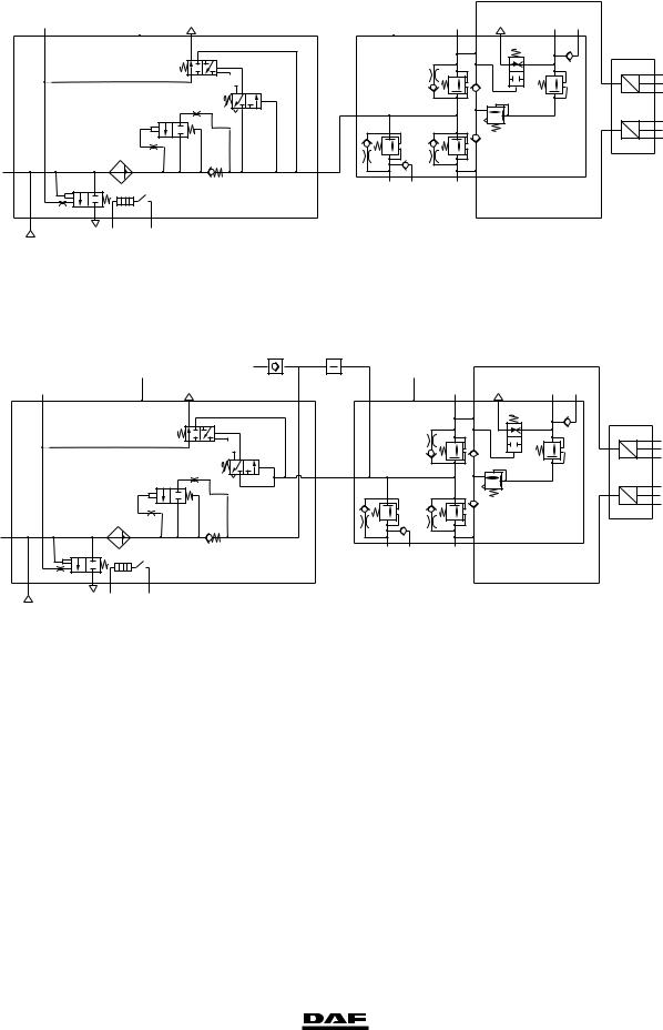
Air supply unit
23
1
E
12 3
C
<![if ! IE]><![endif]>6.1
A |
B |
|
|
0 |
||
|
|
|
21 |
3 |
23 25 |
|
|
|
|
|
|
|
|
|
|
H |
|
M |
|
|
|
|
D |
|
|
|
P U |
6.2 |
|
|
|
|
|
6.3 |
|||
|
1 |
|
|
L |
P |
6.4 |
|
F |
|
|
|
||||
|
|
|
6.5 |
||||
N |
J |
K |
|
|
U |
||
|
|
|
|||||
|
|
P |
6.6 |
||||
|
|
|
|
|
|
6.7 |
|
|
|
|
|
|
|
|
|
|
21 |
|
|
|
|
|
|
0 |
24 26 |
22 |
G
<![if ! IE]><![endif]>6.2
R600702
Knorr ZB4545 - II38005F, ZB4578 - K000394, ZB4580 - K000396 versions (used on front-axle leaf suspension)
23
1
12
E
3
C
<![if ! IE]><![endif]>6.1
2 R 1 |
1 Q 2 |
B |
|
|
|
|
|
A |
|
21 |
3 |
23 25 |
|
|
|
|
29 |
11 |
|
|
|||
|
|
|
|
|
|
||
|
|
|
H |
|
M |
|
|
D |
|
|
|
|
|
P U |
6.2 |
|
|
|
|
|
6.3 |
||
|
|
|
|
|
L |
|
6.4 |
F |
|
|
|
|
P |
6.5 |
|
21 |
N |
J |
|
K |
P U |
||
|
|
||||||
|
|
6.6 |
|||||
|
|
|
|
|
|
|
6.7 |
0 |
|
24 26 |
22 |
|
|
|
|
G
<![if ! IE]><![endif]>6.2
R600703
Knorr ZB4548 - II38799F, ZB4579 - K000395 versions (used on front-axle leaf suspension)
A |
air dryer/pressure regulator (unit) |
K |
pressure limiting valve, circuit 3 |
B |
4-circuit protection valve (unit) |
L |
pressure relief valve, circuit 3 |
C |
filter/drying grid |
M |
flow back valve, circuit 3 |
D |
pressure regulator |
N |
pressure relief valve with bypass, circuit 4 |
E |
blow-off valve |
P |
pressure sensors |
F |
pneumatic time switch for regeneration |
|
Only for use on front-axle air suspension: |
G |
heating element |
Q |
pressure relief valve |
H |
pressure relief valve with bypass, circuit 1 |
R |
non-return valve |
J |
pressure relief valve with bypass, circuit 2 |
|
|
© 200423 |
1-3 |
https://www.truck-manuals.net/
TECHNICAL DATA |
6 |
|
|
Brake system and components |
ΧΦ65/75/85 series |
supply pressure in circuit 1, connection 21 0 supply pressure in circuit 2, connection 22 supply pressure in circuit 3, connection 23 supply pressure in circuit 3, connection 25 supply pressure in circuit 4, connection 24 supply pressure in circuit 4, connection 26
opening pressure of circuits 1, 2 and 4 opening pressure of circuit 3
Static closing pressure, all circuits
circuit 1 activation pressure for flow-back function of circuit 3
cut-out pressure of pressure regulator cut-in pressure of pressure regulator safety valve opening pressure
cut-in temperature of heating element cut-out temperature of heating element
re-set time
pressure sensor reading, circuits 1 and 2 (connections 6.2 - 6.7 in the diagrams above)
9.8 - 10.6 bar
9.8 - 10.6 bar
8.1 - 8.5 bar
7.9 - 8.5 bar
9.8 - 10.6 bar
9.8 - 10.6 bar
6.5- 7.0 bar
7.0- 7.5 bar4.5 bar
4.5 bar
9.8 - 10.6 bar
1.0 - 1.8 bar below the cut-out pressure 12.8 - 13.2 bar
7 C
29 C
approx. 20 sec.
Ua(V)
5V
4V
3V
2V
1V
0V
0 |
2 |
4 |
6 |
8 |
10 |
12 P21.22(bar) |
R600701
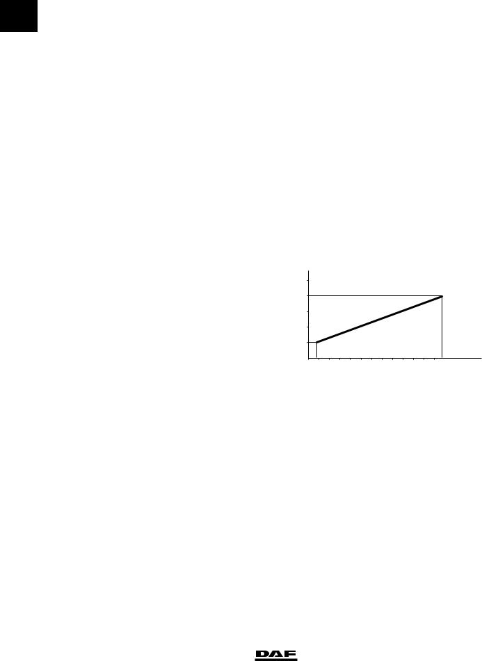
Pressure relief valve
overflow pressure |
10.0 bar |
1-4 |
© 200423 |
https://www.truck-manuals.net/
6 |
TECHNICAL DATA |
|
|
ΧΦ65/75/85 series |
Brake system and components |
Foot brake valve |
|
Type |
|
Make: Knorr DX 61A |
|
Pressure difference between |
|
circuits 1 and 2 |
0.25 bar |
Actuating pressure difference |
|
between circuits 1 and 2 |
0.2 bar |
| <![if ! IE]> <![endif]>[bar] |
11 |
|
|
|
|
|
|
|
|
|
P22 (P11=0) |
0 |
|
|
|
|
|
|
|
|
|
|
|
|
|
||
| <![if ! IE]> <![endif]>p21/22 |
10 |
|
|
|
|
|
|
|
|
|
|
|
|
9 |
|
|
|
|
|
|
|
|
|
|
|
|
|
8 |
|
|
|
|
|
|
|
|
|
|
|
|
|
|
|
|
|
|
|
|
|
|
|
|
|
|
|
|
7 |
|
|
|
|
21 |
|
|
|
|
|
|
|
|
6 |
|
|
|
|
|
|
|
|
|
|
||
|
|
|
|
|
|
|
|
|
|
22 |
|
|
|
|
5 |
|
|
|
|
|
|
|
|
|
|
|
|
| <![if ! IE]> <![endif]>Inshot 0.2–0.1 |
|
|
|
|
|
|
|
|
|
|
|
|
|
4 |
|
|
|
|
|
|
|
|
|
|
<![if ! IE]> <![endif]>Stroke (mm) |
|
|
3 |
|
|
|
|
|
|
|
|
|
|
|
||
2 |
|
|
|
|
|
|
|
|
|
|
|
||
1 |
|
|
|
|
|
|
|
|
|
|
|
||
0 |
1 |
2 |
3 |
4 |
5 |
6 |
7 |
8 |
9 |
10 11 12 13 14 |
|
||
|
|
|
|||||||||||
|
20 |
|
|
|
|
|
|
|
|
|
|
|
|
|
60 |
|
|
|
|
|
|
|
|
|
|
|
|
|
100 |
|
|
|
|
|
|
|
|
|
|
|
|
|
140 |
|
|
|
|
|
|
|
|
|
|
|
|
|
180 |
|
|
|
|
|
|
|
|
|
|
|
|
|
220 |
|
|
|
|
|
|
|
|
|
|
|
|
|
260 |
|
|
|
|
|
|
|
|
|
|
|
|
N |
|
|
|
|
|
|
|
|
380–20N |
|
|
||
|
|
|
|
|
|
|
|
|
|
|
|
R600542 |
|
Connection 11 |
circuit 1 supply |
||||||||||||||
Connection 12 |
circuit 2 supply |
||||||||||||||
Connection 21 |
circuit 1 braking pressure |
||||||||||||||
Connection 22 |
circuit 2 braking pressure |
||||||||||||||
Load sensing valve, leaf suspension |
|
|
|
|
|
|
|
|
|
|
|
|
|
|
|
Characteristic |
|
|
|
|
|
|
|
|
|
|
|
|
|
|
|
|
|
|
|
|
|
|
|
|
|
|
|
|
|
|
|
|
|
|
|
|
|
|
|
|
|
|
|
|
|
|
|
|
|
|
|
|
|
|
|
|
|
|
|
|
|
|
|
|
|
|
|
|
|
|
|
|
|
|
|
|
|
|
|
|
|
|
|
|
|
|
|
|
|
|
|
|
|
|
|
|
|
|
|
|
|
|
|
|
|
|
|
|
|
|
|
|
|
|
|
|
|
|
|
|
|
|
|
|
|
|
|
|
|
|
|
|
|
|
|
|
|
|
|
|
|
|
|
|
|
|
|
|
|
|
|
|
|
|
|
|
|
|
|
|
|
|
|
|
|
|
|
|
|
|
|
|
|
|
|
|
|
|
|
|
|
|
|
|
|
|
|
|
|
|
|
|
|
|
|
|
|
|
|
|
|
|
|
|
|
|
|
|
|
|
|
|
|
|
|
|
|
|
|
|
|
|
|
|
|
|
|
|
|
|
|
|
|
|
|
|
|
|
|
R600704
© 200423 |
1-5 |
https://www.truck-manuals.net/
TECHNICAL DATA
Brake system and components
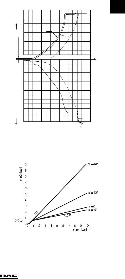
Load sensing valve, air suspension
0 |
Characteristic |
10 |
|
|
|||
|
<![if ! IE]> <![endif]>[bar] |
||
|
9 |
||
|
<![if ! IE]> <![endif]>p2 |
8 |
|
|
|
|
|
|
|
|
7 |
|
|
|
|
6
5
4
3
2
1
0.6–0.2
0
6
ΧΦ65/75/85 series
p41p42= 4.65 bar
p41p42= 3 bar
p41p42= 0.3 bar
1:1
1 |
2 |
3 |
4 |
5 |
6 |
7 |
8 |
9 |
10 |
|
|
|
|
|
|
|
|
|
|
p4 [bar] |
|
|
|
|
|
|
|
|
|
|
||
R600705
Brake light switch |
|
Type |
|
Make: Messmer 131 733 |
|
Cut-in pressure, brake light switch (make contact) |
0.4 - 0.6 bar |
Note: |
|
If the vehicle has EBS, the brake light switch is |
|
located in the foot brake valve. |
|
Low pressure switch |
|
Brake drum design |
|
Make: Wabco 441 014 ... |
|
Cut-out pressure (break contact) |
4.7 - 5.7 bar |
Disc brake design |
|
Make: Wabco 441 014 ... |
|
Cut-out pressure (break contact) |
6.1 - 7.1 bar |
1-6 |
© 200423 |
https://www.truck-manuals.net/
6
ΧΦ65/75/85 series
Empty/load relay valve |
|
Type |
|
Make: Wabco 973 011 106 |
|
Maximum reduction ratio |
1 : 1.5 |
Actuating pressure |
0.25 bar |
Fitted with internal filter and silencer |
|
Application: |
FAT vehicle |
Type |
|
Make: Wabco 973 011 107 |
|
Maximum reduction ratio |
1 : 2.7 |
Actuating pressure |
0.25 bar |
Fitted with internal filter and silencer |
|
Application: |
FAD vehicle |
|
FAC vehicle |
|
FAX vehicle |
|
FAL vehicle |
TECHNICAL DATA
Brake system and components
| <![if ! IE]> <![endif]>P2(bar) |
10 |
|
|
|
|
|
|
|
|
|
|
|
|
|
|
|
|
|
|
|
|
|
|
0 |
||
|
|
|
|
|
|
|
|
|
|
|
|
|
|
|
|
|
|
|
|
|
|
|||||
9 |
|
|
|
|
|
|
|
|
|
|
|
|
|
|
|
|
|
|
|
|
|
|
|
|||
|
|
|
|
|
|
|
|
|
|
|
|
|
|
|
|
|
|
|
|
|
|
|
||||
|
|
|
|
|
|
|
|
|
|
|
|
|
|
|
|
|
|
|
|
|
|
|
|
|||
|
8 |
|
|
|
|
|
|
|
|
|
|
|
|
|
|
|
|
|
|
|
|
|
|
|
||
|
|
|
|
|
|
|
|
|
|
|
|
|
|
|
|
|
|
|
|
|
|
|
|
|||
|
7 |
|
|
|
|
|
|
|
|
|
|
|
|
|
|
|
|
|
|
|
|
|
|
|
||
|
|
|
|
|
|
|
|
|
|
|
|
|
|
|
|
|
|
|
|
|
|
|
|
|||
|
6 |
|
|
|
|
|
|
|
|
|
|
|
|
|
|
|
|
|
|
|
|
|
|
|
||
|
|
|
|
|
|
|
|
|
|
|
|
|
|
|
|
|
|
|
|
|
|
|
|
|||
|
5 |
|
|
|
|
|
|
|
|
P42 = P41 |
|
|
|
|
|
|
|
|
|
|
|
|
|
|||
|
|
|
|
|
|
|
|
|
|
|
|
|
|
|
5 |
|
|
|
|
|
|
|
|
|||
|
|
|
|
|
|
|
|
|
|
|
|
|
|
|
|
|
|
|
|
|
|
|
|
|
|
|
|
|
|
|
|
|
|
|
|
|
|
|
|
|
|
|
|
|
. |
|
|
|
|
|
|
|
|
|
4 |
|
|
|
|
|
|
|
|
|
|
|
|
|
1:1 |
|
|
|
|
|
|
|
|
|||
|
|
|
|
|
|
|
|
|
|
|
|
|
|
|
|
|
|
|
|
|
|
|
|
|||
|
3 |
|
|
|
|
|
|
|
|
|
|
|
|
|
|
|
|
|
|
|
|
|
|
|
||
|
|
|
|
|
|
|
|
|
|
|
|
|
|
|
|
|
|
|
|
|
|
|
|
|||
|
2 |
|
|
|
|
|
|
|
|
|
|
|
|
|
|
|
|
|
|
|
|
|
|
|
||
|
1 |
|
|
|
|
|
|
|
|
P42 = 0 |
|
|
|
|
|
|
|
|
|
|
|
|
|
|||
|
|
|
|
|
|
|
|
|
|
|
|
|
|
|
|
|
|
|
|
|
|
|
|
|||
|
|
|
|
|
|
|
|
|
|
|
|
|
|
|
|
|
|
|
|
|
|
|
|
|||
|
|
|
|
|
|
|
|
|
|
|
|
|
|
|
|
|
|
|
|
|
|
|
|
|
|
|
|
0 |
|
1 |
2 |
3 |
4 |
5 |
6 |
7 |
8 |
9 |
10 |
|
|||||||||||||
|
|
|
|
|
0,25 |
+ 0,1 |
|
|
|
|
|
|
|
|
|
|
|
|
P41(bar) |
|
|
|
||||
|
|
|
|
|
|
|
|
|
|
|
|
|
|
|
|
|
|
|
|
|
|
|
|
|||
|
|
|
|
|
|
|
|
|
|
|
|
|
|
|
|
|
|
|
|
|
|
R600328 |
||||
| <![if ! IE]> <![endif]>P2(bar) |
10 |
|
|
|
|
|
|
|
|
|
|
|
|
|
|
|
|
|
|
|
|
|
|
|
||
|
|
|
|
|
|
|
|
|
|
|
|
|
|
|
|
|
|
|
|
|
|
|
||||
9 |
|
|
|
|
|
|
|
|
|
|
|
|
|
|
|
|
|
|
|
|
|
|
|
|||
|
|
|
|
|
|
|
|
|
|
|
|
|
|
|
|
|
|
|
|
|
|
|
|
|||
|
8 |
|
|
|
|
|
|
|
|
|
|
|
|
|
|
|
|
|
|
|
|
|
|
|
||
|
|
|
|
|
|
|
|
|
|
|
|
|
|
|
|
|
|
|
|
|
|
|
|
|||
|
7 |
|
|
|
|
|
|
|
|
|
|
|
|
|
|
|
|
|
|
|
|
|
|
|
||
|
|
|
|
|
|
|
|
|
|
|
|
|
|
|
|
|
|
|
|
|
|
|
|
|||
|
6 |
|
|
|
|
|
|
|
|
|
|
|
|
|
|
|
|
|
|
|
|
|
|
|
||
|
|
|
|
|
|
|
|
|
|
|
|
|
|
|
|
|
|
|
|
|
|
|
|
|||
|
5 |
|
|
|
|
|
|
|
|
P42 = P41 |
|
|
|
|
|
|
|
|
|
|
|
|
|
|||
|
|
|
|
|
|
|
|
|
|
|
|
|
|
|
|
|
|
|
|
|
|
|
|
|||
|
4 |
|
|
|
|
|
|
|
|
|
|
|
|
|
|
|
|
|
|
|
|
|
|
|
||
|
|
|
|
|
|
|
|
|
|
|
|
|
|
|
|
|
|
|
|
|
|
|
|
|||
|
3 |
|
|
|
|
|
|
|
|
|
|
|
|
|
|
|
|
|
|
|
|
|
|
|
||
|
|
|
|
|
|
|
|
|
|
|
|
|
|
|
.7 |
|
|
|
|
|
|
|
|
|||
|
|
|
|
|
|
|
|
|
|
|
|
|
|
|
|
|
|
|
|
|
|
|
|
|
|
|
|
2 |
|
|
|
|
|
|
|
|
|
|
|
|
|
1:2 |
|
|
|
|
|
|
|
|
|||
|
|
|
|
|
|
|
|
|
P42 |
= 0 |
|
|
|
|
|
|
|
|
|
|
|
|
|
|||
|
1 |
|
|
|
|
|
|
|
|
|
|
|
|
|
|
|
|
|
|
|
|
|
||||
|
|
|
|
|
|
|
|
|
|
|
|
|
|
|
|
|
|
|
|
|
|
|
|
|||
|
|
|
|
|
|
|
|
|
|
|
|
|
|
|
|
|
|
|
|
|
|
|
|
|||
|
|
|
|
|
|
|
|
|
|
|
|
|
|
|
|
|
|
|
|
|
|
|
|
|
|
|
|
0 |
|
1 |
2 |
3 |
4 |
5 |
6 |
7 |
8 |
9 |
10 |
|
|||||||||||||
|
|
|
|
|
0,25+ 0,1 |
|
|
|
|
|
|
|
|
|
|
|
|
P41(bar) |
|
|
|
|||||
|
|
|
|
|
|
|
|
|
|
|
|
|
|
|
|
|
|
|
|
|
|
|
|
|||
|
|
|
|
|
|
|
|
|
|
|
|
|
|
|
|
|
|
|
|
|
|
R600330 |
||||
© 200423 |
1-7 |
https://www.truck-manuals.net/
TECHNICAL DATA
Brake system and components
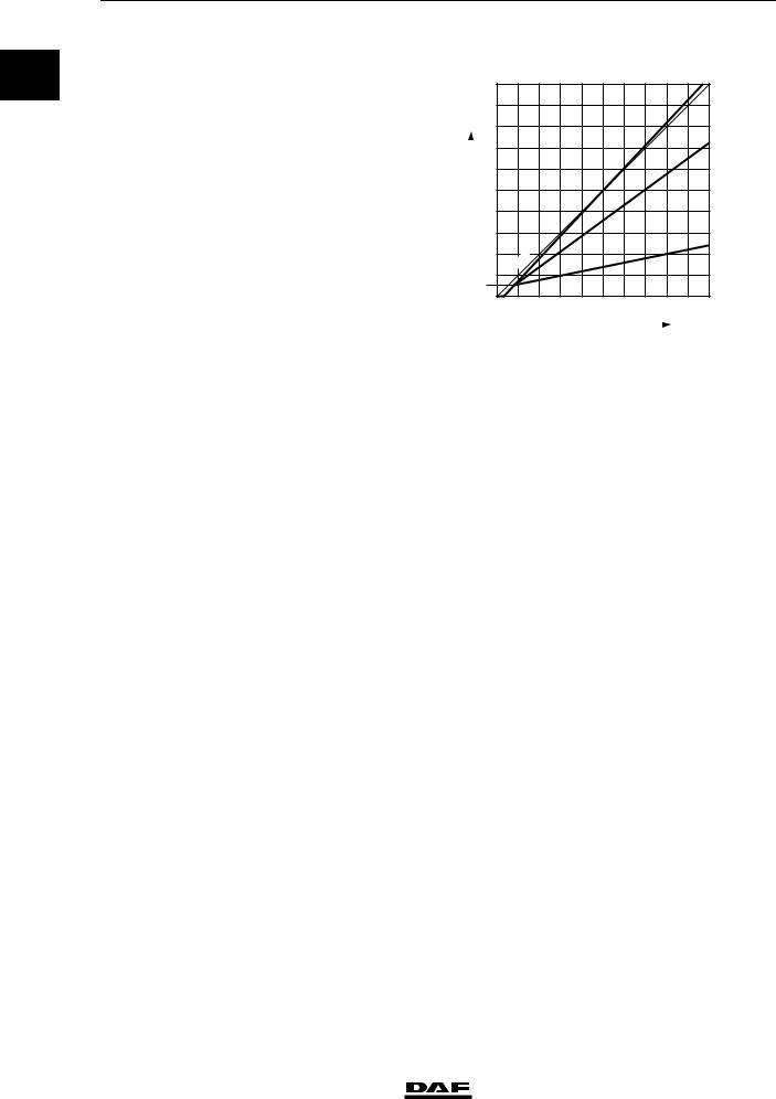
Relay valve
0 Version for parking brake
Make: Knorr AC 577A Fitted with silencer
Relay valve
Version for service brake
Make: Wabco 973 011 009
Fitted with internal filter and silencer
6
ΧΦ65/75/85 series
| <![if ! IE]> <![endif]>(bar) |
9 |
|
|
|
|
|
|
|
|
|
8 |
|
|
|
|
|
|
|
|
|
|
| <![if ! IE]> <![endif]>P2 |
|
|
|
|
|
|
|
|
|
|
7 |
|
|
|
|
|
|
|
|
|
|
|
|
|
|
|
|
|
|
|
|
|
|
6 |
|
|
|
|
|
|
|
|
|
|
5 |
|
|
|
|
|
|
|
|
|
|
4 |
|
|
|
|
|
|
|
|
|
|
3 |
|
|
|
|
|
|
|
|
|
|
2 |
|
|
|
|
|
|
|
|
|
|
1 |
|
|
|
|
|
|
|
|
|
|
0 |
1 |
2 |
3 |
4 |
5 |
6 |
7 |
8 |
9 |
|
|
|
|
|
|
|
|
|
P4 (bar) |
|
R 600363
10
9
0
8,9 -0,2
| <![if ! IE]> <![endif]>(bar)P2 |
8 |
|
|
|
|
|
|
|
|
|
|
6 |
|
|
|
|
|
|
|
|
|
|
|
|
7 |
|
|
|
|
|
|
|
|
|
|
|
5 |
|
|
|
|
|
|
|
|
|
|
|
4 |
|
|
|
|
|
|
|
|
|
|
|
3 |
|
|
|
|
|
|
|
|
|
|
|
2 |
|
|
|
|
|
|
|
|
|
|
|
1 |
|
|
|
|
|
|
|
|
|
|
|
0 |
1 |
2 |
3 |
4 |
5 |
6 |
7 |
8 |
9 |
10 |
|
|
|
0,5–0,1 |
|
|
|
|
|
|
P4 (bar) |
|
|
|
|
|
|
|
|
|
|
|
R 600602 |
|
1-8 |
© 200423 |
https://www.truck-manuals.net/
6 |
|
|
|
|
TECHNICAL DATA |
|||||||||||
|
|
|
|
|
|
|
|
|||||||||
ΧΦ65/75/85 series |
|
|
Brake system and components |
|||||||||||||
Relay valve |
|
|
|
|
|
|
|
|
|
|
|
|
|
|
|
|
10 |
|
|
|
|
|
|
|
|
|
|
|
|
|
|
0 |
|
Version for service brake |
|
|
|
|
|
|
|
|
|
|
|
|
|
|||
|
|
|
|
|
|
|
|
|
|
|
|
|
|
|
|
|
Make: Wabco 973 011 008 |
9,2-00,2 9 |
|
|
|
|
|
|
|
|
|
|
|
|
|
|
|
|
|
|
|
|
|
|
|
|
|
|
|
|
|
|
||
Fitted with internal filter and silencer |
|
|
|
|
|
|
|
|
|
|
|
|
|
|
|
|
|
8 |
|
|
|
|
|
|
|
|
|
|
|
|
|
|
|
|
|
|
|
|
|
|
|
|
|
|
|
|
|
|
|
|
|
7 |
|
|
|
|
|
|
|
|
|
|
|
|
|
|
|
|
6 |
|
|
|
|
|
|
|
|
|
|
|
|
|
|
|
|
|
|
|
|
|
|
|
|
|
|
|
|
|
|
|
|
|
5 |
|
|
|
|
|
|
|
|
|
|
|
|
|
|
|
|
4 |
|
|
|
|
|
|
|
|
|
|
|
|
|
|
|
|
|
|
|
|
|
|
|
|
|
|
|
|
|
|
|
|
|
3 |
|
|
|
|
|
|
|
|
|
|
|
|
|
|
|
|
2 |
|
|
|
|
|
|
|
|
|
|
|
|
|
|
|
|
1 |
|
|
|
|
|
|
|
|
|
|
|
|
|
|
|
|
|
|
|
|
|
|
|
|
|
|
|
|
|
|
|
|
|
0 |
|
|
|
|
|
|
|
|
|
|
|
|
|
|
|
|
|
1 |
2 |
3 |
4 |
5 |
6 |
7 |
8 |
9 |
10 |
|
||||
|
MAX. 0,2 |
|
|
|
|
|
|
|
|
|
|
|
|
|
|
|
|
|
|
|
|
|
|
|
|
|
|
R600640 |
|||||
ABS valve |
|
|
|
|
|
|
|
|
|
|
|
|
|
|
|
|
Resistance of magnet coil (at approx. 25 C) |
10 - 20 ohm |
|
|
|
|
|
|
|
|
|
|
|
|
|
||
Electrical connections
1.magnet coil bleed point
2.mass
3. |
magnet coil air admission point |
1 |
|
|
2 3
2 |
1 |
3
1 2 3
R600370
© 200423 |
1-9 |
https://www.truck-manuals.net/
|
TECHNICAL DATA |
6 |
|
|
|
|
Brake system and components |
ΧΦ65/75/85 series |
0 |
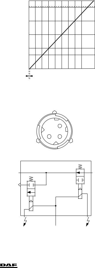
ASR solenoid valve |
|
1. Supply |
|
2.Port, two-way valve
3.Bleed
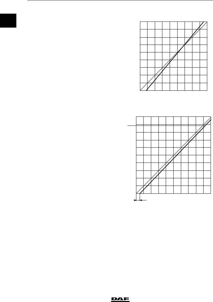
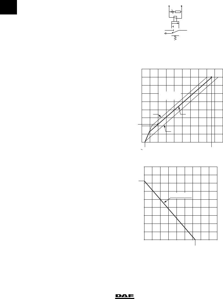
Trailer control valve
Type
Make: Knorr AC 599A
Explanation of graph
BCurve of intact circuit 1, circuit 2, or failure in circuit 1 or circuit 2
CSetting range, braking pressure advance
Advance |
|
Input pressure |
3 bar |
Output pressure |
3 bar |
(corresponds to 0.6 bar |
|
advance = factory setting) |
|
Advance adjustment |
|
Adjusting screw (Allen type, 6 mm) Clockwise increases the advance Anti-clockwise decreases the advance
Explanation of graph
Output pressure on connection 22 (P22). Graph is applicable if the parking brake is applied.
1-10
|
|
|
|
1 |
|
|
2 |
|
|
|
|
|
|
|
|
3 |
|
|
|
|
|
|
|
|
|
|
|
|
R600484 |
|
|
|
|
||
| <![if ! IE]> <![endif]>P22(bar) |
9 |
|
|
|
|
|
|
|
|
|
|
8 |
|
|
|
|
|
|
|
|
|
|
|
|
|
|
|
|
|
|
|
|
|
|
|
|
7 |
|
|
|
|
|
|
|
|
|
|
|
6 |
|
P11/12 = 8bar |
|
|
|
|
|
|
||
|
|
|
|
P43 = 8bar |
|
|
|
|
|
|
|
|
5 |
|
|
|
|
|
|
|
|
|
|
|
4 |
C |
|
|
|
B |
|
|
|
|
|
|
|
|
|
|
|
|
|
|
|
||
|
3 |
|
|
|
|
|
|
|
|
|
|
2,2 + 00,2 |
2 |
|
|
C |
|
|
|
|
|
|
|
|
|
|
|
|
|
|
|
|
|
||
|
1 |
|
|
|
|
|
|
|
|
|
|
|
0 |
1 |
2 |
3 |
4 |
5 |
6 |
7 |
8 |
9 |
10 |
|
<0,35 |
|
|
|
|
|
|
|
8,6 |
|
|
|
|
|
|
|
|
|
|
|
P41/42(bar) |
||
| <![if ! IE]> <![endif]>P22(bar) |
|
|
|
|
|
|
|
|
|
R600333 |
|
9 |
|
|
|
|
|
|
|
|
|
|
|
8 |
|
|
|
|
|
|
|
|
|
|
|
|
|
|
|
|
|
|
|
|
|
|
|
7,3 |
7 |
|
|
|
|
|
|
|
|
|
|
|
|
|
|
|
|
|
|
|
|
|
|
|
6 |
|
|
|
|
|
|
|
|
|
|
|
|
|
|
|
P11/12 = 8bar |
|
|
|
|
||
|
5 |
|
|
|
|
|
|
|
|
|
|
|
4 |
|
|
|
|
|
|
|
|
|
|
|
3 |
|
|
|
|
|
|
|
|
|
|
|
2 |
|
|
|
|
|
|
|
|
|
|
|
1 |
|
|
|
|
|
|
|
|
|
|
|
0 |
1 |
2 |
3 |
4 |
5 |
|
6 |
7 |
8 |
9 |
|
|
|
|
|
|
|
|
6,3 |
P43(bar) |
||
|
|
|
|
|
|
|
|
|
|||
|
|
|
|
|
|
|
|
|
R600332 |
|
|
|
|
|
|
|
|
|
|
|
© 200423 |
||
https://www.truck-manuals.net/
6 |
TECHNICAL DATA |
||
|
|
|
|
ΧΦ65/75/85 series |
Brake system and components |
||
Safety valve |
|
|
|
|
|
0 |
|
Type |
|
||
Make: Voss 0 268 874 200 |
|
|
|
Opening pressure reading |
approx. 16 bar |
||
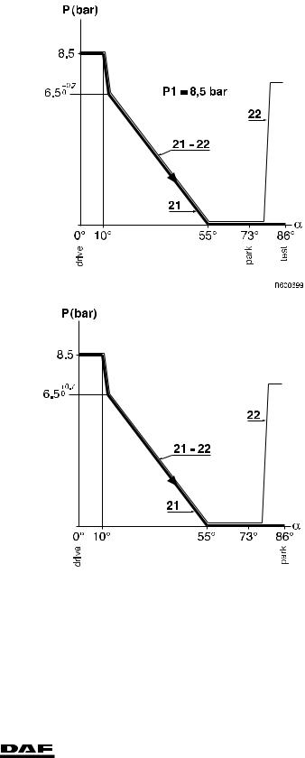
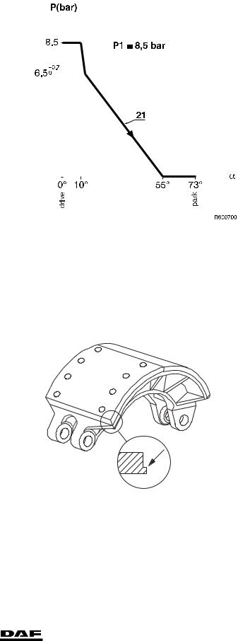
Parking brake valve with drawn vehicle |
|
|
|
connection |
|
|
|
Type |
|
|
|
Make: Knorr DPM90DA (with test position) |
|
|
|
Knorr DPM93D (without test position) |
|
|
|
Knorr DPM90AA (without test |
|
|
|
position with electrical switch) |
|
|
|
(special application) |
|
|
|
Max. output pressure |
|
in driving position |
|
(with test position) |
approx. 8.5 bar |
Max. output pressure |
|
in driving position |
|
(with test position) |
approx. 8.5 bar |
R600706
© 200423 |
1-11 |
https://www.truck-manuals.net/
|
|
TECHNICAL DATA |
|
|
6 |
|||
|
|
|
|
|
|
|
|
|
|
|
Brake system and components |
|
|
ΧΦ65/75/85 series |
|||
|
|
Parking brake without drawn vehicle |
|
|
|
|
||
0 |
|
|
|
|
|
|||
|
connection |
|
|
|
|
|
|
|
|
|
|
|
|
|
|
|
|
|
|
Type |
|
|
|
|
|
|
|
|
Make: |
Knorr DPM92D |
|
|
|
|
|
|
|
Max. output pressure |
|
|
|
|
|
|
|
|
in driving position |
approx. 8.5 bar |
|
|
|
|
|
|
|
|
|
|
|
|
|
|
|
|
|
|
|
|
|
|
|
|
|
|
|
|
|
|
|
|
Brake lining
Drum brakes
TYPE |
NOTES |
|
|
DAF 2100 |
Installed on LHD vehicles |
|
|
DAF 3100 |
Installed on RHD vehicles |
|
|
Beral 1561 |
09N044 leading rear axle (used on FTP vehicle) |
|
|
The bearing pattern of the brake lining can be improved by grinding down the brake lining to a diameter which is max. 1 mm smaller than the drum diameter.
The space between brake shoe and lining must not be more than 0.1 mm.
Minimum brake lining thickness
height of wear indicator or 1 mm above rivet head
M6002
1-12 |
© 200423 |
https://www.truck-manuals.net/

6 |
|
TECHNICAL DATA |
||
|
|
|
|
|
ΧΦ65/75/85 series |
|
Brake system and components |
||
09N044 leading rear axle (used on FTP |
|
|
|
|
|
|
0 |
||
vehicle) |
|
5 mm |
||
Minimum lining thickness |
|
|||
Disc brakes, SB7000 and SN7000 series |
|
|
|
|
|
|
|
|
|
TYPE |
NOTES |
|
|
|
|
|
|
|
|
DAF 1200 |
Fitted to all vehicles |
|
|
|
|
|
|
|
|
Brake drum General
A brake drum may be used until the inside diameter has reached the maximum permissible value, as specified in the table below.
As soon as this diameter is exceeded, the brake drum must be replaced.
Brake diameter |
Standard brake-drum |
Maximum in mm |
Maximum |
|
|
diameter in mm |
|
reconditioning |
|
|
|
|
|
dimension in mm |
|
|
|
|
|
12 3/8" |
|
Ovality |
|
|
314 |
+ 0,127 |
317,3 |
316,3 |
|
13" |
330,2 |
+ 0,127 |
333,2 |
332,3 |
|
|
|
|
|
15 1/2" |
393,7 |
+ 0,127 |
396,7 |
395,7 |
16" |
406,6 |
+ 0,250 |
409,6 |
408,6 |
|
|
|
|
|
16 1/2" |
420 |
+ 0,250 |
425 |
423 |
310 mm |
310 |
+ 0,210 |
313 |
312 |
|
|
|
|
|
325 mm |
325 |
+ 0,230 |
328 |
327 |
|
|
|
|
|
360 mm |
360 |
+ 0,230 |
363 |
362 |
|
|
|
|
|
375 mm |
375 |
+ 0,230 |
378 |
377 |
|
|
|
|
|
420 mm |
420 |
+ 0,250 |
425 |
423 |
|
|
|
|
|
09N044 leading rear axle (used on FTP |
|
|
||
vehicle) |
|
|
|
|
|
|
|
|
|
Brake diameter |
Standard brake-drum |
Maximum in mm |
Maximum |
|
|
diameter in mm |
|
reconditioning |
|
|
|
|
|
dimension in mm |
|
|
|
|
|
300 mm |
|
300 |
|
298 - 299 mm |
|
|
|
|
|
The ovality (deformation) of the brake drum is checked with the drum in position on the hub, or on a brake dynamometer.
Brake drums with cracks exceeding a width of 0.7 mm or a length of 50 mm may not be reused.
© 200423 |
1-13 |
https://www.truck-manuals.net/
|
|
TECHNICAL DATA |
6 |
|
|
|
|
|
|
Brake system and components |
ΧΦ65/75/85 series |
|
|
Automatic slack adjuster for drum brakes |
|
0 |
|
|
|
|
Automatic slack adjuster travel (Haldex) |
35 - 40 mm |
|
|
|
Reverse torque value of adjusting bolt |
> 18 Nm |
|
|
Axial play on the brake camshaft |
0.5 - 1.0 mm |
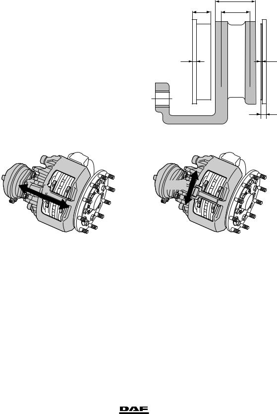
Brake pad
maximum brake pad |
|
thickness (C) |
30 mm |
0 minimum lining thickness (E) |
2 mm |
minimum brake pad thickness (F), |
|
with 9 mm rear plate thickness (D) |
11 mm |
replacing:
all brake pads at the same time for each axle, and with the specified lining only.
A
C B
D |
E |
Brake pad/brake disc play |
0.6 - 1.0 mm |
F
R600489
Brake caliper
A |
Y - X |
|
R600708 R600712
Brake caliper play in axial direction (direction A) |
0.6 - 1.0 mm |
Brake caliper play on the guide sleeves ("Y" - "X") |
Maximum 2.0 mm |
1-14 |
© 200423 |
https://www.truck-manuals.net/
6
ΧΦ65/75/85 series
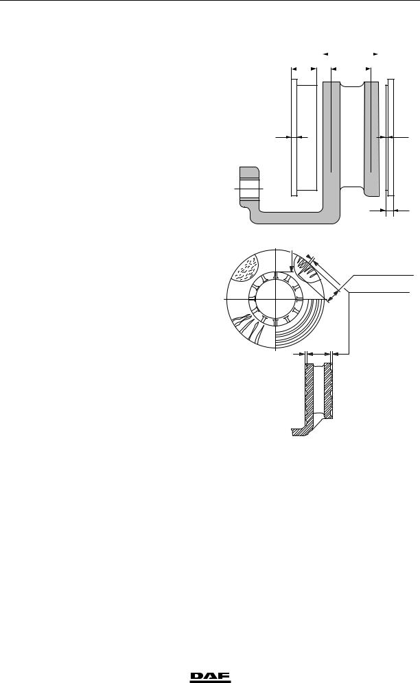
Brake disc |
|
maximum brake disc |
|
thickness (A) 0 |
45 mm |
minimum brake disc thickness (B) |
|
(rejection dimension, disc needs |
|
to be replaced) |
37 mm |
minimum thickness, turning |
|
dimension |
40 mm |
Note:
If it is established during brake pad replacement that the brake thickness is less than or equal to 39 mm, the brake disc must also be replaced.
The following signs of wear are permissible: |
A1 |
A1 crazy cracking.
B1 cracks running to the centre up to 1.5 mm wide and deep, max. 0.75 x friction surface width (a).
C1 unevenness in the disc surface up to
1.5 mm.
D1
Not permissible:
D1 through-going cracks.
© 200423
TECHNICAL DATA
Brake system and components
C |
|
|
A |
|
|
0 |
||
|
B |
|
|
|||||
|
||||||||
|
|
|
|
|
|
|
|
|
D |
E |
F
R600489

 B1 a
B1 a
max. 0,75 x a
max. 1,5 mm
C1
R600471
1-15
https://www.truck-manuals.net/
|
|
TECHNICAL DATA |
6 |
|
|
|
|
|
|
|
|
Brake system and components |
ΧΦ65/75/85 series |
|
|
|
1.2 TIGHTENING TORQUES |
|
|
0 |
|
|
||
|
|
|
|
|
|
|
Note: |
|
|
|
|
|
||
|
|
The tightening torques stated in this section are |
|
|
|
|
different from the standard tightening torques |
|
|
|
|
stated in the overview of the standard tightening |
|
|
|
|
torques. |
|
|
|
|
The other threaded connections not specified |
|
|
|
|
must therefore be tightened to the torque stated |
|
|
|
|
in the overview of standard tightening torques. |
|
|
|
|
When attachment bolts and nuts are replaced, |
|
|
|
|
it is important that - unless stated otherwise - |
|
|
|
|
these bolts and nuts are of exactly the same |
|
|
|
|
length and property class as those removed. |
|
|
|
|
SAFETY VALVE |
|
|
|
|
Attachment |
72 Nm |
|
|
|
BRAKE CALLIPER - BRAKE CARRIER |
|
|
|
Sliding sleeve Allen screws (SB7000) |
285 Nm (1) |
||
|
Sliding sleeve Allen screws (SN7000) |
180 Nm + 90 (1) |
||
|
Brake caliper attachment bolts |
440 Nm (2) |
||
|
Pressure tool, guide bush bellows |
8 Nm |
||
|
Rubber bearing bush pressure tool (only SN7000) |
8 - 45 Nm |
||
(1) |
Always use new bolts, provided with locking compound. |
|
||
|
|
|
New bolts are supplied with locking compound already |
|
|
|
|
applied. |
|
(2) |
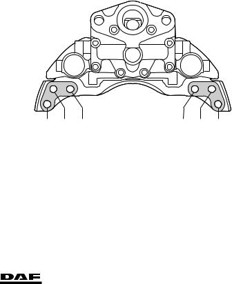
In the case of versions with Knorr disc brakes, |
|
||
|
|
|
the attachment of the brake caliper against the stub axle |
|
changed starting from production week 2002-25.
Five bolts are now used instead of six bolts. There is still a hole for the 6th bolt (5) on the brake carrier, but there is no hole on the stub axle.
|
6 |
3 |
2 |
1 |
4 |
5 |
|
|
|
|
|
|
R600520 |
BRAKE DISC |
|
|
|
|
|
|
Locking plate attachment bolts |
30 Nm |
|
|
|
|
|
1-16 |
© 200423 |
https://www.truck-manuals.net/
6 |
|
|
|
|
|
TECHNICAL DATA |
|||
|
|
|
|
|
|
|
|
|
|
ΧΦ65/75/85 series |
|
|
Brake system and components |
||||||
BRAKE CYLINDER |
|
|
|
|
|
|
|||
|
|
|
|
|
0 |
||||
Attachment nuts |
|
195 Nm |
|
|
|||||
Release bolt |
|
45 Nm |
|
|
|
|
|||
Release bolt (version with indication pin) |
|
75 Nm |
|
|
|
|
|||
SPRING BRAKE CYLINDER |
|
|
|
|
|
|
|||
Fixing nuts of spring brake cylinder |
|
180 - 210 Nm |
|||||||
Fixing bolts of the brake chamber clamping strap |
|
34 Nm |
|
|
|
|
|||
Release bolt (at least 5.1 bar) |
|
25 Nm |
|
|
|
|
|||
VOSS COUPLING 232 |
|
|
|
|
|
|
|||
Socket |
|
12 Nm |
|
|
|
|
|||
BLOW-OFF VALVE |
|
|
|
|
|
|
|||
Attachment |
|
25 Nm |
|
|
|
|
|||
Air compressor |
|
|
|
|
|
|
|||
There are two types of compressors: one version |
|
|
|
|
|
|
|||
used in production until 2002-47 and one version |
|
|
|
|
|
|
|||
used in production from 2002-48. |
|
|
|
|
|
|
|||
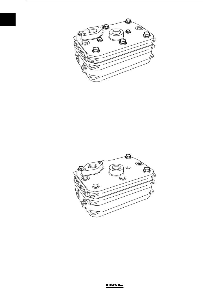
Compressors can be identified as follows: |
|
|
|
|
|
|
|||
1 |
|
|
1 |
|
2 |
|
|
||
|
|
|
|
|
|
|
|
|
|
|
|
|
|
|
|
|
|
|
|
|
|
|
|
|
|
|
|
|
|
|
|
|
|
|
|
|
|
|
|
R600743
< 2002-48 |
2002-48 |
The cylinder head of compressors used up to |
|
2002-48 consists of three aluminium parts (1). |
|
The cylinder head of compressors used from |
|
2002-48 consists of two aluminium parts (1) |
|
and a steel plate (2). |
|
Air compressor tightening torques greater |
|
than or equal to 2002-48 |
|
Delivery valve attachment nuts |
5 Nm + 90 angular displacement |
Connecting rod bolts |
6 Nm + 70 angular displacement |
© 200423 |
1-17 |
https://www.truck-manuals.net/
TECHNICAL DATA |
|
6 |
Brake system and components |
|
ΧΦ65/75/85 series |
0 |
5 |
|
1 |
|
|
|
|
|
3 |
7 |
4 |
|
|
8 |
2 |
|
|
6 |
|
|
|
|
|
R600742 |
Cylinder head bolts |
|
|
|
|
Phase 1, bolts 7 - 8 |
(in sequence) |
6 |
Nm |
|
Phase 2, bolts 7 - 8 |
(in sequence) |
90 angular displacement |
||
Phase 3, bolts 1 |
- 2 |
- 6 - 5 - 4 - 3 (in sequence) |
30 Nm |
|
Phase 4, bolts 1 |
- 2 |
- 6 - 5 - 4 - 3 (in sequence) |
90 angular displacement |
|
Phase 5, bolts 7 |
- 8 |
(in sequence) |
10 Nm |
|
Phase 6, bolts 7 |
- 8 |
(in sequence) |
90 angular displacement |
|
Air compressor tightening torques greater |
|
|
||
than or equal to 2002-48 |
|
|
||
Delivery valve attachment nuts |
5 |
Nm + 90 angular displacement |
||
Connecting rod bolts |
6 |
Nm + 70 angular displacement |
||
1
3 
 8
8
 6
6
Cylinder head bolts
Phase 1, bolts 1 - 2 - 3 - 4 - 5 - 6 (in sequence) Phase 2, bolts 1 - 2 - 3 - 4 - 5 - 6 (in sequence) Phase 3, bolts 7 - 8 (in sequence)
Phase 4, bolts 7 - 8 (in sequence)
5
 7 4
7 4
 2
2
R600742
30 Nm
90 angular displacement
7 Nm
90 angular displacement
1-18 |
© 200423 |
https://www.truck-manuals.net/
6 |
TECHNICAL DATA |
|
|
ΧΦ65/75/85 series |
Brake system and components |
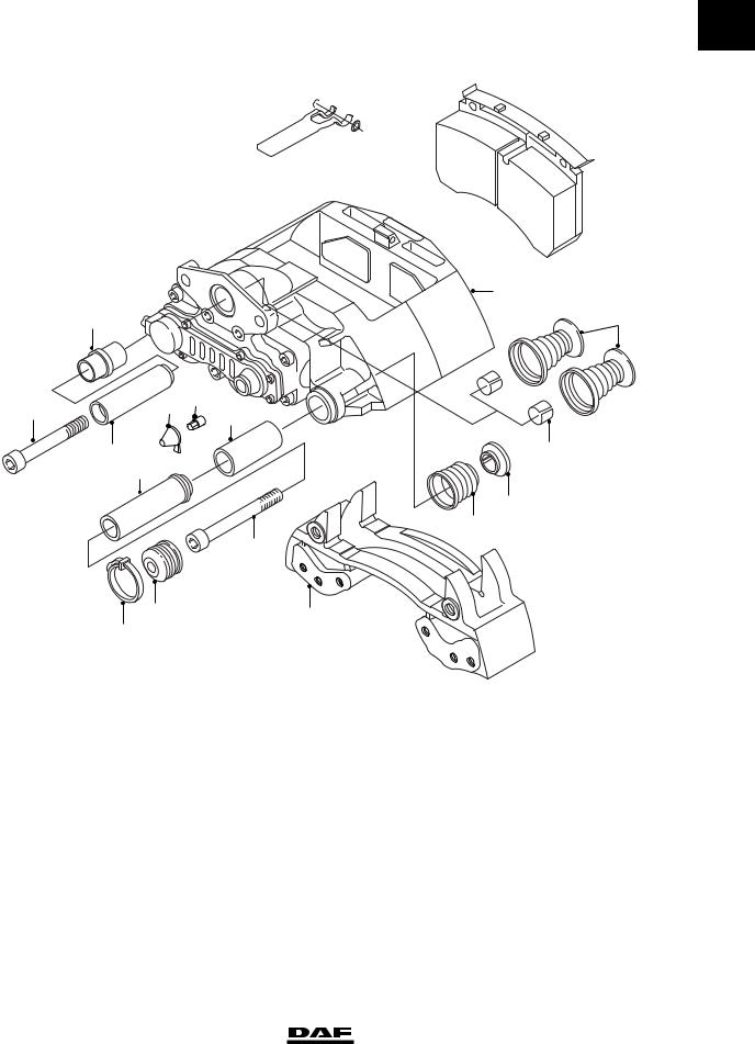
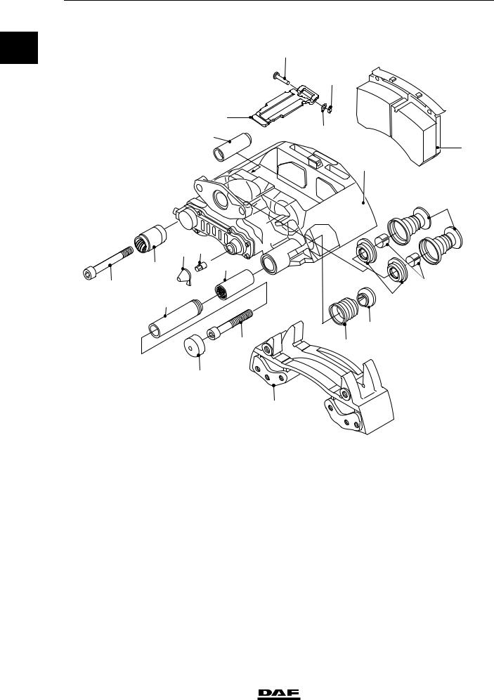
1.3 LUBRICANTS
0
Brake calliper Knorr SB7000

 20
20
18 


 21
21
19
 17
17
1
3 |
22 |
4 |
6 |
6a |
|
|
|
7 |
|
|
5 |
|
16 |
|
8 |
|
|
|
|
|
15 |
|
|
|
14 |
|
|
11 |
|
|
10 |
|
2 |
|
9 |
|
|
|
|
|
R600746 |
Renolit HLT2 (white) for parts 6, 7, 8, |
|
||
the adjusters (not shown), the brake cylinder |
|
||
lever and the flange surface for attachment of the |
|
||
brake cylinder |
|
|
(DAF no. 1448907) |
Sytheso GL EP1 (green), for parts 3, 5 |
(DAF no. 1448908) |
||
© 200423 |
1-19 |
https://www.truck-manuals.net/
TECHNICAL DATA |
|
6 |
Brake system and components |
ΧΦ65/75/85 series |
|
Knorr SN7000 |
|
|
0 |
|
20 |
|
|
21 |
|
18 |
|
|
5 |
19 |
|
17 |
|
|
|
|
|
|
1 |
|
|
22 |
6 |
6a |
|
3 |
7 |
|
4 |
|
16 |
8 |
|
23 |
|
|
15 |
|
11 |
14 |
|
10 |
|
|
|
2 |
|
|
R600755 |
Renolit HLT2 (white) for parts 3, 6, 7, 8, |
|
|
the adjusters (not shown), the brake cylinder |
|
|
lever and the flange surface for attachment |
|
|
of the brake cylinder |
|
(DAF no. 1448907) |
1-20 |
© 200423 |
https://www.truck-manuals.net/

6 |
|
TECHNICAL DATA |
|
|
|
|
|
|
|
ΧΦ65/75/85 series |
Braking performance and brake equalisation |
|
|
|
2. BRAKING PERFORMANCE AND BRAKE EQUALISATION |
|
|
||
|
0 |
|||
2.1 GENERAL |
|
|
|
|
|
|
|
|
|
EBS tyre class |
|
|
|
|
|
|
|
|
|
The tyre sizes are classified into tyre classes. |
|
|
|
|
This tyre class information is necessary |
|
|
|
|
to be able to assess the brake presentation, |
|
|
|
|
by measurements of brake force. |
|
|
|
|
This tyre class information is also necessary |
|
|
|
|
for the EBS system to be able to evaluate |
|
|
|
|
whether the electric EBS unit is programmed |
|
|
|
|
when the tyre size is changed.. |
|
|
|
|
Tyre size change in EBS system |
|
|
|
|
If the tyre size is changed in an EBS system and |
|
|
|
|
the tyre size of the front and rear axle no longer |
|
|
|
|
fall in the same tyre class, the changed tyre sizes |
|
|
|
|
must be programmed into the electronic EBS |
|
|
|
|
unit. |
|
|
|
|
|
|
|
|
|
Tyre class |
|
Tyre size |
|
|
|
|
|
|
|
Class 0 |
|
215/75 R 17.5 |
|
|
|
|
|
|
|
|
|
235/75 R 17.5 |
|
|
|
|
|
|
|
Class 1 |
|
295/60 R 22.5 |
|
|
|
|
|
|
|
|
|
255/70 R 22.5 |
|
|
|
|
|
|
|
|
|
315/60 R 22.5 |
|
|
|
|
|
|
|
|
|
275/70 R 22.5 |
|
|
|
|
|
|
|
Class 2 |
|
305/70 R 22.5 |
|
|
|
|
|
|
|
|
|
315/70 R 22.5 |
|
|
|
|
|
|
|
|
|
385/55 R 22.5 |
|
|
|
|
|
|
|
|
|
295/80 R 22.5 |
|
|
|
|
|
|
|
|
|
11 R 22.5 |
|
|
|
|
|
|
|
Class 3 |
|
385/65 R 22.5 |
|
|
|
|
|
|
|
|
|
315/80 R 22.5 |
|
|
|
|
|
|
|
|
|
11.00 R 20 |
|
|
|
|
|
|
|
|
|
12 R 22.5 |
|
|
|
|
|
|
|
|
|
12.00 R 20 |
|
|
|
|
|
|
|
|
|
13 R 22.5 |
|
|
|
|
|
|
|
© 200423 |
2-1 |
https://www.truck-manuals.net/
TECHNICAL DATA |
6 |
|
|
Braking performance and brake equalisation |
ΧΦ65/75/85 series |
Tyre size change in EBS 2 system
0 |
If the tyre size is changed in an EBS 2 system and |
|
|
|
the tyre size of the front and rear axle no longer |
|
fall in the same tyre class, it is not necessary to |
|
program the electronic ESB 2 unit because the |
|
electronic ESB 2 unit will automatically recognise |
|
this change in tyre size. |
|
OVERVIEW OF BRAKING FORCES OF |
|
EBS SYSTEM |
|
This overview lists the braking forces graphs |
|
based on tyre size. These braking force graphs |
|
apply to the prime mover with EBS; these braking |
|
force graphs can be used to check the braking |
|
performance of an EBS prime mover. |
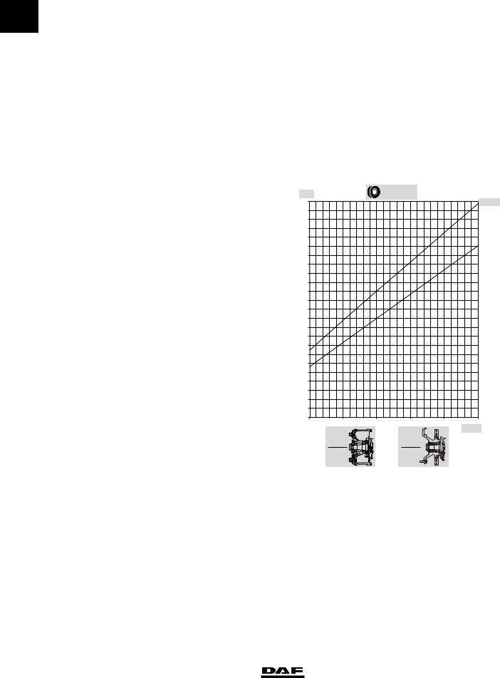
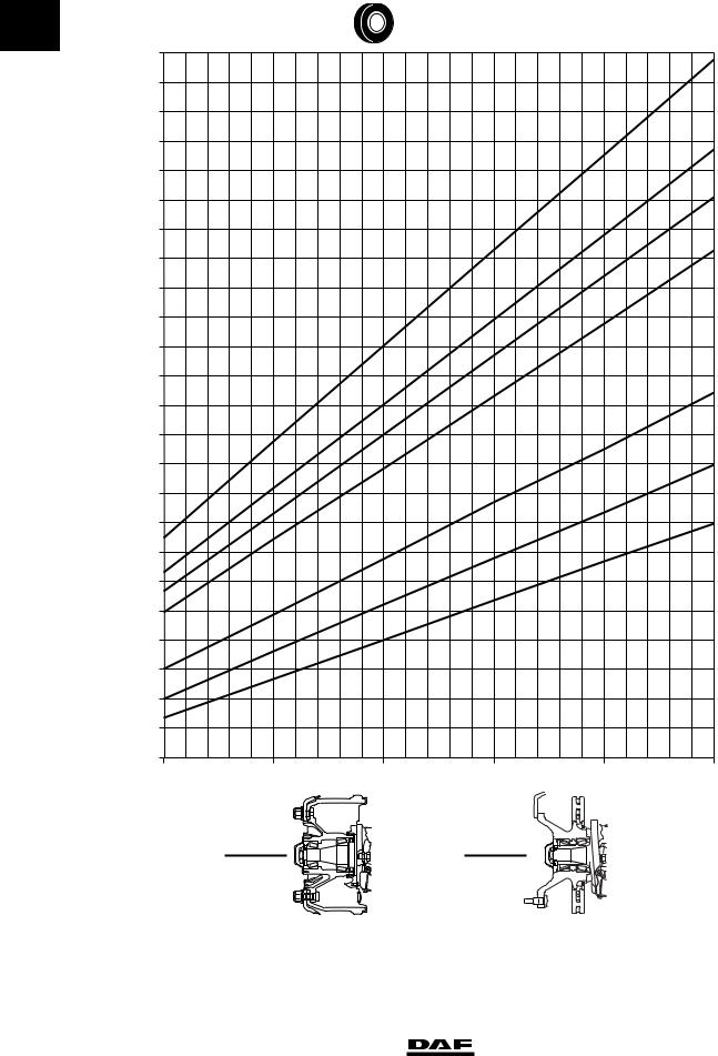
Graph explanation
1Brake force per wheel (N)
2Tyre size
3Type of brake cylinder + brake lever length (if applicable)
4Brake drum design
5Disc brake construction
6Pressure in brake cylinder (P)
7Reference line of measured braking force per wheel; the example shows a brake drum construction and a 27" brake cylinder with
a brake lever length of 165 mm.
8Reference line of the measured braking force per wheel; the example shows a disk brake construction and a 24" brake cylinder.
1 |
|
|
2 |
|
|
|
|
295/60R22,5 |
|
3 |
|
F (N) |
|
|
|
||
|
|
|
|
||
27000 |
|
|
|
|
27"-165 |
26000 |
|
|
|
|
|
25000 |
|
|
|
|
|
24000 |
|
|
|
|
|
23000 |
|
|
|
|
|
22000 |
|
|
7 |
|
24" |
|
|
|
|
||
21000 |
|
|
|
|
|
|
|
|
|
|
|
20000 |
|
|
|
8 |
|
19000 |
|
|
|
|
|
18000 |
|
|
|
|
|
17000 |
|
|
|
|
|
16000 |
|
|
|
|
|
15000 |
|
|
|
|
|
14000 |
|
|
|
|
|
13000 |
|
|
|
|
|
12000 |
|
|
|
|
|
11000 |
|
|
|
|
|
10000 |
|
|
|
|
|
9000 |
|
|
|
|
|
8000 |
|
|
|
|
|
7000 |
|
|
|
|
|
6000 |
|
|
|
|
|
5000 |
|
|
|
|
|
4000 |
|
|
|
|
|
3000 |
|
|
|
|
|
2 |
2,5 |
3 |
3,5 |
4 |
4,5 |
|
4 |
|
5 |
|
P (bar) |
|
|
|
6 |
||
|
|
|
|
|
|
|
|
|
|
|
R600879 |
2-2 |
© 200423 |
https://www.truck-manuals.net/

6 |
TECHNICAL DATA |
|
|
ΧΦ65/75/85 series |
Braking performance and brake equalisation |
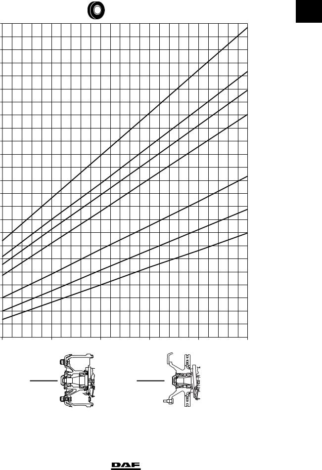
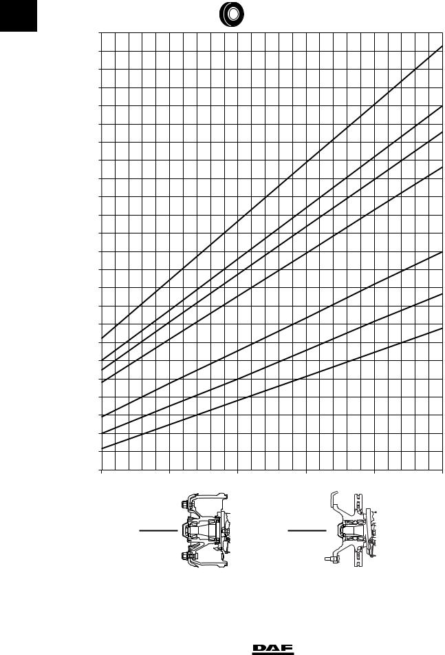
Braking force graphs
F (N) |
|
|
235/75R17,5 |
|
0 |
|
|
|
|
||
|
|
|
|
|
|
6000 |
|
|
|
|
|
5500 |
|
|
|
|
9"-125 |
|
|
|
|
|
|
5000 |
|
|
|
|
|
4500 |
|
|
|
|
|
4000 |
|
|
|
|
|
3500 |
|
|
|
|
|
3000 |
|
|
|
|
|
2500 |
|
|
|
|
|
2000 |
|
|
|
|
|
2 |
2,5 |
3 |
3,5 |
4 |
4,5 |
P (bar)
R600865
© 200423 |
2-3 |
https://www.truck-manuals.net/
TECHNICAL DATA |
6 |
|
|
Braking performance and brake equalisation |
ΧΦ65/75/85 series |
0 |
F (N) |
|
|
295/60R22,5 |
|
|
|
27000 |
|
|
|
|
27"-165 |
|
26000 |
|
|
|
|
|
|
25000 |
|
|
|
|
|
|
24000 |
|
|
|
|
24"-165 |
|
23000 |
|
|
|
|
|
|
22000 |
|
|
|
|
24" |
|
|
|
|
|
|
|
|
21000 |
|
|
|
|
|
|
20000 |
|
|
|
|
22" |
|
|
|
|
|
|
|
|
19000 |
|
|
|
|
|
|
18000 |
|
|
|
|
|
|
17000 |
|
|
|
|
|
|
16000 |
|
|
|
|
16" |
|
|
|
|
|
|
|
|
15000 |
|
|
|
|
|
|
14000 |
|
|
|
|
|
|
13000 |
|
|
|
|
14" |
|
12000 |
|
|
|
|
|
|
11000 |
|
|
|
|
12" |
|
10000 |
|
|
|
|
|
|
9000 |
|
|
|
|
|
|
8000 |
|
|
|
|
|
|
7000 |
|
|
|
|
|
|
6000 |
|
|
|
|
|
|
5000 |
|
|
|
|
|
|
4000 |
|
|
|
|
|
|
3000 |
|
|
|
|
|
|
2 |
2,5 |
3 |
3,5 |
4 |
4,5 |
P (bar)
R600866
2-4 |
© 200423 |
https://www.truck-manuals.net/
6 |
TECHNICAL DATA |
|
|
ΧΦ65/75/85 series |
Braking performance and brake equalisation |
F (N) |
|
|
255/70R22,5 |
|
0 |
27000 |
|
|
|
|
27"-165 |
26000 |
|
|
|
|
|
25000 |
|
|
|
|
|
24000 |
|
|
|
|
|
23000 |
|
|
|
|
24"-165 |
|
|
|
|
|
|
22000 |
|
|
|
|
24" |
21000 |
|
|
|
|
|
20000 |
|
|
|
|
22" |
19000 |
|
|
|
|
|
18000 |
|
|
|
|
|
17000 |
|
|
|
|
|
16000 |
|
|
|
|
|
15000 |
|
|
|
|
16" |
|
|
|
|
|
|
14000 |
|
|
|
|
|
13000 |
|
|
|
|
14" |
12000 |
|
|
|
|
|
11000 |
|
|
|
|
12" |
10000 |
|
|
|
|
|
9000 |
|
|
|
|
|
8000 |
|
|
|
|
|
7000 |
|
|
|
|
|
6000 |
|
|
|
|
|
5000 |
|
|
|
|
|
4000 |
|
|
|
|
|
3000 |
|
|
|
|
|
2 |
2,5 |
3 |
3,5 |
4 |
4,5 |
P (bar)
R600867
© 200423 |
2-5 |
https://www.truck-manuals.net/
TECHNICAL DATA |
6 |
|
|
Braking performance and brake equalisation |
ΧΦ65/75/85 series |
0 |
F (N) |
|
|
315/60R22,5 |
|
|
|
27000 |
|
|
|
|
|
|
26000 |
|
|
|
|
27"-165 |
|
|
|
|
|
|
|
|
25000 |
|
|
|
|
|
|
24000 |
|
|
|
|
|
|
23000 |
|
|
|
|
24"-165 |
|
22000 |
|
|
|
|
24" |
|
|
|
|
|
|
|
|
21000 |
|
|
|
|
|
|
20000 |
|
|
|
|
22" |
|
|
|
|
|
|
|
|
19000 |
|
|
|
|
|
|
18000 |
|
|
|
|
|
|
17000 |
|
|
|
|
|
|
16000 |
|
|
|
|
|
|
15000 |
|
|
|
|
16" |
|
14000 |
|
|
|
|
|
|
13000 |
|
|
|
|
14" |
|
12000 |
|
|
|
|
|
|
11000 |
|
|
|
|
12" |
|
10000 |
|
|
|
|
|
|
9000 |
|
|
|
|
|
|
8000 |
|
|
|
|
|
|
7000 |
|
|
|
|
|
|
6000 |
|
|
|
|
|
|
5000 |
|
|
|
|
|
|
4000 |
|
|
|
|
|
|
3000 |
|
|
|
|
|
|
2 |
2,5 |
3 |
3,5 |
4 |
4,5 |
P (bar)
R600868
2-6 |
© 200423 |
https://www.truck-manuals.net/
Loading...