


5 |
CONTENTS |
|
CF65/75/85 Series ≥0E621376 |
|
|
|
TECHNICAL DATA |
|
|
DIAGNOSTICS |
|
|
COMPONENTS |
|
|
WIRING REPAIR |
|
|
BATTERIES |
|
CONNECTION OF ACCESSORIES
READING DIAGRAMS
LOCATION OF COMPONENTS
LOCATION OF CONNECTORS
ELECTRICAL SYSTEM
CHANGES IN THE ELECTRICAL SYSTEM
ELECTRICAL SYSTEM: OPTIONS AND SPECIAL APPLICATIONS
0
1
2
3
4
5
6
7
8
9
10
11
12
200520 |
|
|
|
DW23271004 |
|
https://www.truck-manuals.net/ |
|||||
|
|
||||
https://www.truck-manuals.net/

5 |
TECHNICAL DATA |
|
CF65/75/85 series ≥0E621376 |
Contents |
|
CONTENTS
Page Date 0
1. COMPONENTS . . . . . . . . . . . . . . . . . . . . . . . . . . . . . . . . . . . . . . . . . . . . . . . . . . . . . . . . 1-1 . . . . 200404 1.1 General . . . . . . . . . . . . . . . . . . . . . . . . . . . . . . . . . . . . . . . . . . . . . . . . . . . . . . . . . 1-1 . . . . 200404 1.2 Tightening torques . . . . . . . . . . . . . . . . . . . . . . . . . . . . . . . . . . . . . . . . . . . . . . . . 1-3 . . . . 200404
200404 |
|
|
|
1 |
|
https://www.truck-manuals.net/ |
|||||
|
|
||||

TECHNICAL DATA |
5 |
Contents |
CF65/75/85 series ≥0E621376 |
0
2 |
|
|
200404 |
|
|
||
|
https://www.truck-manuals.net/ |
||

5 |
|
|
|
|
|
|
TECHNICAL DATA |
|||
CF65/75/85 series ≥0E621376 |
|
|
|
|
Components |
|
||||
1. COMPONENTS |
|
|
|
|
|
|
|
|
||
1.1 GENERAL |
|
|
|
|
|
|
|
0 |
||
|
|
|
|
|
|
|
|
|||
Bulbs |
|
|
|
|
|
|
|
|
|
|
|
|
|
|
|
|
|
|
|
|
|
Headlight (main beam) |
|
|
halogen |
70 W |
||||||
Headlight (dipped beam) |
|
|
halogen |
70 W |
||||||
Parking light |
|
|
|
|
spherical bulb |
5 W |
||||
Rear light |
|
|
|
|
spherical bulb |
2 x 5 W |
||||
Rear fog lamp |
|
|
|
|
spherical bulb |
21 W |
||||
Reversing light |
|
|
|
|
spherical bulb |
21 W |
||||
Stop light |
|
|
|
|
spherical bulb |
21 W |
||||
Direction indicator lamp |
|
|
spherical bulb |
21 W |
||||||
Marker light |
|
|
|
|
spherical bulb |
5 W |
||||
Side marker light |
|
|
special type |
3 W |
||||||
Combilamp: |
fog lamp |
|
|
halogen |
70 W |
|||||
|
spotlight |
|
|
halogen |
70 W |
|||||
Interior lighting |
|
|
|
|
spherical bulb |
10 and 21 W |
||||
Bunk light |
|
|
|
|
spherical bulb |
10 W |
||||
Stepwell lighting |
|
|
spherical bulb |
5 W |
||||||
Marker light |
|
|
|
|
spherical bulb |
5 W |
||||
Work lamp: |
white |
|
|
halogen lamp |
70 W |
|||||
|
yellow |
|
|
spherical bulb |
35 W |
|||||
|
|
|
|
|
|
|
|
|
|
|
|
|
|
Max. current and wire diameter (mm2) |
|
|
|
|
|||
Wire diameter |
|
< 2 m |
2 - 4 m |
|
4 - 8 m |
|
> 8 m |
|
|
|
|
|
|
|
|
|
|
|
|
|
|
1 |
|
|
9 |
5 |
|
4 |
|
|
|
|
|
|
|
|
|
|
|
|
|
|
|
1.5 |
|
|
22.5 |
13.5 |
|
7.5 |
|
6 |
|
|
|
|
|
|
|
|
|
|
|
|
|
2.5 |
|
|
37.5 |
22.5 |
|
12.5 |
|
10 |
|
|
|
|
|
|
|
|
|
|
|
|
|
4 |
|
|
60 |
36 |
|
20 |
|
16 |
|
|
|
|
|
|
|
|
|
|
|
|
|
6 |
|
|
90 |
54 |
|
30 |
|
24 |
|
|
|
|
|
|
|
|
|
|
|
|
|
10 |
|
|
150 |
90 |
|
50 |
|
40 |
|
|
|
|
|
|
|
|
|
|
|
|
|
16 |
|
|
240 |
144 |
|
80 |
|
64 |
|
|
|
|
|
|
|
|
|
|
|
|
|
25 |
|
|
375 |
225 |
|
125 |
|
100 |
|
|
|
|
|
|
|
|
|
|
|
|
|
35 |
|
|
525 |
315 |
|
175 |
|
140 |
|
|
|
|
|
|
|
|
|
|
|
|
|
50 |
|
|
750 |
450 |
|
250 |
|
200 |
|
|
|
|
|
|
|
|
|
|
|
|
|
70 |
|
|
1050 |
630 |
|
350 |
|
280 |
|
|
|
|
|
|
|
|
|
|
|
|
|
95 |
|
|
1425 |
855 |
|
475 |
|
380 |
|
|
|
|
|
|
|
|
|
|
|
|
|
120 |
|
|
1800 |
1080 |
|
600 |
|
480 |
|
|
|
|
|
|
|
|
|
|
|
|
|
200404 |
|
|
|
1-1 |
|
https://www.truck-manuals.net/ |
|||||
|
|
||||
|
TECHNICAL DATA |
|
|
|
5 |
|
Components |
|
CF65/75/85 series ≥0E621376 |
||
|
Alternator |
|
|
|
|
0 |
NCB1 |
|
|
|
|
Max. current |
|
80 A |
|
|
|
|
|
|
|
||
|
Rated voltage |
|
28 V |
|
|
|
NCB2 |
|
|
|
|
|
Max. current |
|
100 A |
|
|
|
Rated voltage |
|
28 V |
|
|
|
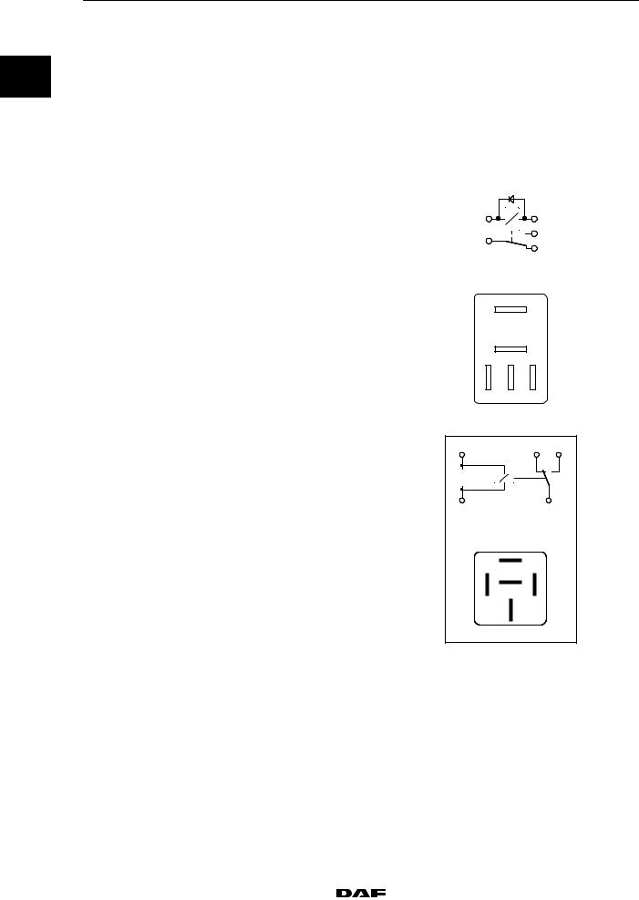
Micro relay |
|
|
|
|
|
Maximum cut in current |
|
|
|
|
|
making connection between |
10 A |
+1 |
|
2 |
|
points 3 and 5: |
|
|
5 |
|
|
Maximum cut out current |
|
|
|
|
|
|
+3 |
|
4 |
|
|
breaking connection between |
|
|
||
|
|
|
|
||
|
5 A |
|
|
|
|
|
points 3 and 4: |
|
|
E500146 |
|
|
|
|
|
|
3 |
|
|
|
|
5 |
|
|
|
|
2 |
4 |
1 |
|
|
|
|
|
E500147 |
|
Mini relay |
|
|
|
|
|
Maximum cut in current |
|
86 |
|
87a 87 |
|
making connection between |
|
|
||
|
|
|
|
|
|
|
points 30 and 87: |
20 A |
|
|
|
|
Maximum cut out current |
|
|
|
|
|
breaking connection between |
|
|
|
|
|
points 30 and 87a: |
10 A |
85 |
|
30 |
|
|
|
|
||
|
87 |
86 |
87a |
85 |
|
|
30 |
E500169
Handheld transmitter CDS |
|
Battery type (2x) |
CR1620, 3 V |
1-2 |
|
|
200404 |
|
|
||
|
https://www.truck-manuals.net/ |
||

5 |
|
TECHNICAL DATA |
||
CF65/75/85 series ≥0E621376 |
|
Components |
|
|
1.2 TIGHTENING TORQUES |
|
|
|
|
|
|
|
|
|
Tightening torques |
|
|
|
0 |
|
|
|
|
|
Drive pulley |
80 |
Nm 5 Nm |
|
|
|
||||
B+ connection |
15 |
Nm |
||
Chassis earth connection |
65 |
Nm |
||
200404 |
|
|
|
1-3 |
|
https://www.truck-manuals.net/ |
|||||
|
|
||||

TECHNICAL DATA |
5 |
Components |
CF65/75/85 series ≥0E621376 |
0
1-4 |
|
|
200404 |
|
|
||
|
https://www.truck-manuals.net/ |
||

5 |
|
|
DIAGNOSTICS |
|
||
CF65/75/85 Series ≥0E621376 |
|
Contents |
|
|
||
CONTENTS |
|
|
|
|
||
|
|
|
Page |
Date |
|
|
1. |
FAULT FINDING . . . . . . . . . . . . . . . . . . . . . . . . . . . . . . . . . . . . . . . . . . . . . . . . . . . . |
. . . 1-1 . . |
. . 200520 |
|
|
|
|
1.1 |
Short circuits . . . . . . . . . . . . . . . . . . . . . . . . . . . . . . . . . . . . . . . . . . . . . . . . . . . |
. . 1-2 . . |
. . 200520 |
|
|
|
|
1 |
||||
|
1.2 |
Open circuit . . . . . . . . . . . . . . . . . . . . . . . . . . . . . . . . . . . . . . . . . . . . . . . . . . . . |
. . 1-3 . . |
. . 200520 |
|
|
|
1.3 |
Earthing problems . . . . . . . . . . . . . . . . . . . . . . . . . . . . . . . . . . . . . . . . . . . . . . |
. . 1-4 . . |
. . 200520 |
|
|
2. |
BATTERIES |
2-1 |
200520 |
|
|
|
|
|
|||||
|
2.1 |
Fault-finding table . . . . . . . . . . . . . . . . . . . . . . . . . . . . . . . . . . . . . . . . . . . . . . . |
. . 2-1 . . |
. . 200520 |
|
|
|
2.2 |
Service life . . . . . . . . . . . . . . . . . . . . . . . . . . . . . . . . . . . . . . . . . . . . . . . . . . . . . |
. . 2-4 . . |
. . 200520 |
|
|
3. |
ALTERNATOR . . . . . . . . . . . . . . . . . . . . . . . . . . . . . . . . . . . . . . . . . . . . . . . . . . . . . . . |
. . 3-1 . . |
. . 200520 |
|
|
|
|
3.1 |
Fault-finding table . . . . . . . . . . . . . . . . . . . . . . . . . . . . . . . . . . . . . . . . . . . . . . . |
. . 3-1 . . |
. . 200520 |
|
|
4. |
XENON LIGHTING . . . . . . . . . . . . . . . . . . . . . . . . . . . . . . . . . . . . . . . . . . . . . . . . . . . |
. . 4-1 . . |
. . 200520 |
|
|
|
|
4.1 |
Fault-finding table . . . . . . . . . . . . . . . . . . . . . . . . . . . . . . . . . . . . . . . . . . . . . . . |
. . 4-1 . . |
. . 200520 |
|
|
200520 |
|
|
|
1 |
|
https://www.truck-manuals.net/ |
|||||
|
|
||||

DIAGNOSTICS |
5 |
Contents |
CF65/75/85 Series ≥0E621376 |
1
2 |
|
|
200520 |
|
https://www.truck-manuals.net/ |
||
5 |
DIAGNOSTICS |
||
CF65/75/85 Series ≥0E621376 |
Fault finding |
|
|
1. FAULT FINDING |
|
|
|
The following test equipment and tools can be |
|
|
|
used to trace faults. |
|
|
|
1. The best instrument for this is a digital |
|
|
|
multimeter. This instrument can be used to |
|
|
|
|
|
1 |
|
measure voltages, currents and resistances |
|
|
|
avoiding reading errors, and it can be used |
|
||
to trace virtually any faults. |
|
|
|
|
|
|
|
2. Many, but not all, faults are easily traced by |
|
|
|
means of warning lamps. Failures caused |
|
|
|
by poor earthing cannot normally be |
|
|
|
detected by a warning lamp or buzzer. |
|
|
|
The most frequently occurring faults are:
a.short circuit
b.open circuits
c.earthing problems (poor earthing due to corrosion).
200520 |
|
|
|
1-1 |
|
https://www.truck-manuals.net/ |
|||||
|
|
||||
DIAGNOSTICS |
5 |
Fault finding |
CF65/75/85 Series ≥0E621376 |
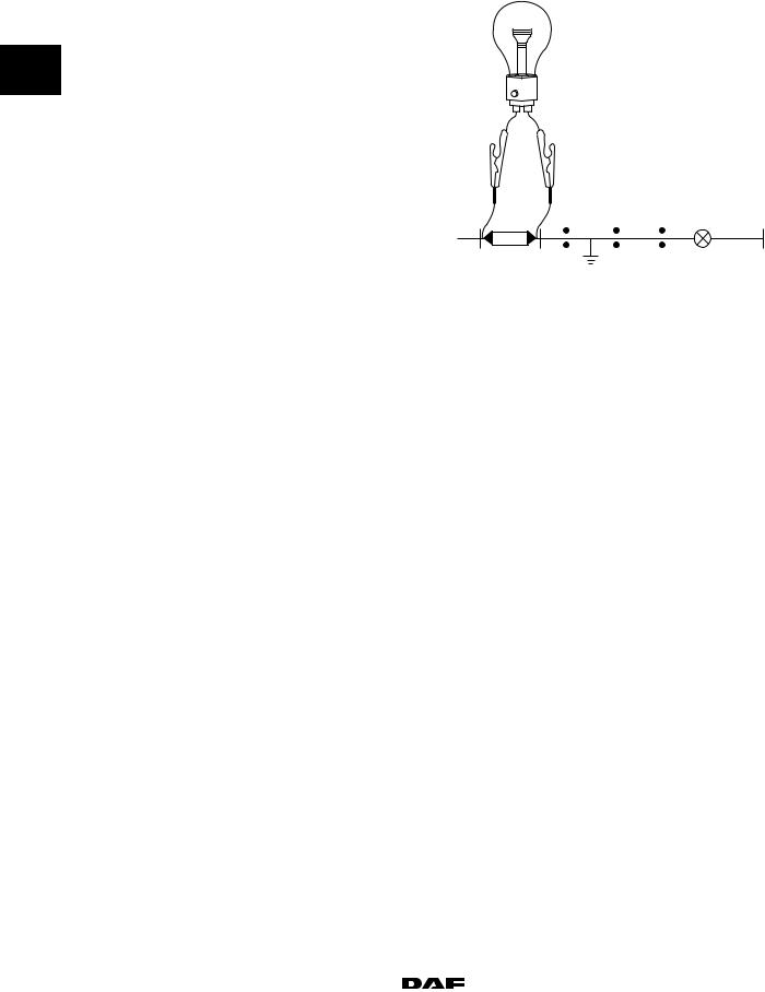
1.1 SHORT CIRCUITS |
|
A short circuit is caused by a positive wire shorting to earth somewhere. In most cases this will cause a fuse to blow.
1To remedy this failure, use a test lamp of approximately 70W. First check the diagram to see which consumers are connected to the fuse in question, and then switch them all off. Remove the fuse and connect the test lamp in its place. Now switch each of the consumers on and off one by one. If the lamp comes on very brightly when a consumer is switched on, the
fault is almost certainly in the wiring of that |
|
consumer. Now check the diagram to see via |
|
which connectors the consumer is connected. |
|
Now disconnect the first wiring connection (as |
|
seen from the fuse). |
|
If the lamp is still bright, the fault is between the |
|
fuse and this wiring connection. |
W 5 03 013 |
If, however, the lamp goes out, the fault is somewhere further on in the wiring.
Now reconnect the connectors and disconnect the next wiring connection. If the lamp is still bright, the failure is between these two wiring connections.
However, if the lamp goes out again, the fault-finding procedure must be continued. The faulty wiring section can be found in this way.
1-2 |
|
|
200520 |
|
|
||
|
https://www.truck-manuals.net/ |
||
5 |
DIAGNOSTICS |
|
CF65/75/85 Series ≥0E621376 |
Fault finding |
|
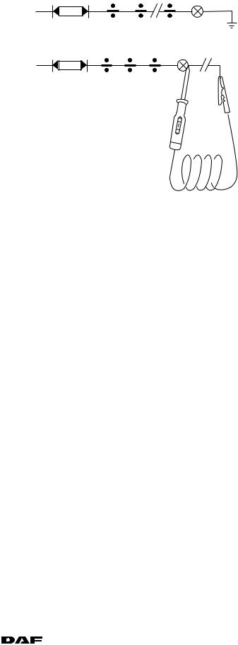
1.2 OPEN CIRCUIT |
|
|
Suppose a consumer is not functioning. The fault may be in the consumer itself, or there may be an open circuit in the wiring.
First switch on the consumer. Then check the consumer for voltage using a test lamp. If no voltage is found, first check whether the fuse is still intact.
If there is voltage at the fuse, check the wiring from the fuse to the consumer. This means every wiring connection must be checked. Stop at the first wiring connection that has no voltage. The open circuit will be between this connection and the previous one.
However, if there was a voltage at the consumer, there may still be an open circuit in the negative (earth) wiring. Check this using a test lamp.
Ensure that the relevant circuit is switched on. Connect one end of the test lamp to earth and the other end to the earth connection of the component to be checked.
If the test lamp lights up, the earth connection of the component is interrupted. If the test lamp does not light up, the earth connection will in many cases be in good condition.
If both the positive and negative connections are in good order, the consumer in question must be replaced.
W 5 03 015 |
1 |
||||
|
|||||
|
|
|
|
|
|
|
|
|
|
|
|
|
|
|
|
|
|
W 5 03 016
200520 |
|
|
|
1-3 |
|
https://www.truck-manuals.net/ |
|||||
|
|
||||
DIAGNOSTICS |
5 |
Fault finding |
CF65/75/85 Series ≥0E621376 |
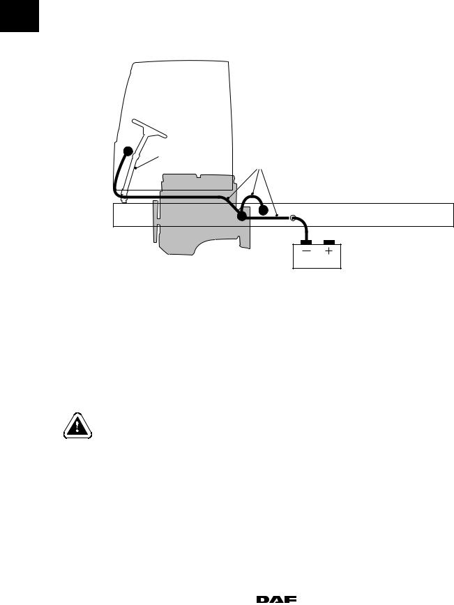
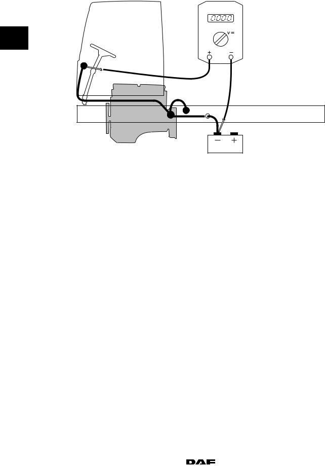
1.3 EARTHING PROBLEMS |
|
Earthing problems are mainly caused by corrosion between the contact surfaces of electrical connections.
1A poor earth connection of the main earth circuit (2) between cab and chassis may result in a current through the steering shaft (1).
1
2
E502316
To check this main earth connection, two complementary tests must be carried out.
-A current measurement using a current probe.
-A voltage loss measurement using a multimeter.
A current probe, which is a special tool (DAF no. 1453183), must be used for a current measurement; this measures the current through the steering shaft (1).
The current measurements have to be carried out while the cab is in the driving position.
1-4 |
|
|
200520 |
|
|
||
|
https://www.truck-manuals.net/ |
||

5 |
DIAGNOSTICS |
|
CF65/75/85 Series ≥0E621376 |
Fault finding |
|
INSPECTION 1, MEASURING THE SYSTEM
CURRENT
1.Open the grille.
2. |
Switch on vehicle ignition and as many |
|
|
|
|
consumers as possible, e.g.: |
1 |
|
|
|
- |
dipped beam |
1 |
|
|
- heater fan in position 4 |
|
||
|
- |
spotlights, etc. |
|
|
3. |
Use the current probe to check whether the |
|
|
|
|
power consumption through the battery |
|
|
|
|
cable at the battery is between 20 A and 40 |
|
|
|
|
A. Switch on extra consumers if this is not |
|
|
|
|
the case until the power consumption is |
|
|
|
|
between 20 A and 40 A. |
|
|
|
4. |
Then measure the system current through |
|
|
|
|
the steering shaft (1) using the probe. Make |
|
|
|
|
sure that the current probe is placed in the |
|
|
|
right position (direction of current) and its jaws are closed around the steering shaft.
5.Depending on the measured current value, the following actions need to be carried out:
E502267
200520 |
|
|
|
1-5 |
|
https://www.truck-manuals.net/ |
|||||
|
|
||||

|
|
DIAGNOSTICS |
5 |
|
|
|
|
Fault finding |
CF65/75/85 Series ≥0E621376 |
|
|
|
|
|
|
|
|
|
|
Measured |
Measures to be taken |
|
|
|
|
current value |
|
|
|
|
|
|
|
|
|
|
|
< 2.0 A |
- The main earth connections are in good order, end of inspection 1. Continue |
|
|
|
|
|
with inspection 2. |
|
|
1 |
|
≥ 2.0 A and |
- Inspect - and if necessary repair - all main earth connections from the cab to |
|
|
|
< 5.0 A |
the negative battery terminal between the following points: |
|
|
|
|
|
|
- battery earth and cab earth |
|
|
|
|
|
|
|
|
|
|
|
- cab earth and flywheel housing earth |
|
|
|
|
|
- flywheel housing earth and chassis earth |
|
|
|
|
|
- chassis earth and battery earth |
|
|
|
|
|
Note: |
|
|
|
|
|
A voltage loss measurement must be carried out to identify which earthing point |
|
|
|
|
|
is in poor condition. This measurement is described later on in this procedure. |
|
|
|
|
|
- The current value through the steering shaft must be less than 2.0 A after |
|
|
|
|
|
repair. Otherwise one or more earth connections are not yet in good order and |
|
|
|
|
|
the main earth connections must be inspected again and if necessary |
|
|
|
|
|
repaired. |
|
|
|
|
|
- If the current value is < 2.0 A, the main earth connections are in good order: |
|
|
|
|
|
end of inspection 1. Continue with inspection 2. |
|
|
|
|
≥ 5.0 A |
- Inspect - and if necessary repair - all main earth connections from the cab to |
|
|
|
|
|
the negative battery terminal between the following points: |
|
|
|
|
|
- battery earth and cab earth |
|
|
|
|
|
- cab earth and flywheel housing earth |
|
|
|
|
|
- flywheel housing earth and chassis earth |
|
|
|
|
|
- chassis earth and battery earth |
|
|
|
|
|
Note: |
|
|
|
|
|
A voltage loss measurement must be carried out to identify which earthing point |
|
|
|
|
|
is in poor condition. This measurement is described later on in this procedure. |
|
|
|
|
|
- The current value through the steering shaft must be less than 2.0 A after |
|
|
|
|
|
repair. Otherwise one or more main earth connections are not yet in good |
|
|
|
|
|
order and the earth connections must be inspected again and if necessary |
|
|
|
|
|
repaired. |
|
|
|
|
|
- If the current value is < 2.0 A, the earth connections are in good order. |
|
|
|
|
|
Note: |
|
|
|
|
|
A high current through the steering shaft can affect the mechanical condition of |
|
|
|
|
|
the steering shaft bearing. |
|
|
|
|
|
|
|
|
1-6 |
|
|
200520 |
|
|
||
|
https://www.truck-manuals.net/ |
||

5 |
|
DIAGNOSTICS |
|||
CF65/75/85 Series ≥0E621376 |
Fault finding |
|
|
||
INSPECTION 2, MEASURING THE STARTING |
|
|
|
|
|
CURRENT |
|
|
|
|
|
Measure the starting current through the |
|
|
|
|
|
steering shaft while starting, using the current |
|
|
|
|
|
probe. |
|
|
|
|
|
This measurement must be carried out with the |
|
|
|
|
|
|
|
|
1 |
||
probe’s “Max Hold” function. Make sure that the |
|
|
|
||
current probe is placed in the right position |
|
||||
(direction of current) and its jaws are closed |
|
|
|
|
|
|
|
|
|
||
around the steering shaft. |
|
|
|
|
|
|
|
|
|
|
|
Measured |
Measures to be taken |
|
|
|
|
current value |
|
|
|
|
|
|
|
|
|
||
< 5.0 A |
- Main earth connections are in good condition; end of inspection 2: vehicle |
|
|
|
|
|
is OK. |
|
|
|
|
≥ 5.0 A |
- Inspect - and if necessary repair - all main earth connections from the cab |
|
|
|
|
|
to the negative battery terminal between the following points: |
|
|
||
|
- battery earth and cab earth |
|
|
|
|
|
- cab earth and flywheel housing earth |
|
|
|
|
|
- flywheel housing earth and chassis earth |
|
|
|
|
|
- chassis earth and battery earth |
|
|
|
|
|
Note: |
|
|
|
|
|
A voltage loss measurement must be carried out to identify which earthing |
|
|
||
|
point is in poor condition. This measurement is described later on in this |
|
|
||
|
procedure. |
|
|
|
|
|
- The starting current value through the steering shaft must be less than 5.0 |
|
|
||
|
A after repair. Otherwise one or more main earth connections are not yet in |
|
|
||
|
good order and the main earth connections must be inspected again and if |
|
|
||
|
necessary repaired. |
|
|
|
|
|
- If the current value is < 5.0 A, the earth connections are in good order; |
|
|
||
|
end of inspection 2: vehicle is OK. |
|
|
|
|
|
|
|
|
|
|
200520 |
|
|
|
1-7 |
|
https://www.truck-manuals.net/ |
|||||
|
|
||||
DIAGNOSTICS |
5 |
Fault finding |
CF65/75/85 Series ≥0E621376 |
MEASURING VOLTAGE LOSS |
|
1
4
3
2
1
E502269
1 negative battery terminal
2flywheel housing
3chassis
4bulkhead lead-through connector
To find out whether a specific earthing point has a good earth connection, measure the voltage loss between the negative battery terminal and this earthing point.
The figure shown is an example; the actual course of the earth connection may differ somewhat depending on vehicle type and production date.
The consumers that were switched when the current was measured should now be switched on as well, i.e. the power consumption should be between 20 A and 40 A.
If the earth connection is good, the voltage loss should be less than 0.5 V.
1-8 |
|
|
200520 |
|
|
||
|
https://www.truck-manuals.net/ |
||

5 |
DIAGNOSTICS |
|
|
CF65/75/85 Series ≥0E621376 |
Batteries |
|
|
2. BATTERIES |
|
|
|
2.1 FAULT-FINDING TABLE |
|
|
|
|
|
|
|
SYMPTOM: NEW BATTERY HEATS UP CONSIDERABLY DURING FILLING |
|
|
|
|
1 |
||
|
|
|
|
Possible cause |
Remedy |
|
|
|
|
||
|
|
|
|
Inadequate formation because of storage in |
Allow to cool |
|
|
|
|
||
unsuitable or damp conditions over a long period |
Charge fully |
|
|
|
Check the relative density |
|
|
|
|
|
|
|
|
||
SYMPTOM: BATTERY ACID LEAKING FROM THE PLUG HOLES |
|
|
|
|
|
|
|
Possible cause |
Remedy |
|
|
|
|
|
|
Battery overfilled |
Siphon off some of the fluid |
|
|
|
|
|
|
Overcharging |
Check the charger and repair if necessary |
|
|
|
|
|
|
|
|
||
SYMPTOM: ELECTROLYTE LEVEL TOO LOW |
|
|
|
|
|
|
|
Possible cause |
Remedy |
|
|
|
|
|
|
Leaking battery |
Replace the battery |
|
|
Excessive gas development due to charging |
Check/repair the charger |
|
|
current being set too high |
|
|
|
|
|
||
SYMPTOM: RELATIVE DENSITY TOO LOW (<1.240) |
|
|
|
STARTING TROUBLE |
|
|
|
Possible cause |
Remedy |
|
|
|
|
|
|
Power consumer left on by mistake |
Charge the battery |
|
|
Insufficient charging |
Check/repair the charger |
|
|
Short circuit in the charging circuit |
Check the charging circuit |
|
|
|
|
|
|
|
|
||
SYMPTOM: DENSITY IS TOO HIGH (>1.290) |
|
|
|
|
|
|
|
Possible cause |
Remedy |
|
|
|
|
|
|
Topped up with acid instead of distilled water |
Siphon off the fluid and fill with distilled water |
|
|
|
If necessary, repeat this after mixing (charging) |
|
|
|
|
|
|
200520 |
|
|
|
2-1 |
|
https://www.truck-manuals.net/ |
|||||
|
|
||||

|
|
DIAGNOSTICS |
5 |
|
|
|
|
Batteries |
CF65/75/85 Series ≥0E621376 |
|
|
|
|
|
|
|
|
|
|
|
SYMPTOM: STARTING TROUBLE |
|
|
|
|
|
POOR STARTING TEST RESULT |
|
|
|
|
|
POWER FAILS UNDER LOAD |
|
|
|
|
|
|
|
|
|
|
|
Possible cause |
Remedy |
|
|
|
|
|
|
|
1 |
|
- |
Discharged battery |
Charge the battery |
|
|
|
|
|||
|
|
- Worn battery (plates corroded and worn |
Replace the battery |
|
|
|
|
|
away) |
|
|
|
|
- Defective battery (“dead cell”) |
Replace the battery |
|
|
|
|
- |
Battery too small |
Replace with battery of a higher capacity |
|
|
|
- Battery sulphated (plates have hardened) |
Replace the battery |
|
|
|
|
|
|
|
|
|
|
|
|
|
|
|
|
|
SYMPTOM: BURNT-IN BATTERY TERMINALS |
|
|
|
|
|
|
|
|
|
|
|
Possible cause |
Remedy |
|
|
|
|
|
|
|
|
|
- Clamps not securely fitted, or poor contact |
Have the battery terminals repaired, fit the |
|
|
|
|
|
|
clamps properly or replace the clamps if |
|
|
|
|
|
necessary |
|
|
|
|
|
|
|
|
|
|
|
|
|
|
|
|
SYMPTOM: 1 OR 2 CELLS BUBBLE EXCESSIVELY UNDER HIGH LOADS (STARTING OR |
|
|
|
|
|
STARTING TEST) |
|
|
|
|
|
|
|
|
|
|
|
Possible cause |
Remedy |
|
|
|
|
|
|
|
|
|
- |
Defective cells |
Replace the battery |
|
|
|
- |
Leaking cell partition |
Replace the battery |
|
|
|
|
|
|
|
|
|
|
|
|
|
|
|
|
SYMPTOM: BATTERY DISCHARGES VERY FAST (DOES NOT RETAIN POWER) |
|
|
|
|
|
|
|
|
|
|
|
Possible cause |
Remedy |
|
|
|
|
|
|
|
|
|
- |
Insufficient charging |
Check the charging. Is the charging time (driving |
|
|
|
|
|
time) sufficient? |
|
|
|
- Short circuit in charging circuit |
Check the charging circuit |
|
|
|
|
- Major self-discharging, for example due to |
Clean the battery |
|
|
|
|
|
contamination |
|
|
|
|
- Battery sulphated (on examining the plates, |
Replace the battery |
|
|
|
|
|
they are found to be hard and, in some |
|
|
|
|
|
cases, whitened) |
|
|
|
|
|
|
|
|
|
|
|
|
|
|
|
|
|
SYMPTOM: SHORT BATTERY LIFE |
|
|
|
|
|
|
|
|
|
|
|
Possible cause |
Remedy |
|
|
|
|
|
|
|
|
|
- Wrong type of battery chosen (for example in |
Install Super Heavy Duty or semi-traction battery |
|
|
|
|
|
the case of tail lifts) |
|
|
|
|
- Often too deeply discharged |
Intermediate charging with rectifier |
|
|
|
|
- No recharging after deep discharge |
Always charge the battery after deep discharge |
|
|
|
|
|
(white deposits) |
|
|
|
|
|
|
|
|
2-2 |
|
|
200520 |
|
|
||
|
https://www.truck-manuals.net/ |
||
5 |
|
DIAGNOSTICS |
||
CF65/75/85 Series ≥0E621376 |
Batteries |
|
|
|
|
|
|
|
|
|
SYMPTOM: BATTERY HOT DURING OPERATION WITH EXCESSIVE WATER CONSUMPTION |
|
|
|
|
|
|
|
|
|
Possible cause |
Remedy |
|
|
|
|
|
|
|
- |
Overcharging or |
Check the charger (voltage regulator) |
|
|
- charging voltage too high |
|
|
|
|
|
|
1 |
||
|
|
|
|
|
|
|
|
||
|
SYMPTOM: BATTERY HAS EXPLODED |
|||
|
|
|
||
|
|
|
||
|
|
|
|
|
|
Possible cause |
Remedy |
|
|
|
|
|
|
|
- Fire or sparks during or just after charging |
Ensure good ventilation and exercise due |
|
|
|
|
|
caution as regards fire and sparks |
|
|
- |
Short-circuiting by tools |
Be careful where tools are put down |
|
|
- Internal defect (loose connection) |
Replace the battery |
|
|
|
|
|
|
|
|
|
|
|
||
|
SYMPTOM: DEFECTIVE ALTERNATOR AND/OR DIODES (RADIO AND OTHER |
|
|
|
|
POLARITY-SENSITIVE EQUIPMENT NOT WORKING) |
|
|
|
|
|
|
|
|
|
Possible cause |
Remedy |
|
|
|
|
|
|
|
- Reversed battery polarity or incorrect |
Discharge the battery and charge in the correct |
|
|
|
|
charging |
direction |
|
|
|
|
If necessary, replace the battery |
|
|
|
|
|
|
|
|
|
|
||
|
SYMPTOM: BATTERY IS INACTIVE (NO VOLTAGE) |
|
|
|
|
|
|
|
|
|
Possible cause |
Remedy |
|
|
|
|
|
|
|
- |
Internal open circuit |
Replace the battery |
|
|
- Battery very deeply discharged |
Charge the battery and test it; replace if |
|
|
|
|
|
necessary |
|
|
|
|
|
|
|
200520 |
|
|
|
2-3 |
|
https://www.truck-manuals.net/ |
|||||
|
|
||||

DIAGNOSTICS |
5 |
Batteries |
CF65/75/85 Series ≥0E621376 |
2.2 SERVICE LIFE |
|
The service life of a battery is significantly shortened if it used “cyclically”.
This means that the batteries are used a lot
1without being charged.
For example when using a tail lift, cab heater, microwave oven or cooler box.
This is why batteries in commercial vehicles and vehicles used for international transport often fail prematurely (within 1.5 years).
The battery must be charged whenever the voltage measured across the battery falls below 12.5V. If the battery is not charged, the “sulphating process” will begin.
This is a chemical reaction in the battery that produces lead sulphate. Lead sulphate adheres to the battery plates and can cause short-circuiting between the plates, reducing the capacity of the battery.
However, most lead sulphate breaks down when the battery is recharged.
If a battery is used (discharged) while it is not being charged by the alternator, short-circuiting between the battery plates will occur sooner. This reduces the capacity and consequently the service life of the battery.
2-4 |
|
|
200520 |
|
|
||
|
https://www.truck-manuals.net/ |
||

5 |
DIAGNOSTICS |
|
|
CF65/75/85 Series ≥0E621376 |
Alternator |
|
|
3. ALTERNATOR |
|
|
|
3.1 FAULT-FINDING TABLE |
|
|
|
|
|
|
|
SYMPTOM: ALTERNATOR NOT PRODUCING POWER WHEN IDLING |
|
|
|
|
1 |
||
|
|
|
|
Possible cause |
Remedy |
|
|
|
|
||
|
|
|
|
Open circuit in connection 15 on alternator |
Repair connection 15 |
|
|
|
|
||
Connection 15 on alternator short-circuited to |
Repair connection 15 |
|
|
earth |
|
|
|
Internal defect |
Replace regulator |
|
|
|
|
|
|
|
|
||
SYMPTOM: ALTERNATOR WARNING (YELLOW) |
|
|
|
|
|
|
|
Possible cause |
Remedy |
|
|
|
|
|
|
Open circuit in “S” connection |
Measure the regulated alternator voltage with as |
|
|
|
many consumers as possible switched on and |
|
|
|
with the engine turning above idling speed |
|
|
Open circuit in “L” connection |
Check/repair wiring |
|
|
Open circuit in connection 15 |
Increase the engine speed to approx. 1500 rpm. |
|
|
|
If voltage is now present, check connection 15 |
|
|
|
on the alternator |
|
|
Voltage difference between “B+” and |
Check all contacts between alternator and |
|
|
“S” connections is greater than 2.5V |
batteries (contact resistors). |
|
|
|
Internal battery resistance too high |
|
|
Voltage too low <16V |
Check alternator drive. Check wiring on contact |
|
|
|
resistors. Check regulated voltage |
|
|
Open circuit in voltage regulator |
Replace voltage regulator |
|
|
|
|
|
|
|
|
||
SYMPTOM: ALTERNATOR VOLTAGE HIGH (RED) |
|
|
|
|
|
|
|
Possible cause |
Remedy |
|
|
|
|
|
|
Voltage too high > 31V |
Measure voltage |
|
|
Internal defect |
Replace regulator/alternator |
|
|
|
|
|
|
200520 |
|
|
|
3-1 |
|
https://www.truck-manuals.net/ |
|||||
|
|
||||

DIAGNOSTICS |
5 |
Alternator |
CF65/75/85 Series ≥0E621376 |
1
3-2 |
|
|
200520 |
|
|
||
|
https://www.truck-manuals.net/ |
||

5 |
DIAGNOSTICS |
|
|
CF65/75/85 Series ≥0E621376 |
Xenon lighting |
|
|
4. XENON LIGHTING |
|
|
|
4.1 FAULT-FINDING TABLE |
|
|
|
|
|
|
|
SYMPTOM: XENON LIGHTING NOT WORKING ON ONE SIDE |
|
|
|
|
1 |
||
|
|
|
|
Possible cause |
Remedy |
|
|
|
|
||
|
|
|
|
Faulty dipped beam fuse |
Check fuse |
|
|
|
|
||
No power to the ballast unit on the faulty side |
Check the power supply to the ballast unit |
|
|
Faulty xenon bulb |
Replace xenon bulb |
|
|
Faulty ignition unit |
Replace ignition unit |
|
|
Faulty wiring between the ballast unit and the |
Check the wiring |
|
|
ignition unit |
|
|
|
Faulty ballast unit |
Replace ballast unit |
|
|
Ignition unit connector not connected properly |
Check connector |
|
|
|
|
|
|
|
|
||
SYMPTOM: XENON LIGHTING NOT WORKING ON BOTH SIDES |
|
|
|
|
|
|
|
Possible cause |
Remedy |
|
|
|
|
|
|
Faulty fuse |
Check fuse |
|
|
Faulty light switch (C622) |
Check light switch |
|
|
Faulty relay (G001) |
Check relay |
|
|
Faulty wiring |
Check the wiring |
|
|
|
|
|
|
|
|
||
SYMPTOM: COLOUR DIFFERENCE AFTER NEW BULB IS FITTED |
|
|
|
|
|
|
|
Possible cause |
Remedy |
|
|
|
|
|
|
Bulb of a different make fitted |
Bulbs of the same make should preferably be |
|
|
|
fitted on both left and right |
|
|
200520 |
|
|
|
4-1 |
|
https://www.truck-manuals.net/ |
|||||
|
|
||||

DIAGNOSTICS |
5 |
Xenon lighting |
CF65/75/85 Series ≥0E621376 |
1
4-2 |
|
|
200520 |
|
|
||
|
https://www.truck-manuals.net/ |
||

5 |
|
|
COMPONENTS |
|
||
CF65/75/85 series ≥0E621376 |
|
Contents |
|
|
||
CONTENTS |
|
|
|
|
||
|
|
|
Page |
Date |
|
|
1. |
GENERAL . . . . . . . . . . . . . . . . . . . . . . . . . . . . . . . . . . . . . . . . . . . . . . . . . . . . . . . . . |
. . . 1-1 . . |
. . 200404 |
|
|
|
|
1.1 |
Multimeter . . . . . . . . . . . . . . . . . . . . . . . . . . . . . . . . . . . . . . . . . . . . . . . . . . . . |
. . . 1-1 . . |
. . 200404 |
|
|
|
1.2 |
Scopemeter . . . . . . . . . . . . . . . . . . . . . . . . . . . . . . . . . . . . . . . . . . . . . . . . . . . |
. . . 1-2 . . |
. . 200404 |
|
|
|
1.3 |
Signal measurements . . . . . . . . . . . . . . . . . . . . . . . . . . . . . . . . . . . . . . . . . . |
. . . 1-3 . . |
. . 200404 |
|
|
2. |
DESCRIPTION OF COMPONENTS . . . . . . . . . . . . . . . . . . . . . . . . . . . . . . . . . . . |
. . . 2-1 . . |
. . 200404 |
|
|
|
|
2 |
|||||
|
2.1 |
Inductive sensor . . . . . . . . . . . . . . . . . . . . . . . . . . . . . . . . . . . . . . . . . . . . . . . |
. . . 2-1 . . |
. . 200404 |
|
|
|
2.2 |
Vehicle speed sensor . . . . . . . . . . . . . . . . . . . . . . . . . . . . . . . . . . . . . . . . . . . |
. . . 2-2 . . |
. . 200404 |
|
|
|
2.3 |
Temperature sensors . . . . . . . . . . . . . . . . . . . . . . . . . . . . . . . . . . . . . . . . . . . |
. . . 2-4 . . |
. . 200404 |
|
|
|
|
|
||||
|
2.4 |
Fluid level sensors . . . . . . . . . . . . . . . . . . . . . . . . . . . . . . . . . . . . . . . . . . . . . |
. . . 2-6 . . |
. . 200404 |
|
|
|
2.5 |
Pressure sensors . . . . . . . . . . . . . . . . . . . . . . . . . . . . . . . . . . . . . . . . . . . . . . |
. . . 2-7 . . |
. . 200404 |
|
|
|
2.6 |
Alternator . . . . . . . . . . . . . . . . . . . . . . . . . . . . . . . . . . . . . . . . . . . . . . . . . . . . . |
. . . 2-8 . . |
. . 200404 |
|
|
|
2.7 |
Proximity sensors . . . . . . . . . . . . . . . . . . . . . . . . . . . . . . . . . . . . . . . . . . . . . . |
. . . 2-10 . |
. . 200404 |
|
|
|
2.8 |
Steering column switch . . . . . . . . . . . . . . . . . . . . . . . . . . . . . . . . . . . . . . . . . |
. . . 2-11 . |
. . 200404 |
|
|
3. DIAGNOSTICS . . . . . . . . . . . . . . . . . . . . . . . . . . . . . . . . . . . . . . . . . . . . . . . . . . . . . . . . 3-1 . . . . 200404 3.1 Diagnostics in electrical systems . . . . . . . . . . . . . . . . . . . . . . . . . . . . . . . . . . . . 3-1 . . . . 200404
200404 |
|
|
|
1 |
|
https://www.truck-manuals.net/ |
|||||
|
|
||||

COMPONENTS |
5 |
Contents |
CF65/75/85 series ≥0E621376 |
2
2 |
|
|
200404 |
|
https://www.truck-manuals.net/ |
||
5 |
COMPONENTS |
|
CF65/75/85 series ≥0E621376 |
General |
|
1. GENERAL
1.1 MULTIMETER
Various measurement options can be selected on the Fluke 87 multimeter.
Units of measurement
The multimeter should be set to the range for the unit of measurement required.
For example, voltage range, current range, or resistance range.
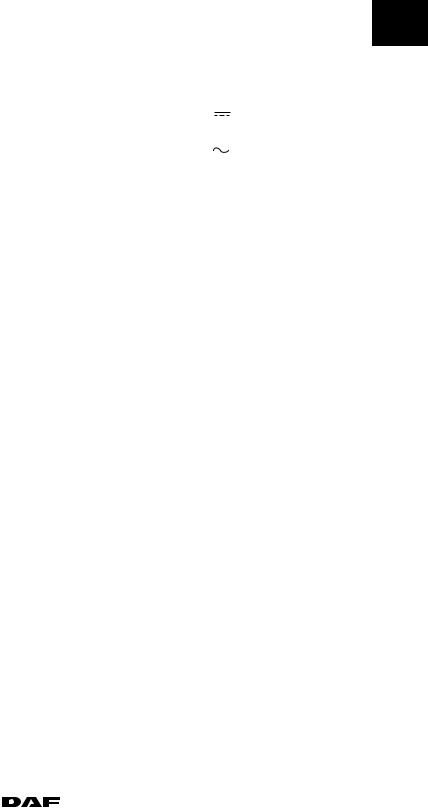
The units of measurement are indicated by symbols on the meter. The following symbols are used:
1.DC voltage
2.AC voltage
3.DC current
4.AC current
5.Resistance
6.Duty cycle
7.Frequency
2
1DCV - V
2ACV - V
3DCA - A
4ACA -A
5Ohm -
6%
7 Hz
W 5 01 004
200404 |
|
|
|
1-1 |
|
https://www.truck-manuals.net/ |
|||||
|
|
||||

COMPONENTS |
5 |
General |
CF65/75/85 series ≥0E621376 |
1.2 SCOPEMETER |
|
Diagnostics in modern electronic systems is becoming steadily more complex.
Using a multimeter on its own is not always sufficient to diagnose a fault.
The scopemeter allows complex signals to be measured.
2Practical examples of complex signals are:
-PWM signals
-signal deformation
-CAN-bus-signals
1-2 |
|
|
200404 |
|
|
||
|
https://www.truck-manuals.net/ |
||
 Loading...