

Daewoo DSA-095L, DSA-125L, DSA-125P, DSA-185L, DSA-185P Service Manual
...
Manual de servicio
Split Acondicionador de Aire
Modelo:

CONTENTS
1. Specifications..........................................................................................................2
2. Outline and Dimensions.........................................................................................6
3. Operation ..............................................................................................................14
4. Wiring Diagram.....................................................................................................25
5. Control Block Diagram.........................................................................................28
6. Electric Circuit Diagram........................................................................................31
7. Trouble Shooting..................................................................................................33
8. PCB Driving Description.......................................................................................39
9. Key Components of Electronic Circuit.................................................................63
10. Disassembly Instructions .....................................................................................66
1) Indoor Unit........................................................................................................66
2) Outdoor Unit.....................................................................................................70
3) Exploded Diagram (Indoor Unit)......................................................................73
4) Exploded Diagram (Outdoor Unit)...................................................................81
5) Control Box Assembly......................................................................................89
Contents
2
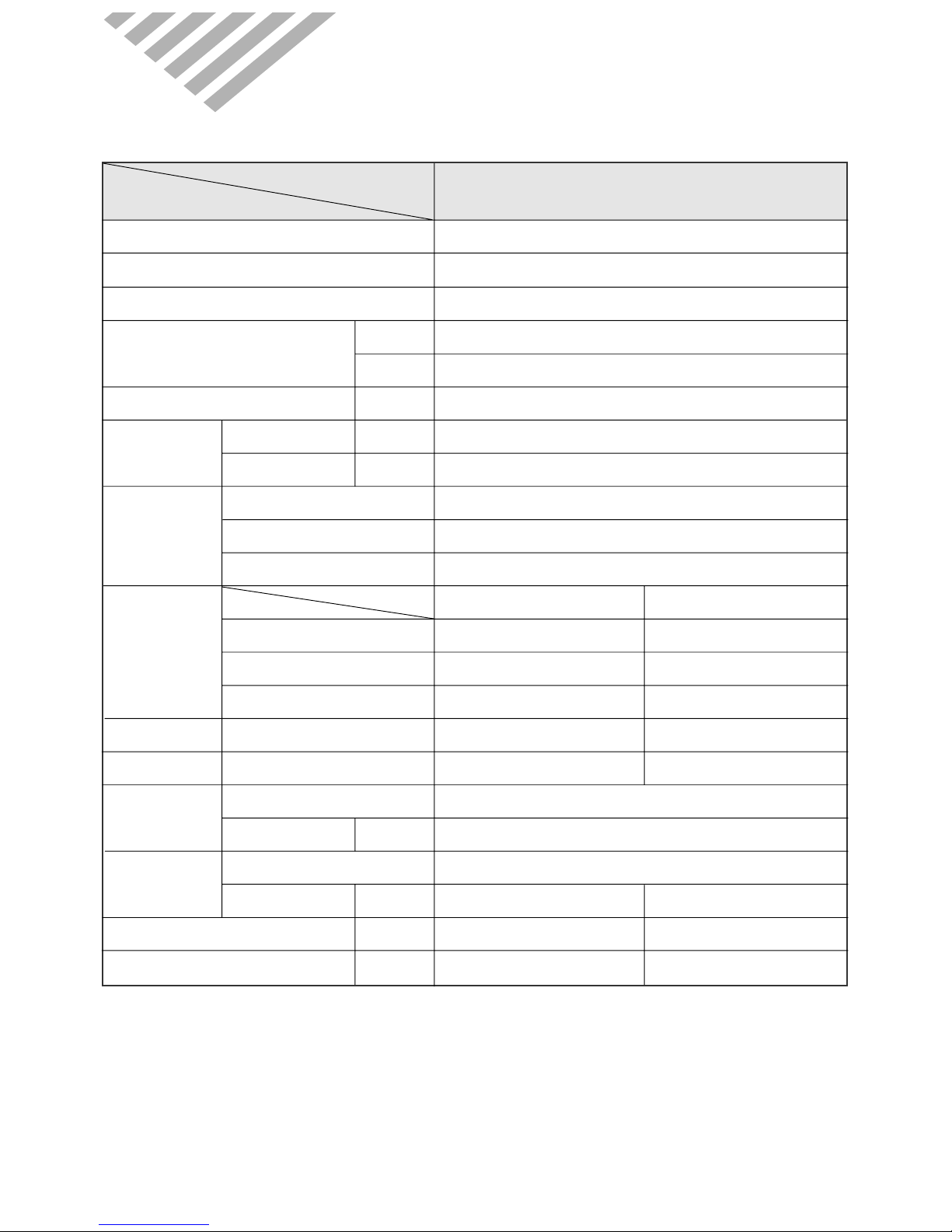
MODEL
DSA-095L
ITEM
Function Cooling
Class T1
Power AC 230V/ 60Hz
Capacity KJ/h 9,000
Btu/h 8,531
Dehumidification l/h 1.1
Running Current A 3.6
Power Input W 800
Type Rotary
Model QK125KB✳(LGE)
Capacitor 25µF / 400VAC
Indoor Unit Outdoor Unit
Type Cross flow fan Propeller fan
Capacitor 1.0µF 400VAC 2.0µF 400VAC
Motor Model Number YDK-8-4A(Xiang Ming) YDK-35-6A(Xiang Ming)
Sound Level (Hi) dB(A) 39 48
Fan Speed (Hi) RPM 1,350 880
Control Capillary
Charge Q'ty g 680
Type Flare
OD
(Liquid/Suction)
in(mm) 1/4 (6.35) 3/8 (9.52)
Dimensions (W x H x D) mm 750 x 245 x 179 654 x 549 x 256
Net Weight kg 7.0 34
Electrical
Data
Compressor
Fan
Motor
Refrigerant
(R22)
Connection
◆DSA-095L
1. SPECIFICATIONS
3
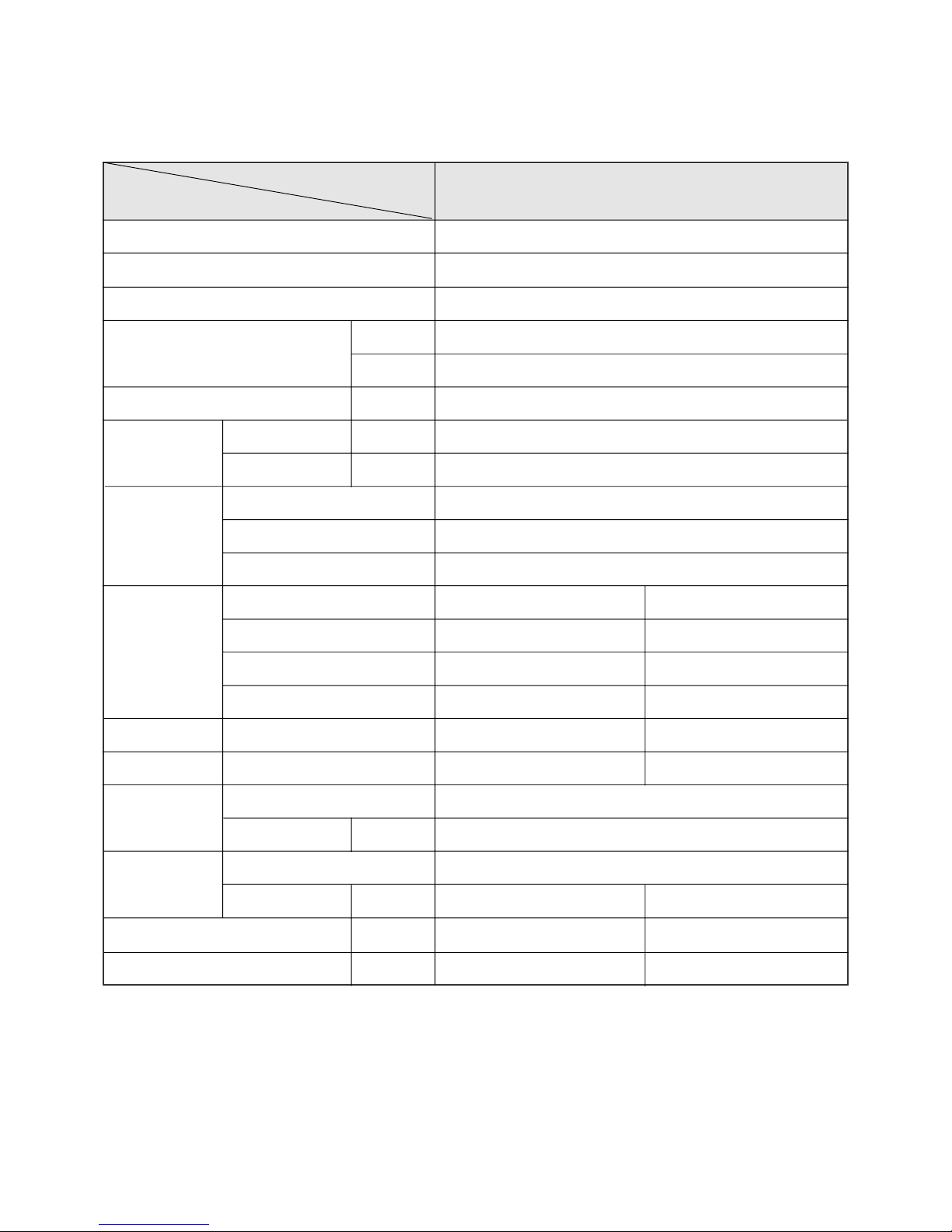
MODEL
DSA-125L, 125P
ITEM
Function Cooling
Class T1
Power AC 230V/ 60Hz
Capacity KJ/h 12,500
Btu/h 11,848
Dehumidification l/h 1.35
Running Current A 4.7
Power Input W 1,010
Type Rotary
Model QK156KA✳ (LGE)
Capacitor 35µF/ 370VAC
Division Indoor Unit Outdoor Unit
Type Cross flow fan Propeller fan
Capacitor 1.2µF 400VAC 3µF 400VAC
Motor Model Number RP-13B(Welling) YDK-50-6A(Xiang Ming)
Sound Level (Hi) dB(A) 42 52
Fan Speed (Hi) RPM 1,300 870
Control Capillary
Charge Q'ty g 1,000
Type Flare
OD
(Liquid/Suction)
in(mm) 1/4 (6.35) 3/8 (9.52)
Dimensions (W x H x D) mm 815 x 285 x 195 800 x 615 x 320
Net Weight kg 9.2 50
Electrical
Data
Compressor
Fan
Motor
Refrigerant
(R22)
Connection
◆DSA-125L, 125P
4
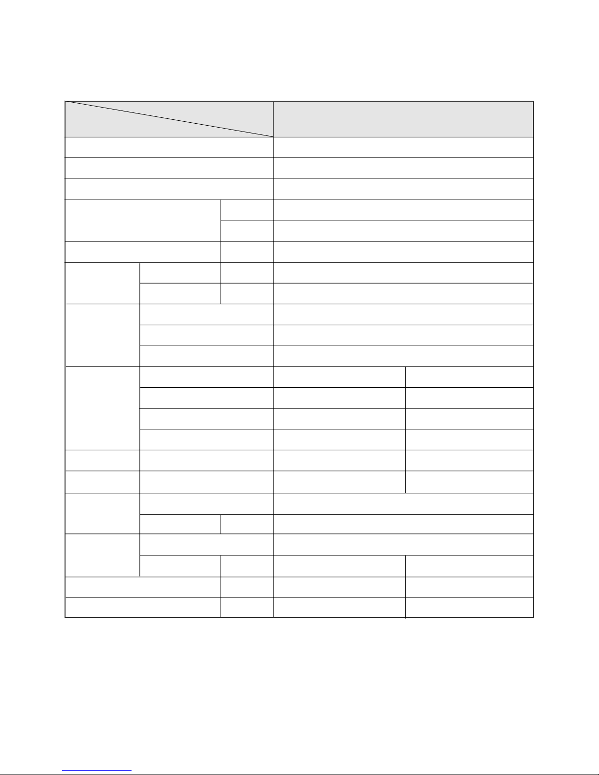
MODEL
DSA-185L, 185P
ITEM
Function Cooling
Class T1
Power AC 230V/ 60Hz
Capacity
KJ/h 17,500
Btu/h 16,588
Dehumidification l/h 2.0
Running Current A 7.2
Power Input W 1,620
Type Rotary
Model QJ250KA✳(LGE)
Capacitor 35µF/ 370VAC
Division Indoor Unit Outdoor Unit
Type Cross flow fan Propeller fan
Capacitor 1.2µF 400VAC 3µF 400VAC
Motor Model Number YDK-20-4A(Xiang Ming) YDK-50-6A(Xiang Ming)
Sound Level (Hi) dB(A) 48.1 56
Fan Speed (Hi) RPM 1,370 870
Control Capillary
Charge Q'ty g 1,070
Type Flare
OD
(Liquid/Suction)
in(mm) 1/4 (6.35) 1/2 (12.7)
Dimensions (W x H x D) mm 1035 x 322 x 205 800 x 615 x 320
Net Weight kg 11.7 50
Electrical
Data
Compressor
Fan
Motor
Refrigerant
(R-22)
Connection
◆DSA-185L, 185P
5
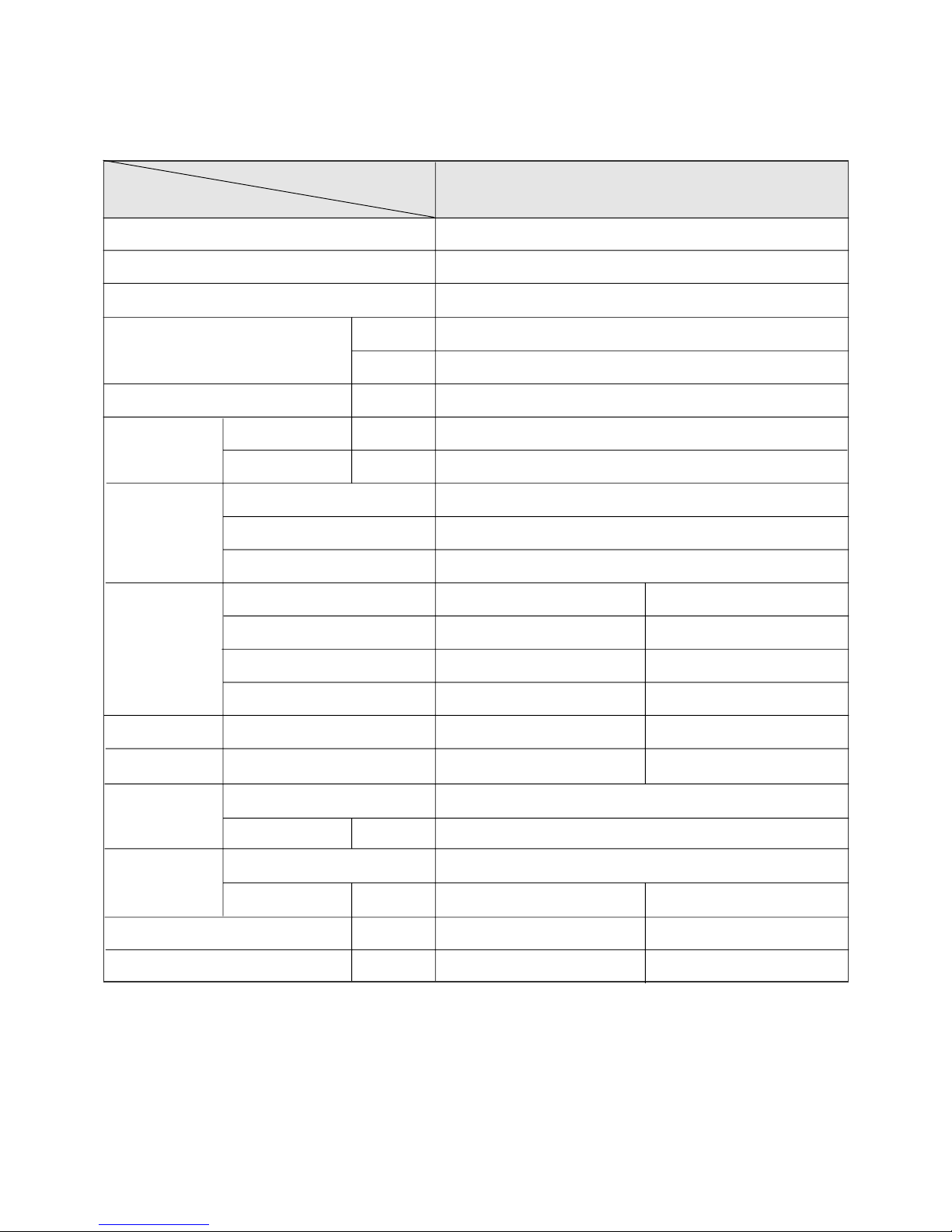
MODEL
DSA-245L, 245P
ITEM
Function Cooling
Class T1
Power AC 230V/ 60Hz
Capacity
KJ/h 23,500
Btu/h 22,275
Dehumidification l/h 2.7
Running Current A 10.0
Power Input W 2,220
Type Rotary
Model QP325KBB (LGE)
Capacitor 40µF/ 400VAC
Division Indoor Unit Outdoor Unit
Type Cross flow fan Propeller fan
Capacitor 1.2µF 400VAC 3µF 400VAC
Motor Model Number IC-9430DWKF7A(Sung shin) A2929GS010(DMI)
Sound Level (Hi) dB(A) 48.5 57
Fan Speed (Hi) RPM 1,300 950
Control Capillary
Charge Q'ty g 1,850
Type Flare
OD
(Liquid/Suction)
in(mm) 3/8 (9.52) 5/8 (15.9)
Dimensions (W x H x D) mm 1080 x 298 x 200 872 x 675 x 325
Net Weight kg 14.7 64
Electrical
Data
Compressor
Fan
Motor
Refrigerant
(R-22)
Connection
◆DSA-245L, 245P

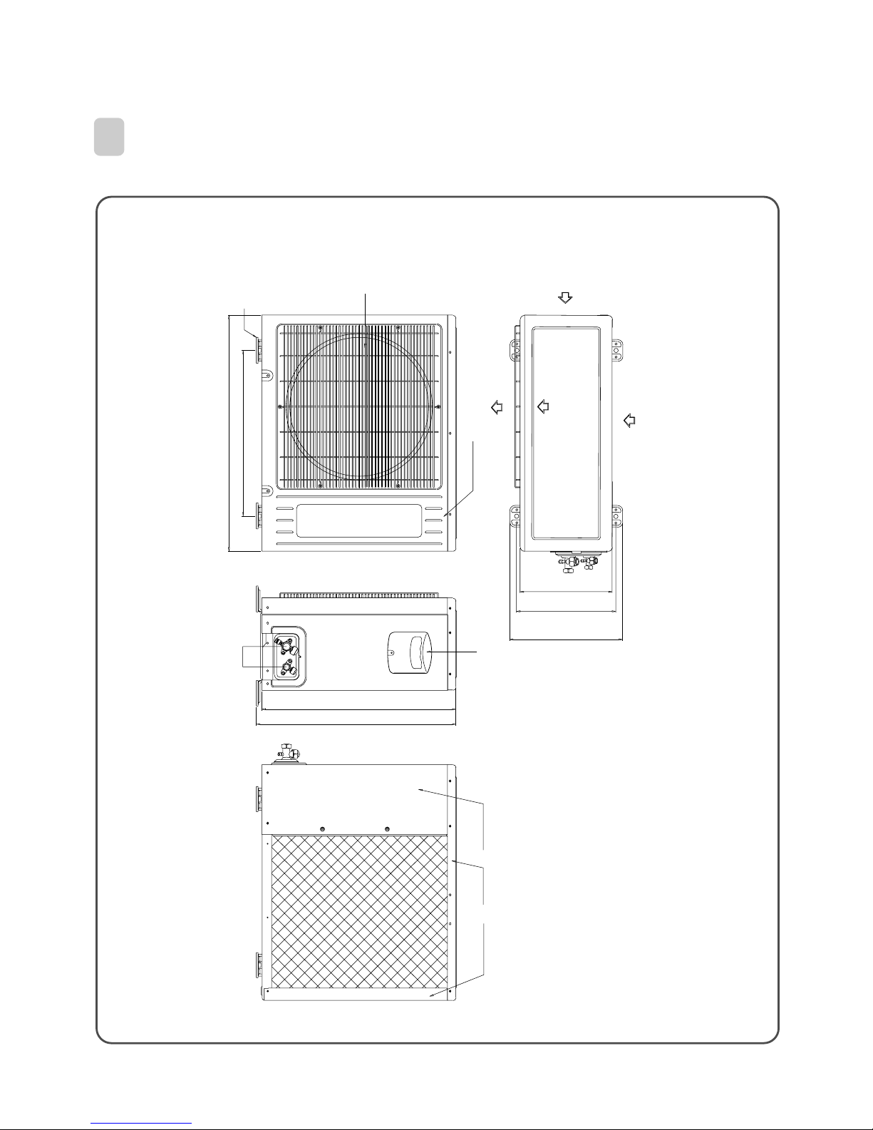
6
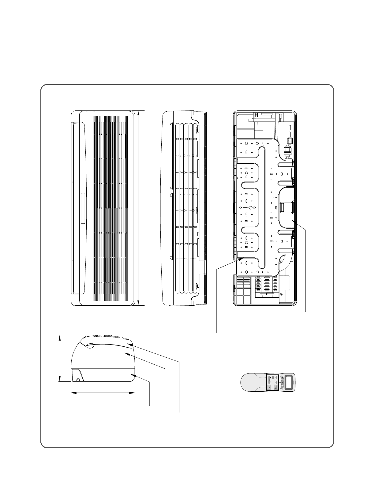
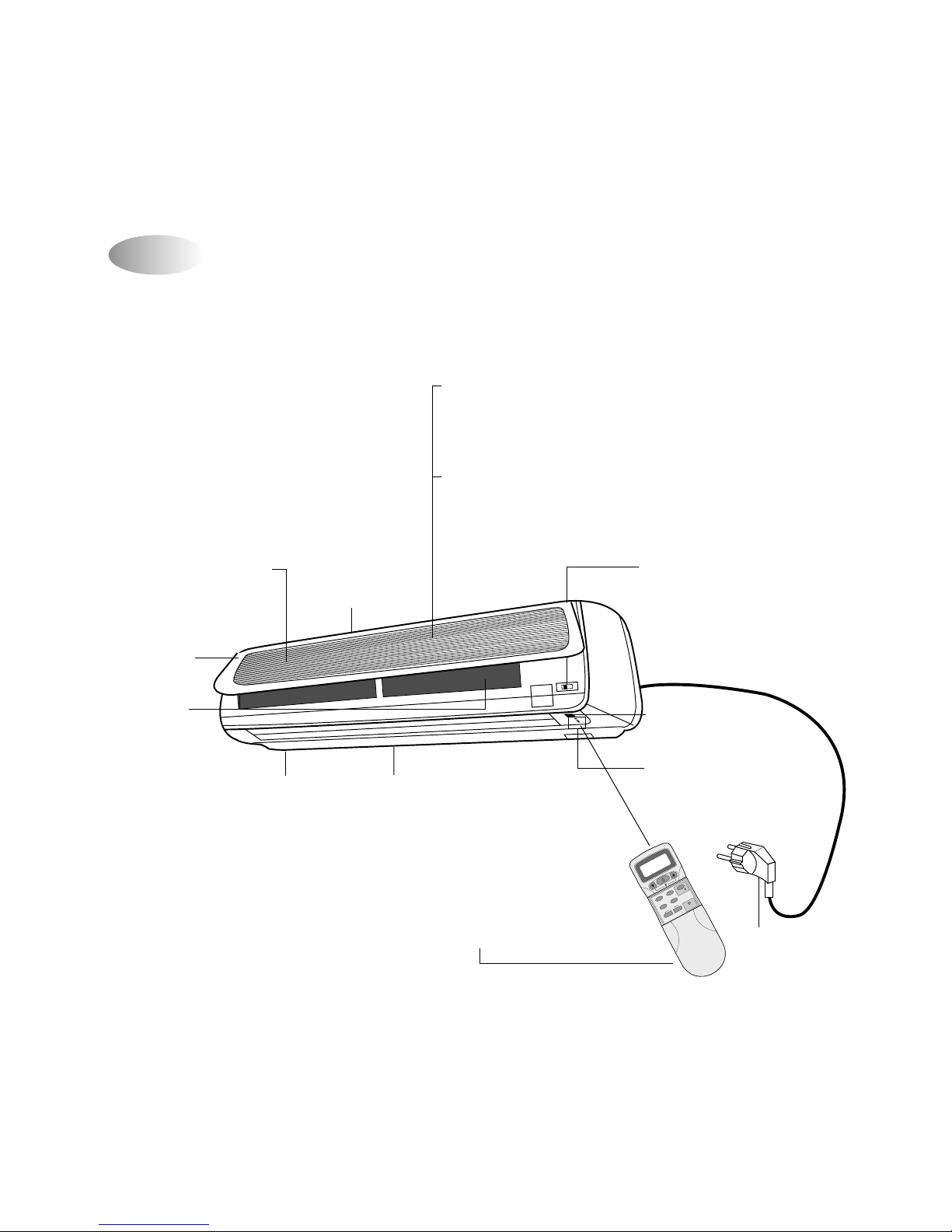
750
Plate Mounting
REMOCON
Connecting Pipe
Grille Insert
179
245
REMOTE CONTROLLER
Frame Grille
Body
Plate Mounting
2. OUTLINE AND DIMENSIONS
1
INDOOR UNIT
◆DSA-095L
MODE
SLEEP
ON/OFF
TIMER
ENTER/
CANCEL
FAN SPEED
TURBO/MILD
FAN DIR.
REMOCON
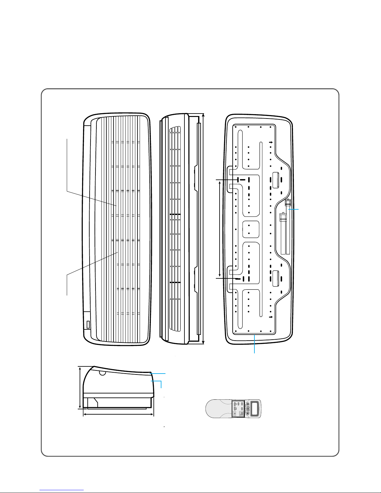
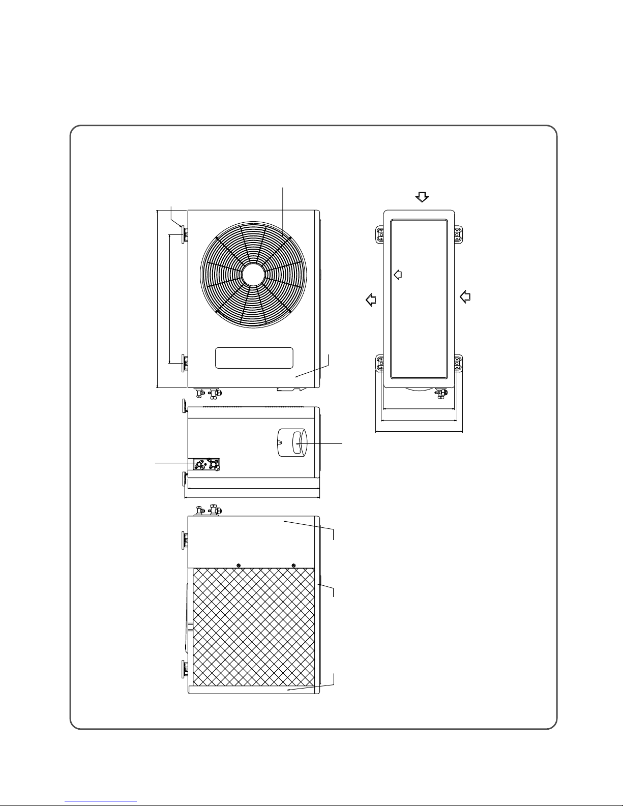
7
Insert Grille
Frame Grille
Body
Connecting Pipe
Plate Mounting
815
195
285
◆DSA-125L, 125P
MODE
SLEEP
ON/OFF
TIMER
ENTER/
CANCEL
FAN SPEED
TURBO/MILD
FAN DIR.
REMOCON
8
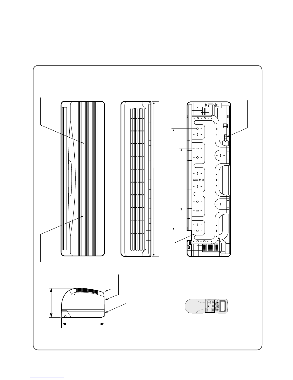
◆ DSA-185L, 185P
1035
205
322
453
¿‹ Æ˘˜ ˙`
”fi `⁄˘˙
`⁄„«…–‚fi‚ ˜
‰˙‡»– ‚Ø– ‚–
‰˙‡»– ‚ ˆ…
Connecting Pipe
Filter-L
Filter-R
Grille Insert
Body
Plate
Mounting
453
1035
MODE
SLEEP
ON/OFF
TIMER
ENTER/
CANCEL
FAN SPEED
TURBO/MILD
FAN DIR.
REMOCON
9
Connecting Pipe
Body
Frame Grille
Grille Insert
Plate Mounting
430
710
1080
Filter-L Filter-R
REMOCON
◆DSA-245L, 245P
200
298
MODE
SLEEP
ON/OFF
TIMER
ENTER/
CANCEL
FAN SPEED
TURBO/MILD
FAN DIR.
REMOCON
10
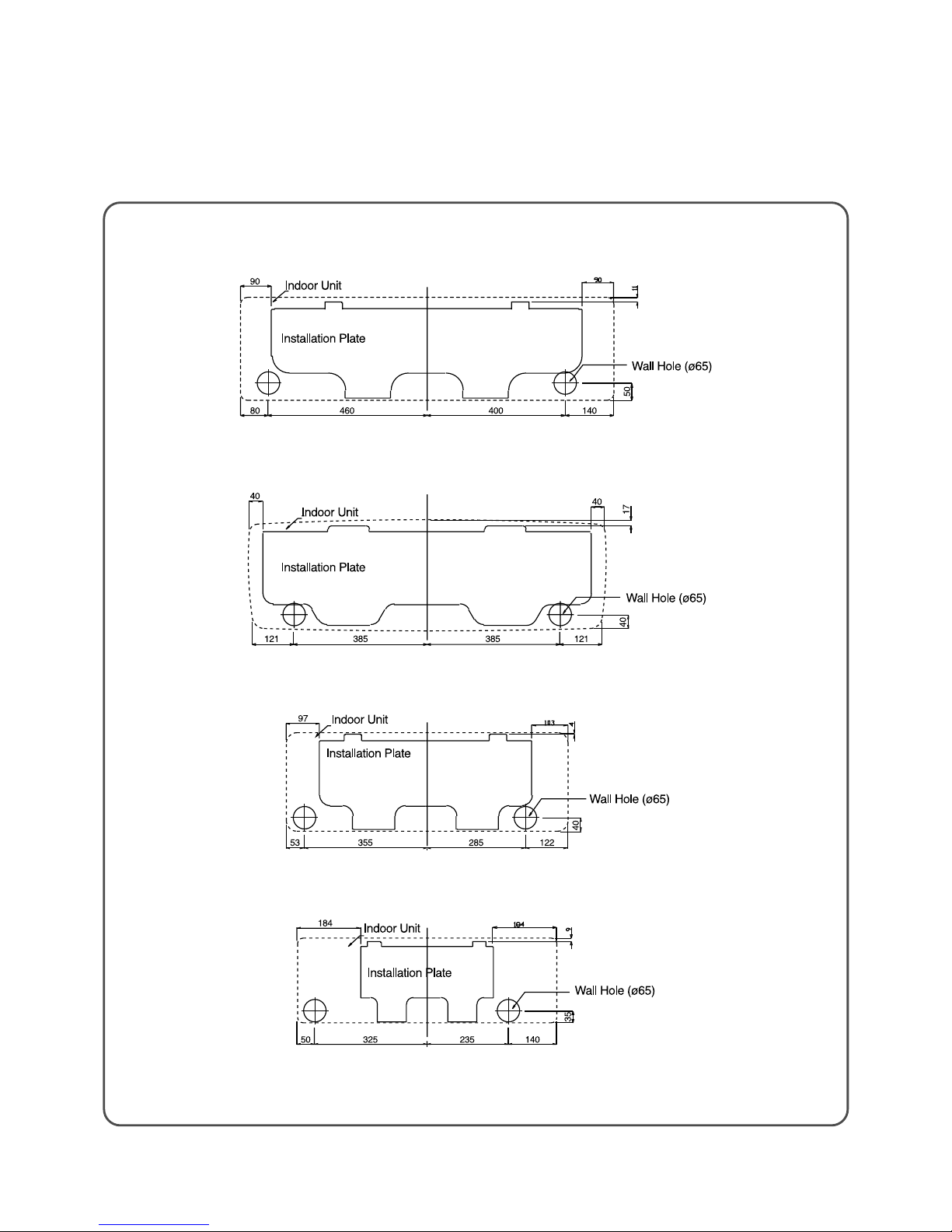
◆INSTALLING THE INSTALLATION PLA TE
Unit : mm
• DSA-245L, 245P
• DSA-185L, 185P
• DSA-125L, 125P
• DSA-095L
11
2
OUTDOOR UNIT
◆DSA-095L
Outlet
Foot Cushion
Cabinet Front
Cabinet Side
Panel T op
Guide Support
SVC Cover
Servise Valve
Inlet
Outlet
Inlet
256
286
324
539
549
460
654
12
◆DSA-125L, 125P, 185L, 185P
Inlet
Outlet
Outlet
Foot Cushion
Cabinet Front
Cabinet Side Panel Top Guide Support
SVC Cover
Servise Valve
580
800
320
360
400
589
615
Inlet

13
◆DSA-245L, 245P
Inlet
325
350
380
673
697
Outlet
Outlet
Foot Cushion
Cabinet Front
Cabinet Side
Panel T op
Guide Support
SVC Cover
Servise Valve
Inlet
549
872
14
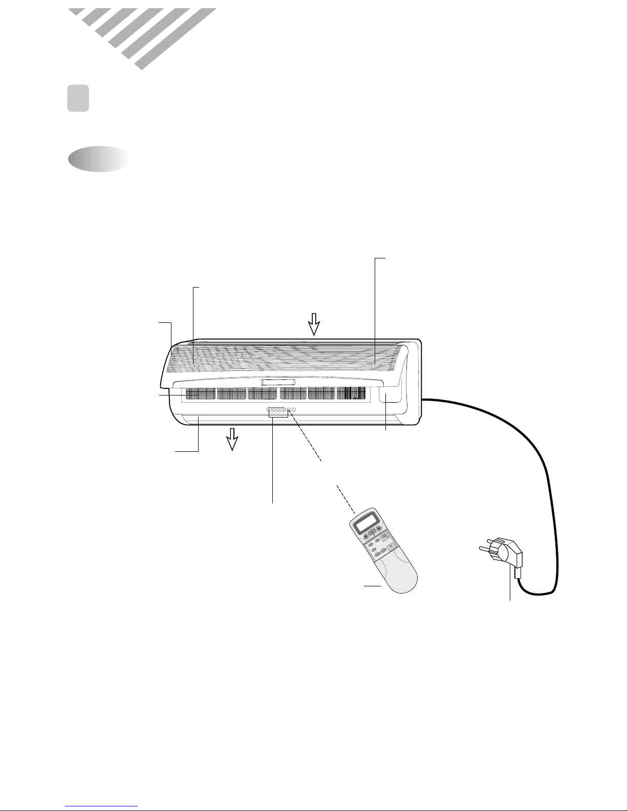
1
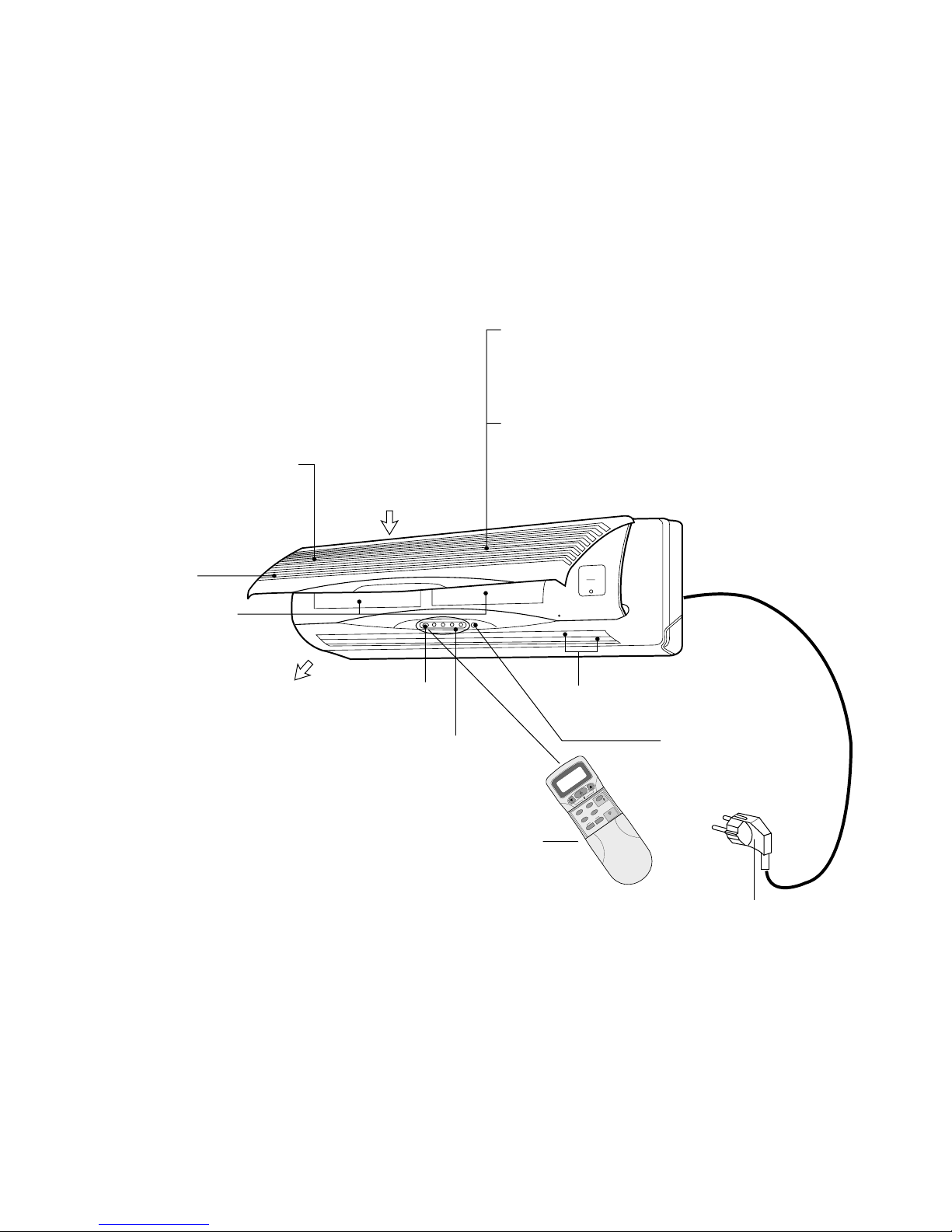
NAME AND FUNCTION OF PARTS
Indoor Unit
3. OPERATION
◆DSA-095L
Fan Direction
(Up/Down)
Connection Cover
Remove cover to access
the AC connection from
this unit to the outdoor unit.
O
N
O
F
F
E
N
T
E
R
C
A
N
C
E
L
T
I
M
E
R
R
E
S
E
T
F
A
N
D
I
R
.
F
A
N
S
P
E
E
D
M
O
D
E
S
L
E
E
P
O
N
/
O
F
F
T
E
M
P
.
Electrostatic Filter
Removes dust
particles from the air.
Indicators
Indicate the setting
Indoor Cover
Power Plug
Remote
Sensor
LCD Remote Controller
Deodorizing Filter
Removes bad smells
from the air.
Cold Air
Air In
Air Cleaning Filters
Removes dust and
prohibits germs.
M
O
D
E
S
L
E
E
P
O
N
/
O
F
F
T
I
M
E
R
E
N
T
E
R
/
C
A
N
C
E
L
F
A
N
S
P
E
E
D
T
U
R
B
O
/
M
I
L
D
F
A
N
D
I
R
.
15
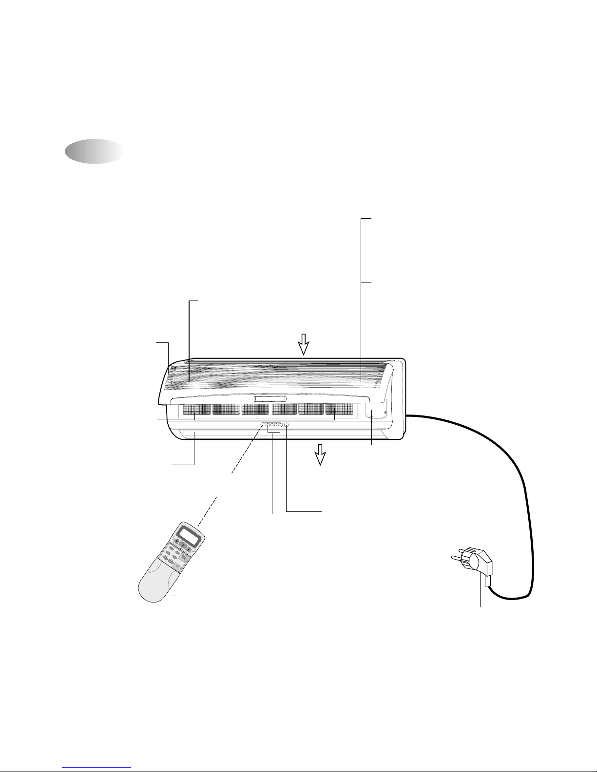
Indoor Unit
◆DSA-125L, 125P
Removes small dust and
generates (-) ions.
(DSA-125P)
Electrostatic Filter
Removes dust particles
from the air
(DSA-125L)
Electric Dust Collector
(Air clean Plasma)
Air Cleaning Filters
Removes dust and
prohibits germs.
Emergency/Remote
Switch
Slide to select the
desired position.
Indicators
Indicate the setting
Deodorizing Filter
Removes bad smells
from the air.
Fan Direction
(Up/Down)
Indoor Cover
Power Plug
Cold Air
Air In
O
N
O
F
F
E
N
T
E
R
C
A
N
C
E
L
T
I
M
E
R
R
E
S
E
T
F
A
N
D
I
R
.
F
A
N
S
P
E
E
D
M
O
D
E
S
L
E
E
P
O
N
/
O
F
F
T
E
M
P
.
LCD Remote Controller
Connection Cover
Remove cover to access
the AC connection from
this unit to the outdoor unit.
Remote
Sensor
MODE
SLEEP
ON/OFF
TIMER
ENTER/
CANCEL
FAN SPEED
VAPS
TURBO/MILD
FAN DIR.
OCON
16
Indoor Unit
◆ DSA-185L, 185P
Indoor Cover
Deodorizing Filter
Removes bad smells
from the air.
Test/Emergency/
Remote Switch
Slide to select
the desired position.
Indicators
Indicate the
AC setting.
Remote Sensor
Power PlugLCD Remote Controller
Air Cleaning
Filters
Removes dust
and prohibits
germs.
Cold Air
Air In
Fan Direction
(Up/Down)
ON
OFF
ENTERCANCEL
TIMER
RESET
FAN DIR.
FAN SPEED
MODE
SLEEP
ON/OFF
TEMP.
Removes small dust and
generates (-) ions.
(DSA-185P)
Electrostatic Filter
Removes dust particles
from the air
(DSA-185L)
Electric Dust Collector
(Air clean Plasma)
MODE
SLEEP
ON/OFF
TIMER
ENTER/
CANCEL
FAN SPEED
VAPS
TURBO/MILD
FAN DIR.
17
Indoor Cover
Deodorizing Filter
Removes bad
smells from the air.
Emergency/
Remote Switch
Indicators
Indicate the
AC setting.
Remote
Sensor
Power Plug
LCD Remote
Controller
Air Cleaning Filters
Removes dust and
prohibits germs.
AIR OUT
AIR IN
Fan Direction
(Up/Down)
M
O
D
E
S
L
E
E
P
O
N
/
O
F
F
T
I
M
E
R
E
N
T
E
R
/
C
A
N
C
E
L
F
A
N
S
P
E
E
D
T
U
R
B
O
/
M
I
L
D
F
A
N
D
I
R
.
Removes small dust and
generates (-) ions.
(DSA-245P)
Electrostatic Filter
Removes dust particles
from the air
(DSA-245L)
Electric Dust Collector
(Air clean Plasma)
◆ DSA-245L, 245P
MODE
SLEEP
ON/OFF
TIMER
ENTER/
CANCEL
FAN SPEED
VAPS
TURBO/MILD
FAN DIR.
OCON
18
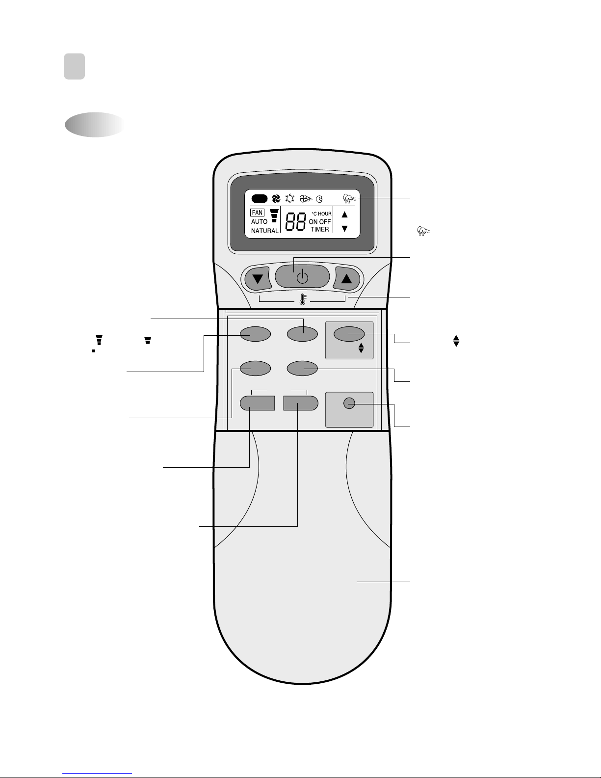
Name of Each Button
2
REMOTE CONTROLLER
MODE
SLEEP PLASMA
ON/OFF
TIMER
ENTER/
CANCEL
FAN SPEED
TURBO/MILD
Display
Displays information
pertaining to unit.
( DSA-125P, 185P, 245P)
TURBO/MILD
Press to be colder the unit.
PLASMA Buttons
Press to clean the polluted air.
(DSA-125P, 185P, 245P)
TIMER ENTER/CANCEL Button
Press to enter a timer setting or
to cancel timer setting
TIMER ON/OFF Button
Press to set the unit of or on time.
(0.5, 1, 1.5, 2, 2.5, 3, 4, 5, 6, 8,
10, 12, 16, 20, 24hr)
MODE Button
Press to cycle through the modes
(Auto/Quick/Cool/Fan/Dehumidifier)
SLEEP Button
Press to set the unit for
the sleep mode.
FAN DIR. Button
Press to select up/down
direction for fan.
ON/OFF Button
Press to turn the unit
on or off.
TEMPERATURE Buttons
Press to raise or lower
the desired temperature.
FAN SPEED Button
Press to select the fan speed
(High " ", Middle " ",
Low " ").
COVER
Slide down to access most
of the remote buttons.
Slide down further to
access the battery
compartment.
AUTO
FAN DIR.
19
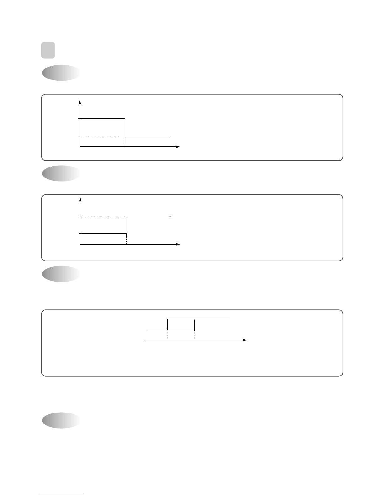
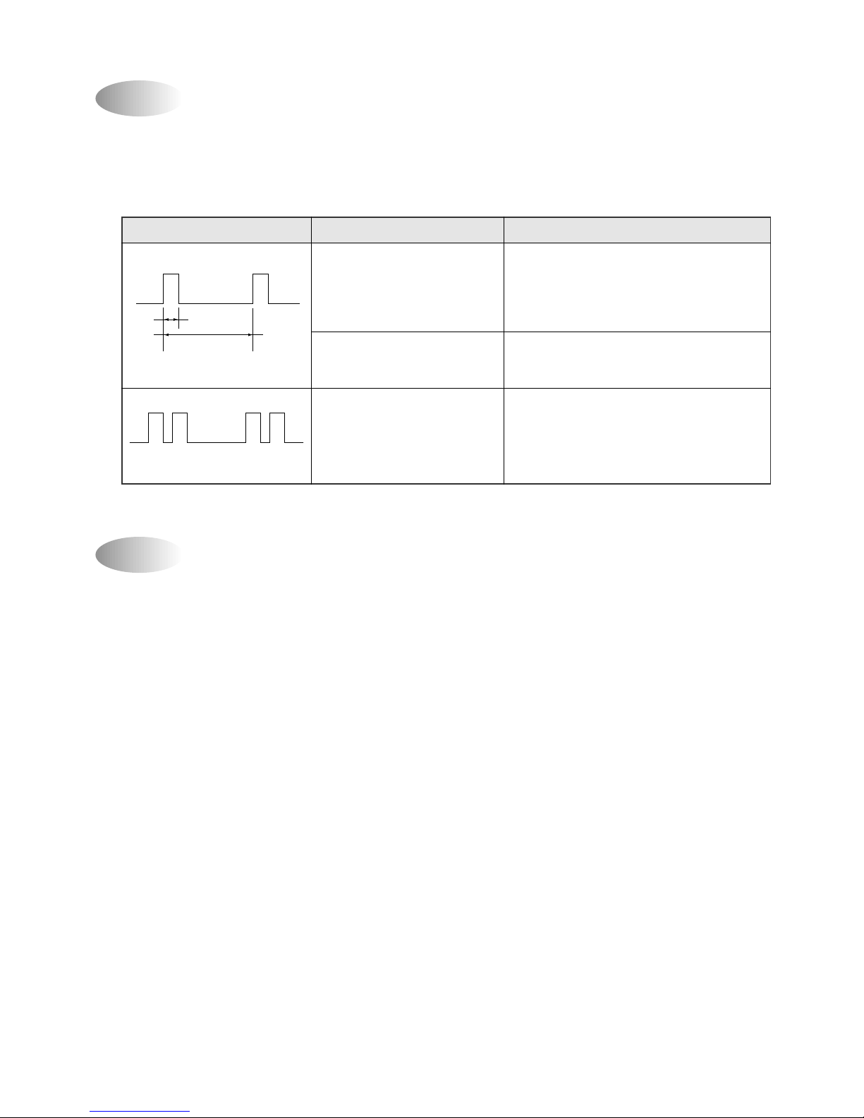
If you set time in OFF-Timer Mode, the unit will stop at the set time.
If you set time in ON-Timer Mode, the unit will run at the set time.
(1) Range of setting temperature: 18~32°C
(2) Setting temperature: Operating temperature of compressor
(3) During the time of test operating, Fan (Indoor, Outdoor) and Compressor is running regardless of room
temperature.
If the Indoor Unit Display receive the signal of Remote Controller, you can hear the signal "beep –" or "beep,
beep".
(1) In the case of receiving ON/OFF signal-"beep" "beep"
(2) And so on-"beep"
OFF-Timer
3
DESCRIPTION OF FUNCTIONS
Unit ON
Unit OFF
SET Time
HOUR
ON
OFF
ON-Timer
Unit ON
Unit OFF
SET Time
HOUR
ON
OFF
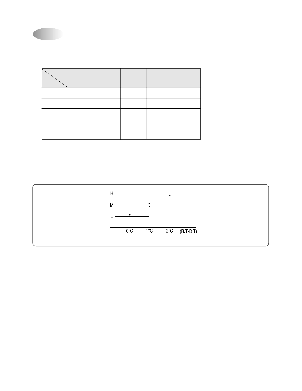
Control of Room Temperature
Buzzer
COMP (ON)
*RT: ROOM TEMPERATURE
DT: DESIRED TEMPERATURE
COMP (OFF)
-1°C0°C
(COOLING)
(RT-DT)
+1°C
20
Fan Speed (Indoor Unit)
(1) Motor speed (high speed, normal speed, low speed).
(2) Remote controller setting fan speed. (Auto, L, M, H, Natural)
(3) Relation of operating mode between fan speed. (legned: X-no relation)
(4) Automatic Operation
If the unit is set in 'AUTO' mode, the unit operates automatically according to the room temperature to keep the
room temperature comfortable.
(COOLING)
FAN ONLY COOL
DEHUMI-
AUTO QUICK
DIFICATION
H HHLHH
M MMLMH
L LLLLH
Auto Auto L Auto H
Natural Natural Natural L Natural H
21
(1) When the remote controller is lost, damaged or the battery is discharged, the Emergency operation can be
used to run the unit.
(2) The setting conditions of Emergency operation are as follows.
• Operation mode: Quick
• Preset temperature:18°C
• Fan speed: High
* Y ou cannot operate with remote controller.
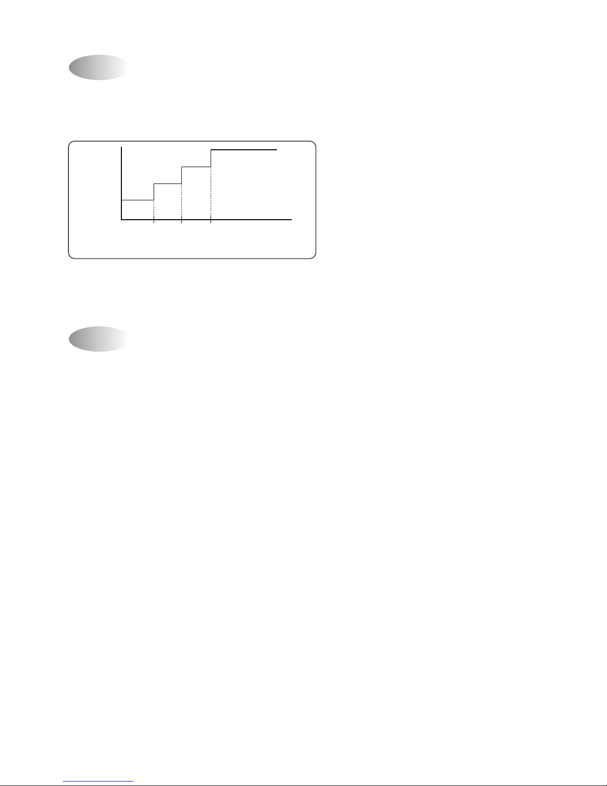
(1) When you are going to sleep, select sleep switch and the unit controls the room to the desired temperature.
(The unit will not operate after 4 hour)
(2) For changing the temperature.
(3) To cancel sleep mode, press the SLEEP button again or press the MODE button once.: the SLEEP
indicator will disappear in the display.
Sleep Mode
Emergency Operation
0 0.5 1.0 HOUR
(COOLING CYCLE)
DT
+0.5°C
+0.5°C
+0.5°C
22
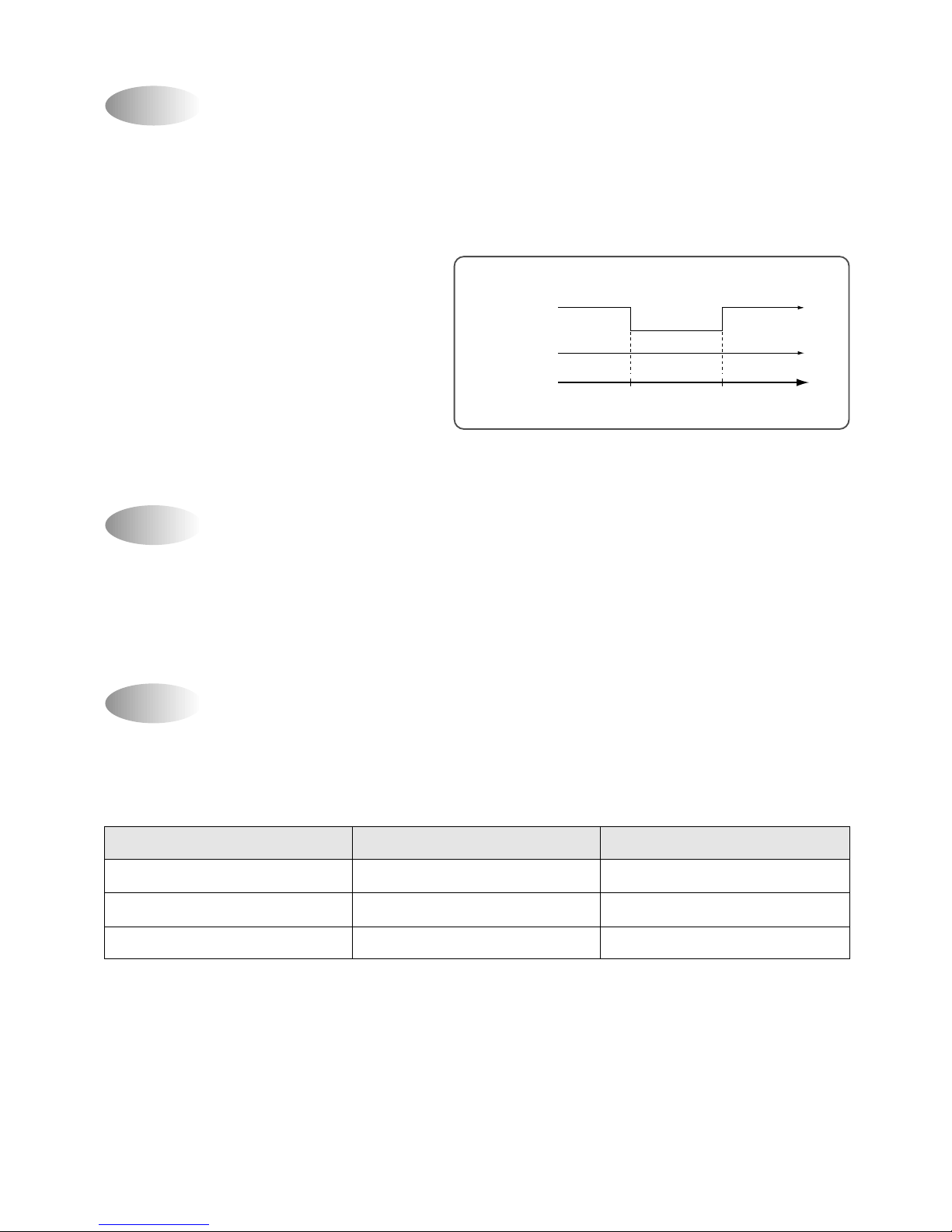
Frost Prevention of Indoor Unit
When the unit operates at low ambient temperature, frost may appear on the Evaporator. When the indoor coil
temperature is lower than 0°C at the end of 10 minutes of continuous compressor operation from the start, the
microcomputer of the unit stops the compressor to protect the unit from the frost. The control procedure for
indoor coil freeze protection.
1) The compressor and outdoor fan turn off.
2) Indoor fan operates according to user set speed.
3) The normal operation returns when the indoor coil
temperature is higher than 7°C or equal to 7°C.
-1°C+7°C
Compressor and
Outdoor Fan
ON ON
OFF
Indoor Fan
Set speed
(Indoor coil temperature)
Auto Mode
(1) In Auto Mode
After the indoor fan is operated for 20 seconds in the Auto Mode the unit will operate automatically by selecting
operating Mode according to the room temperature
(2) Selecting Operating Mode Again
Room temperature meets desired temperature and the compressor stops running over 30 minutes, then the unit
selects operating Mode again.
3 min. Time Delay of Compressor
In normal operation, there is a time delay of three minutes between turn off and turning back on including initial
power up.
ROOM TEMPERA TURE
DT-2°C RT
DT-2°C
≤
RT ≤DT+3°C
DT+3°C RT
OPERA TING MODE
Cooling
Dehumidifier
Cooling
FLAP POSITION
Cooling Position
Cooling Position
Cooling Position
(RT: Room temperature)
>
<
23
1) Cooling Mode
1Fan Speed: Super high speed
2Air discharge direction: Fixed
3Set temperature: 18°C (Fixed)
4Compressor and Outdoor Fan
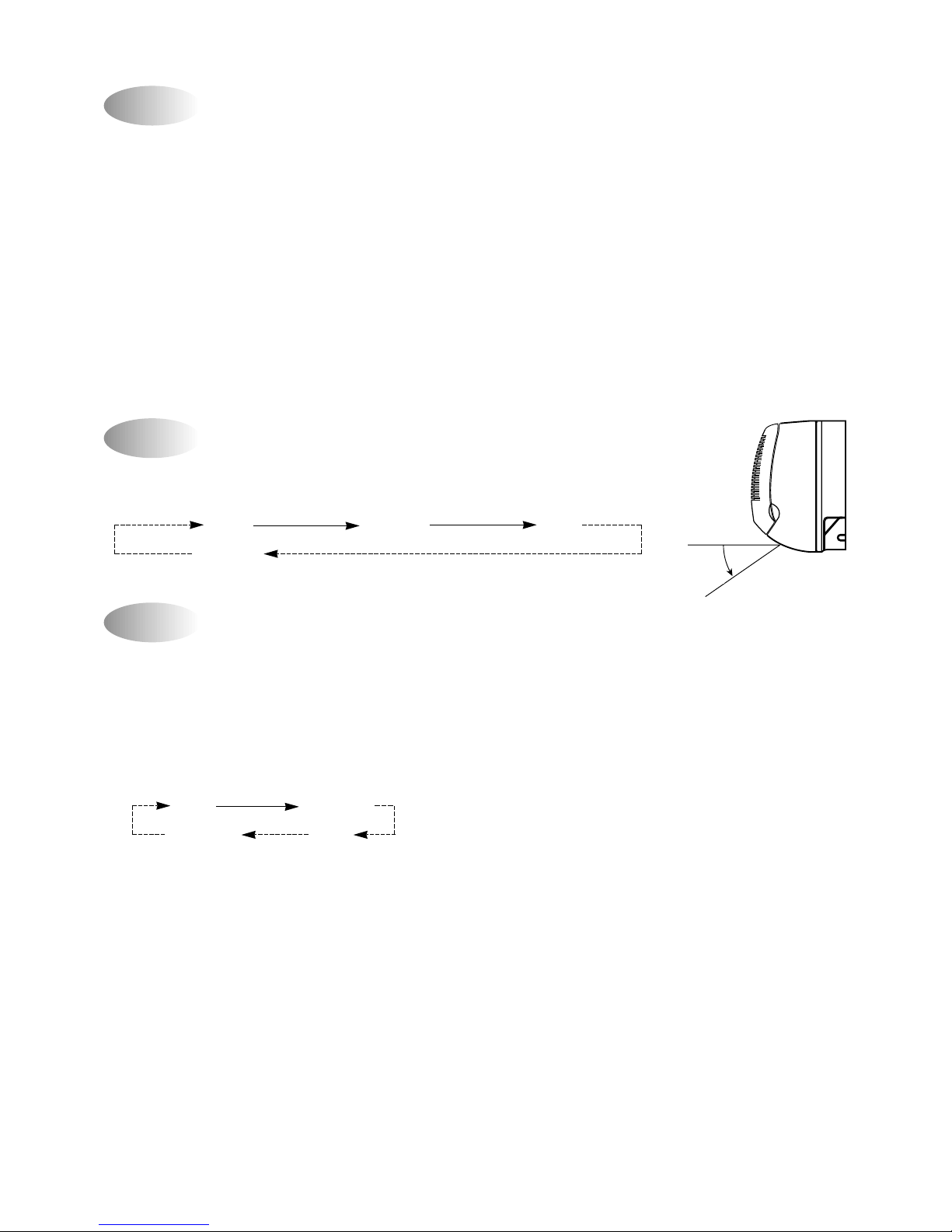
The air discharge direction procedure is below
Fixed Up/Down
Up/Down Fixed
Dehumidification Mode
Air Discharge Direction(only remocon operation)
Quick Mode(Powerful Cooling)
The air discharge direction procedure is below.
Fixed Up/Down Fixed
Up/Down
1Desired temperature < Room temperature
Outdoor Fan, Compressor : ON
Indoor Fan : Low speed
2Desired temperature ≥Room temperature
Compressor : 3 min/ON, 5 min/OFF
Fan Speed : low speed
3Room temperature ≤18°C
Compressor : OFF
Fan speed : Low speed
COOLING POSITION
24
Self-Diagnostic Function
The control will contain diagnostic test to verify the integrity of the system.
(1)Error Code Display Pattern
1 ON LAMP: Blink
Self Diagnostic Function Description
1. Sensor Error
Open or Short circuit of Sensors (Room and Indoor Coil Sensor)
Open : Micom, Input Voltage 0~0.3V, Short: Micom, Input V oltage 4.7~5.0V
2. Compressor Error
At the start operation, the Compressor is ON and 5 Minutes later, the Temperature change value of Indoor
Coil is below +/-2°C.
• Emergency Mode Operation detect only
LED BLINK PATTERN CASE NOTE
Room Sensor open or Short • Continuously working to fix room
temperature 18°C in cooling mode.
• I/D coil sensor open or short Do not working
1 times blink
• Compressor or electrical parts Continuously working
of compressor error.
2 times blink
• Gas leak
0.5s
8s
25
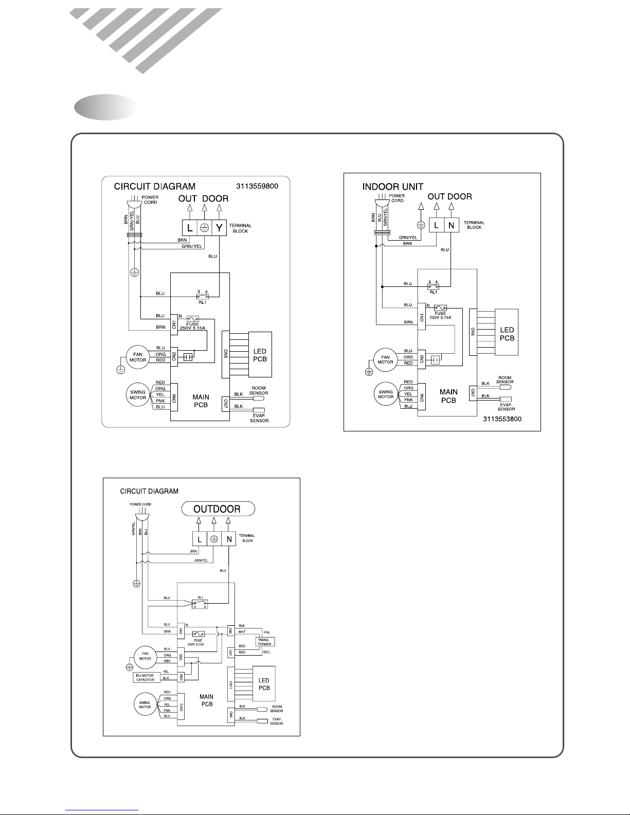
4. WIRING DIAGRAM
Indoor Unit
◆ DSA-095L ◆ DSA-125L
◆ DSA-185L, 245L
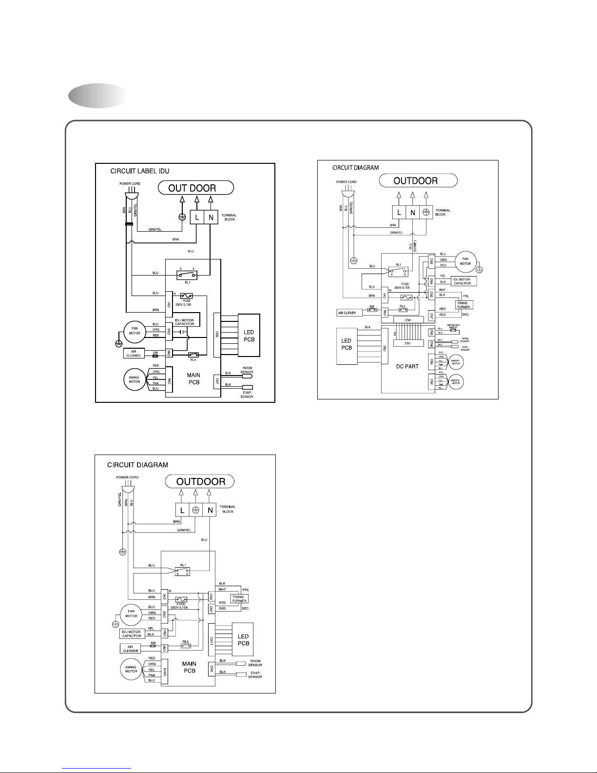
26
Indoor Unit
◆ DSA-125P ◆ DSA-185P
◆ DSA-245P
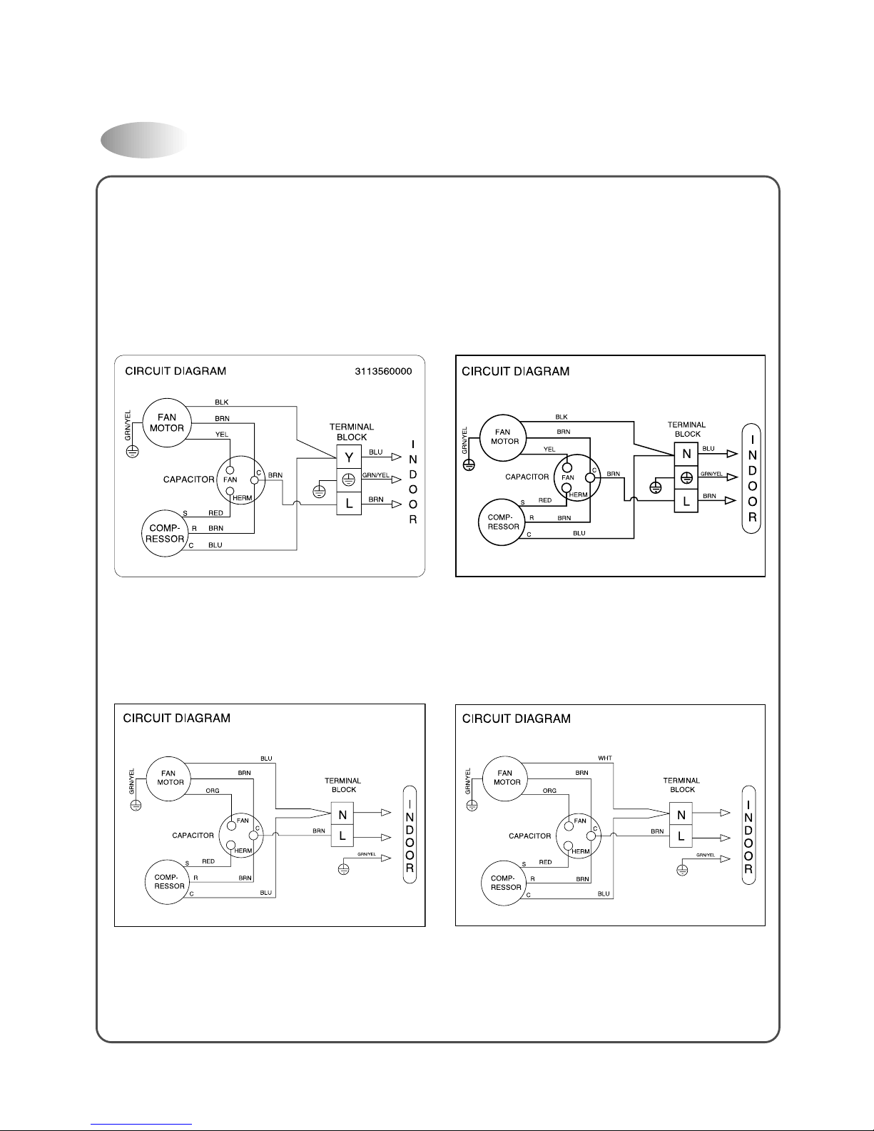
27
Outdoor Unit
◆ DSA-095L ◆ DSA-125L, 125P
◆ DSA-185L, 185P ◆ DSA-245L, 245P
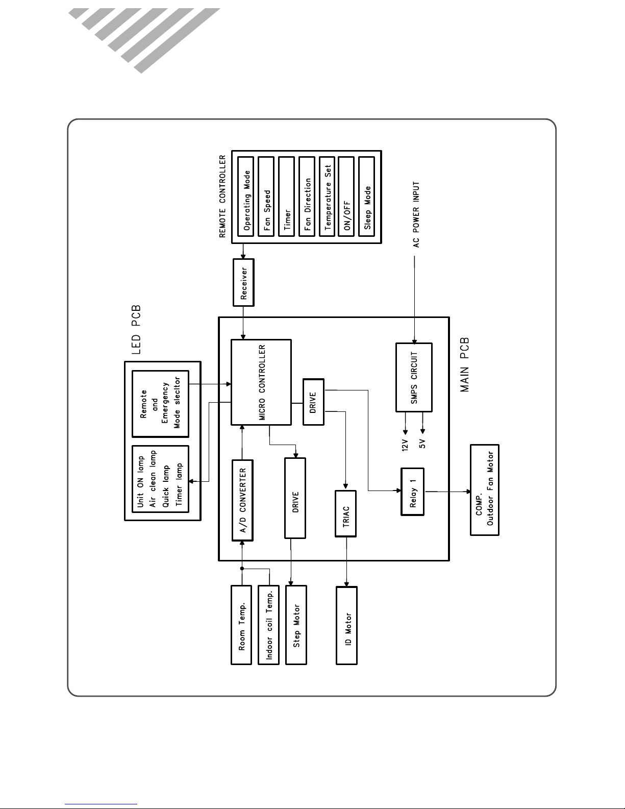
28
5. CONTROL BLOCK DIAGRAM
◆DSA-095L, DSA-125L, 125P
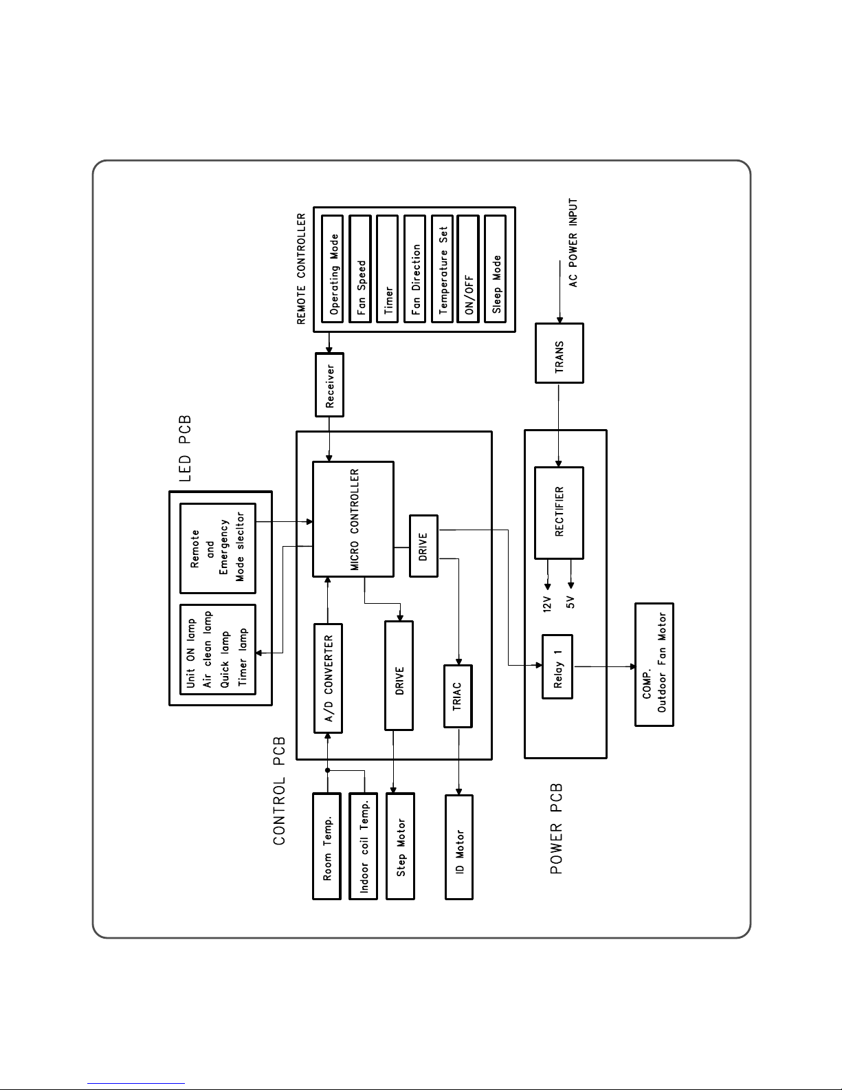
◆DSA-185L, 185P
29
 Loading...