

Daewoo DSA-100L, DSA-120L Service Manual

Service Manual
Split System Air
Conditioner
Model: DSB-090L/DSB-120L
DSA-100L/DSA-120L
DAEWOO ELECTRONICS CO., LTD.
CONTENTS
1. Specifications................................................................................................2
2. Outline and Dimensions .................................................................................4
3. Operation.....................................................................................................6
4. Wiring Diagram..........................................................................................18
5. Refrigerant Cycle.........................................................................................21
6. Control Block Diagram.................................................................................22
7. Electric Circuit Diagram................................................................................23
8. Trouble Shooting..........................................................................................25
9. Key Components of Electronic Circuit............................................................47
10. Disassembly Instructions ...............................................................................50
1) Indoor Unit..............................................................................................50
2) Outdoor Unit...........................................................................................51
3) Exploded Diagram (Indoor Unit) ...............................................................52
4) Exploded Diagram (Outdoor Unit) ............................................................55
5) Control Box Assembly..............................................................................60
Contents
2
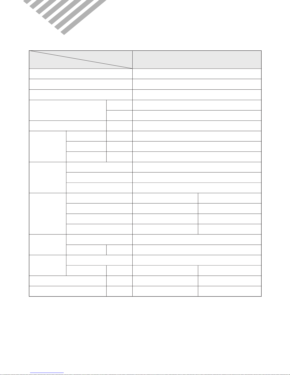
1. SPECIFICATIONS
MODEL
DSB-090L
ITEM
Function Cooling
Class T
Power AC 220-240V / 50Hz
Capacity W 2,770
Btu/h 9,500
Dehumidification l/h 2.1
Running Current A 4.5A
Power Input W 950W
Starting Current A 24A
Type Rotary
Model RCB 090A001
Capacitor 25µF/400VAC
Division Indoor Unit Outdoor Unit
Type Cross flow fan Propeller fan
Capacitor 1.0µ F 400VAC 1.8µF 400VAC
Motor Model Number IC-8428DWKG7A IC-9630DWLC5A
Control Capillary
Charge Q'ty g 1,170
Type Flare
OD
(Liquid/Suction)
in(mm) 1/4 (6.35) 1/2 (12.7)
Dimensions (W x H x D) mm 925 x 285 x 194 666 x 552 x 264
Net Weight kg 9.7 34
Electrical
Data
Compressor
Fan
Refrigerant
(R-22)
Connection
¡ DSB-090L

3
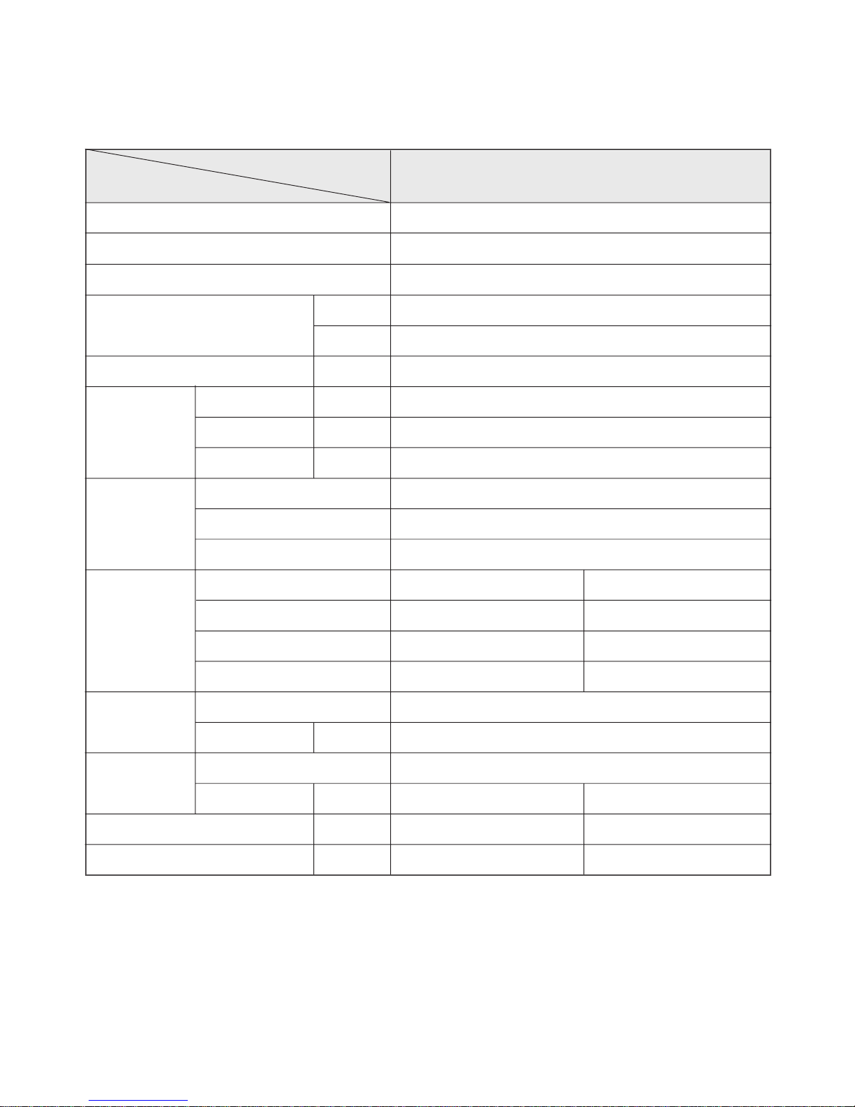
MODEL
DSB-120L
ITEM
Function Cooling
Class T
Power AC 220-240V / 50Hz
Capacity W 3,507
Btu/h 12,000
Dehumidification l/h 2.1
Running Current A 5.7A
Power Input W 1,250A
Starting Current A 34A
Type Rotary
Model RCB 120A001
Capacitor 25µF / 400VAC
Division Indoor Unit Outdoor Unit
Type Cross flow fan Propeller fan
Capacitor 1.0µ F 400VAC 3.5µF 400VAC
Motor Model Number IC-8428DWKG7A IC-9430DWLC5A
Control Capillary
Charge Q'ty g 1,300
Type Flare
OD
(Liquid/Suction)
in(mm) 1/4 (6.35) 1/2 (12.7)
Dimensions (W x H x D) mm 925 x 285 x 194 666 x 552 x 264
Net Weight kg 9.7 34
Electrical
Data
Compressor
Fan
Refrigerant
(R-22)
Connection
¡ DSB-120L
4
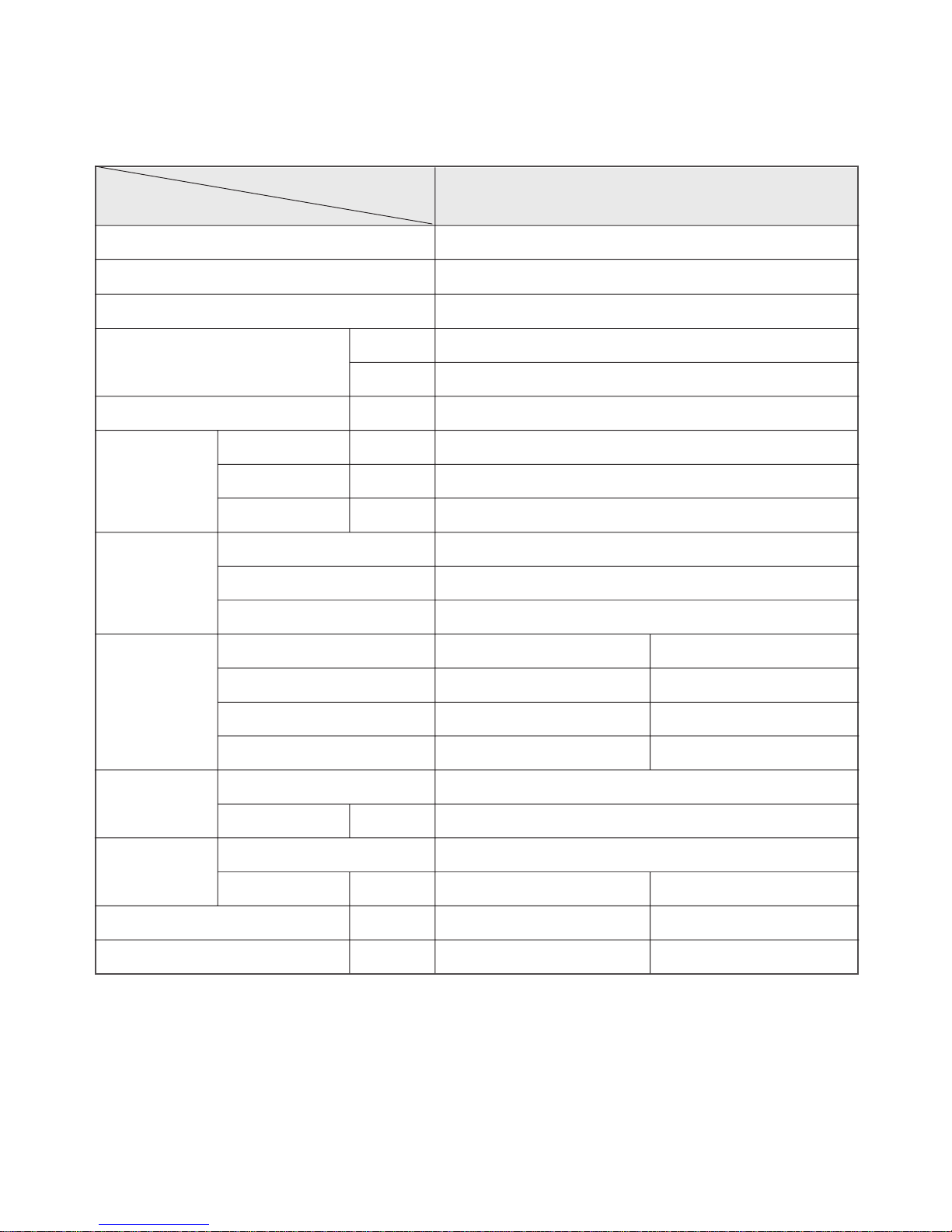
MODEL
DSA-100L
ITEM
Function Cooling
Class T
Power AC 208-230V / 60Hz
Capacity W 2,923
Btu/h 10,000
Dehumidification l/h 2.1
Running Current A 5.1A
Power Input W 1,115W
Starting Current A 27A
Type Rotary
Model RCA 100A001
Capacitor 25µF/400VAC
Division Indoor Unit Outdoor Unit
Type Cross flow fan Propeller fan
Capacitor 1.0µ F 400VAC 1.8µF 400VAC
Motor Model Number IC-8428DWKG7A IC-9630DWLA6A
Control Capillary
Charge Q'ty g 1,150
Type Flare
OD
(Liquid/Suction)
in(mm) 1/4 (6.35) 1/2 (12.7)
Dimensions (W x H x D) mm 925 x 285 x 194 666 x 552 x 264
Net Weight kg 9.7 34
Electrical
Data
Compressor
Fan
Refrigerant
(R-22)
Connection
¡ DSA-100L
5
MODEL
DSA-120L
ITEM
Function Cooling
Class T
Power AC 208-230V / 60Hz
Capacity W 3,507
Btu/h 12,000
Dehumidification l/h 2.1
Running Current A 5.7A
Power Input W 1,250W
Starting Current A 34A
Type Rotary
Model RCA 120A001
Capacitor 30µF / 400VAC
Division Indoor Unit Outdoor Unit
Type Cross flow fan Propeller fan
Capacitor 1.0µ F 400VAC 2.0µF 400VAC
Motor Model Number IC-8428DWKG7A IC-9630DWLA6A
Control Capillary
Charge Q'ty g 1,200
Type Flare
OD
(Liquid/Suction)
in(mm) 1/4 (6.35) 1/2 (12.7)
Dimensions (W x H x D) mm 925 x 285 x 194 666 x 552 x 264
Net Weight kg 9.7 34
Electrical
Data
Compressor
Fan
Refrigerant
(R-22)
Connection
¡ DSA-120L
6
REMOCON
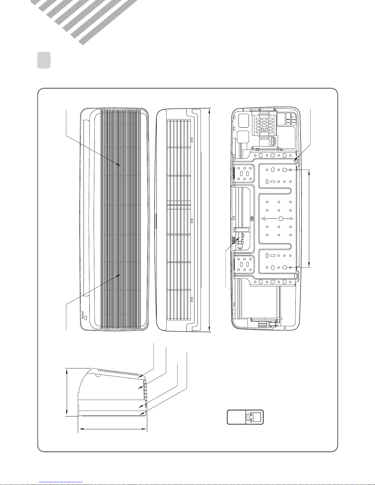
Filter - L Filter - R
Grille Insert
Frame Grille
Body
Plate Mounting
Connecting Pipe
Plate Mounting
406
194
285
925
2. OUTLINE AND DIMENSIONS
1
INDOOR UNIT
¡ DSB-090L/DSB-120L/DSA-100L/DSA-120L
7
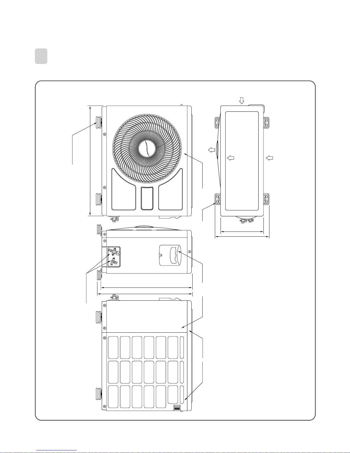
2
OUTDOOR UNIT
Cabinet SideHandleCabinet Front Foot
264
334
Panel Top
Cabinet Back
552
572
Inlet
AIR
Inlet
Outlet
Foot Cushion
Service Valve
666
¡ DSB-090L/DSB-120L/DSA-100L/DSA-12OL
8
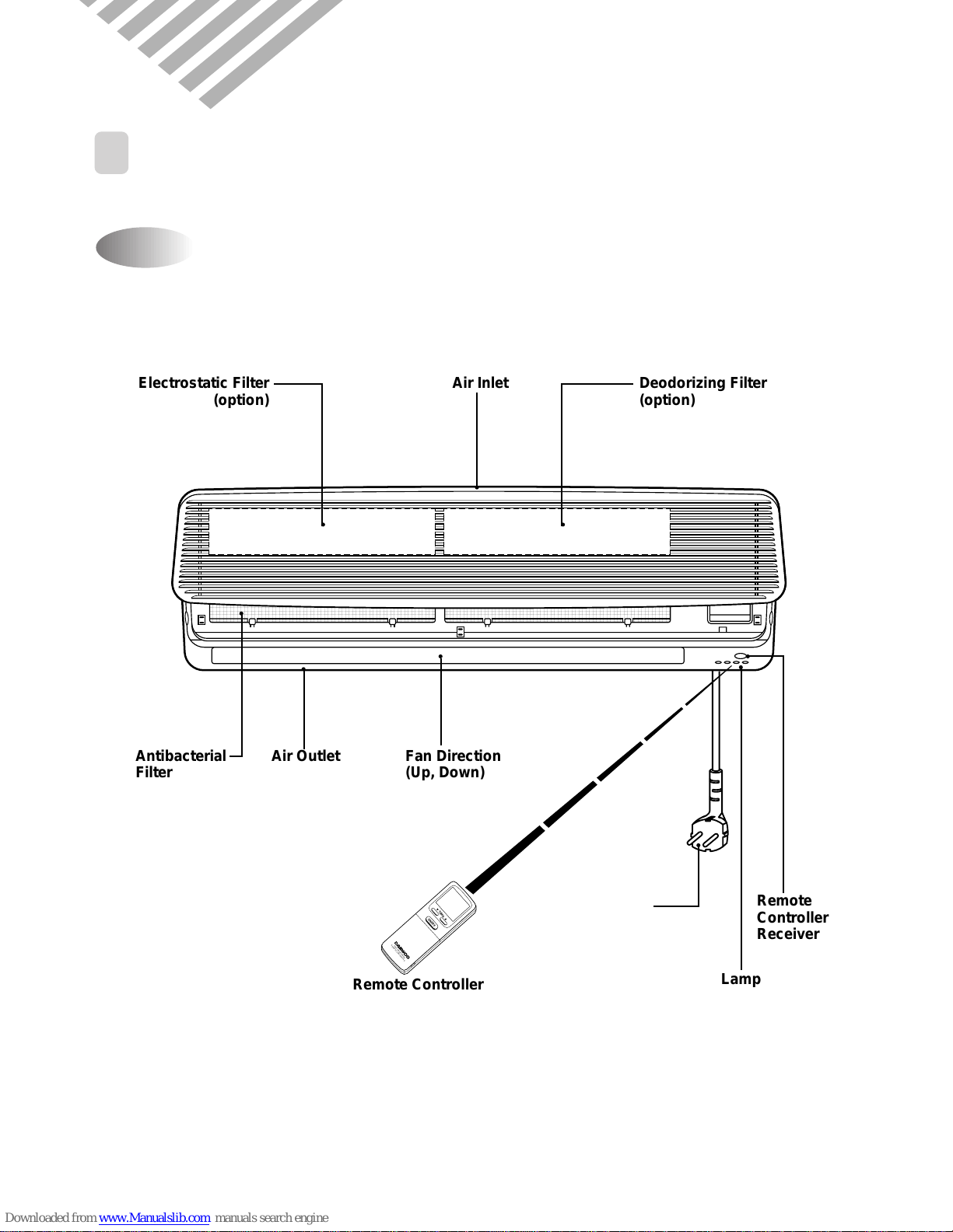
1
PARTS OF NAME AND FUNCTION
Indoor Unit
3. OPERATION
¡ DSB-090L/DSB-120L/DSA-100L/DSA-120L
Power Plug
ON/OFF
TEMP.
AIR-CONDITIONER
REMOTE CONTROLLER
Electrostatic Filter
(option)
Deodorizing Filter
(option)
Air Inlet
Antibacterial
Filter
Air Outlet Fan Direction
(Up, Down)
Remote Controller
Remote
Controller
Receiver
Lamp
9
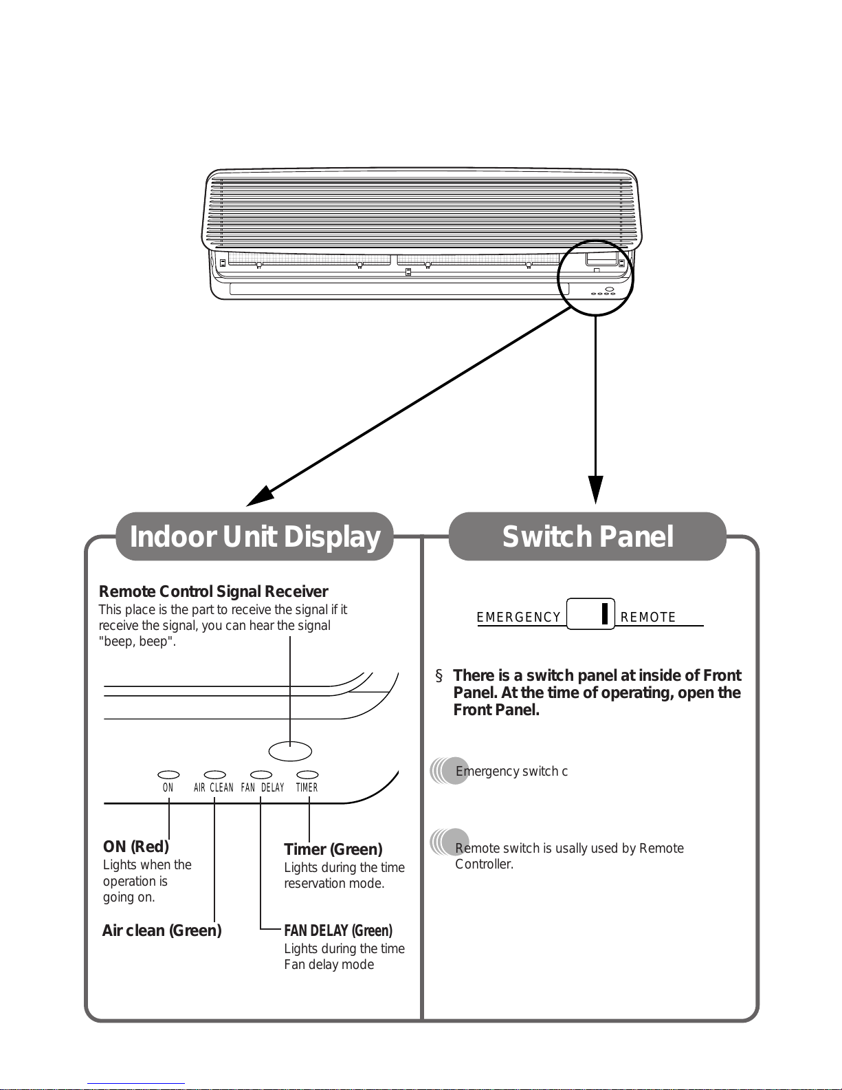
Remote Control Signal Receiver
This place is the part to receive the signal if it
receive the signal, you can hear the signal
"beep, beep".
Timer (Green)
Lights during the time
reservation mode.
ON (Red)
Lights when the
operation is
going on.
§ There is a switch panel at inside of Front
Panel. At the time of operating, open the
Front Panel.
Air clean (Green)
FAN DELAY (Green)
Lights during the time
Fan delay mode
Indoor Unit Display Switch Panel
EMERGENCY REMOTE
ON AIR CLEAN FAN DELAY TIMER
Remote switch is usally used by Remote
Controller.
Emergency switch can be used when the remote
controller is lost or testing.
¡ DSB-090L/DSB-120L/DSA-100L/DSA-120L
10
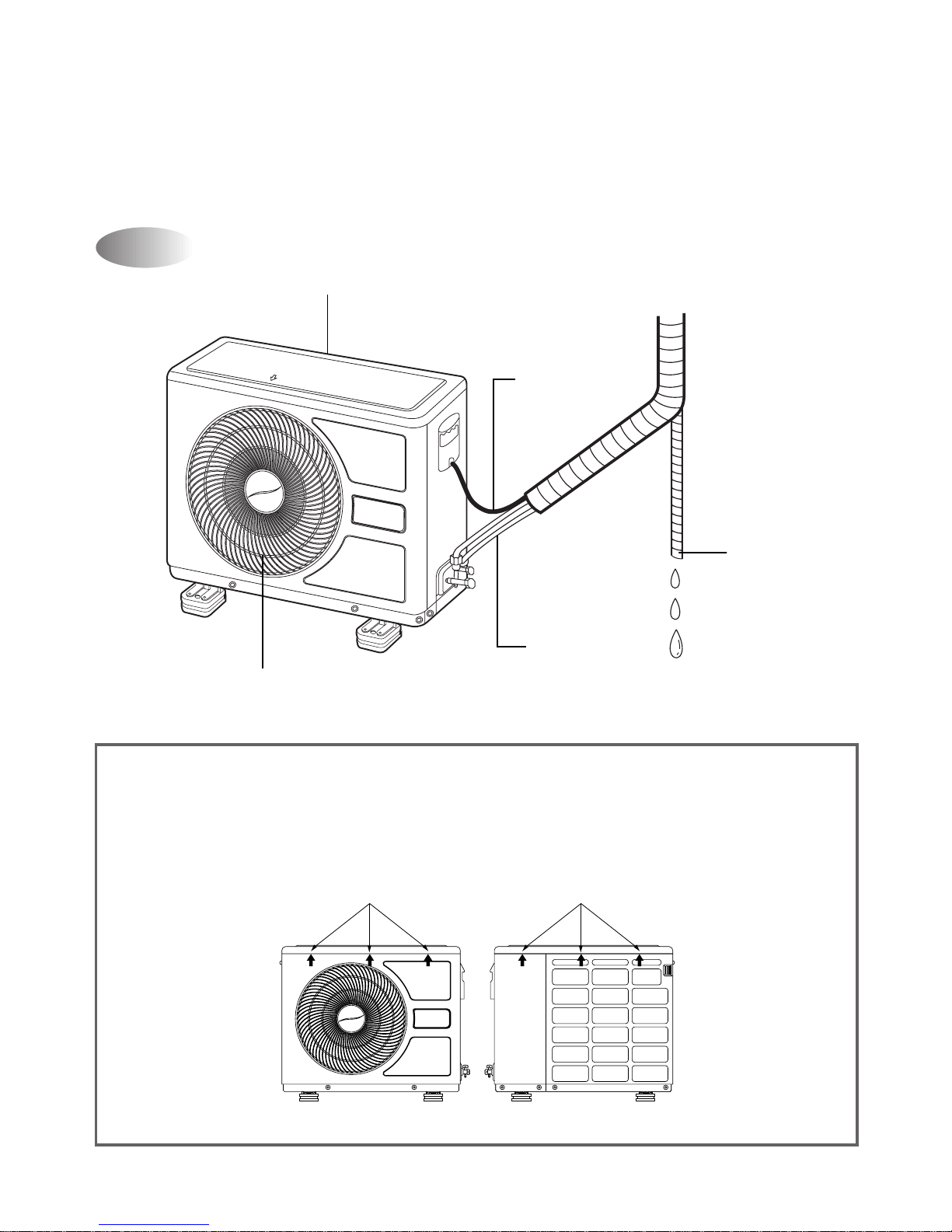
AIR
Air Inlet (side Back)
Air Outlet
Connection
Wire
Connecting
Pipe
Drain Hose
Outdoor Unit
¡ DSB-090L/DSB-120L/DSA-100L/DSA-120L
NOTE:
How to remove Top Panel
1. Loosen the screw at left and right side.
2. Push the three parts op Front and Back sides like figure orderly.
3. Unhook the locking parts of Top Panel.
The front locking parts
FRONT SIDE BACK SIDE
The back locking parts
11
LMH
TEMP.
ON/OFF
FAN DIR. MODE
FAN SPEED
ON OFF ENTER
CANCEL
SLEEP
TIMER
RESET
TEMP.
A
SLEEP
TIMER
AUTO
NATURAL
HOUR
OFFON
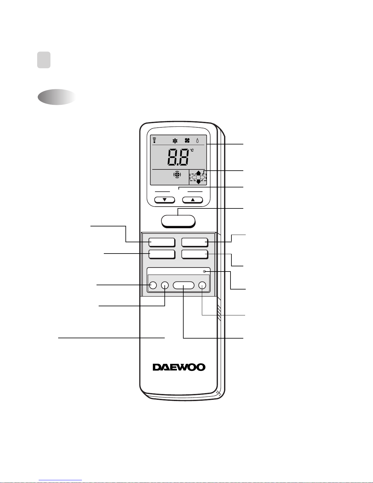
AIR CONDITIONER
REMOTE CONTROLLER
Display
Displays information pertaining to the
unit.
The option is LEFT/RIGHT direction.
Temperature Buttons
Press to raise or lower the desired
temperature.
MODE Button
Press to cycle through the modes
(Auto/Cool/Fan/Dehumidifier).
RESET Button
Press to reset settings to their default
positions.
CANCEL Button
Press to cancel Timer settings.
SLEEP Button
Press to set the unit for the sleep mode.
ON/OFF Button
Press to turn the unit on or off.
ENTER Button
Press to enter a Timer setting.
FAN DIR. Button
Press to select the fan
direction.
FAN SPEED Button
Press to select the fan speed
(Auto, L, M, H or Natural).
TIMER ON Button
Press to set the on time.
TIMER OFF Button
Press to set the off time.
Cover
Slide down to access most
of the remote buttons.
Slide down further to
access the battery
compartment.
Name of Each Button
2
REMOTE CONTROLLER
¡ DSB-090L/DSB-120L/DSA-100L/DSA-120L

12
LMH
TEMP.
A
SLEEP
TIMER
AUTO
NATURAL
HOUR
OFFON
Replacing Batteries
3
REMOTE CONTROLLER DISPLAY
Open the cover after
pressing the arrow
direction and pulling out.
Put the drycell by §]§^
direction.
Close the cover after
pushing into arrow
direction.
MODE Indicators (Auto/Cool/Fan/Dehumidifier)
Lights to indicate the mode selected.
TRANSMITTER Icon
Lights to indicate
a signal is being sent.
TEMP. Indicator
Lights to indicate the
temperature is being set.
SLEEP Indicator
Lights to indicate the
unit is in sleep mode.
NA TURAL Indicator
Lights to indicate the
temperature is being set.
Temperature
Indicator
Lights to indicate the
temperature
TIMER Indicators
Lights to indicate the timer
function modes.
FAN DIRECTION
Indicators
Lights to indicate the fan
direction.
The option LEFT/RIGHT
dirction
FAN Indicators
Lights to indicate
the fan speed.
1
2
3
ON/OFF
TEMP.
ON/OFF
TEMP.
¡ DSB-090L/DSB-120L/DSA-100L/DSA-120L
13
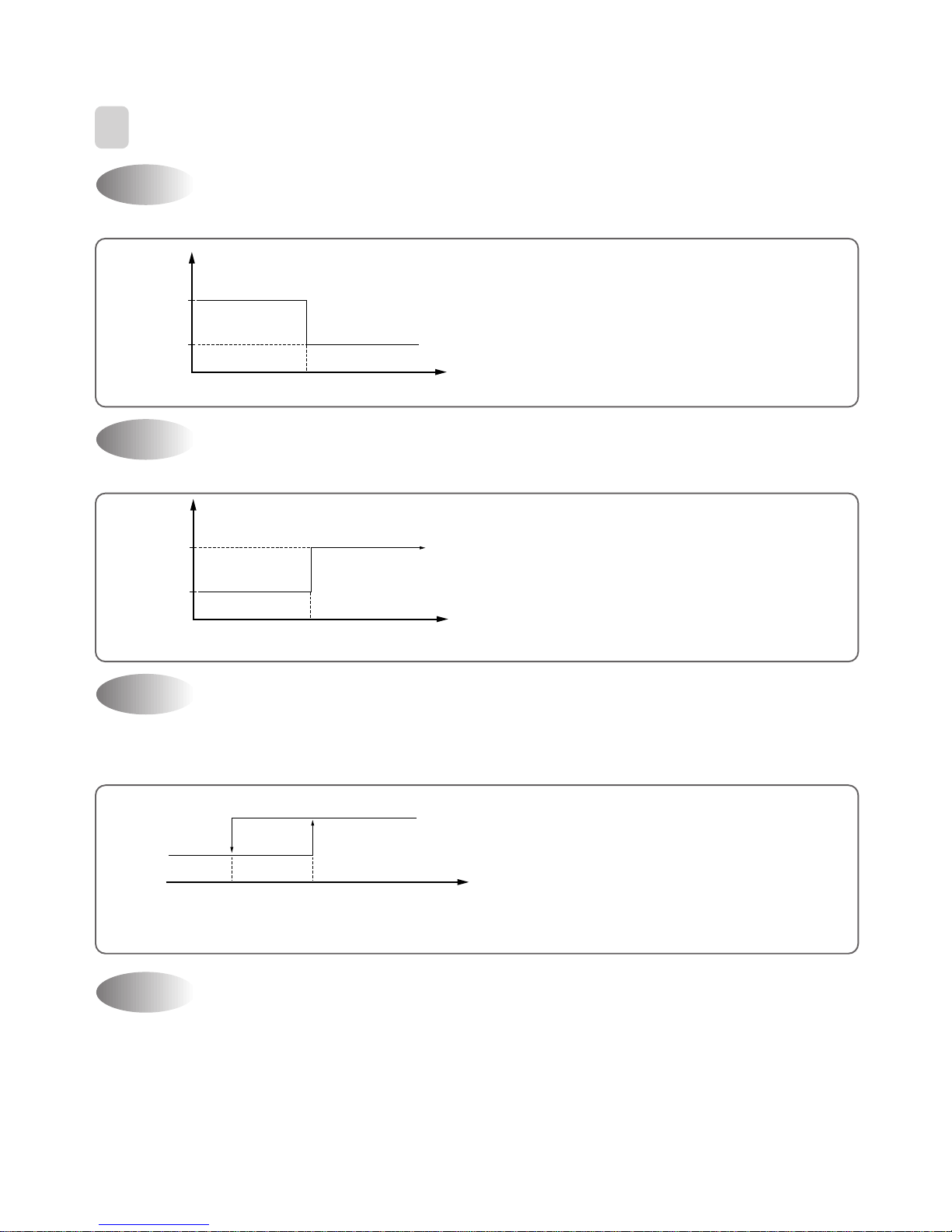
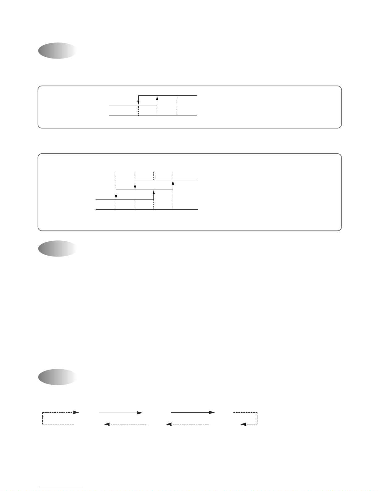
If you set time in OFF-Timer Mode, the unit will stop at the set time.
If you set time in ON-Timer Mode, the unit will run at the set time.
(1) Range of setting temperature: 18~32°C
(2) Setting temperature: Operating temperature of compressor
If the Indoor Unit Display receive the signal of Remote Controller, you can hear the signal "beep –" or "beep,
beep".
(1) In the case of receiving ON/OFF signal-"beep""beep"
(2) And so on-"beep"
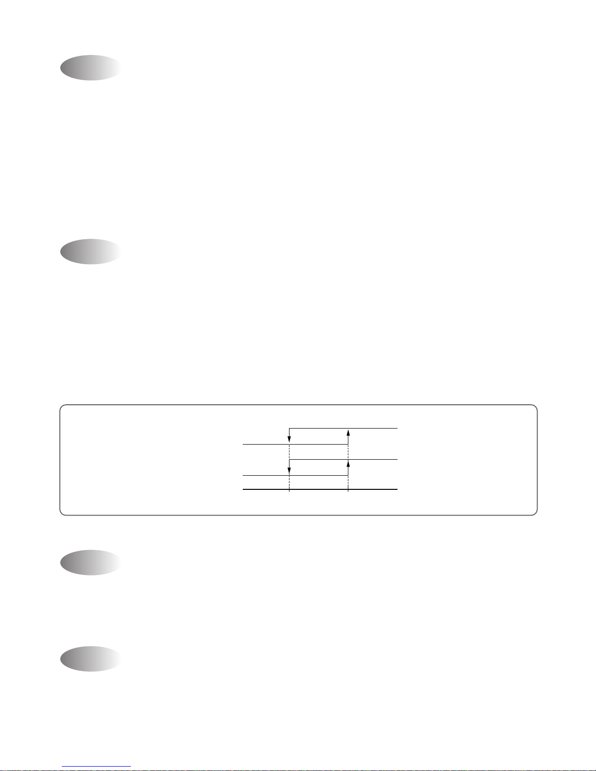
OFF-Timer
4
DESCRIPTION OF FUNCTIONS
Unit ON
Unit OFF
SET Time
HOUR
ON
OFF
ON-Timer
Unit ON
Unit OFF
SET Time
HOUR
ON
OFF
Control of Room Temperature
Buzzer
COMP (ON)
(COOLING)
Desired temperature
COMP (OFF)
-1˚C
Temperature
¡ Room temperatrue
< setting temperature
Compressor OFF
Room temperature
> setting temperafure
Compressor ON
(
(
14
(1) When you are going to sleep, select sleep switch and the unit controls the r oom to the desir ed temperature.
(The unit will not operate after 4 hour)
(2) For changing the temperature.
Sleep Mode
0 0.5 1.0 HOUR
SET TIME
Desired
Difference
desired temperature
between room
temperature (°C)
0.5°C
0.5°C
0.5°C
Temperature
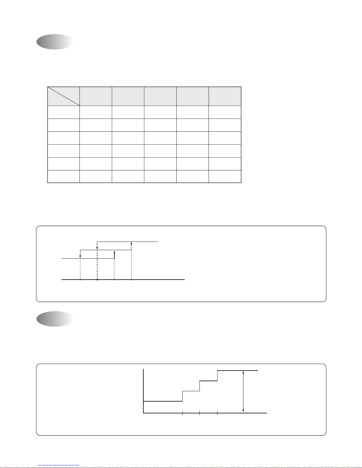
Fan Speed (Indoor Unit)
(1) Motor speed (Super high speed, high speed, normal speed, low speed, ultra low speed).
(2) Remote controller setting fan speed. (Auto, L, M, H, Natural)
(3) Relation of operating mode between fan speed.
(4) Automatic Operation
If the unit is set in 'AUTO' mode, the unit operates automatically according to the room temperature to keep
the room temperature comfortable.
FAN ONLY COOL
DEHUMI-
AUTO AUTO II
DIFICATION
Super high XXXXSuper high
H HHXHX
MMMXMX
LLLXLX
Auto X Auto Auto Auto X
Natural Natural Natural X Natural X
0
L
M
H
+1°C+2°C+3°C (R.T-D.T)
(D.T)
(COOLING)
R.T=Room temperafure
D.T=Desired temperafure
15
(1) When the remote controller is lost, damaged or the battery is discharged, the Emergency operation can be
used to run the unit.
(2) The setting conditions of Emergency operation are as follows.
• Operation mode: AUTO
• Preset temperature: 26°C
• Discharge Air Direction: SWING (up and down)
• Fan speed: AUTO
¡Y ou cannot operate with remote contr oller.
Emergency Operation
Frost Prevention of Indoor Unit
When the unit operates at low ambient temperature, frost may appear on the Evaporator. When the indoor coil
temperature is lower than 0°C at the end of 10 minutes of continuous compressor operation from the start, the
microcomputer of the unit stops the compressor to protect the unit from the frost. The contr ol procedur e for
indoor coil freeze protection.
1) The compressor and outdoor fan turn off.
2) Indoor fan operates according to user set speed.
3) The normal operation returns when the indoor coil temperature is higher than 7°C or equal to 7°C.
0°C7°C
Compressor and
Outdoor Fan
OFF
OFF
ON
Set Speed
Indoor Fan
(Indoor coil temperature)
3 min. Time Delay of Compressor
In normal operation, there is a time delay of three minutes between turn off and turning back on including initial
power up.
When indoor fan motor is on, it always starts at normal speed and then it operates desired speed.
Indoor Fan Motor Starting
16
Dehumidification Mode
Air Discharge Direction(only remocon operation)
The air discharge direction procedur e is below.
Fixed Up/Down Fixed
Up/Down Fixed Left/Right
Auto Mode I
(1) When the room temperature is higher than 28 ºC (Cooling Mode)
! Compressor and lndoor Fan
@ The fan will automatically operate as following Figure
-1 0 1
°C
OFF
ON
(Room temperature Desired temperature)
H
M
L
0+1+2+3
°C
(Room temerature Desired temperature)
!Desired temperature < Room temperature
Outdoor Fan, Compressor : ON
Indoor Fan : Low speed
@ Desired temperature ¡ˆRoom temperature
Compressor : 3 min/ON, 5 min/OFF
Indoor Fan : 3 min 30 second/ON, 4 min 30 second/OFF
Fan Speed : Ultra low speed
# Room temperature ¡´18°C
Compressor : OFF
Indoor Fan : 1 min/ON, 7 min/OFF
17
!Fan Speed: Super high speed
@ Air dischar ge direction: Fixed
# Set temperature: 18°C (Fixed)
$ Compr essor and Outdoor Fan
The air discharge direction procedur e is below
Fixed Up/Down Fixed
Up/Down Fixed Left/Right
ƒRThe option is LEFT/RIGHT direction.
Auto Mode II(Powerful Cooling)
-1
OFF
ON
(Room temperature-18˚C)
01
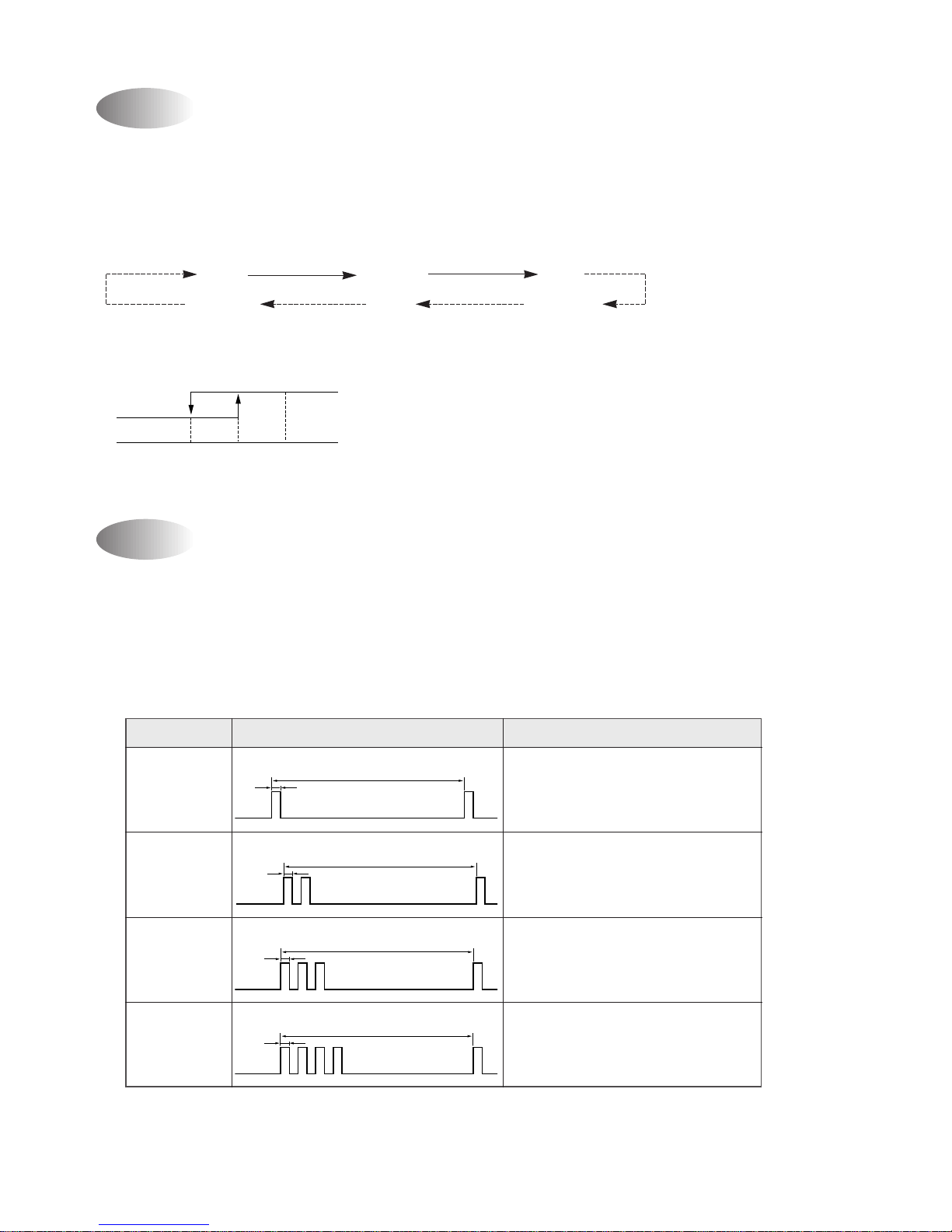
Self-Diagnostic Function
The control will contain diagnostic test to verify the integrity of the system.
(1) Error Code Display Pattern
!ON LAMP: ON (Red) LED ON/OFF
@ Error Code
ERROR CODE
DIDSPLAY PATTEN ERROR CONTENTS
1 Romm air thermistor, connector
2 Indoor coil thermistor, connector
3
Compressor, Electrical parts of
comp. Gas leak
4
Motor, Conector, P.C.B.
8 seconds
0.5 second
8 seconds
0.5 second
0.5
second
8 seconds
0.5 second
8 seconds
0.5 second
18
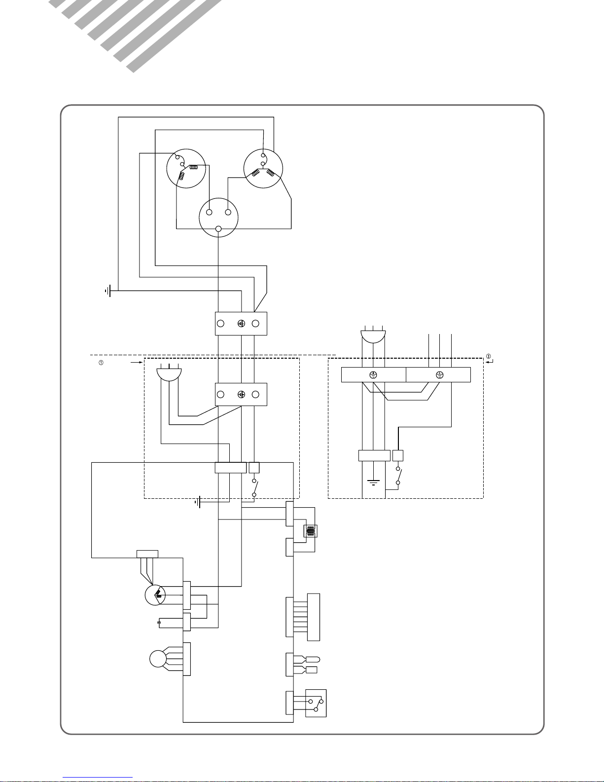
4. WIRING DIAGRAM
¡ DSB-090L/DSB-120L/DSA-100L/DSA-120L
FAN MOTOR
BRN
H
S
CAPACITOR
YEL
COMPRESSOR
RED
BRN
FAN
HERM
C
BRN
BLK
BLU
YELLOW/GREEN
R
C
R
OUTDOOR
TERMINAL
BLOCK
BLU
YELLOW/GREEN
BROWN
INDOOR
TERMINAL
BLOCK
BLU
YEL/GRN
BRN
BLU
BRN
YEL/GRN
BLU
POWER CORD
PCB TRANS
LED PCB
1
1
2
3
COMP
1 2 1 2 123456 7 1 23 4 12 3
BLK
BLK
LED
LED
BLU
RED
GRN
YEL
GRY
BRN
BLK
BLK
BLK
BLK
BLK
YEL
RED
BLU
I/D SENSOR
SELECT S/W
HOLE
SENSOR
123
ORG
GRY
YEL
R
S
C
12 3
èXée
FAN MOTOR
FAN MOTOR
CAPACITOR
SWING
MOTOR
12 12345
BLU
ORG
RED
BLK
YEL
RED
PINK
BLU
ORG
YEL
OUTDOOR UNIT INDOOR UNIT
Y
L
Y
L
1
1
2
3
COMP.
RELAY
N Y
POWER CORD
BRN
YEL/GRN
BLU
BLU
BRN
YEL/GRN
BLU
DOMESTIC
EXPORT
L1L
 Loading...