

Daewoo DQ-K2121N-P Service Manual

S/M No. :VKB2121NN0
Service Manual
COMBO
TIMELAPSE VCR
Model : DQ-K2121N-P
✔ Caution :
In this Manual, some parts can be changed for improving, their
performance without notice in the parts list. So, if you need the latest
parts information,please refer to PPL(Parts Price List) in Service
Information Center (http://svc.dwe.co.kr).
DAEWOO ELECTRONICS Corp.
July. 2003
http : //svc.dwe.co.kr

1
SAFETY&PRECAUTIONS........................................................................................................................................2
FEATURES & SPECIFICATION................................................................................................................................4
EXTERNAL VIEWS...................................................................................................................................................8
FRONT VIEWS .......................................................................................................................................................................................8
BACK VIEWS ..........................................................................................................................................................................................9
REMOCON ............................................................................................................................................................................................10
ALIGNMENT INSTRUCTIONS................................................................................................................................11
ELECTRICAL ADJUSTMENT.................................................................................................................................12
CIRCUIT OPERATION............................................................................................................................................16
CIRCUIT INFORMATION........................................................................................................................................22
CONNECTION DIAGRAM(DQ-K2121N(D)-P).......................................................................................................................................22
POWER SCHEMATIC DIAGRAM(DQ-K2121N(D)-P) ...........................................................................................................................23
RECODER A/V SCHEMATIC DIAGRAM(DQ-K2121N(D)-P)................................................................................................................24
SERVO/SYSCON SCHEMATIC DIAGRAM(DQ-K2121N(D)-P)............................................................................................................25
FBT/CRT SCJE,ATOC DIAGRAM(DQ-K2121N(D)-P) ..........................................................................................................................26
LOGIC SCHEMATIC DIAGRAM(DQ-K2121N(D)-P) .............................................................................................................................27
JACK/AUDIO SW SCHEMATIC DIAGRAM(DQ-K2121N(D)-P) ............................................................................................................28
MULTIPLEXER SCHEMATIC DIAGRAM(DQ-K2121N(D)-P)................................................................................................................29
MONITOR A/V DIAGRAM(DQ-K2121N(D)-P).......................................................................................................................................30
TROUBLESHOOTING FLOW CHART ...................................................................................................................31
VIDEO CIRCUIT ....................................................................................................................................................................................31
SERVO-SYSCON CIRCUIT...................................................................................................................................................................35
AUDIO CIRCUIT ....................................................................................................................................................................................43
POWER PART.......................................................................................................................................................................................46
MONITOR PART....................................................................................................................................................................................47
MUX PART.............................................................................................................................................................................................48
VCT 3834 PIN ASSIGN...........................................................................................................................................50
µ
-COM PORT DESCRIPTION ...............................................................................................................................52
COMPONENTS LOCATION GUIDE ON PCB BOTTOM VIEW..............................................................................54
DISASSEMBLY .......................................................................................................................................................58
ELECTRICAL PARTS LIST.....................................................................................................................................59
14 INCH & 20 INCH DIFFERENT PARTSLIST.............................................................................................................................................................76
CONTENTS
This table is unofficial and for reference only. Be sure to confirm the precise values for your particular
country and locality
2
SAFETY & PRECAUTIONS
SAFETY CHECK AFTER SERVING
Examine the area surrounding the repaired location for damage or deterioration. Observe that screw, parts and wires
have been returned to original positions. Afterwards, perform the following tests and conform the specified values in
order to verify compliance whit safety standards.
1. Insulation resistance test
Confirm the specified insulation resistance between power
cord plug prong and externally exposed parts of the set
(RF terminals, antenna terminals, video and audio input and
output terminals, microphone jacks, earphone jacks, etc.)
isgreater than values given in table 1 below.
2. Dielectric strengthen test
Confirm specified dielectric strengthen between power cord
plug prongs and exposed accessible parts of the set
(RF terminals, antenna terminals, video and audio input
output terminals, microphone jack, ear phone jacks, etc.)
is greater than values given table 1.
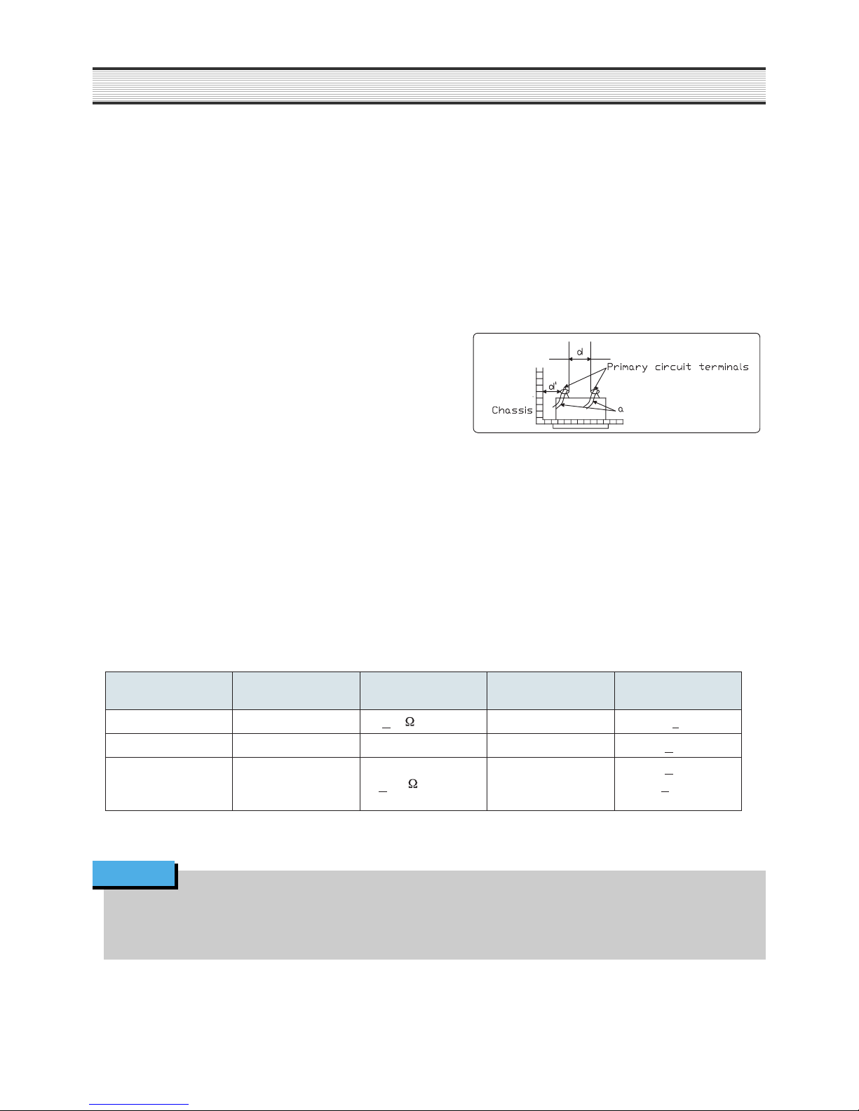
3. Clearance distance
When replacing primary circuit component, confirm specified clearance distance (d), (dÕ) between soldered
terminals, and between terminals and surrounding metallic parts. See table below.
NOTE
* : Class model only
AC Line Voltage Region
Insulation
Resistance
Dielectric
Strength
Clearance
Distance(d),(d’)
100V Japan
>1M /500V DC
1kV
AC 1min.
> 3
110 to 130V
USA & Canada
- 900V AC 1min.
> 3.2
* 110 to 130V
200 to 240V
Europe
Australia
Latin America
>10M /500V DC 4kV AC 1min.
> 6(d)
> 8(d’)
(a :Power cord)
Rating for selected areas
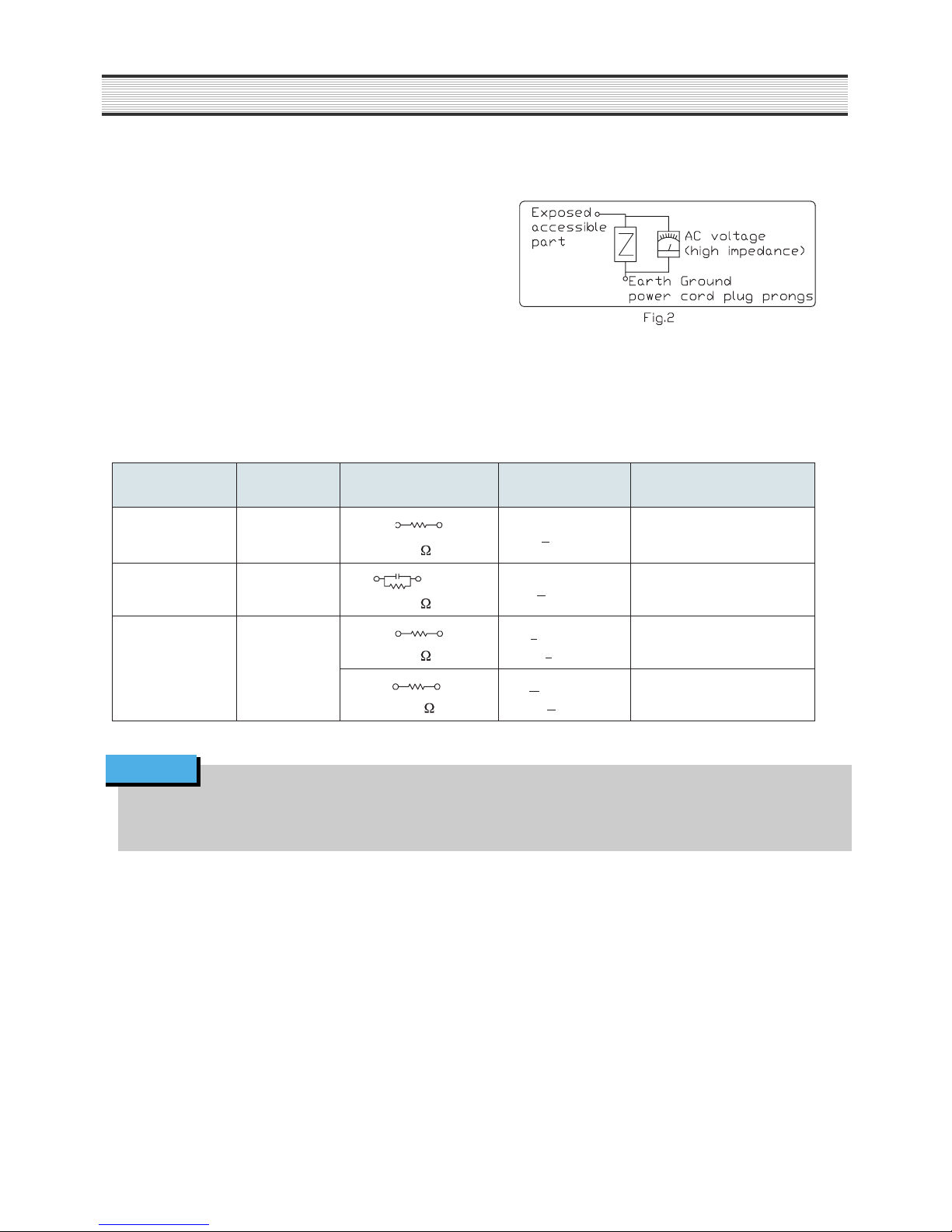
4. Leakage current test
Confirm specified or lower leakage current between B(earth
ground, power cord plug prongs) and externally exposed
accessi-ble parts (RF terminals, antenna terminals, video and
audio input output terminals, microphone jacks, earphone
jacks, etc.)
Measuring method:(Power ON) Insert load Z between B(earth
ground, power cord plug prongs) and exposed accessible
parts. Use on AC voltmeter to measure across both terminals
of load Z. See figure2 and following table.
3
SAFETY & PRECAUTIONS
This table is unofficial and for reference only. Be sure to confirm the precise values for your particular
country and locality.
NOTE
Rating for selected areas
AC Line Voltage Region Load Z
Leakage Cur-
rent( i )
Clearance Distance(d),(d’)
100V Japan
1k
i
<
1 mArms
Exposed accessible parts
110 to 130V USA &Canada
15k mF
1k
i
<
0.5mArms Exposed accessible parts
110 to 130V
200 to 240V
Europe
Australia
2k
i
<
0.7mA peak
i
<
2mAdc
Antenna earth terminals
50k
i
<
0.7mA peak
i <
1mAdc
Other terminals

4
FEATURES & SPECIFICATION
GENERAL
FEATURE NTSC SYSTEM REMARK
DESTINATION NTSC : NORTH AMERICA
COLOR SIGNAL NTSC : NTSC
EFFECTIVE PICTURE SIZE 14Ó -> HEIGHT : 8.27Ó(21cm), WIDTH : 11.00Ó(28cm)
20Ó -> HEIGHT : 13.27Ó(34Cm) , WIDTH : 17.09Ó(43Cm)
CALENDAR 2003~2102
OSD LANGUAGE ENGLISH Only
LETTER COLOR WHITE
BLUE BACK YES
SUPER IMPOSE DATA DISPLAY YES
OSD ON/OFF YES(DISPLAY KNOB)
MULTIPLE INPUT YES
SEQUENTIAL SWITCHER FOUR-POSITION COMPOSITE VDEO CHANNELS FROM 1 TO 4
POWER FAIL COMPENSATION ABOUT 30 DAY
REAL TIME RECORD NTSC : 30Hr
SET/REC LOCK YES(FRONT VIEW)
REMOCON YES
SAFETY REQULATION NTSC(UL, FCC)Ó
POWER REQUIREMENT AC 110V-240V~, 50/60HzÓ
POWER CONSUMPTION 75W
WEIGHT 14Kg
SET SIZE(WIDTH*HEIGHT*DEPTH)
14Ó : W387 * H403 * D373mm, 20Ó : W387 * H403 * D373mm
ACCESSORY REMOCON, INSTRUCTION BOOKS, WARRANTY CARD, AD STICKER
FEATURE NTSC SYSTEM REMARK
MENU 1. Monitor Mode Set
1) Clock Set(Example : To set the color to March 13,2003 at 13:50)
- Date Fromat : (MON/DAY/YR) Month/Day/Year or Day/Month/Year <First condition
:Month/Day/Year>
- 13:50:00 (HR/MIN/SEC) Time set<First condition :12:00:00>
- Thu 03/13/03 (MON/DAY/YR) Day of the Week, Month(or Day) /Day(or Month)/Year setÓ
<First condition :01/01/03>
2) Screen Display Set
- Alarm Time 01/02/03 . . . 60Sec/Off <First condition : 03Sec>
- Date/Time Yes or No <First condition : Yes>
- Title Yes or No <First condition : Yes>
- Tape Mode Yes or No <First condition : Yes>
- Alarm Counter Yes or No <First condition : Yes>
- Tape Counter Yes or No <First condition : Yes>
- Boundary Line Yes or No <First condition : Yes>
- Blank Color Blue/Gray/Black <First condition : Blue>
3) Individual Set
- TITLE A/B/C. . .Z/Blank/0/1/ . . .9 <First condition : C1>
- DWELL Off/ 01/S/02S/03S . . . 60S <First condition : 03S>
- ALARM N/O / Off / N/C <First condition : N/O>
- LOAD 75 / HI <First condition : 75>
4) Motion Set
- SENSE 01/02/03 . . . 98 <First condition : 60>
- NUMBER 01/02/03 . . . 98 <First condition : 03>
- REFERENCE 01/02/03 . . . 98 <First condition : 64>
- DETECT No/Yes <First condition : No>
- AREA set
5) Picture Set
- Brightneess 00/01/02/03 . . . 63 <First condition : 31>
- Ccontrast 00/01/02/03 . . . 63 <First condition : 31>
- Color 00/01/02/03 . . . 63 <First condition : 31>
- Sharpness 00/01/02/03 . . . 63 <First condition : 31>
- Tint (Without PAL System ) -31/-30 . . . -01/00/+01/02 . . . +31 <First condition : 00 >
note1) Sense : When saw change quantity this 01 ~ 98 of inputed Camera signal, define value of the change amount that become Motion Detect.
note2)Mumber : Though some Block changes among Block that become Setting in Motion Detect Area, define if is going to decide by Motion Dttect.
note3) Reference : Screen that do SenseÕs basis price that become Motion Detect to do refresh do if while is some Frame yam Refresh define.

5
FEATURES & SPECIFICATION
FEATURE NTSC SYSTEM REMARK
MENU 2. VCR Mode Set
1) Tape Search Select
- Alarm Search
01/02/03 . . . 99 <First condition : - ->
01/02/03 . . . 99 <First condition : - ->
- Index Serach
Forward Search
Reverse Search
- Zero Search Tape Counter(Zero Search)
2) REC. Display Set <Display> <Position>
- Time No R-Bottom No/Yes R-Bottom/L-Bottom <First condition : No / R-Bottom>
- Date No R-Bottom No/Yes R-Bottom/L-Bottom <First condition : No / R-Bottom>
- Frame Cnt. No R-Bottom No/Yes R-Bottom/L-Bottom <First condition : No / R-Bottom>
- Alarm Cnt. No R-Bottom No/Yes R-Bottom/L-Bottom <First condition : No / R-Bottom>
- Tape Cnt. No L-Top No/Yes L-Top/C-Top/R-Top <First condition : No / L-Top>
- Tape Speed No L-Top No/Yes L-Top/C-Top/R-Top <First condition : No / L-Top>
3) REC Set
- Timer Rorgram Set Eight Program Memories
- Alarm REC Set Rec Speed/Duration set
- Repeat REC Set No/Yes <First condition : No>
4) Running Time 00000H Display Real Play of Drum
3. Teminal Output Set
- Alarm Out High/Low <First condition:High>
- Tape End Out High/Low <First condition:High>
- Warning Out High/Low <First condition:High>
4. Buzzer Set No/Yes <First condition: No>
5. Alarm Input Time 35th Alarm Time Memory
6. Power Loss Time 35th Power Loss Time Memory
7. Default Load No/Yes <First condition : No>
FEATURE NTSC SYSTEM REMARK
PIXELS 14Ó /20Ó : 720x480 PIXELS
REAL TIME QUAD PICTURE DISPLAY YES
PIP(PICTURE IN PICTURE) YES note4)
2X ZOOM WITH VERTICAL AND HORIZONTAL YES
INTERPOLATION
FULL-SCREEN DISPLAY OF ONE CAMERA YES
SEQUENTIAL SWITCHER YES(FOUR-POSITION)
ALARM HOLD TIME ZERO TO 60 SEC
ON SCREEN DISPLAY AND PROGRAMMABLE MENU YES
POWER FAIL COMPENSATION YES
FREEZE CAPABILITY CAN FREEZE A PICTURE YES
POWER FAIL COMPENSATION YES
PROGRAM SELECTABLE BORDER LINE YES
MULTI INPUT COMPOSITE VIDEO , CHANNELS FROM 1 TO 4
HORIZONTAL RESOLUTION 14Ó/ 20Ó : CENTER : 380 LINES, CORNER : 340 LINES
COMB FILTER YES
- IMPROVED PICTURE QUALITY SIGNIFICANTLY
FUNCTIONS (MENU) YES TINT (Without PAL System )
- BRIGHTNESS, CONTRAST, COLOR, SHARPNESS,
TINT (MENU SET)
- AUDIO VOLUME (VOLUME BUTTON)
note1) - In Menu PIP state item that do Setting be.
- PIP entry : In PIP screen if press PIP Button in C1/C2/C3/C4 relationship Full screen state entry.
- PIP cancellation : Go back PIP in Quad screen being defrosted if press Quad Button in PIP state.
- PIP action : Whenever press PIP in F1 F1_F2-> F1_S3->F1_S4->F1_Sa->F1_S2........If press C2 in F1_S2 state, Not Available.......if press F4_S2, Auto if press F3_S2,
C4 if press F2_S3, C3
- Fa_Sa: Not Available
F : Full Picture S : Sub Picture
Fa : Full Picture is SEQ.
Sa : Sub Picture is SEQ.
QUAD/MONITOR

FEATURE NTSC SYSTEM REMARK
Deck Mechanism
Head Width NTSC: RÕ:48µm, L:26µm/R:26µm, LÕ:58µm
Full Loading Yes
- Condition in Power off Unloading
Stop ->Play Time About 1Sec
FF->REW Time 3 min Under(T-120/E180 TAPE)
Dew Sensor No
Auto Head Cleaner No
DLC Coated Drum Yes
Video
Video Head 4 Head
Color Signal/Playback NTSC : NTSC Signal
Horizontal Resolution WITH COLOR : 230 Line
Special Effect
Forward Search Speed NTSC-SP(2H) : X3, X5/ EP(6H) : X9, X15
Reverse Search Speed NTSC-SP(2H) : -1X, -X3, -X5/ EP(6H) : -1X, -X9, -X15
Still Yes Still Knob
Yes
Slow Yes RMC, SET : FF/REW
Variable Slow Speed Ô1/5<- 1/10<-1/15 (STILL)1/15<-1/20<-1/30
Syscon Tape Speed on Play NTSC SYSTEM
Tape Speed on Record : 002/006/018/030/048/072/096/120/168/240/360/480/720/960
Audio Recording NTSC SYSTEM : 002/006/018/030H
Real Time Recording Fields NTSC: 20.0Fields/sec (18Hour Mode/T-120 Tape)
Auto Clear Time
Manual Clear
No(Sensor)
Manual Tracking In the Panel : TRK -/+ Knob common used
Remocon : TRK +/- Knob common used
Counter Reset Yes(Clear Knob)
Syscon Counter Zero Search Yes
Auto Operation
- Auto power on & go No
- Auto power on by cassette-in Yes
- Eject is working in VCR OFF Yes
- Eject is working in monitor OFF No
Auto Play No
Timer
Events 8Events(MENU SET)
Running Time Display Yes(MENU SET) The Play time of DRUM
Running Time Reset Press the POWER+TIMER Key during 3secs simultaneously. In case of No tape status
Buzzer Setting Yes(MENU SET)
Language Setting NTSC System : No
Error Display Clear with the TIMER Knob OSD Display
- In case of Tape in/out is not possible. E-01 If Input the TIMER KEY when cancel ERROR
- In case of playing of Tape is not possible. E-02 state, and VCR is the POWER OFF Mode.
- In case of playing of Drum is nor possible. E-03
- In case of the cut of Tape E-04
Select the Buzzer On/Off According to the buzzer setting status, it is to be On/Off
: In case of tape in without Tap
: In case of pressing the REC Knob In case of On (About 5times ring)
: In case of pressing the Timer Knob In case of On (About 5times ring)
-Tape Out in the T.REC wating MODE In case of On (About 5times ring)
- Input the Alarm signal during REC & STOP
- Input the Alarm signal,
in the (Tape Out/Tape In without Tap tape )
Buzzer always OFF status No matter what Buzzer Setting, always OFF status
- When the Tape ending point , during REC. Always Off status upkeep
Tape Eject -> VCR Power Off
Buzzer always ON status No matter what Buzzer Setting, always ON status
Error status If TIMER Key is pressed, Buzzer
- In case of Tape in/out is not possible. operate.Clear the ring.
- In case of playing of Tape is not possible. If Input the TIMER KEY when cancel ERROR
- In case of playing of Drum is nor possible. state, and VCR is the POWER OFF Mode.
- In case of the cut of Tape
6
FEATURES & SPECIFICATION
RECORDER

7
FEATURES & SPECIFICATION
FEATURE NTSC SYSTEM REMARK
Timer Auto Series Record no
Auto Repeat Record Yes(MENU SET)
Alarm Search Yes(MENU SET)
Clock Display Method 24Hours
Timer Recording System Yes With the Timer Key
Alarm Recording System Yes(When the Stop Key is clear immediately)
NTSC SYSTEM : 02/06/18/30H
Repeat Recording System Yes(MENU SET)
Series Recording System No
REC Check Yes Slow screen for 5secs
Daily Programming Yes(Sunday~Saturday) (daily REC)
Weekly Programming Yes
Program Setting Yes(MENU SET)
TIMER,MENU,Shift,Set +,Program Cancel Yes(MENU SET)
Program Review Yes(MENU SET)
Alarm Memory Review Yes(MENU SET)
Power Failure Review Yes(MENU SET)
Start Time on Recording On Time
Throuth Output of EE Input NO
Automatic Restart of Recording Yes
In Case of T-REC Overlap End Time Priority
Manual Clear Knob in T-REC Stop Knob
8
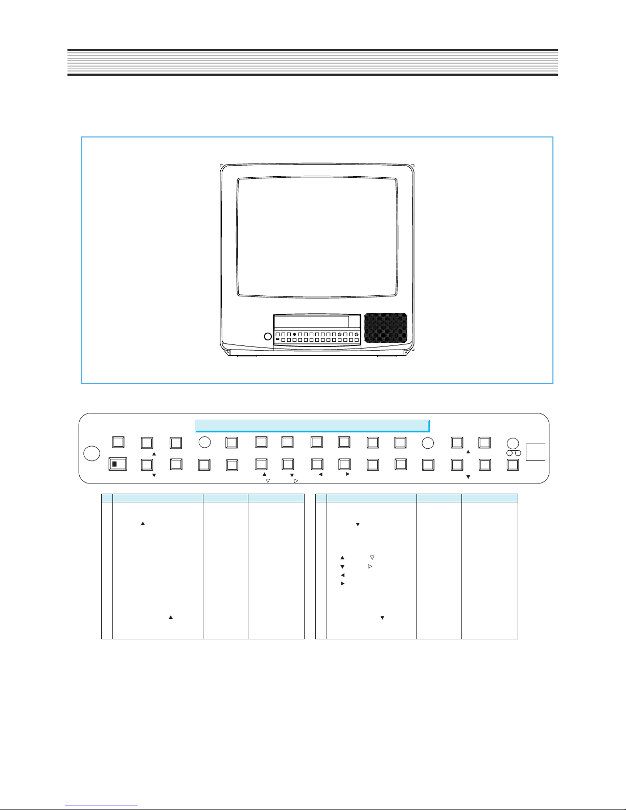
EXTERNAL VIEWS
1. FRONT VIEWS
No SW Name SW Type LED color No SW Name SW Type LED color
1 REMOTE SENSOR - - 17 SPEAKER - 2 STANDBY/ON SW+LED RED 18 SET LOCK Slide sw 3
VOLUME
SW only - 19
VOLUME
SW only 4 ALARM ON/OFF SW+LED RED 20 AUDIO SEL/MUTE (note2) SW+LED RED
5 MIC - - 21 AUTO SW+LED RED
6 CLEAR/DISPLAY (note1) SW only - 22 QUAD/P.B THROUGH SW+LED RED
7 ZOOM SW+LED RED 23
C1 / / SHIFT
SW+LED RED
8 FREEZE SW+LED RED 24
C2 / ))
SW+LED RED
9 PIP/TRK- SW+LED RED 25
C3 / / SET -
SW+LED RED
10 MENU/TRK+ SW only - 26
C4 /
SW+LED RED
11 STOP/EJECT SW only - 27 REW SW+LED RED
12 PAUSE/STILL SW+LED RED 28 PLAY SW+LED RED
13 LED(REPEAT REC) LED RED 29 FF SW+LED RED
14
REC/PLAY SPEED
SW only - 30
REC/PLAY SPEED
SW only 15 REC/REC CHECK SW+LED RED 31 TIMER SW+LED RED
16 LED(CST IN) LED RED 32 TALK SW+LED RED
F/L Door
17
2
19 32
STANDBY/ON
SET LOCK
VOL
VOL
3 4
20
ALARM
AUDIO/
MUTE
6
7 8 9 10
1211 15
23
21
22
24 25 26
27
28
29 30 31
AUTO
QUAD/
P.B THROUGH
CLEAR/
DISPLAY
ZOOM
C1 /
SHIFT
FREEZE
C2 /
SHIFT
PIP/
TRK-
C3 / /
SET -
MENU/
TRK+
C4 / /
SET +
STOP
/EJECT
REW
PAUSE/
STILL
PLAY
FF SPEED
SPEED
R.REC
14
TIMER
REC/
REC CHECK
MIC
TALK
OFF
ON
1
18
5
/ SHIFT
13
-Note 1 : Input th Ò CLEAR/DISPLAY KEYÓ over 3sec. It mode ÒDISPLAY MODEÓ.
-Note 2 : ÒAUDIO SEL/MUTE KEYÓ over 3sec. It mode Ò MUTE MODEÓ.
9
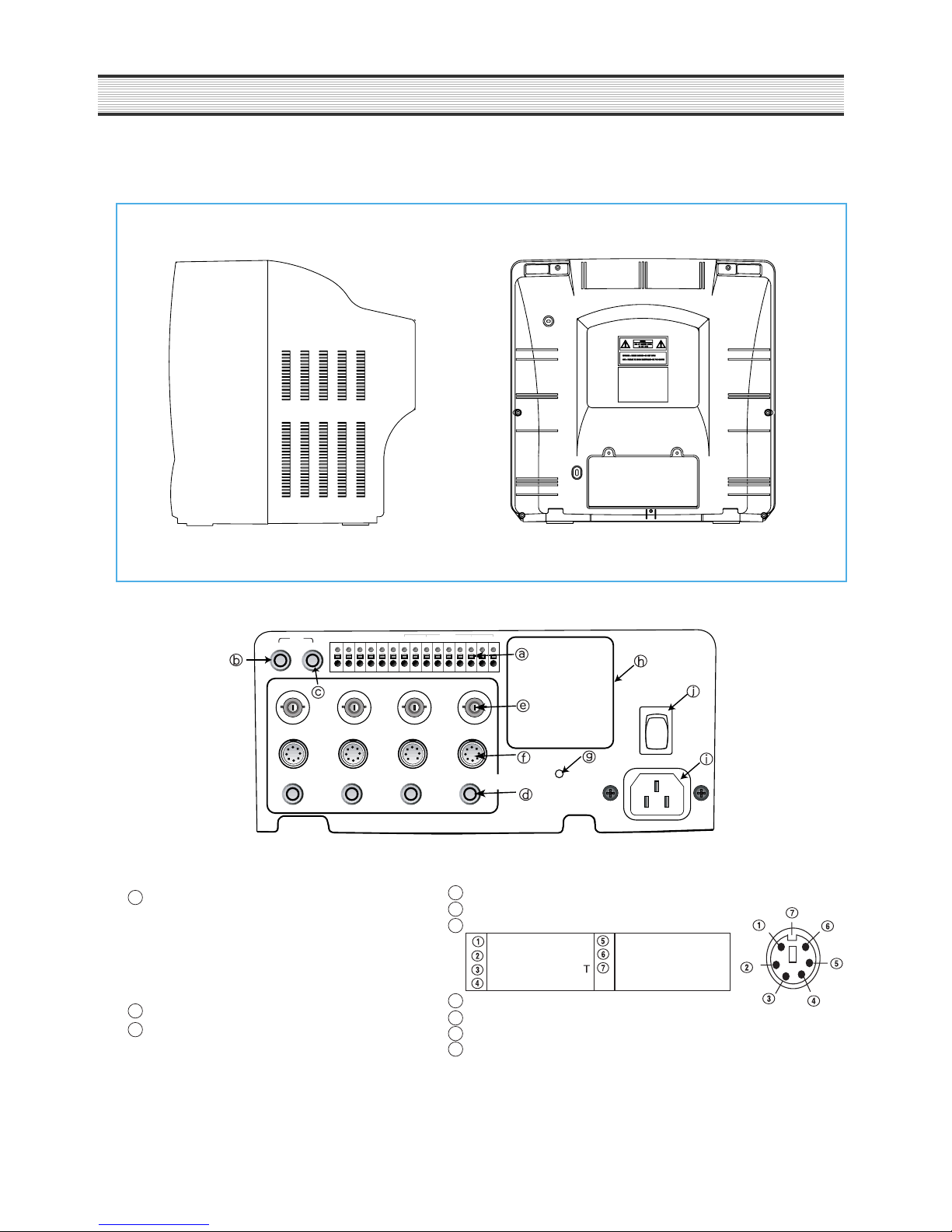
EXTERNAL VIEWS
2. BACK VIEWS
AUDIO MONITOR
VIDEO
DIN
AUDIO
INPUT RESET
ON
OFF
POWER
CH 1 CH 2 CH 3 CH 4
WARNING
OUT
TAPE
END
IN 1OUT
COMCOMCOMCOMCOMCOM
IN 2 IN 3 IN 4
ALARM
OUT
Terminal 1) N.C. 2) N.C.
AUDIO IN (CH1~CH4, rca type)
3) WARNING OUT 4) COM
VIDEO IN(CH1~CH4, bnc type)
5) TAPE END 6) COM
6 PIN MINI DIN(FOR SVC SPEC)
7) ALARM OUT 8) COM
DC 12V OUTPUT AUDIO OUTPUT
9) ALARM1 IN 10) COM AUDIO INPUT VIDEO INPUT
11) ALARM2 IN 12) COM TALK 12V OUTPU GND
13) ALARM3 IN 14) COM N.C
15) ALARM4 IN
RESET SW
AUDIO OUT (rca type)
MAIN POWER SW
MONITOR(VIDEO) OUT (rca type) AC POWER INPUT CORD
RS232C(optional/without SVC Model)
a
d
e
f
g
h
i
j
b
c
10
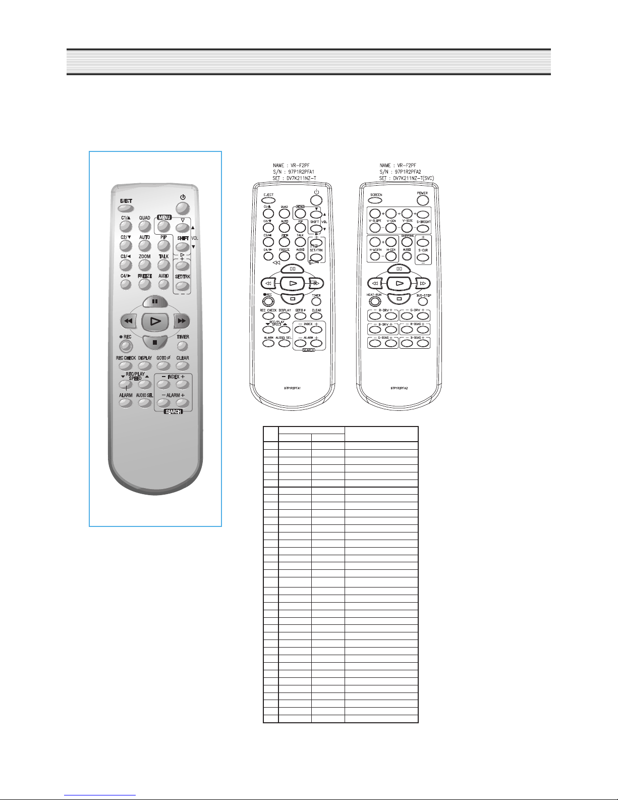
3. REMOCON
e.20"/14" T/L REMOCON KEY
USER REMOCON SVC MODE BY USER REMOCON
NO KEY CODE KEY NAME
CUSTOM DATA
* SVC MODE
1 15H 00 VOL UP/SHIFT ¡
1.POWER ON(EJECT)
2 15H 01 VOL DN/SHIFT ¢„
2.Make full screen
3 15H 02 REC/PLAY SPEED ¡ª
in CAM4.
4 15H 03 REC/PLAY SPEED ¡
3.Push "INDEX -, +,
5 15H 04 SET +
ALARM -, +" buttons
6 15H 05 SET -
in sequence within
7 15H 06 C1
10 seconds.
8 15H 07 C2
4.Press the POWER OFF key
9 15H 08 TIMER
to release SVC MODE.
10 1 5H 09 C3
11 15H 0D STOP
12 15H 0E PLAY
13 15H 0F FF
14 15H 10 REW
15 15H 11 PAUSE/STILL
16 1 5H 12 REC
17 15H 13 AUTO
18 15H 15 POWER
19 1 5H 16 PI P
20 15H 17 AUDIO SEL
21 15H 18 ALARM
22 15 H 19 TALK
23 15H 1A AUDIO ON
24 15H 1B REC CHECK
25 15H 1D DISPLAY
26 15H 1E QUAD
27 15H 1F GOTO 0
28 15H 21 EJECT
29 1 5H 22 MENU
30 15H 27 C4
31 15H 29 ZOOM
32 15H 31 ALARM 33 15H 33 INDEX +
34 15H 35 ALARM +
35 15H 36 CLEAR
36 15H 39 FREEZE
37 15H 3F INDEX -
EXTERNAL VIEWS
11
ALIGMENT INSTRUCTIONS
1. VCR DECK ADJUSTMENTS
1) X-DISTANCE & P2,P3 ADJUSTMENT(S10)
¥ Connect Path JIG to connector PS 04, Playback the test tape(DN-2,7KHz)
¥ Connect oscilloscope CH1 to V.SW(PS04#2), CH2 to PB RF(PS04 #1) and trigger on CH1.
¥ Enter the service mode and select service adjustment S10
¥ Use the VOL up button to set ATK Off CEN.
¥ Turn the X-distance screw to maximum of PB-RF.
¥ Use the VOL up button to set ATK Off MIN and MAX.
¥ If PB-RF is not smooth, adjust P2, P3.
✰ P2, P3
VH SW
RF
2) P.G ADJUSTMENT(S11)
¥ Playback the test tape(DN-2, 7KHz)
¥ Enter the service mode and select service adjustment S11
¥ Push the Ò RECÓ KEY once, P.G Adjustement is Automatically.
¥ Connect oscilloscope CH1 to V/SW(PS04#2), CH2 to CVS(PS04 #50 and trigger on CH1, Confirm The P.G is 6.5H(412msec).
3) AUDIO AZIMUTH ADJUSTMENT
¥ Playback the test tape(DN-2, 7KHz)
¥ Connect oscilloscope and level meter to Aout(PS04 #4).
¥ Turn the azimuth screw to maximum 7KHz level.
4) FACTORY OUTGOING MODE(S12)
¥ If you select the S12, then the set becomes factory outgoing status.
¥ You can see the channel to Ò O2Ó or if the set playback you can see the OSD ÒAUTO TRACKINGÓ.
12
ELECTRICAL ADJUSTMENT
Electrical adjustments: Alignment and electrical adjustment
- For these adjustments, use the equipment mentioned below and proceed by using the alignment tape and video
signal.
¥ Instrument and tools required
1. Color TV .
2. Oscilloscope having 10MHz or more bandwidth.
3. Color-bar generator.
¥ Signal level and input and output impedance requirement
1. video intput : Negative sync 1Vp-p standard composite video signal, 75?.
2. Video output : Same as above.
3. Audio input : Line ?8.8dBm 47K? Min.
4. Audio output : -6dBm 10K? Max.
¥ Adjustment sequence
The VCR should be adjusted in the sequence shown below.
horizontal sync
burst
0.714V
0.286V
0.286V
1Vpp
COLOR BAR SIGNAL WAVEFORM
COMBO
VCR DECK PATH VCR SERVO MONITOR
Adjustment
Adjustment
Adjustment
Adjustment
75
%
W
h
i
t
e
Y
e
l
l
o
w
C
y
a
n
Q
100
%
White
I
Black
G
r
e
e
n
M
a
g
e
n
t
a
R
e
d
B
l
u
e

13
ELECTRICAL ADJUSTMENT
1. SERVO/SYSCON CIRCUIT ADJUSTMENT METHOD
(1) VIDEO HEAD SWITCHING POSITION
Adjustment Part Checking Point Measuring Equipment Mode Test Tape
R595 TJ396P502 3PIN Oscilloscope Play DN-1(Color Bar)
¥ Connection Method
¥ Adjustment Procedure
1) Play back the test tape.
2) Set the oscilloscope in the chop mode connect the CH1 to SW pulse(P502 3PIN), the CH2 to TJ396(video out) with
CH1 triggering.
3) Adjust R595 for the positive trigger until 6.5?0.5H cycle before the vertical SYNC pulse.
R595
P502
TJ396
CH-2
Oscilloscope
CH-1
CH2
CH1
Trigger Position
6.5H 0.5H
1H
0.5H
Vertical SYNC
Signal
SW PULSE
(PT502 3PIN)
VIDEO OUT
(TJ396)
–

14
2 . MONITOR ADJUSTMENT
* HOW TO ENTER THE SVC MODE
1) POWER ON(EJECT MODE) and make full screen in CAM4.
2) Push INDEX-,+,ALARM-,+ buttons in sequence within 10 seconds.
Then, the screen will display FACTORY V0.1 text on the upper of the reft.
2-1 The adjustment of screen
1) Press the VOL UP, DOWN(S-BRIGHT +,-) key on the remote control to set the sub-bright.
( Setting data Ñ Philips CRT : 30 , Thomson CRT : ? , SAMSUNG CRT : ? )
In case of mass production in the factory, keeping the setting data value to EEPROM MASTER IC for setting of
sub-bright
2)Press the EJECT(SCREEN) key on the remote control so that make the horizontal line.
3)Adjust the screen volume of the FBT so that the horizontal line may be minimum light.
4)Press the EJECT(SCREEN) key on the remote control to release SCREEN mode.
2-2 The adjustment of focus
1) Apply NTSC RETMA pattern.
2) Call up the SVC Mode and make full screen in C4.
3) Adjust with the focus volume on the FBT until you get the most clear resolution line on the screen.
2-3 The adjustment of white balance
1) Call up the SVC Mode.
2) Adjust with ALARM,AUDIO SEL, ALARM-,+(G BIAS +/-,B BIAS +/-) keys so that only G,B bars in the high beam on
the instrument
3) Adjust with GOTO,CLEAR,REC/PLAY UP,DOWN (G DVR +/-,B DVR +/-) keys so that only G,B bars in the low beam
on the instrument may be located in the center.
4) The reference coordinates are X=288,Y=301
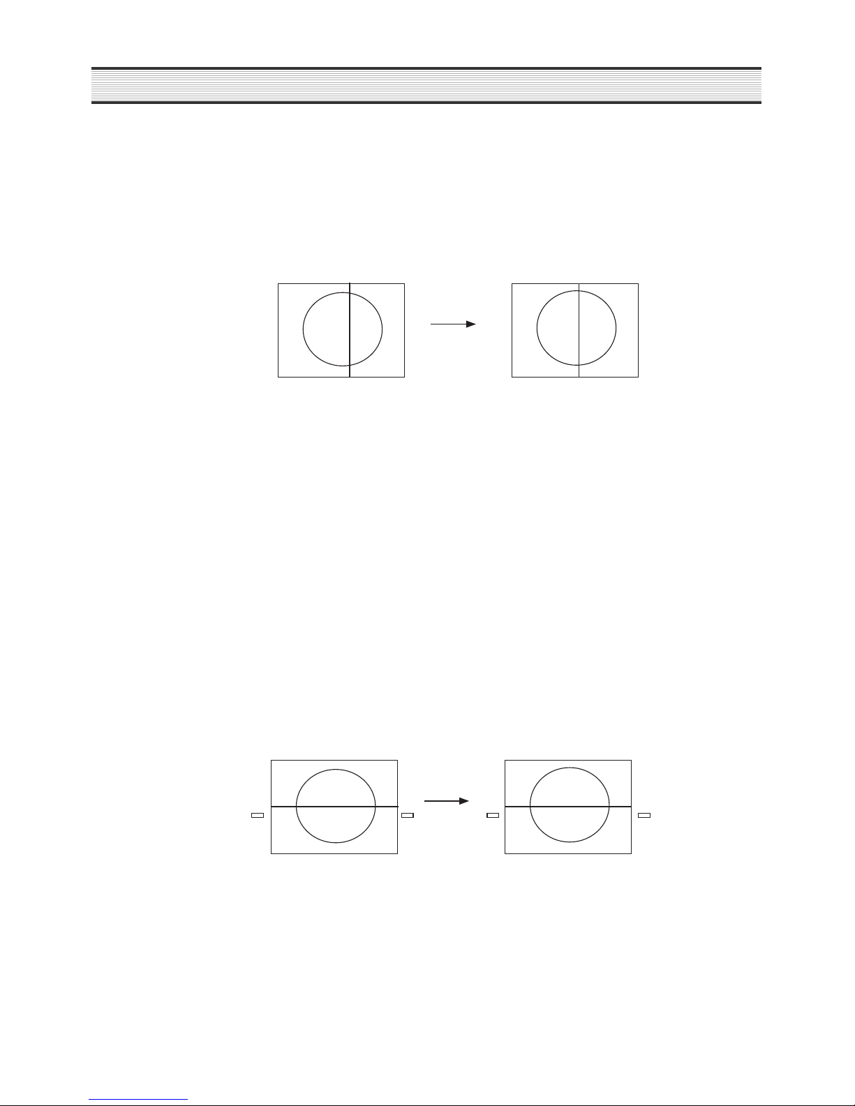
2-4 The adjustment of geometry
2-4-1 The adjustment of vertical center
1) Apply NTSC RETMA pattern.
2) Call up the SVC Mode and make full screen in C4.
3) Press QUAD, AUTO(V-CEN+ or V-CEN-) key and VERT CENT OSD will be displayed.
4) Adjust with QUAD,AUTO(V-CEN+/V-CEN-) keys so that the center mark of the CRT may be located on the
horizontal line in the middle of the pattern. In case of no center mark, adjust with QUAD, AUTO(V-CEN+/V-CEN-)
keys to obtain a vertically symmetrical pattern.
2-4-2 The adjustment of vertical size
1) Apply NTSC RETMA pattern.
2) Call up the SVC Mode and make full screen in C4
3) Press MENU,PIP(V-SIZE+ or V-SIZE-) key and VERT SIZE OSD will be displayed.
4) Adjust with MENU,PIP(V-SIZE+/V-SIZE-) keys so that the upper and the lower Ô+Õ marks of the RETMA pattern
may be located at the boundaries of the screen.
ELECTRICAL ADJUSTMENT
15
ELECTRICAL ADJUSTMENT
2-4-2 The adjustment of vertical size
1) Apply NTSC RETMA pattern.
2) Call up the SVC Mode and make full screen in C4
3) Press MENU,PIP(V-SIZE+ or V-SIZE-) key and VERT SIZE OSD will be displayed.
4) Adjust with MENU,PIP(V-SIZE+/V-SIZE-) keys so that the upper and the lower Ô+Õ marks of the RETMA
pattern may be located at the boundaries of the screen.
2-4-3 The adjustment of vertical slope
1) Apply NTSC RETMA pattern.
2) Call up the SVC Mode and make full screen in C4.
3) Press C1,C2(V-SLOPE+ or V-SLOPE-) key and V. LINEAR OSD will be displayed.
4) Referring to the upper side and lower side, adjust with C1,C2(V-SLOPE+/V-SLOPE-) keys so that RETMA
pattern may be symmetrical.
5) In case of mass production in the factory, keeping the default value is recommended for the adjustment of
V-SLOPE.
DEFAULT : -00003, Default value : -00003
2-4-4 The adjustment of horizontal center
1) Apply NTSC RETMA pattern.
2) Call up the SVC Mode and make full screen in C4.
3) Press ZOOM, FREEZ(H-CENTER+/H-CENTER-) key and HOR CEN OSD will be displayed.
4) Referring to the both side scales, adjust with ZOOM, FREEZ(H-CENTER+/H-CENTER-) keys so that
RETMA pattern may be symmetrical.
16
CIRCUIT OPERATION
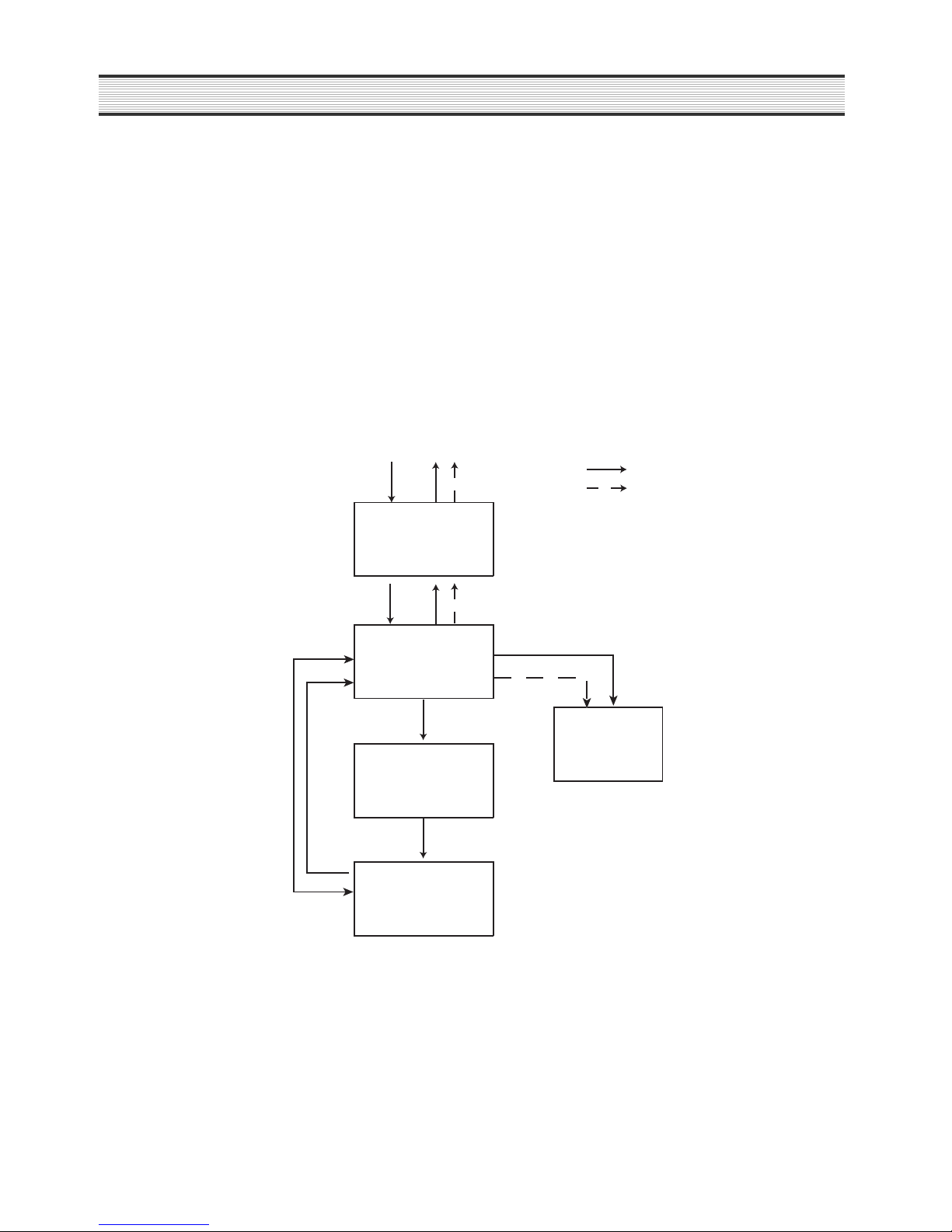
1. VIDEO PART
1-1) EE MODE
Video Signal which is output from monitor is input into pin 36 of IC301. It is amplified 6dB by AGC, then it is output
to pin 29 of IC301. The output signal is output to monitor through PJ301..
1-2) REC MODE
Video signal inputted from monitor will be recorded on the tape through head after FM modulated in IC.
1-3) PB MODE
FM signal pick uped through drum head from tape output to the pin 29 of IC301 as composite video signal after
60dB amplified and demodulation, then output to monitor through u-com OSD.
V-IN
V-OUT
REC
PB
AV SW JACK
Multiplexer
part
Servo Syscon
u-com OSD
MONITOR
PART
VIDEO
PART

17
CIRCUIT OPERATION
2. AUDIO PART
2-1) EE MODE
External AUDIO signal which is input to pin 78 of IC301 is output from pin 96 of IC301 after being ampli-fied
through ALC and Line Amp.
2-2) REC MODE
It will be the REC mode when REC 5V is input to base of Q206,Q202. Input signal will be replaced on the tape
through R/P HEAD after being amplified and modulated with Bias Frequency. Input signal is ampli-fied and
frequency compensated by REC AMP, ie. it means high band compensation in order to match AUDIO HEAD
characteristic. Each modeÕ s peaking frequency will be determined by BIAS element (R, L, C) of REC AMP. OSC
oscillation frequency is 70KHz sinewave, it will be used for tapeÕ s full erasing and AUDIO TRACK erasing.
2-3) PB MODE
The signal which is picked up from AUDIO HEAD is input to EQ AMP, then constant Audio Level will be output by
PB LEVEL fixed resistor after each mode is amplified and frequency is compensated.18H AUDIO output level will
be compensated with receiving Audio 24H(H) control of u-COM. Finally this out-put signal is output through AUDIO
conrol switching IC942, IC943.
18
CIRCUIT OPERATION
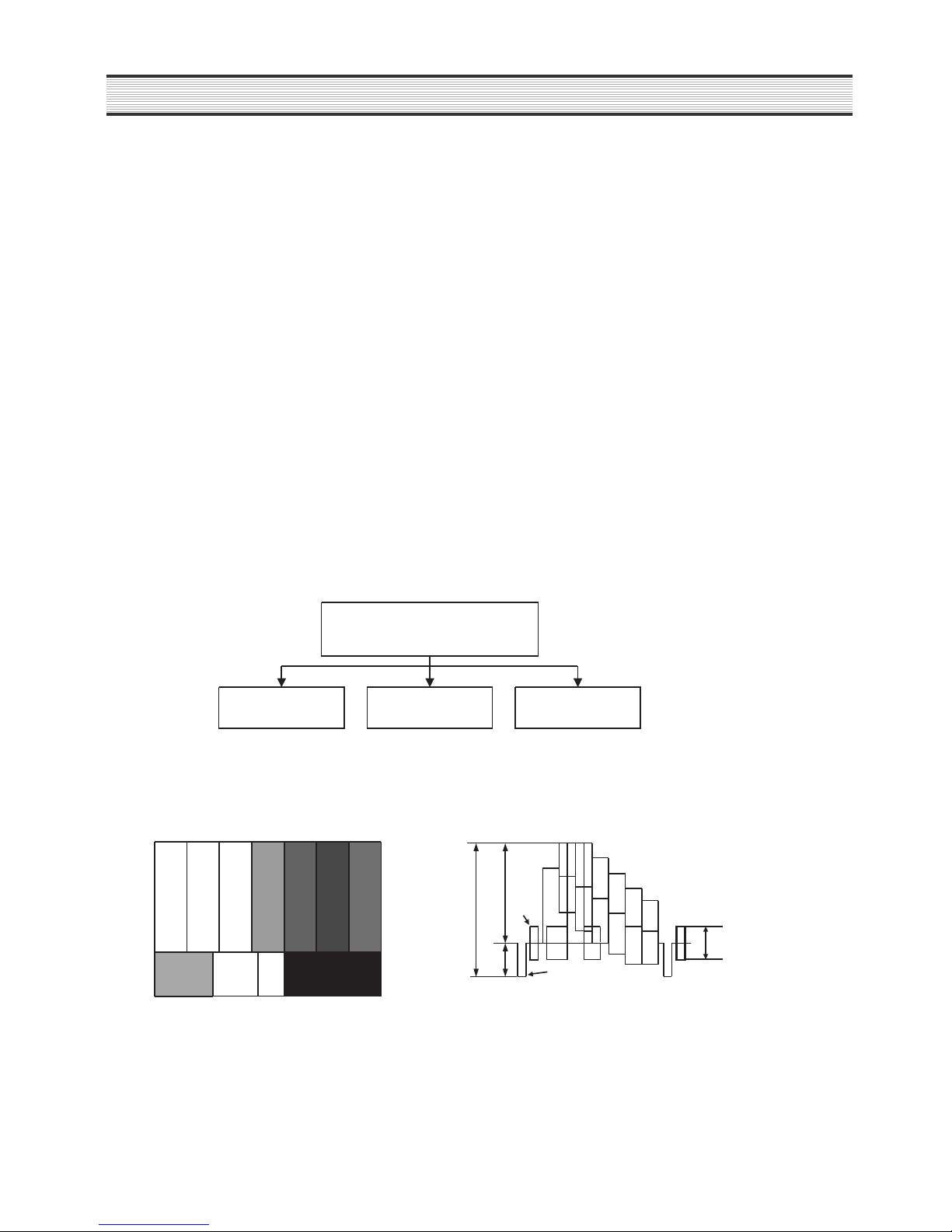
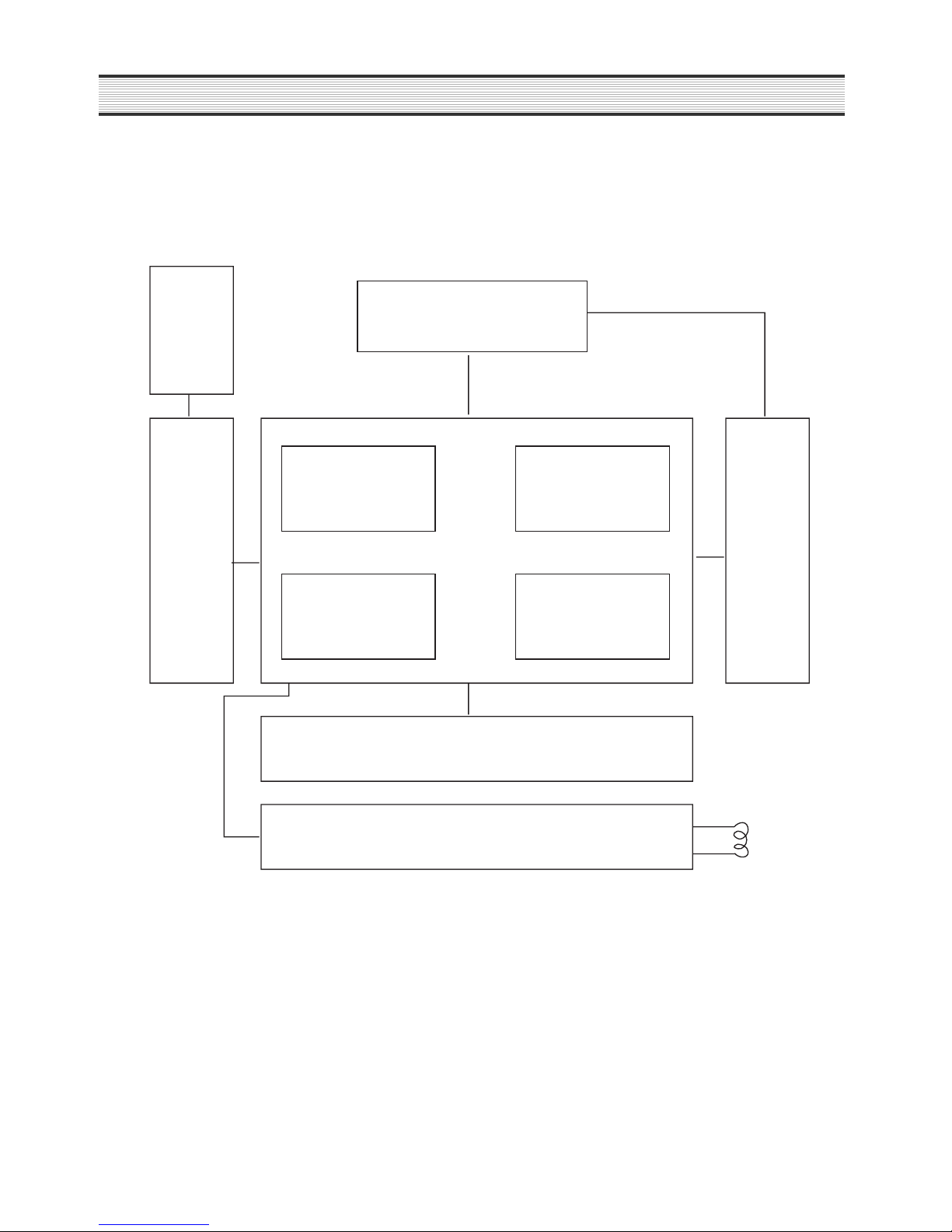
3. SYSTEM PART
3-1) System Block DIAGRAM
CRT &
DY COIL
Terminal Jack
PART
FBT
& High
Volt price
AV
PART
DECK K
MECH K-30
VCR Servo
Syscon . OSC
PART
Monitor
u-com IC
Multiplexer
Part
Front KEY Matrix
Power PART
Coil
Degauss

19
CIRCUIT OPERATION
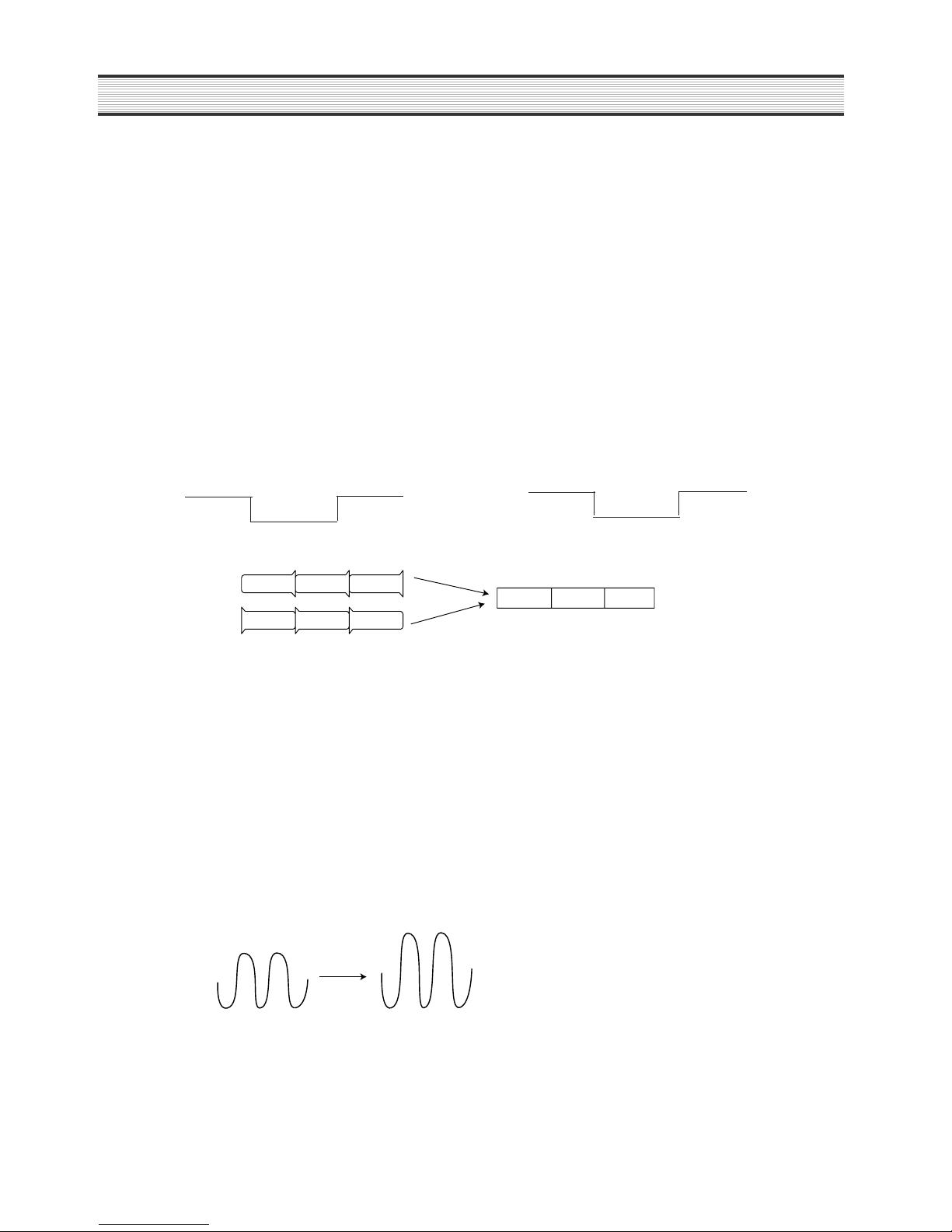
3-2) TIME LAPSE RECORDING METHOD
The numbers of VHS 2HOUR (SP), 6HOUR (EP) REC FIELD are 60 field/sec, then it will be 1FRAME = 33.3Ms,
1FIELD = 16.65Ms.
CAPSTAN MOTOR FG numbers for Time Lapse are 6HOUR(EP) = 720 numbers/sec, 2HOUR(SP) = 720*3=2160
numbers/sec.
¥ u-COM controls capstan motor (C I LIMIT) with capstan motor FG numbers. DRUM HEAD ON/OFF controlled by
HEAD AMP SW & REC mute signal.
¥ u-COM controls capstan motor (C I LIMIT) with capstan motor FG numbers. DRUM HEAD ON/OFF controlled by
HEAD AMP SW & REC mute signal.
LRLRLRLRLRLRL
16.65ms
18H(EP) RECORDING (20FIELD/SEC)
2H & 6H (60FIELD/SEC)
LRLRL
33.3ms
18H (20FIELD/SEC) : Recording 1 field per 3 fields
(Capstan FG numbers are ; 1SEC:720=33.3ms:X X=24)
(Capstan FG numbers are ; 1SEC:720=16.65ms:X X=12)
LRLRLRLRLRLRL
16.65ms
24H(SP) RECORDING (5FIELD/SEC)
: recording 1 field per 12 fields
LR
16.65ms*10=166.6ms
18H (20FIELD/SEC) : Recording 1 field per 3 fields
(Capstan FG numbers are ; 1SEC:2160=166.6ms:X X=36)
(Capstan FG numbers are ; 1SEC:720=16.65ms:X X=12)
20
CIRCUIT OPERATION
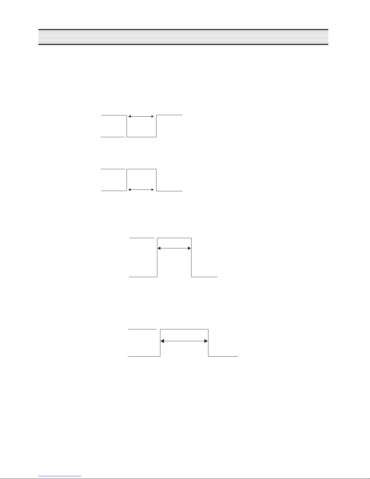
3-3) TERMINAL PART
ALARM INPUT 1,2,3,4
Connect DOOR SW&SENSOR etc and this port will be used for emergency recording by using open/ close status.
TAPE END OUT
When the recording tape ends during recording, end sensor will be detected. This port is used Alarm to outsider
until release the end sensor detecting.
WARNING OUTPUT
This port is used to inform emergency status of Time Lapse VCR Set to outsider.
5V
0V
500ms
500ms
N/O(NORMALY OPEN)
N/C(NORMALY CLOSED)
0V
5V
0V
END Detect
HIGH
5V
0V
EMERGENCY
status term
HIGH
5V
21
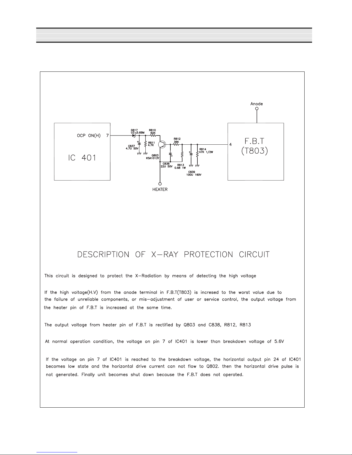
CIRCUIT OPERATION
X-RAY PROTECTION CIRCUIT(DQ-K2121N-P)
22
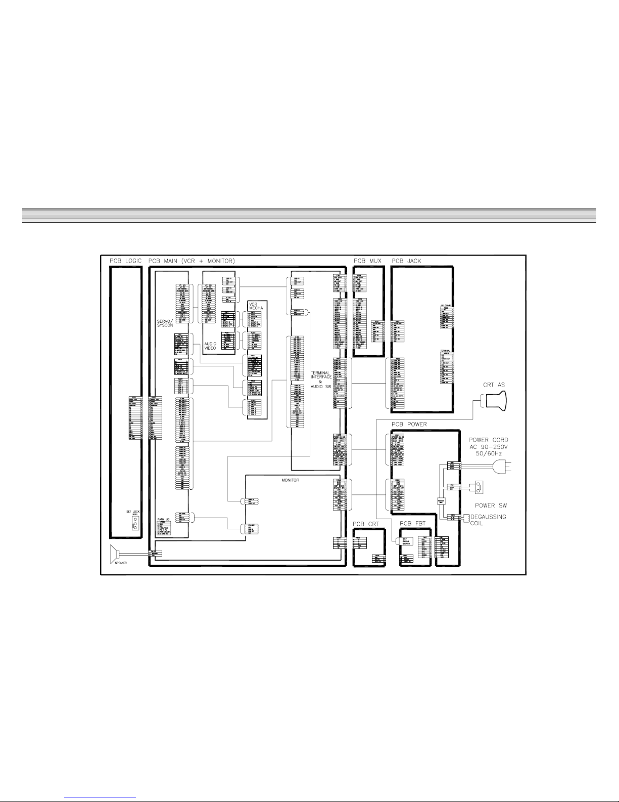
CIRCUIT INFORMATION
1. CONNECTION DIAGRAM(DQ-K2121N(D)-P)
23
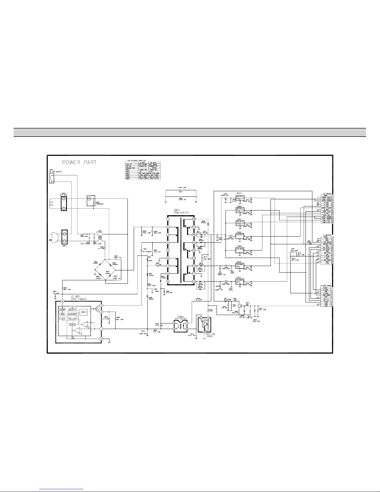
CIRCUIT INFORMATION
2. POWER SCHEMATIC DIAGRAM(DQ-K2121N(D)-P)
 Loading...