


Daewoo D35S-2, D40S-2, D45S-2, D45SC-2, D40SC-2 Disassembly/assembly
...
Disassembly &
Assembly
Lift Trucks Vehicle Systems
D35S-2, D40S-2, D45S-2
D40SC-2, D45SC-2, D50SC-2
G35S-2, G40S-2, G45S-2
G40SC-2, G45SC-2, G50SC-2
SB2204E00
Jun. 1999

Important Safety Information
Most accidents involving product operation, maintenance and repair are caused by failure to observe basic safety
rules or precautions. An accident can often be avoided by recognizing potentially hazardous situations before an
accident occurs. A person must be alert to potential hazards. This person should also have the necessary
training, skills and tools to perform these functions properly.
Read and understand all safety precautions and warnings before operating or performing lubrication,
maintenance and repair on this product.
Basic safety precautions are listed in the ÒSafetyÓ section of the Service or Technical Manual. Additional safety
precautions are listed in the ÒSafetyÓ section of the owner/operation/maintenance publication.
Specific safety warnings for all these publications are provided in the description of operations where hazards
exist. WARNING labels have also been put on the product to provide instructions and to identify specific hazards.
If these hazard warnings are not heeded, bodily injury or death could occur to you or other persons. Warnings in
this publication and on the product labels are identified by the following symbol.
Improper operation, lubrication, maintenance or repair of this product can be dangerous and could result
in injury or death.
Do not operate or perform any lubrication, maintenance or repair on this product, until you have read and
understood the operation, lubrication, maintenance and repair information.
Operations that may cause product damage are identified by NOTICE labels on the product and in this
publication.
DAEWOO cannot anticipate every possible circumstance that might involve a potential hazard. The warnings in
this publication and on the product are therefore not all inclusive. If a tool, procedure, work method or operating
technique not specifically recommended by DAEWOO is used, you must satisfy yourself that it is safe for you and
others. You should also ensure that the product will not be damaged or made unsafe by the operation, lubrication,
maintenance or repair procedures you choose.
The information, specifications, and illustrations in this publication are on the basis of information available at the
time it was written. The specifications, torques, pressures, measurements, adjustments, illustrations, and other
items can change at any time. These changes can affect the service given to the product. Obtain the complete
and most current information before starting any job. DAEWOO dealers have the most current information
available.
WARNING
1


Vehicle Systems Index
Index
Brake Hydraulic Booster..........................................21
Counterweight..........................................................36
Engine......................................................................39
Hood Assembly..........................................................5
Hydraulic Control Valve ...........................................27
Hydraulic Oil Filter Assembly...................................37
Hydraulic Pump .......................................................33
Overhead Guard ........................................................6
Primary Lift Cylinder ................................................12
Secondary Lift Cylinders............................................9
Steer Axle ................................................................23
Steering Cylinder .....................................................24
Steering Knuckles, Kingpins And Bearings .............22
Steering Unit ............................................................15
Steering Wheel ........................................................15
Tie Rods...................................................................21
Tilt Cylinders ..............................................................7
Tires And Rims (Steer) ............................................26
Transaxle .................................................................37
3

Vehicle Systems Disassembly & Assembly5
Disassembly & Assembly
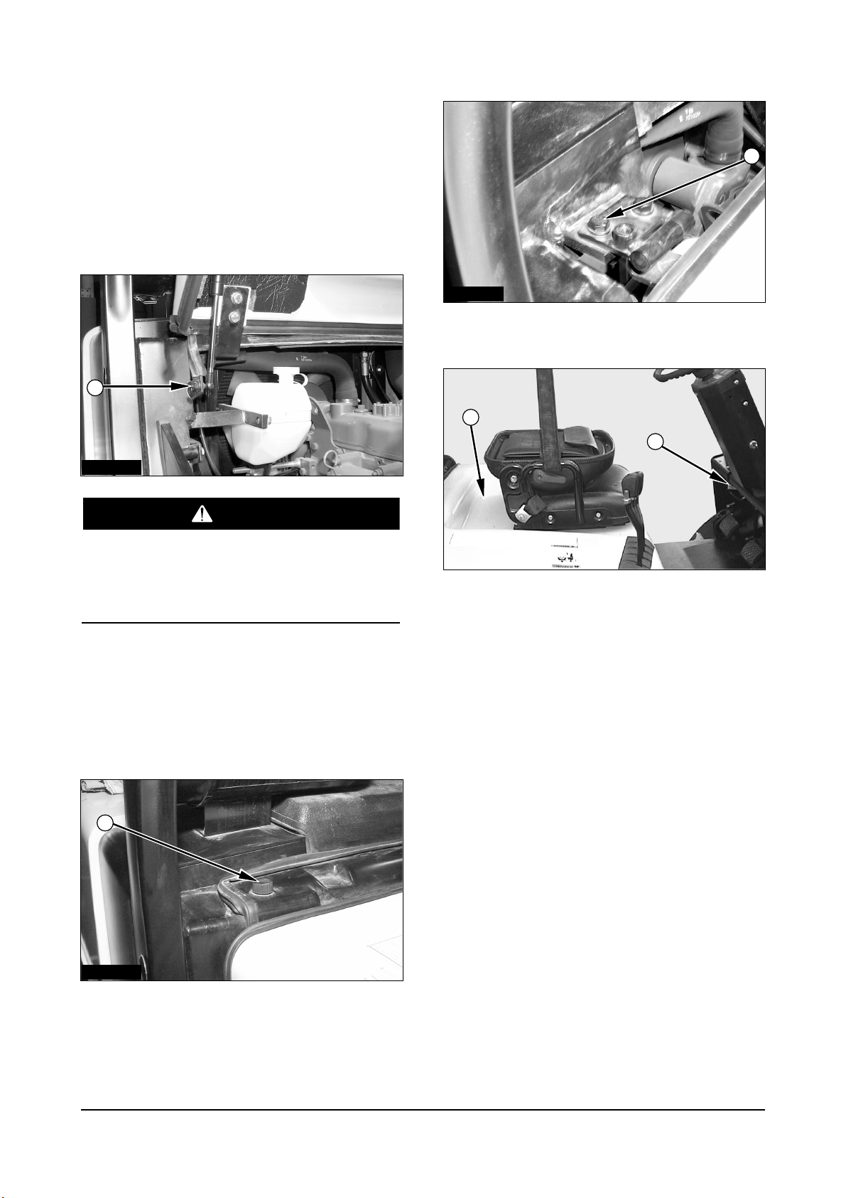
Hood (with seat) Assembly
Remove & Install Hood (with seat)
Assembly
The hood and seat assembly can fall when nut (1)
is removed from the support cylinder rod. To avoid
personal injury, support the seat and hood
assembly before removing nut (1).
1. Raise the hood. Support the hood with a hoist.
2. Remove nut (1) from the support cylinder. Remove
the cylinder rod from the bracket.
3. Lower the hood.
4. Remove the bolts (2) from the cover. Remove
cover.
5. Remove the washers and four bolts (3).
6. Release latch (5). Use the hoist to remove hood
and seat assembly (4). The hood and seat
assembly weighs 52 kg (115 lb).
7. Install the hood and seat assembly in the reverse
order of removal.
IACD201P
IACD202P
IDCD054P
IACD203P
1
3
5
4
2
WARNING
Vehicle Systems Disassembly & Assembly
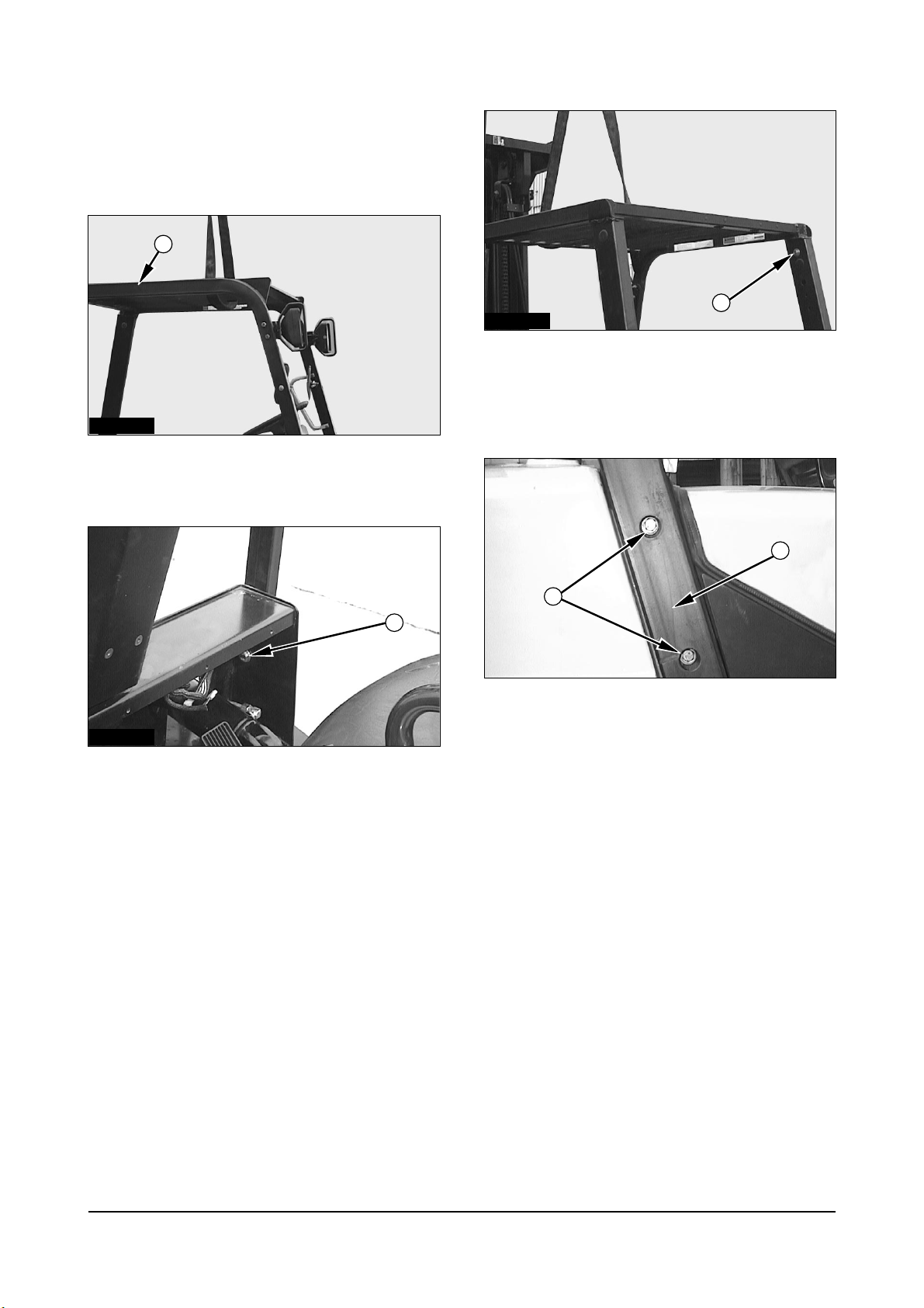
Overhead Guard
Remove & Install Overhead Guard
1. Support overhead guard (1) with lifting straps and
a hoist.
2. Remove the washers, nuts, and two bolts (2).
3. Remove the washers, nuts, and two bolts (3).
4. Remove front overhead guard (1), Front overhead
guard (1) weighs 30 kg (66 lb).
5. Remove the washers, nuts, and four bolts (4).
6. Remove rear Leg (5).
7. Install front overhead guard (1) and rear leg (5) in
the reverse order of removal.
6
IDCD055P
IDCD056P
IDCD057P
IDCD058P
1
3
4
5
2
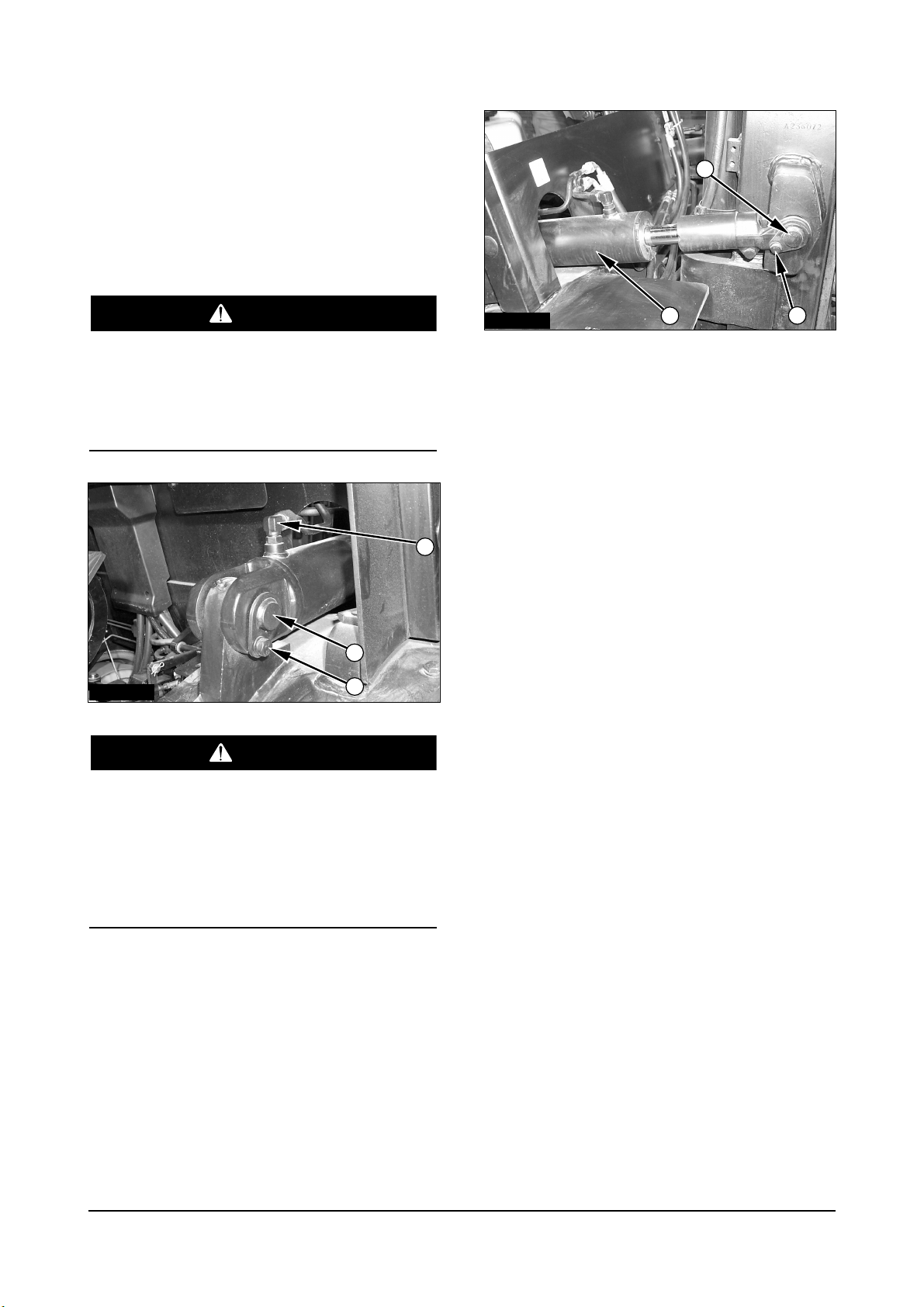
Vehicle Systems Disassembly & Assembly
Tilt Cylinders
Remove & Install Tilt Cylinders
NOTE : The procedure for removing and installing
the tilt cylinders is the same for both cylinders.
If both tilt cylinders are removed at the same time
the mast can fall. To avoid possible personal
injury, make sure the mast is securely held in
place or supported by a hoist before removing the
tilt cylinders.
To prevent personal injury, move the control
levers backward and forward to release any
pressure in hydraulic system. Slowly loosen the
cap of the hydraulic tank to release any pressure
in the tank. Be cautious of hot hydraulic oil when
any lines are disconnected in the hydraulic
system.
1. Disconnect elbow (2). Remove retainer bolt (3)
and pin (1).
2. Remove retainer bolt (6) from pin (5). Remove pin
(5).
3. Remove tilt cylinder (4).
4. Install the tilt cylinder in the reverse order of
removal.
7
IACD204P
IACD205P
2
6
5
4
3
1
WARNING
WARNING
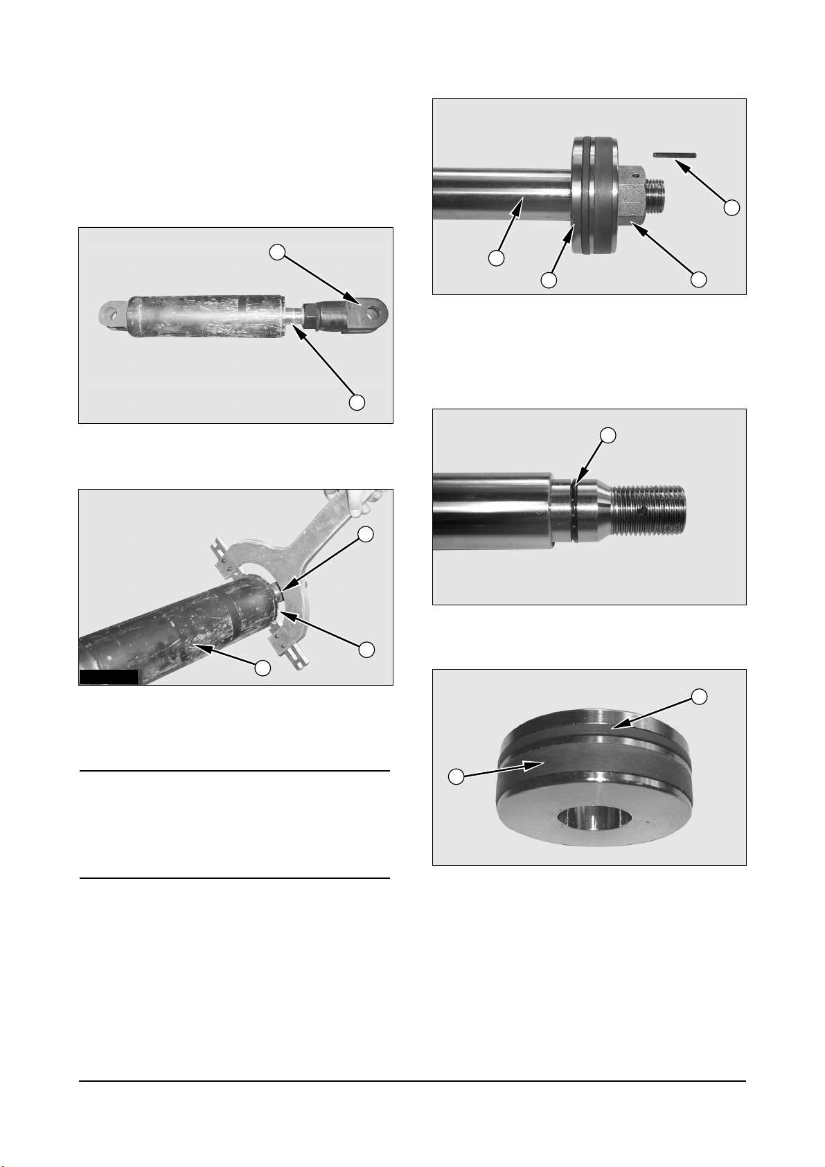
Vehicle Systems Disassembly & Assembly
Disassemble & Assemble Tilt
Cylinders
Start By:
a. Remove tilt cylinder.
1. Remove eye (1) from the rod assembly (4).
2. Remove rod cover (2) from the cylinder tube (3)
using a spanner wrench.
NOTICE
Use extra care not to damage the highly finished
surface of the cylinder rod and the bore of the clylinder
tube during disassembly and assembly of the tilt
cylinder.
3. Remove rod assembly (4) from the cylinder body.
4. Remove pin (5) inside hole and nut (6) from the
cylinder rod (4).
5. Remove piston (7) from the cylinder rod.
6. Remove O-ring seal (8) from the cylinder rod.
7. Remove wear ring (9) and slipper seal (10) from
the piston.
8
ICCD002P
ICCD003P
ICCD005P
ICCD006P
ICCD004P
1
4
4
8
10
9
2
3
4
7
6
5
Vehicle Systems Disassembly & Assembly
8. Remove O-ring seal (11) and backup ring (12)
from the rod cover (2).
9. Remove wiper seal (13), backup ring (14), U-
packing (15) and DU-bush (16) from the rod cover.
NOTE : Assemble the tilt cylinder in the reverse
order of disassembly.
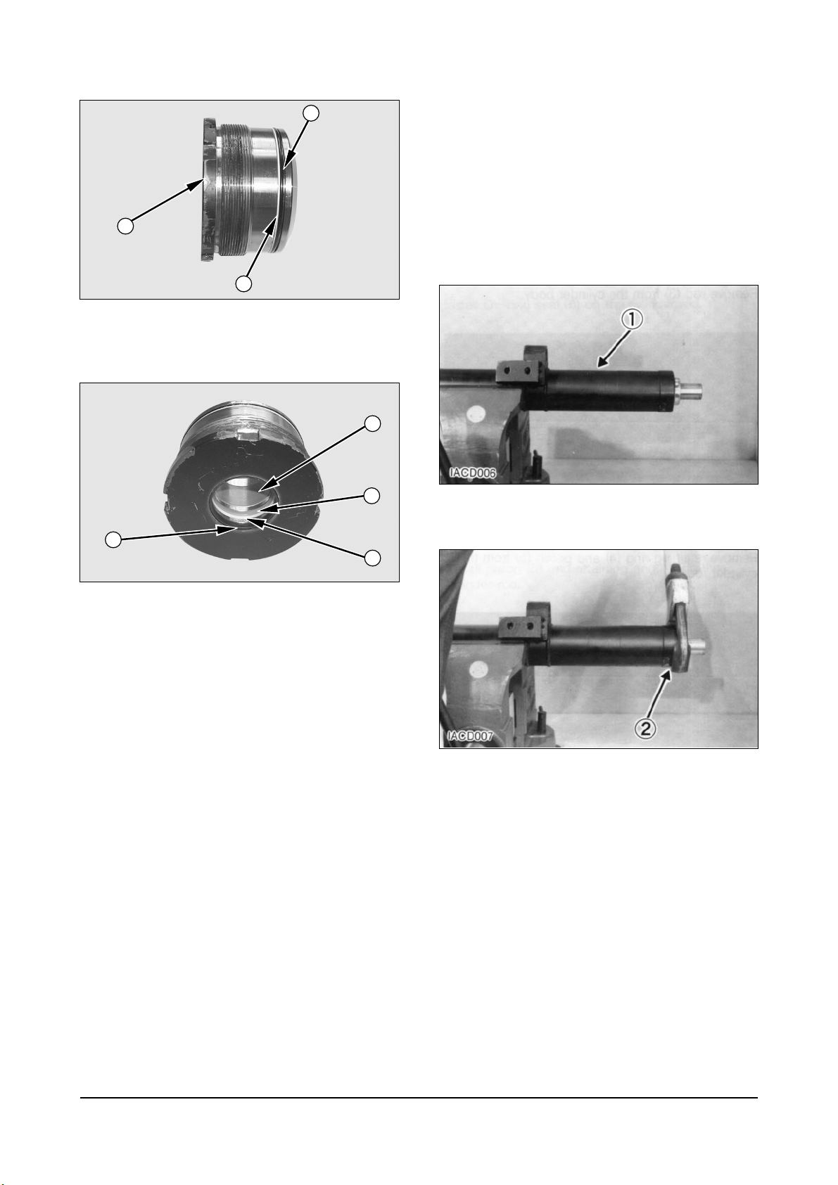
Secondary Lift Cylinders
Disassemble Secondary Lift
Cylinders
Start By :
a. Remove secondary lift cylinders.
1. Put secondary lift cylinder (1) in position as shown.
2. Remove head assembly (2) with tool.
9
ICCD007P
ICCD008P
11
2
12
13
16
15
14
Vehicle Systems Disassembly & Assembly
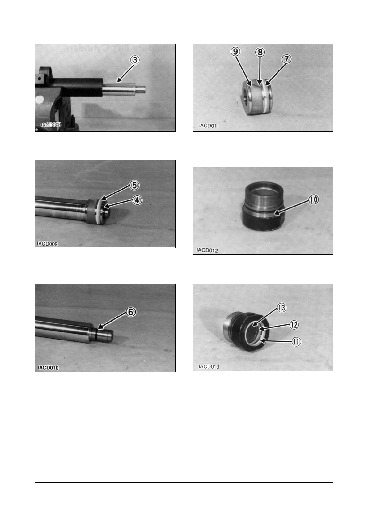
3. Remove rod (3) from the cylinder body.
4. Remove retaining ring (4) and piston (5) from the
cylinder rod.
5. Remove O-ring seal (6) from the cylinder rod.
6. Remove O-ring seal (7), back-up ring (8) and seal
(9) from the piston.
7. Remove O-ring seal (10) from the head assembly.
8. Remove wiper seal (11), seal (12) and bush (13)
from the head assembly.
10
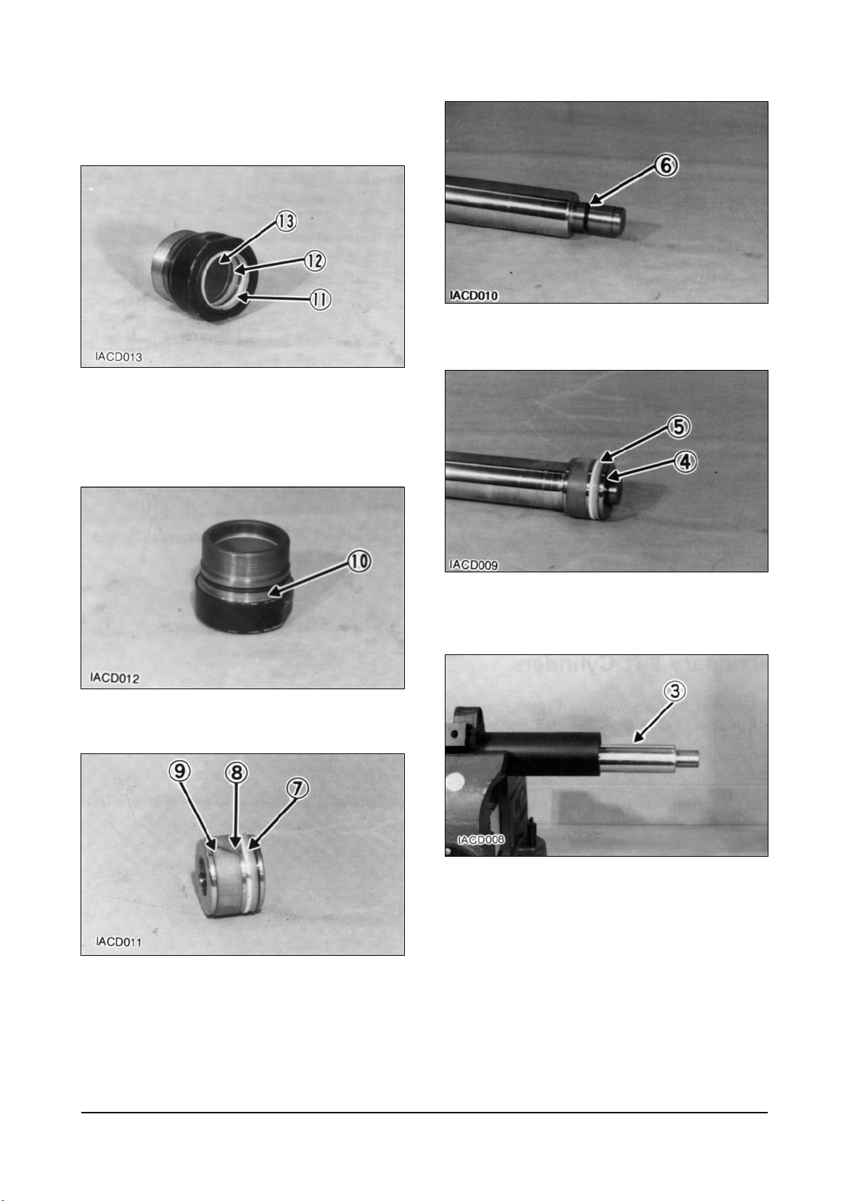
Vehicle Systems Disassembly & Assembly
Assemble Secondary Lift
Cylinders
1. Install bush (13) and seal (12).
2. Install wiper seal (11). Install the seal with the lip
toward the outside.
3. Install O-ring seal (10) onto the head assembly.
4. Install seal (9), back-up ring (8) and O-ring seal (7)
on the piston.
5. Install O-ring seal (6) on the cylinder rod.
6. Install piston (5) and retaining ring (4) on the
cylinder rod.
7. Install cylinder rod (3) in the cylinder body.
11
Vehicle Systems Disassembly & Assembly
8. Install head assembly (2) on the cylinder rod and
tighten using tool.
End By :
a. Install secondary lift cylinders.
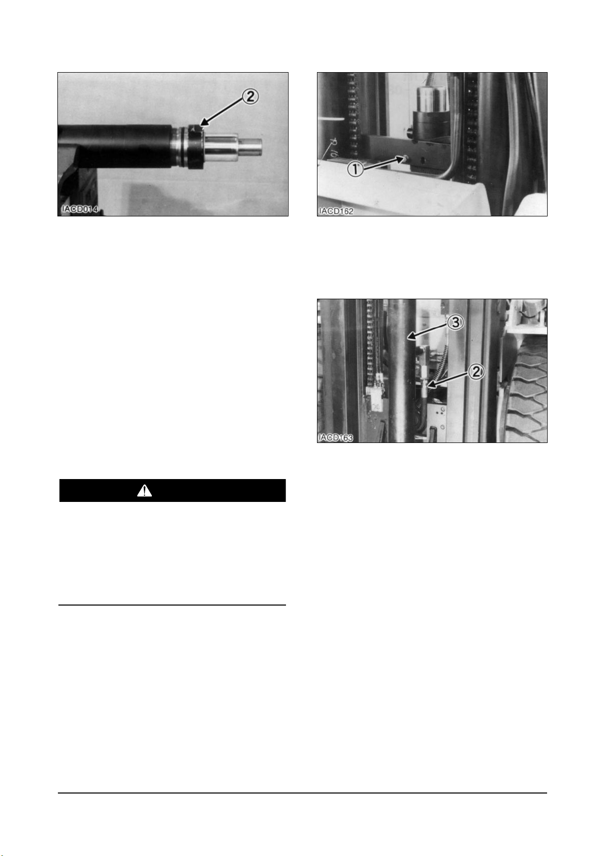
Primary Lift Cylinder
Remove & Install Primary Lift
Cylinder
Start By :
a. Remove carriage.
To prevent personal injury, move the control
levers backward and forward to release any
pressure in hydraulic system. Slowly loosen the
cap of the hydraulic tank to release any pressure
in the tank. Be cautious of hot hydraulic oil when
any lines are disconnected in the hydraulic
system.
1. Fasten nylon straps and hoist to the primary lift
cylinder.
2. Remove bolt (1).
3. Pull the cylinder out far enough to disconnect
hydraulic hose (2). Remove primary lift cylinder
(3).
4. Install primary lift cylinder (3) in the reverse order
of removal.
End By :
a. Install carriage.
12
WARNING
 Loading...